1
User’
User’s
LG Programmable Logic Controller
GLOFA
G3F – RD3A
G4F – RD2A
LG Industrial Systems
CONTENTS Chapter 1.
1.1
1.2
INTRODUCTION
Features 1 – 1
Glossary 1 – 2
1.2.1
A – Analog Value 1 – 2
1.2.2
D – Digital Value 1 – 2
1.2.3
PT 1 – 2
1.2.4
Burn-out function 1 – 2
Chapter 2.
SPECIFICATIONS
2.1
General Specifications 2 – 1
2.2
Performance Specifications
2 – 2
2.3 Names of Parts and Functions 2 – 3
2.3.1 G3F-RD3A 2 – 3
2.3.2 G4F-RD2A 2 – 4
2.4
RTD Input Module Characteristics 2 – 5
2.4.1
Temperature Conversion Characteristics
2.4.2 Conversion Speed
2 – 5
2 – 5
2.4.3 Accuracy 2 – 5
2.4.4 Burn-out Function 2 – 6
2.5
Connection between a Pt and RTD Input Module 2 – 7
Chapter 3.
3.1
INSTALLATION AND WIRING
Installation 3 – 1
3.1.1 Installation Ambience 3 – 1
3.1.2 Handling Precautions 3 – 1
3.2
Wiring Precautions 3 – 2
Chapter 4.
TROUBLESHOOTING
4.1
Errors Indicated by RUN LED Flickering
4 – 1
4.2
Troubleshooting Procedure 4 – 2
4 – 2
4.2.1
RUN LED Flickering
4.2.2
RUN LED Off
4.2.3
Detected Temperature Value Unreadable from the CPU Module 4 – 3
4.2.4
Input Value of the RTD Is Not Consistent with
4 – 2
The Detected Temperature Value
4.2.5
Chapter 5.
4 – 4
RTD Input Module Hardware Defect 4 – 4
DIMENSIONS.
5.1
G3F-RD3A Dimensions 5 – 1
5.2
G4F-RD2A Dimensions 5 – 2
Chapter 6.
Standard Resistance Value of Pt/RTD 6 – 1
Chapter 7.
FUNCTION BLOCKS
7.1
Inserting Function Blocks for RTD Input Module in GMWIN 7 – 1
7.2
Local Function Blocks 7 – 2
7.2.1
Module Initialization (G3F-RD3A:RTD3INI, G4F-RD2A:RTD2INI) 7 – 2
7.2.2
Reading the Detected Temperature Value of the Module(Array Type)
(G3F-RD3A:RTD3ARD, G4F- RD2A:RTD2ARD) 7 – 3
7.2.3
Reading the Detected Temperature Value of the Module (Single Type)
(G3F-RD3A : RTD3RD, G4F-RD2A : RTD2RD) 7– 4
7.3
Remote Function Blocks 7 – 5
7.3.1
Module Initialization (G3F-RD3A:RTDR3INI, G4F-RD2A:RTDR2INI) 7 – 5
7.3.2
Reading the Detected Temperature Value of the Module 7 – 6
(G3F-RD3A:RTDR3ARD, G4F-RD2A:RTDR2ARD)
7.4
Errors on Function Block 7 – 7
7.4.1
Errors Indicated by the Output Variable STAT 7 – 7
7.4.2
Error Indicated by the Output Variable ALM_CODE in the Array Type
Detected Temperature Value Reading Function Block 7 – 7
Chapter 8.
PROGRAMMING
8.1
A Program for Output of the Detected Temperature Value as a BCD Value 8 – 1
8.2
A Program for Conversing the Detected Temperature Value(°°C) into Fahrenheit(°°F)
and Output as a BCD Value 8 – 6
8.3
A Program when Loading the RTD Input Module onto the Remote I/O Station 8 – 9
PRECAUTIONS
Be sure to read carefully the safety precautions given in data sheet and user’s manual before operating the module
and follow them.
The precautions explained here only apply to the G3F-RD3A and G4F-RD2A.
For safety precautions on the PLC system, see the GLOFA GM3/4 User’s Manuals.
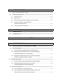
A precaution is given with a hazard alert triangular symbol to call your attention, and precautions are represented
as follows according to the degree of hazard.
!
WARNING
If not provided with proper prevention, it can cause death or fatal
injury or considerable loss of property.
!
CAUTION
If not properly observed, it can cause a hazard situation to result
in severe or slight injury or a loss of property.
However, a precaution followed with
!
CAUTION
can also result in serious conditions.
Both of two symbols indicate that an important content is mentioned, therefore, be sure to observe it.
Keep this manual handy for your quick reference in necessary.
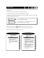
Design Precautions
!
CAUTION
Do not run I/O signal lines and
compensation wires near to high
voltage line or power line.
Separate them as 100 mm or
more as possible. Otherwise,
noise can cause module malfunction.
Installation Precautions
!
CAUTION
Operate the PLC in the environment conditions given in the
general specifications.
If operated in other environment
not specified in the general
specifications, it can cause an
electric shock, a fire, malfunction
or damage or degradation of the
module
Make sure the module fixing projections is inserted into the module fixing hole and fixed.
Improper installation of the module can cause malfunction, disorder or falling.
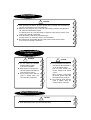
Wiring Precautions
!
CAUTION
When grounding a FG terminal, be sure to provide class 3 grounding which is dedicated to
the PLC. If not grounded, It can cause malfunction.
Before the PLC wiring, be sure to check the rated voltage and terminal arrangement for
the module and observe them correctly.
If a different power, not of the rated voltage, is applied or wrong wiring is provided, it can
cause a fire or disorder of the module.
Drive the terminal screws firmly to the defined torque.
If loosely driven, it can cause short circuit, a fire or malfunction.
Be careful that any foreign matter like wire scraps should not enter into the module.
It can cause a fire, disorder or malfunction.
Test Run and Maintenance
Precautions
!
!
WARNING
Do not contact the terminals
while the power is applied.
It can cause malfunction.
When cleaning or driving a terminal screw, perform them after the
power has been turned off
Do not perform works while the
power is applied, which can
cause disorder or malfunction.
CAUTION
Do not separate the module from
the printed circuit board(PCB), or
do not remodel the module.
They can cause disorder, malfunction, damage of the module
or a fire.
When mounting or dismounting
the module, perform them after
the power has been turned off.
Do not perform works while the
power is applied, which can
cause disorder or malfunction.
Waste Disposal Precautions
!
CAUTION
When disposing the module, do it as an industrial waste.
Chapter 1.
INTRODUCTION
Chapter 1.
INTRODUCTION
These two units are called G3F-RD3A and G4F-RD2A. The G3F-RD3A is an Pt input module used with the
CPU of GLOFA PLC GM1/2/3 series, and the G4F-RD2A is used with the CPU of GM4 series. Hereafter, the
two units are called the RTD input module
The RTD input module is a module that converts the temperature data(°C) input by the Pt (Pt100 or JPt100)
into a signed 16 bit digital binary data and outputs it.
1.1 Features
1) With direct connection of the RTD input module, the temperature data(°C) can be converted into a digital
value to be processed in the PLC.
2) The temperature data(°C) input can be processed to one digit after the point as a digital value.
3) One module can be connected to G3F-RD3A 8-point or G4F-RD2A 4-point Pt100 or JPt100.
4) The RTD input module has Pt100, Jpt100 or cable burn-out function at their every channel.
5) The RTD input module detects the out-of-range temperature that is input by Pt100 or JPt100.
6) The 5 digit LED display included in the G3F-RD3A displays the temperature input value and error code.
1-1
Chapter 1.
INTRODUCTION
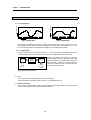
1.2 Glossary
Temperature
Number of man
1.2.1 A - Analog Value
time
time
[Fig 1.2] Digital Value
[Fig 1.1] Analog Value
The continuous changeable value such as voltage, current, temperature, velocity, pressure and flow is
called analog value. For example, temperature changes continuously with time as shown in Fig. 1.1. The
PLC can process that continuous changeable temperature by use of the RTD input module.
1.2.2 D - Digital Value
In Fig.1.2, the number of man can be counted as 0, 1, 2, 3. The non-continuous changeable value as such
is called a digital value. On and Off signals can be denoted as a digital value 0 and 1, respectively.
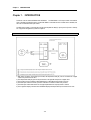
A/D
Conversion
CPU
(Digital
processing
Analog
-200~-600
Analog value cannot be directly input to the CPU
module for digital processing. Therefore, analog value
should be converted into a digital value to be input to
the CPU module. In addition, for external output of
analog value, digital value of the CPU module should
be converted into analog value.
D/A
Conversion
Analog
0~±10V or
4~20mA
[Fig 1.3] Processing in the PLC
1.2.3 Pt
This is a sensor that detects temperature as the type of resistance.
The Pt 100 outputs the resistance value of 100.00 Ω for the temperature of 0 °C
1.2.4 Burn-out Function
If a part of the connected RTD or cable is disconnected, the out-of-range voltage is input by the internal
burn-out circuit and the connection or disconnection is detected.
1-2
Chapter 2.
SPECIFICATIONS
Chapter 2.
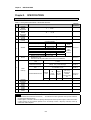
2.1
SPECIFICATIONS
General Specifications
Table 2.1 shows general specifications of the GLOFA GM series.
No
Item
1
Operating
ambient
temperature
Storage
ambient
temperature
Operating
humidity
Storage
humidity
2
3
4
0 ~ 55 °C
-25 ~ +75 °C
5 ~ 95%RH, non-condensing.
5 ~ 95%RH, non-condensing.
Frequency
5
6
Vibration
Shocks
7
Noise
Immunity
9
10
11
Operating
Atmosphere
Operation
Altitude
Pollution
degree
Cooling
method
Occasional vibration
Acceleration
Amplitude
Sweep
Count
0.075 mm
10 times in
9.8 m/s 2{1 G}
each
Continuous vibration
direction
Frequency
Acceleration
Amplitude
for X,Y,Z
0.035 mm
10≤f <57 Hz
2
4.9 m/s {0.5G}
57≤f≤150 Hz
! Maximum shock acceleration: 147 m/s2{15G}
! Duration time : 11ms
! Pulse wave: half sine pulse (3 times in each of X, Y and Z directions)
Square wave impulse
± 1,500 V
noise
10≤ f<57 Hz
57≤f≤150 Hz
Electrostatic discharge
Voltage : 4 kV (contact discharge)
Radiated electromagnetic
field
27 ~ 500 MHz, 10 V/m
Fast transient/burst noise
8
Reference
specification
Specifications
Severity
Level
All
Power
modules
Digital
I/Os (Ue
> 24 V)
Voltage
2 kV
1 kV
Digital I/Os
(Ue < 24 V)
Analog I/Os
interface
communication
I/Os
0.25 kV
IEC 1131-2
IEC 1131-2
IEC 1131-2,
IEC 801-2
IEC 1131-2,
IEC 801-3
IEC 1131-2,
IEC 801-4
Free from corrosive gases and excessive dust.
Up to 2,000m
2
Self-cooling
[Table 2.1]
General Specifications
REMARK
1) IEC(International Electromechanical Commission) : The international civilian organization which produces standards
2)
for electrical and electronic industry.
Pollution degree : It indicates a standard of operating ambient pollution level The pollution degree 2 means the condition
in which normally, only con-conductive pollution occurs. Occasionally, however, a temporary conductivity caused by
condensation shall be expected.
2-1
Chapter 2.
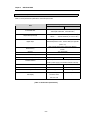
2.2
SPECIFICATIONS
Performance Specifications
Table 2.2 shows performance specifications of the RTD input module.
Specifications
Item
G3F-RD3A
G4F-RD2A
Pt 100 (JIS C1640-1989, DIN 43760-1980)
Connectable RTD
JPt100 (KS C1603-1991, JIS C1604-1981)
Temperature input range
Pt100
:
-200.0°C to 600°C (18.48 to 313.59Ω)
JPt100
:
-200.0°C to 600°C (17.14 to 317.28Ω)
Digital conversion value : 0 to 16,000
Digital output
Detected temperature value : -2000 to 6000 (one digit after
point ✕ 10)
Each of three wires at every channel has detection
Buffer memory
function.
Accuracy
±0.5 %(full scale)
Maximum conversion speed
50ms per channel
Number of temperature input device points
Insulation method
8 channels per module
4 channels per module
Photo-coupler insulation between the input
terminal and
the PLC power supply (non-insulation between channels)
Connection terminal block
38-point terminal block
20-point terminal block
Internal current consumption
0.5 A
0.45A
Weight
630 g
350 g
Output of the temperature
LED display
conversion value
and error code
[Table. 2.2 Performance Specifications]
2-2
-
Chapter 2.
2.3
SPECIFICATIONS
Names of Parts and Functions
The following gives names of parts.
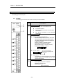
2.3.1
G3F-RD3A
The following gives the names and functions of each part of the G3F-RD3A.
No.
➀
Descriptions
RUN LED
It displays the operating status of G3F-RD3A module
On : Normal Operation
Flickering : Error occurred (For more information,
see Chapter 4.1
Off : DC 5V disconnection or the G3F-RD3A
!
module error
LED display
!
!
➁
!
Detected temperature value indication
Indication the temperature conversion value of the
channels enabled by the channel selection switch.
The detected temperature value is represented as
5-digit decimal number.
(Down to one place of a decimal number is
represented as a floating port number)
(Representation range : - 210.0°C to 610.0°C)
Representation example : -123.4°C
- 1 2 3. 4
!
Error No. display
E r
r
The rightmost
one bottom
The
onedigit
digitdispalys
displays the
the number
of error
number
of error
Stop Indication
This appears if a channel specified by the channel
selection switch is not specified as the used
channel in the program
Channel selection switch
!
➂
2-3
Used to specify the channel for detected
temperature value indication.
Setting range : 0 to 7
(8 to F are not used.)
Chapter 2.
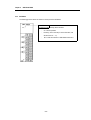
2.3.2
SPECIFICATIONS
G4F-RD2A
The following gives the names and functions of each part of the G4F-RD2A.
RUN LED
G4F-RD2A module operating status Indication
On : Normal operation
Flickering : Error occurred (For more information, see
Section Common
-
4.1)
Off : 5 VDC disconnection or G4F-RD2A module error
2-4
Chapter 2.
2.4
SPECIFICATIONS
RTD Input Module Characteristics
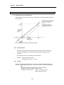
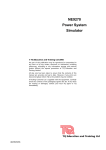
2.4.1 Temperature Conversion Characteristics
The RTD input module, as shown in the Fig. 2.1, linearlizes the non-linear characteristic resistance
input of the RTD.
Resistance
temperature
detection value
[Fig. 2.1] Temperature conversion characteristics( Pt100)
2.4.2
Conversion speed
The conversion speed of the RTD input module is 50 ms per channel and its processing is
processed sequentially, that is, one channel is processed and then another channel is
processed.
Processing time = 50 ms ✕ the number of the used channels
Example)
2.4.3
When three channels are used
Processing time = 50 ms ✕ 3 = 150 ms
Accuracy
The accuracy of RTD input module is within ±0.5 % of all of the measurable temperature range.
Example) When the RTD Pt100 is used, the conversion values of –100°C and 400°C are as
below.
Measurable temperature full range : 800°C (-200.0°C to 600.0°C)
Accuracy : 800 ✕ (±0.5%) = 800✕ (±0.005) = ±4°C
Temperature conversion range : - 104 °C to – 96 °C when –100°C
396°C to 404°C when 400°C
2-5
Chapter 2.
2.4.4
SPECIFICATIONS
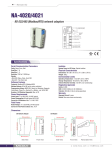
Burn-out Function
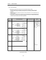
The RTD input module has the function of burn-out on the Pt100, JPt100 or cable.
1) As shown in the Fig. 2.2, if disconnection occurs in the RTD or cable then a voltage outside the
measurable range voltage is inputted by the internal burn-out circuit and burn-out error code is
generated.
2) The RTD input module can detect disconnection for each channel. But, burn-out is possible only in the
channels enabled.
3) If disconnection is detected in two or more wires, first, disconnection error code ‘b’ generated and then
disconnection error code a or b is generated sequentially. If disconnection is detected simultaneously
in A and B, only disconnection error code ‘b’ is generated.
Connection
Method
Connection Example
Burn-out Function
2-wire
Remark
- In 4-wire type, only all
type
terminal
wires marked '2'
connected to the
terminal block A are
all
detected
as
disconnection then
the A disconnection
error
can
be
detected.
3-wire
type
terminal
terminal
4-wire
type
No wiring
terminal
terminal
terminal block of
*1 : Pt
*2: Shield wire
[Fig. 2.2] Burn-out Area
2-6
Chapter 2.
2.5
SPECIFICATIONS
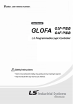
Connection between a Pt and RTD input module
Number of method of connection between Pt and RTD input module are three, that is, 2-wired type, 3wired type and 4-wired type.
The resistance of the wires used to connect Pt to RTD input module should be 10 Ω or less per wire.
The same wire (in thickness, length, and kind, etc.) should be used for each channel.
REMARK
✳
The difference between the resistance values of the wires used should be 1 Ω or less, or the accuracy
shown in the Table 2.2 could not be satisfied.
Connection
Connection Example
Method
Wire Conditions
2-wired type
➀ wire resistance10Ω
➁ wire resistance10Ω
➂ wire resistance10Ω
3-wired type
The difference between the
resistance values of the wires ➀ and
➁ : 1Ω or less
The difference between the
resistance values of the wires ➁ and
➂ : 1Ω or less
The difference between the
resistance values of the wires ➂
and ➀ : 1Ω or less
4-wired type
[Fig. 2.3]
Method of Connection between Pt and RTD Input Module
*1:
RTD (Pt100 or JPt1000)
*:2:
Shielded wire
2-7
Chapter 2.
SPECIFICATIONS
- The shields of the RTD and shields of wire should be connected to the FG of the RTD input
module.
2-8
Chapter 3.
INSTALLATION AND WIRING
Chapter 3.
3.1
INSTALLATION AND WIRING
Installation
3.1.1
Installation Ambience
This module has high reliability regardless of its installation environment, but be sure to check the
following for system reliability and stability.
1) Ambience requirements
Avoid installing this unit in locations which are subjected or exposed to :
- Water leakage and dust.
- Continuous shocks or vibrations.
- Direct sunlight.
- Dew condensation due to rapid temperature change.
- Higher or lower temperatures outside the range of 0 to 55 °C
2) Precautions during installing and wiring.
3.1.2
-
During drilling or wiring, do not allow any wire scraps to enter into the PLC.
-
Install it on locations that are convenient for operation.
-
Make sure that it is not located on the same panel that high voltage equipment located.
-
Make sure that the distance from the walls of duct and external equipment be 50 mm or more.
-
Be sure to be grounded to locations that have good ambient noise immunity.
Handling Precautions
From unpacking to installing the RTD input module, be sure to check the following:
1) Do not drop it off, and make sure that strong shock should not be applied.
2) Do not unload the PCB from its case. It can cause faults.
3) During wiring, be sure to check any foreign matter like wire scraps should not enter into the upper side
of the PLC. If any foreign matter has entered into it, always eliminate it.
4) Do not load or unload the module while the power supply is being connected.
3-1
Chapter 3.
3.2
INSTALLATION AND WIRING
Wring Precautions
1)
When connecting Pt with the RTD input module, refer to the Chapter 2.5 for wiring.
2)
Be sure to separate the external input signal of the RTD input module from an alternating current so
that surge or induction noise generated from the alternating current could not effect.
3)
When wiring, locating this unit too near from high temperature generating devices or materials or
contacting it with the material like oil can cause short-circuit and occur damage or disorder.
4)
When wiring to the terminal block, wiring with high-pressure wire or power supply wire can occur flow
inhibition and cause disorder or malfunction.
5)
Make sure that electric wires do not pass before the LED display. It causes the digital values not to be
identified.
3-2
Chapter 4.
TROUBLESHOOTING
Chapter 4.
TROUBLESHOOTING
The followings explain errors that could occur during operating the RTD input module and their
troubleshooting.
4.1
Errors Indicated by RUN LED Flickering
Errors indicated by the flickering RUN LED of RTD input module are given below.
RUN LED Status
Flickering
(cycle: 0.1 sec)
Flickering
(cycle: 0.2 sec)
Flickering
(cycle: 0.6 sec)
Flickering
(cycle: 1.0 sec)
Descriptions
WDT error
G3F-RD3A LED display
Err 1
System error
Internal memory error
A/D conversion error
Err 0
Err 2
Err 3
A disconnection detected
B disconnection detected
b disconnection detected
Outside the upper or lower
bound of the range
Err 4
Err 5
Err 6
Err 7
4-1
Remark
The data before
error has
occurred is
maintained.
Chapter 4.
4.2
TROUBLESHOOTING
Troubleshooting Procedure
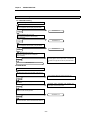
4.2.1 RUN LED Flickering
RUN LED flickering
RUN LED flickering with 0.1 sec cycle
'Err 0' is displayed in the LED display(Only G3F-RD3A)
Yes
See Section 4.2.5
No
RUN LED flickering with 0.2 sec cycle.
'Err 1' or 'Err 2' is displayed in the LED display
(Only G3F-RD3A)
Yes
See Section 4.2.5
No
RUN LED flickering with 0.6 sec cycle.
'Err 3' is displayed in the LED display. (Only G3F-RD3A)
Yes
See Section 4.2.5
No
RUN LED flickering with 1 sec cycle.
One of 'Err4','Err5','Err6' and Err7' is displayed
(Only G3F-RD3A)
Disconnection is detected between the temperaturemeasuring register and RTD input module, or temperature
is outside the range(-200.0°C~600.0°C) See GM Section
7.2
Yes
No
See Section 4.2.5
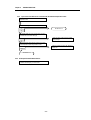
4.2.2 RUN LED Off
RUN LED off
The RTD input module is correctly loaded on the base unit.
Load correctly the RTD input module on the base unit.
No
Yes
The capacity of the power supply module on the base unit
is sufficient.
.
Re-examine system configuration with calculating the
consumption current of each module.
No
Yes
If the RTD input module which has error is replaced with
another one, then normally operated.
See Section 4.2.5
Yes
No
Fault of other module, not the RTD input module.
For more information, see the CPU Module User's Manual.
4-2
Chapter 4.
4.2.3
TROUBLESHOOTING
Detected Temperature Value Unreadable from the CPU Module.
CPU module cannot read the temperature conversion value.
RUN LED is turned off.
See Section 4.2.2
Yes
No
RUN LED is flickering
See Section 4.2.1
Yes
No
The use channels are correctly specified.
Check the use channels and correctly specify them.
No
Yes
Wires are correctly connected to the specified channel.
Perform correctly the wiring with referring to
Section 2.5.
No
Yes
Replacing the RTD input module with another one correct
the temperature conversion value.
See Section 4.2.5
Yes
No
The base unit hardware defect
See Section 4.2.5
4-3
Chapter 4.
4.2.4
TROUBLESHOOTING
Input value of the RTD is not consistent with the detected temperature value.
Input value of the RTD is not consistent with the detected
temperature value.
RUN LED is flickering.
See Section 4.2.2
Yes
No
The specified RTD type for the corresponding channel is
consistent with the connected RTD type
Check the type of the RTD and correctly
specify the type
No
Yes
The wiring between the temperature resister input module
and the temperature-measuring resister is correct..
Perform correctly the wiring with referring to
Section 2.5
No
Yes
See Section 4.2.5
4.2.5
RTD Input Module Hardware Defect
RTD input module hardware defect.
Contact the nearest agency or service station
4-4
Chapter 5.
DIMENSIONS
Chapter 5.
5.1
DIMENSIONS
G3F-RD3A Dimensions
5-1
Chapter 5.
5.2
DIMENSIONS
G4F-RD2A Dimensions
5-2
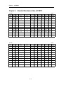
Chapter 6.
APPENDIX
Chapter 6. Standard Resistance Value of Pt/RTD
Unit : Ω
Pt 100Ω
-200
-100
-0
Temperature
(°°C)
Temperature
(°°C)
0
100
200
300
400
500
600
18.49
60.25
100.00
-0
0
100.00
138.50
175.84
212.02
247.04
280.90
313.59
56.19
96.09
-10
10
103.90
142.29
179.51
215.57
250.48
284.22
52.11
92.16
-20
20
107.79
146.06
183.17
219.12
253.90
287.53
48.00
88.22
-30
30
111.67
149.82
186.82
222.65
257.32
290.83
43.87
84.27
-40
40
115.54
153.58
190.45
226.17
260.72
294.11
39.71
80.31
-50
50
119.40
157.31
194.07
229.67
264.11
297.39
35.53
76.33
-60
60
123.24
161.04
197.69
233.17
267.49
300.65
31.32
72.33
-70
70
127.07
164.76
201.29
236.65
270.86
303.91
27.08
68.33
-80
80
130.89
168.46
204.88
240.13
274.22
307.15
22.80
64.30
-90
90
134.70
172.16
208.45
243.59
277.56
310.38
Temperature
(°°C)
0
100
200
300
400
500
600
317.28
Unit : Ω
Jpt 100Ω
-200
-100
-0
Temperature
(°°C)
17.14
59.57
100.00
-0
0
100.00
139.16
177.13
213.30
249.56
284.02
55.44
96.02
-10
10
103.97
143.01
180.86
217.54
253.06
284.40
51.29
92.02
-20
20
107.93
146.85
184.58
221.15
256.55
290.77
47.11
88.01
-30
30
111.88
150.67
188.29
224.74
260.02
294.12
42.91
83.99
-40
40
115.81
154.49
191.99
228.32
263.49
297.47
38.68
79.96
-50
50
119.73
158.29
195.67
231.89
266.94
300.80
34.42
75.91
-60
60
123.64
162.08
199.35
235.45
270.38
304.12
30.12
71.85
-70
70
127.54
165.86
203.01
238.99
273.80
307.43
25.80
67.77
-80
80
131.42
169.63
206.66
242.53
277.22
310.72
21.46
63.68
-90
90
135.30
173.38
210.30
246.05
280.63
314.01
6-1
Chapter 7.
FUNCTION BLOCKS
Chapter 7.
FUNCTION BLOCKS
The followings explain the function blocks for the RTD input module used in GMWIN
The types of function block are given here.
G3F-RD3A
G4F-RD2A
No.
Function
Local
Remote
Local
Remote
1
RTD3INI
RTDR3INI
RTD2INI
RTDR2INI
Module Initialization
Reading the detected temperature value
2
RTD3ARD RTDR3RD RTD2ARD RTDR2RD
(Array type)
Reading the detected temperature value
3
RTD3RD
RTD2RD
(Single type)
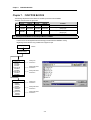
7.1
Inserting Function Blocks for the RTD Input Module in GMWIN.
Function blocks can be registered with the following procedure while the GMWIN is running.
Registering function blocks is only possible when a project is open.
Project(P)
Selection
Library Insert(I)
G3F-RD3A
1. Special. 3fb
• RTD3INI
• RTD3ARD
• RTD3RD
2. Remote3.3fb
• RTDR3INI
• RTDR3RD
3. Remote4.3fb
• RTDR3INI
• RTDR2RD
G4F-RD2A
1. Special. 4fb
• RTD2INI
• RTD2ARD
• RTD2RD
2. Remote4.4fb
• RTDR2INI
• RTDR2RD
3. Remote3.4fb
• RTDR3INI
• RTDR3RD
Inserting local
function block
Inserting GM3 remote
function block
Inserting GM4 remote
function block
Inserting local
function block
Inserting GM4 remote
function block
Inserting GM3 remote
function block
7-1
Chapter 7.
7.2
FUNCTION BLOCKS
Local Function Blocks
7.2.1 Module Initialization (G3F-RD3A: RTD3INI, G4F-RD2A:RTD2INI)
Module initialization function block specifies RTD input module base location, slot location, run channel
enable/disable and the type of RTD for use in program.
Function
Block
I/O
Variable
Data
Type
Descriptions
REQ
BOOL
Function block execution request area
- Used to request an execution of the initialization function block
- If the conditions connected with this area are established while program is
running and input condition changes from low to high, the initialization function
block is executed
BASE
USINT
Base location No.
- Used to write the number of the base where the RTD input module is loaded.
- Setting range: GM1 series(0~31), GM2 series(0~7), GM3/4 series(0-3)
SLOT
USINT
Slot location No.
- Used to write the number of the slot where the RTD input module is loaded.
- Setting range: 0~7
CH
BOOL
[Array]
*Note 1
Run channel enable/disable specification
- Used to enable or disable a channel for run.
- Specify “1” for enabling, and “0” for disabling
TYPE
BOOL
[Array]
*Note 1
Specifying the type of RTD for use
- Used to specify the type of “0” for Pt100 and “1” for JPt100 for each channel
"0" :Pt100
"1" : JPt100
BOOL
Function block execution complete status
- “1” is output when the initialization function block is finished with no error and
“1” remains until next execution. If an error occur, ‘0’ is displayed and the
operation enters into the stop state.
STAT
USINT
Error status indication area
- Used to output the number of an error when it occurs during initialization function
block execution.
- For description of errors, see GM Section 7.4
ACT
BOOL
[Array]
*Note 1
Run channel status indication area
- After the initialization function block is finished with no error, “1” is output if the
channel is in normal state. But “0” is output for the disabled channels.
I
O
DONE
REMARK
Note 1: The numbers of Array are 8 in G3F-RD3A, 4 in G4F-RD2A.
7-2
Chapter 7.
7.2.2
FUNCTION BLOCKS
Reading the Detected Temperature Value of the Module (Array Type)
(G3F-RD3A : RTD3ARD, G4F-RD2A : RTD2ARD)
The Array type temperature conversion value reading function block executes all channels of the RTD
input module in a batch processing. If a channel is enabled then the function block outputs the detected
temperature value and its digital conversion value that is usable as a PV in the PID control module.
Function
Block
I/O
I
O
Variable
Data
Type
REQ
BOOL
BASE
USINT
SLOT
USINT
CH
DONE
BOOL
[Array]
*Note 1
BOOL
STAT
USINT
ACT
BOOL
[Array]
*Note 1
BOOL
[Array]
*Note 1
USINT
[Array]
*Note 1
INT
[Array]
*Note 1
ALM
ALM_
CODE
TEMP
SCAL
INT
[Array]
*Note 1
Descriptions
Function block execution request area
- Used to request an execution of the reading function block
- If the conditions connected with this area are established while the program is
running and “0” changes into “1”, the reading function block is executed.
Base location No.
- Used to write the number of the base where the RTD input module is loaded.
- Setting range: GM1 series(0~31), GM2 series(0~7), GM3/4 series(0-3)
Slot location No.
- Used to write the number of the slot where the RTD input module is loaded.
- Setting range: 0~7
Run channel enable/disable specification
- Used to enable or disable a channeI for run.
- Specify “1” for enabling, and “0” for disabling
Function block execution complete status
- “1” is output when the reading function block is finished with no error and “1”
remains until next execution. If an error occur, ‘0’ is displayed and the operation
enters into the stop state.
Error status indication area
- Used to output the number of an error when it occurs during reading function
block execution.
- For description of errors, see GM Section 7.4
Run channel status indication area
- After the reading function block is finished with no error, “1” is output if the
channel is in normal state. But “0” is output for the disabled channels.
Run channel error indication area
- “1” is outputted when error occurs for each run channel.
Run channel error code area
- Used to output the code of error occurred during run for each channel.
- For error description, see GM Section 7.4.
Detected temperature value output area
- The CPU module reads the detected temperature value(-200.0°C to +600.0°C) of
the corresponding channel from the RTD input module and outputs it to this area.
- The detected temperature value of each channel is 10 times than the real
temperature value.
- (Example: Detected temperature value 1234 → real temperature value 123.4°C)
Digital conversion value output area
- The CPU module reads the digital conversion of the corresponding channel from
the RTD input module and outputs it to this area.
- The detected temperature value (-200.0°C to +600.0°C) of each channel is
converted into the a digital value within 0 to 16000 and it is output to this area.
- Value to be read from the output variable.
• SCAL =(the value to be read from the output variable TEMP + 2000) ✕ 2
• Example: Where a temperature is 234.5°C.
The value to be read from the TEMP is (temperature ✕ 10), then
2345 is the detected temperature value.
The value to be read from the SCAL is (2345 + 2000) ✕ 2, i.e.,
8690.
- The output value converted into a digital value can be used as the PV of the PID
control module.
REMARK
Note 1: The numbers of Array are 8 in G3F-RD3A, 4 in G4F-RD2A.
7-3
Chapter 7.
7.2.3
FUNCTION BLOCKS
Reading the Detected Temperature Value of the Module (Single Type)
(G3F-RD3A : RTD3RD, G4FRD2A : RTD2RD)
The stand-alone type Temperature conversion value reading function block processes only one channel
of the RTD input module. If a channel is enabled then the function block outputs the detected
temperature value and its digital conversion value that is usable as a PV in the PID control module.
Function
Block
I/O
I
O
REQ
Data
Type
BOOL
BASE
USINT
SLOT
USINT
CH
USINT
DONE
BOOL
STAT
USINT
ALM
BOOL
TEMP
IN T
SCAL
INT
Variable
Descriptions
Function block execution request area
- Used to request an execution of the reading function block
- If the conditions connected with this area are established while the
program is running and “0” changes into “1”, the reading function block
is executed.
Base location No.
- Used to write the number of the base where the RTD input module is
loaded.
- Setting range: GM1 series(0~31), GM2 series(0~7), GM3/4 series(0-3)
Slot location No.
- Used to write the number of the slot where the RTD input module is
loaded.
- Setting range: 0~7
Area for specifying the used channel.
Settings : G3F-RD3A: 0 to 7, G4F-RD2A: 0 to 3
Function block execution complete status
- “1” is output when the reading function block is finished with no error and
“1” remains until next execution. If an error occur, ‘0’ is displayed and the
operation enters into the stop state.
Error status indication area
- Used to output the number of an error when it occurs during reading
function block execution.
- For description of errors, see GM Section 7.4
Run channel error indication area
- “1” is output if error occurs for each run channel.
Detected temperature value output area
- The CPU module reads the detected temperature value(-200.0°C to
+600.0°C) of the corresponding channel from the RTD input module and
outputs it to this area.
- The detected temperature value of each channel is 10 times than the real
temperature value.
(Example: Detected temperature value 1234 → real temperature value
123.4°C)
Digital conversion value output area
- The CPU module reads the digital conversion of the corresponding
channel from the RTD input module and outputs it to this area.
- The detected temperature value (-200.0°C to +600.0°C) of each channel
is converted into a digital value within 0 to 16000 and it is output to this
area.
- Value to be read from the output variable.
• SCAL =(the value to be read from the output variable TEMP + 2000)
✕2
• Example: Where a temperature is 234.5°C.
The value to be read from the TEMP is (temperature ✕
10), then
2345 is the detected temperature value.
The value to be read from the SCAL is (2345 + 2000) ✕ 2,
i.e., 8690.
- The output value converted into a digital value can be used as the PV of
the PID control module.
7-4
Chapter 7.
FUNCTION BLOCKS
7.3 Remote Function Block
7.3.1
Module Initialization (G3F-RD3A : RTDR3INI,
G4F-RD2A : RTDR2INI)
The module initialization function block specifies, for use in the program, the location No. of the slot
where the communication module loaded in the receiving station, the station No. of the communication
module loaded in the remote I/O station, the No. of the base where the RTD input module is loaded, the
use channels and the type of the RTD.
Function
Block
I/O
I
REQ
Data
Type
BOOL
NET_NO
USINT
ST-NO
USINT
BASE
USINT
SLOT
USINT
CH
NDR
BOOL
[Array]
*Note 1
BOOL
[Array]
*Note 1
BOOL
ERR
BOOL
STAT
USINT
ACT
BOOL
[Array]
*Note 1
Variable
TYPE
O
Descriptions
Function block execution request area at rising edge.
- Used to request an execution of the reading function block
- If the conditions connected with this area are established while the
program is running and “0” changes into “1”(rising edge), the module
initialization function block is executed.
Location No. of the slot where the communication module of the station to
which the function block will be sent is loaded.
- Setting range: 0 ~ 7
Station No. of the communication module loaded in the remote I/O station.
- Setting range: 0 ~ 63
Base module location No.
- Used to write the number of the base where the RTD input module is
loaded.
- Setting range: 0 ~ 3
Slot location No.
- Used to write the number of the slot where the RTD input module is
loaded.
- Setting range: 0~7
Run channel enable/disable specification
- Used to enable or disable a channel for run.
- Specify “1” for enabling, and “0” for disabling
Specifying the type of RTD for use
- Used to specify the type of “0” for Pt100 and “1” for JPt100 for each
channel
“1” when the function block is finished without error. “1” remains during the
scan where the execution condition is being satisfied and it changes into
“0” at the next scan.
Error information indication area
- If error occurs during initialization function block execution “1” is output
and the module enter into the stop state. “1” remains during the scan
where the execution condition is being satisfied and it changes into “0” at
the next scan.
Error status indication area
- Used to output the number of an error when it occurs during reading
function block execution.
- For description of errors, see GM Section 7.4
Run channel status indication area
- After the initialization function block is finished with no error, “1” is output
if the channel is in normal state. But “0” is output for the disabled
channels.
REMARK
Note 1: The numbers of Array are 8 in G3F-RD3A, 4 in G4F-RD2A.
7-5
Chapter 7.
FUNCTION BLOCKS
7.3.2 Reading the Detected Temperature Value of the Module
(G3F-RD3A : RTDR3RD, G4F-RD2A : RTDR2RD)
The module temperature conversion value reading function block specifies the location No. of the slot where the communication
module loaded in the receiving station, the station No. of the communication module loaded in the remote I/O station If also
processes all channels in block. The enabled channel outputs the temperature conversion value and its digital conversion value that
can be used as the PV in the PID control module, and the two values are used in the program.
Function
Data
I/O
Variable
Descriptions
Block
Type
I
REQ
BOOL
Function block execution request area (at the ascending edge)
- Used to request an execution of the reading function block
- If the conditions connected with this area are established while the program is running
and “0” changes into “1(rising edge)”, the module reading function block is executed.
NET_N
USINT
Location No. of the slot where the communication module of the station to which the
O
function block will be sent is loaded.
- Setting range: 0 ~ 7
ST-NO
USINT
Station No. of the communication module loaded in the remote I/O station.
-Setting range: 0 ~ 63
BASE
USINT
Base module location No.
- Used to write the number of the base where the RTD input module is loaded.
- Setting range: 0 ~ 3
SLOT
USINT
Slot location No.
- Used to write the number of the slot where the RTD input module is loaded.
- Setting range: 0~7
CH
BOOL
Run channel enable/disable specification
[Array]
- Used to enable or disable a channel for run.
*Note 1
- Specify “1” for enabling, and “0” for disabling
O
NDR
BOOL
“1” when the function block is finished without error. “1” remains during the scan where
the execution condition is being satisfied and changes into “0” at next scan.
ERR
BOOL
Error information indication area
- If error occurs during reading function block execution “1” is outputted and the module
enter into the stop state. “1” remains during the scan where the execution condition is
being satisfied and it changes into “0” at the next scan.
STAT
USINT
Error status indication area
- Used to output the number of an error when it occurs during reading function block
execution.
- For description of errors, see GM Section 7.4
ACT
BOOL
Run channel status indication area
[Array]
- After the reading function block is finished with no error, “1” is output if the channel is in
*Note 1
normal state. But “0” is output for the disabled channels.
ALM
BOOL
Run channel error indication area
[Array]
- “1” is outputted when error occurs for each run channel.
*Note 1
ALM_
USINT
Run channel error code area
CODE
[Array]
- Used to output the code of error occurred during run for each channel.
*Note 1
- For error description, see GM Section 7.4.
TEMP
INT
Detected temperature value output area
[Array]
- The CPU module reads the detected temperature value(-200.0°C to +600.0°C) of the
*Note 1
corresponding channel from the RTD input module and outputs it to this area.
- The detected temperature value of each channel is 10 times than the real temperature
value.
- (Example: Detected temperature value 1234 → real temperature value 123.4°C)
SCAL
INT
Digital conversion value output area
[Array]
- The CPU module reads the digital conversion of the corresponding channel from the
*Note 1
RTD input module and outputs it to this area.
- The detected temperature value (-200.0°C to +600.0°C) of each channel is
converted into the a digital value within 0 to 16000 and it is outputted to this area.
- Value read from the output variable, SCAL = (the value read the output variable
TEMP + 2000) ✕ 2
• Example: Where a temperature is 234.5°C.
The value read from the TEMP Is (temperature ✕ 10), then
2345 is the detected temperature value.
The value read form the SCAL is (2345 + 2000) ✕ 2, i.e., 8690.
- The output value converted into a digital value can be used as the PV of the PID
control module.
REMARK
Note 1: The numbers of Array are 8 in G3F-RD3A, 4 in G4F-RD2A.
7-6
Chapter 7.
FUNCTION BLOCKS
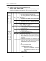
7.4 Errors on Function Block
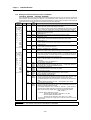
7.4.1 Errors Indicated by the Output Variable STAT
Errors indicated the output variable STAT and their corrective actions are explained.
STAT
No.
Item
0
Local
Function Block
InitialiReading
zation
Array Stand
-alone
Ο
Ο
Ο
Descriptions
Normal run status
Ο
Ο
Ο
Ο
Ο
Ο
Ο
Ο
Ο
Ο
Ο
Ο
Ο
Ο
Ο
Ο
Ο
Ο
Ο
Ο
Ο
Ο
Ο
Ο
Ο
Ο
B disconnection detected at the use channels
Ο
18
b disconnection detected at the use channels.
A and B disconnection detected simultaneously.
Ο
19
Temperature outside the range at the use
channels
Ο
Remote communications module H/W defect
Base location No. outside the setting range
Slot location No. outside the setting range
Ο
Ο
Ο
Ο
Ο
Ο
Other module, not RTD input module, is loaded
RTD input module hardware defect
RTD input module memory defect
The run channel was not specified in the
Initialization function block.
Disconnection detected at one or more of the
use channels, or temperature outside the range.
Ο
Ο
Ο
Ο
Ο
Ο
Ο
Ο
1
2
3
Base location No. outside the setting range
The corresponding base unit hardware defect
Slot location No. outside the setting range
4
The specified slot has no RTD input module
5
16
A module other than RTD input module is loaded
on.
Channel No. outside the setting range
RTD input module hardware defect
RTD input module memory defect
The run channel was not specified in the
Initialization function block.
Disconnection detected at one or more of the
use channels, or temperature outside the range.
A disconnection detected at the use channels
17
6
7
8
9
10
128
129
131
Remote
133
135
136
137
138
Corrective Action
Adjust it within the setting range (See GM Section 7.2)
Contact a service station
Specify correctly the numbers of the slot where the
RTD module is loaded .
Load RTD input module on the specified slot.
Load RTD input module on the specified slot.
Specify correctly the No. of the run channel.
Contact a service station.
Contact a service station.
Specify correctly run channels in the initialization
function block.
See GM Section 7.4.2.
Fix the A terminal disconnection between the RTD
input module and the temperature-measuring resistor
Fix the B terminal disconnection between the RTD
input module and the temperature-measuring resistor
Fix the disconnection between the b terminal RTD
input module and the temperature-measuring resistor.
Or, Fix A and B terminals disconnection.
Correctly specify the type of the temperaturemeasuring resistor, or use the temperature within the
range (-200.0°C ~ 600.0)°
See Remote communications module User’s Manual
Adjust it within the setting range (See GM Section 7.2)
Specify correctly the numbers of the slot where the
RTD Input module is loaded.
Load RTD input module on the specified slot.
Contact a service station.
Contact a service station.
Specify correctly run channels in the initialization
function block.
See GM Section 7.4.2.
7.4.2 Errors Indicated by the Output Variable ALM_CODE in the Array Type Detected Temperature Value Reading
Function Block. (G3F-RD3A : RTD3ARD, RTDR3RD. G4F-RD2A : RTD2ARD, RTDR2RD)
ALM_CODE No.
Descriptions
0
16
17
Normal run status
A disconnection detected
B disconnection detected
b disconnection detected, A and B
disconnection detected simultaneously.
Fix the A disconnection between RTD input module and RTD.
Fix the A disconnection between RTD input module and RTD
Temperature outside the range
Correctly specify the type of the RTD, or use the temperature within the range (-200.0°C ~ 600.0°C)
18
19
Corrective Action
Fix the A disconnection between RTD input module and RTD. Or, Fix the A and B disconnection.
7-7
Chapter 8.
PROGRAMMING
Chapter 8.
8.1
PROGRAMMING
A Program for Output of the Detected Temperature Value as a BCD Value
1) System Configuration
The lamp turns on when
the detected temperature
value is negative
2) Initial Settings
(1) Specifying the used channel: channel 0
(2) Specifying the type of the RTD : Pt 100
3) Descriptions of the Program
The present A/D conversion value of the detected temperature value which is detected from the
temperature-measuring resistor Pt 100 is displayed on the BCD digital display by use of channel 0 of the
temperature-measuring resistor input module. The lamp turns on when the detected temperature value is
a negative number and turns off when it is a positive number.
8-1
Chapter 8.
PROGRAMMING
4) Program
Turns "ON" when
the function blocks
off the RTD input
module
In this program, %Q0.2.0 turns on
when the temperature value read
through channel 0 is a negative
number and the temperature value
of the negative temperature value
number is converted into positive.
In this program, The data type of the detected temperature value is integer so that it is converted into a BCD data
type to be displayed to the digital BCD value is output %Q0.1.0 to %Q0.1.19
8-2
Chapter 8.
PROGRAMMING
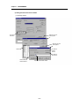
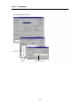
5) Setting the initial values of I/O variables
(1) specifying channel
This denotes
8 channels
Select this and this
screen appears.
Select this and this
screen appears.
Channel No.
To select the
previous
channel
To select the
next channel
Channel enable : 1
Channel disable : 0
To specify channel enable/ disable
8-3
Chapter 8.
PROGRAMMING
(1)
(2) Specifying the type of the RTD
Channel No.
0 : Pt100
1 : JPt100
Specify Pt100 or JPt100
8-4
Chapter 8.
PROGRAMMING
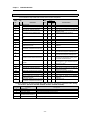
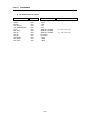
6) I/O variables used in the program
Variable Name
ALARM
BUFFER
CHO_DIGITAL
CHO_TEMPERATURE
PT100
RTD_ACTO
RTD_CH
RTD_INI
RTD_RD
RTD_READY
RTD_STATO
RTD_STAT1
Var_Kind
: VAR
: VAR
: VAR
: VAR
: VAR
: VAR
: VAR
: VAR
: VAR
: VAR
: VAR
: VAR
Data
Type
: BOOL
: DINT
: INT
: INT
ARRAY[0..7] OF BOOL
ARRAY[0..7] OF BOOL
ARRAY[0..7] OF BOOL
FB Instance
FB Instance
: BOOL
: USINT
: USINT
8-5
(AT Address) (Initial Value)
: = { 0, 0, 0, 0, 0, 0, 0, 0}
: = { 1, 0, 0, 0, 0, 0, 0, 0}
Chapter 8.
8.2
PROGRAMMING
A Program for Conversing the Detected Temperature Value(°°C) into Fahrenheit(°°F) and Output as a
BCD Value
1) System
value
negative
2) Initial Settings
(1) Specifying the used channel : channel 0
(2) Specifying the type of a temperature - measuring resistor : Pt 100
3) The Expression that Converts the Detected Temperature Value into a Fahrenheit
Detected temperature value = real temperature value x 10
Fahrenheit temperature
= real temperature x 1.8 + 32
=
=
Detected temperature value
x 1.8 +32
10
Detected temperature value x 18 + 320
10
∴ If the Fahrenheit temperature displayed on the BCD digital display is represented as 'the real
Fahrenheit temperature x 10', "the detected temperature x 18 + 320" be processed into the program.
4) Descriptions of the Program
(1) If %10.0.0 turns on then the initialization of the RTD input module is executed.
(2) The detected temperature value is displayed on %Q0.2.0 to %Q0.2.19 of the BCD digital display when
it is negative the ramp %Q0.3.2 turns on
(3) The detected temperature value is converted into a Fahrenheit temperature value and displayed
on %Q0.4.0 to %Q0.4.19 of the BCD digital display when it is negative the ramp %Q0.3.0 turns on.
(4) If disconnection is detected during temperature conversion at channel 0, The Lamp %Q0.3.1 turns on.
8-6
Chapter 8.
PROGRAMMING
5) Program
Initialization
command for
the
RTD
input module
Request
for
operation of the
reading function
block when it
has not been
operated
Loaded
base No.
Loaded
slot No.
Specifying used
channel
Indicating the error
status during initialization
function block execution
Base No.
Indicating the run
channel during initialization
function block execution.
Specifying the
type or RTD
The
temperature
detection is
normally
finished at
the
RTD
input module
Turns "On"
when error is
detected at
the
used
channel
Slot No.
Used
channel
Indicating the error
status
during
reading
function
block execution
Turns "On" when
error occurs at the
used channel
The
detected
temperature value
of channel 0
The
digital
conversion value of
channel 0
%Q0.3.2 turns on when the
detected temperature value of
centigrade is negative, and the
negative is converted into
positive.
In this routine, the data type of the
detected temperature value is
integer , so that it is covered into
BCD data type to be displayed to the
digital BCD value is output %Q0.2.0
to %Q0.2.19.
This
routine
converts
the
detected
temperature value
into a value of
Fahrenheit
%Q0.3.0 turns "On" when the temperature
converted into a value of Fahrenheit and a
negative is converted into a positive
In this routine, the data type of the
detected temperature value is
integer, so that it is covered into
BCD data type to be displayed to
the digital BCD value is
output %QD0.4.0~%QD0.4.19.
8-7
Chapter 8.
PROGRAMMING
6) I/O variables used in the Program
Variable Name
ACTO
ALARM
BUFFER0
BURRER1
DATAO
F_DATA
F_DATA1
F_DATA2
F_DATA3
INTIAL
PT100
RD_STAT
READ
RTD_CH
SCALEO
STATO
Var_Kind
: VAR
: VAR
: VAR
: VAR
: VAR
: VAR
: VAR
: VAR
: VAR
: VAR
: VAR
: VAR
: VAR
: VAR
: VAR
: VAR
Data
Type
: ARRAY [0..7] OF BOOL
: BOOL
: DINT
: DINT
: INT
: INT
: INT
: INT
: INT
: FB Instance
: ARRAY [0..7] OF BOOL
: USINT
: FB Instance
: ARRAY [0.77] OF BOOL
: INT
: USINT
8-8
(AT Address) (Initial Value)
: = { 0, 0, 0, 0, 0, 0, 0, 0}
: = { 1, 0, 0, 0, 0, 0, 0, 0}
Chapter 8.
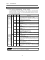
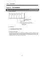
8.3
PROGRAMMING
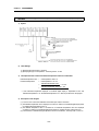
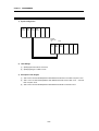
A Program when Loading the RTD Input Module onto the Remote I/O Station
1) System Configuration
GM3PA1A
GM3CPUA
G3LFUEA
G3QRY2A
Remote
Station No.
"0"
GM3PA1A
G3SRBEA
Slot 0
G3FRD3A
2) Initial Settings
(1) Specifying the used channel : channel 0
(2) Specifying the type of a RTD : Pt 100
3) Descriptions of the Program
(1) %Q0.1.0 turns on when the temperature value detected at channel 0 is more than or equal to -10°C
(2) %Q0.1.1 turns on when the temperature value detected at channel 0 is less than -10°C and more
than or equal to -20°C
(3) %Q0.1.2 turns on when the temperature value detected at channel 0 is less than -20°C
8-9
Chapter 8.
PROGRAMMING
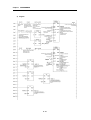
4) Program
The RTD input module
Base No. of the RTD
Input module.
Slot location No. of
the RTD input module
R
No
RTD input module
RTD input module
Specifying the used
channel
8 - 10
Chapter 8.
PROGRAMMING
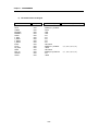
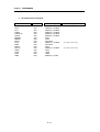
7) I/O variables used in the Program
Variable Name
ACTO
ACT1
ALARM
ALARM_NO
DIGITAL
ERROR0
ERROR1
INITIAL
PT100
READ
READY
RTD_CH
START
STAT0
STAT1
TEMP
Var_Kind
: VAR
: VAR
: VAR
: VAR
: VAR
: VAR
: VAR
: VAR
: VAR
: VAR
: VAR
: VAR
: VAR
: VAR
: VAR
: VAR
Data
Type
: ARRAY [0..7] OF BOOL
: ARRAY [0..7] OF BOOL
: ARRAY [0..7] OF BOOL
: ARRAY [0..7] OF BOOL
: ARRAY [0..7] OF BOOL
: BOOL
: BOOL
: FB Instance
: ARRAY [0..7] OF BOOL
: FB Instance
: BOOL
: ARRAY [0..7] OF BOOL
: BOOL
: USINT
: USINT
: ARRAY [0..7] OF INT
8 - 11
(AT Address) (Initial Value)
: = { 0, 0, 0, 0, 0, 0, 0, 0}
: = { 0, 0, 0, 0, 0, 0, 0, 0}