1
CTRIO
High-Speed Counter
Module
Manual Number: H24-CTRIO-M
MANUAL REVISIONS
Please include the Manual Number and the Edition, both shown below, when
communicating with us regarding this publication.
Title: CTRIO High-Speed Counter Module Installation and Operation
Manual Number: H24-CTRIO-M
Issue
Date
Description of Changes
Original
9/01
First Edition
WARNING
Thank you for purchasing automation equipment from Automationdirect.com™. We want your
new automation equipment to operate safely. Anyone who installs or uses this equipment should
read this publication (and any other relevant publications) before installing or operating the
equipment.
To minimize the risk of potential safety problems, you should follow all applicable local and
national codes that regulate the installation and operation of your equipment. These codes vary
from area to area and usually change with time. It is your responsibility to determine which codes
should be followed, and to verify that the equipment, installation, and operation are in compliance
with the latest revision of these codes.
At a minimum, you should follow all applicable sections of the National Fire Code, National
Electrical Code, and the codes of the National Electrical Manufacturer's Association (NEMA). There
may be local regulatory or government offices that can also help determine which codes and
standards are necessary for safe installation and operation.
Equipment damage or serious injury to personnel can result from the failure to follow all applicable
codes and standards. We do not guarantee the products described in this publication are suitable
for your particular application, nor do we assume any responsibility for your product design,
installation, or operation.
Our products are not fault-tolerant and are not designed, manufactured or intended for use or
resale as on-line control equipment in hazardous environments requiring fail-safe performance,
such as in the operation of nuclear facilities, aircraft navigation or communication systems, air
traffic control, direct life support machines, or weapons systems, in which the failure of the product
could lead directly to death, personal injury, or severe physical or environmental damage ("High
Risk Activities"). Automationdirect.com™ specifically disclaims any expressed or implied warranty
of fitness for High Risk Activities.
For additional warranty and safety information, see the Terms and Conditions section of our Desk
Reference. If you have any questions concerning the installation or operation of this equipment, or
if you need additional information, please call us at 770-844-4200.
This publication is based on information that was available at the time it was printed. At
Automationdirect.com™ we constantly strive to improve our products and services, so we reserve
the right to make changes to the products and/or publications at any time without notice and
without any obligation. This publication may also discuss features that may not be available in
certain revisions of the product.
Trademarks
This publication may contain references to products produced and/or offered by other companies.
The product and company names may be trademarked and are the sole property of their respective
owners. Automationdirect.com™ disclaims any proprietary interest in the marks and names of
others.
Copyright 2001, Automationdirect.com™ Incorporated
All Rights Reserved
No part of this manual shall be copied, reproduced, or transmitted in any way without the prior,
written consent of Automationdirect.com™ Incorporated. Automationdirect.com™ retains the
exclusive rights to all information included in this document.
AVERTISSEMENT
Nous vous remercions d'avoir acheté l'équipement d'automatisation de Automationdirect.comMC. Nous tenons à
ce que votre nouvel équipement d'automatisation fonctionne en toute sécurité. Toute personne qui installe ou
utilise cet équipement doit lire la présente publication (et toutes les autres publications pertinentes) avant de
l'installer ou de l'utiliser.
Afin de réduire au minimum le risque d'éventuels problèmes de sécurité, vous devez respecter tous les codes
locaux et nationaux applicables régissant l'installation et le fonctionnement de votre équipement. Ces codes
diffèrent d'une région à l'autre et, habituellement, évoluent au fil du temps. Il vous incombe de déterminer les
codes à respecter et de vous assurer que l'équipement, l'installation et le fonctionnement sont conformes aux
exigences de la version la plus récente de ces codes.
Vous devez, à tout le moins, respecter toutes les sections applicables du Code national de prévention des
incendies, du Code national de l'électricité et des codes de la National Electrical Manufacturer's Association
(NEMA). Des organismes de réglementation ou des services gouvernementaux locaux peuvent également vous
aider à déterminer les codes ainsi que les normes à respecter pour assurer une installation et un fonctionnement
sûrs.
L'omission de respecter la totalité des codes et des normes applicables peut entraîner des dommages à
l'équipement ou causer de graves blessures au personnel. Nous ne garantissons pas que les produits décrits dans
cette publication conviennent à votre application particulière et nous n'assumons aucune responsabilité à l'égard
de la conception, de l'installation ou du fonctionnement de votre produit.
Nos produits ne sont pas insensibles aux défaillances et ne sont ni conçus ni fabriqués pour l'utilisation ou la
revente en tant qu'équipement de commande en ligne dans des environnements dangereux nécessitant une
sécurité absolue, par exemple, l'exploitation d'installations nucléaires, les systèmes de navigation aérienne ou de
communication, le contrôle de la circulation aérienne, les équipements de survie ou les systèmes d'armes, pour
lesquels la défaillance du produit peut provoquer la mort, des blessures corporelles ou de graves dommages
matériels ou environnementaux («activités à risque élevé»). La société Automationdirect.comMC nie toute garantie
expresse ou implicite d'aptitude à l'emploi en ce qui a trait aux activités à risque élevé.
Pour des renseignements additionnels touchant la garantie et la sécurité, veuillez consulter la section Modalités et
conditions de notre documentation. Si vous avez des questions au sujet de l'installation ou du fonctionnement de
cet équipement, ou encore si vous avez besoin de renseignements supplémentaires, n'hésitez pas à nous
téléphoner au 770-844-4200.
Cette publication s'appuie sur l'information qui était disponible au moment de l'impression. À la société
Automationdirect.com, nous nous efforçons constamment d'améliorer nos produits et services. C'est pourquoi
nous nous réservons le droit d'apporter des modifications aux produits ou aux publications en tout temps, sans
préavis ni quelque obligation que ce soit. La présente publication peut aussi porter sur des caractéristiques
susceptibles de ne pas être offertes dans certaines versions révisées du produit.
Marques de commerce
La présente publication peut contenir des références à des produits fabriqués ou offerts par
d'autres entreprises. Les désignations des produits et des entreprises peuvent être des marques de
commerce et appartiennent exclusivement à leurs propriétaires respectifs.
Automationdirect.comMC nie tout intérêt dans les autres marques et désignations.
Copyright 2001, Automationdirect.comMC Incorporated
Tous droits réservés
Nulle partie de ce manuel ne doit être copiée, reproduite ou transmise de quelque façon que ce soit sans le
consentement préalable écrit de la société Automationdirect.comMC Incorporated. Automationdirect.comÔ
conserve les droits exclusifs à l'égard de tous les renseignements contenus dans le présent document.
TABLE OF CONTENTS
Table of Contents
Chapter 1: Introduction to the CTRIO Module
General Information about the CTRIO Module
CTRIO Workbench . . . . . . . . . . . . . . . . . . . . .
Supported CPUs . . . . . . . . . . . . . . . . . . . . . .
Typical Counter Applications: . . . . . . . . . . . . .
.
.
.
.
.
.
.
.
.
.
.
.
.
.
.
.
.
.
.
.
.
.
.
.
.
.
.
.
.
.
.
.
.
.
.
.
.
.
.
.
.
.
.
.
.
.
.
.
.
.
.
.
.
.
.
.
.
.
.
.
.
.
.
.
.
.
.
.
.
.
.
.
.
.
.
.
.
.
.
.
.
.
.
.
.
.
.
.
.
.
.
.
.
.
.
.
.
.
.
.
.1–2
.1–2
.1–2
.1–2
Specifications . . . . . . . . . . . . . . . . . . . . . . . . . . . . . . . . . . . . . . . . . . . . . . . . . . . .1–3
Chapter 2: Installation and Field Wiring
How to Install the CTRIO Module . . . . . . . . . . . . . . . . . . . . . . . . . . . . . . . . . . . .2–2
CPU and CTRIO Compatibility Chart . . . . . . . . . . . . . . . . . . . . . . . . . . . . . . . . . .2–2
Jumpers . . . . . . . . . . . . . . . . . . . . . . . . . . . . . . . . . . . . . . . . . . . . . . . . . . . . . . . .2–3
Wiring the CTRIO Module . . . . . . . . . . . . . . . . . . . . . . . . . . . . . . . . . . . . . . . . . .2–4
PNP Field Device . . . . . . . . . . . . . . . . . . . . . . . . . . . . . . . . . . . . . . . . . . . . . . . . .2–5
NPN Field Device . . . . . . . . . . . . . . . . . . . . . . . . . . . . . . . . . . . . . . . . . . . . . . . .2–5
Solid State Input Device Wiring . . . . . . . . . . . . . . . . . . . . . . . . . . . . . . . . . . . . . .2–5
Output Schematic . . . . . . . . . . . . . . . . . . . . . . . . . . . . . . . . . . . . . . . . . . . . . . . .2–6
Quadrature Encoder Wiring Example . . . . . . . . . . . . . . . . . . . . . . . . . . . . . . . . . .2–7
Stepper Drive Wiring Example . . . . . . . . . . . . . . . . . . . . . . . . . . . . . . . . . . . . . . .2–7
TTL Quadrature Encoder Field Wiring . . . . . . . . . . . . . . . . . . . . . . . . . . . . . . . . .2–8
TTL Input Wiring . . . . . . . . . . . . . . . . . . . . . . . . . . . . . . . . . . . . . . . . . . . . . . . . .2–9
Table of Contents
Chapter 3: CTRIO Workbench
What is CTRIO Workbench? . . . . . . . . . . . . . . . . . . . . . . . . . . . . . . . . . . . . . . . .3–2
Installing CTRIO Workbench . . . . . . . . . . . . . . . . . . . . . . . . . . . . . . . . . . . . . . . .3–2
Getting Started with CTRIO Workbench . . . . . . . . . . . . . . . .
Linking to CTRIO Module in DirectSOFT32 . . . . . . . . . . . . . .
Successful Connection . . . . . . . . . . . . . . . . . . . . . . . . . . . . .
Choose “Program Mode” to Configure the CTRIO Module . .
Choose “Run Mode” to Start Processing Pulses with the CTRIO
Using the Configure IO Dialog . . . . . . . . . . . . . . . . . . . . . . .
Supported Functions . . . . . . . . . . . . . . . . . . . . . . . . . . . . . .
.
.
.
.
.
.
.
.
.
..
..
.
.
.
.
.
.
.
.
.
.
.
.
.
.
.
.
.
.
.
.
.
.
.
.
.
.
.
.
.
.
.
.
.
.
.
.
.
.
.
.
.
.
.
.
.
.
.
.
.
.
.
.
.
.
.
.
.
.
.
.
.
.
.
.
.
.
.
.
.
.
.
.
.
.
.
.
.
.
.
.
.
.
.
.
.3–2
.3–3
.3–3
.3–4
.3–4
.3–5
.3–6
Input Function Selections . . . . . . . . . . . . . . . . . . . . . . . . . . . . . . . . . . . . . . . . . .3–7
Counter Function . . . . . . . . . . . . . . . . . . . . . . . . . . . . . . . . . . . . . . . . . . . . . . . .3–7
Quad Counter . . . . . . . . . . . . . . . . . . . . . . . . . . . . . . . . . . . . . . . . . . . . . . . . . .3–9
Pulse Catch . . . . . . . . . . . . . . . . . . . . . . . . . . . . . . . . . . . . . . . . . . . . . . . . . . .3–10
Edge Timer . . . . . . . . . . . . . . . . . . . . . . . . . . . . . . . . . . . . . . . . . . . . . . . . . . .3–11
Dual Edge Timer . . . . . . . . . . . . . . . . . . . . . . . . . . . . . . . . . . . . . . . . . . . . . . .3–12
Reset 1 and Reset 2 . . . . . . . . . . . . . . . . . . . . . . . . . . . . . . . . . . . . . . . . . . . . .3–14
A Word About Soft Resets . . . . . . . . . . . . . . . . . . . . . . . . . . . . . . . . . . . . . . . . .3–14
Introduction to the Scaling Wizard . . . . . . . . . . . . . .
Scaling Wizard Examples for Counter Functions . . . . .
Position Scaling (Counter) . . . . . . . . . . . . . . . . . . . .
Important Note About Rate Measurement Applications
Rate Scaling (Counter) . . . . . . . . . . . . . . . . . . . . . . .
Using the Scaling Wizard with Timer Functions . . . . .
Interval Scaling (Timer) . . . . . . . . . . . . . . . . . . . . . .
....
....
....
...
....
....
....
.
.
.
.
.
.
.
.
.
.
.
.
.
.
.
.
.
.
.
.
.
.
.
.
.
.
.
.
.
.
.
.
.
.
.
.
.
.
.
.
.
.
.
.
.
.
.
.
.
.
.
.
.
.
.
.
.
.
.
.
.
.
.
.
.
.
.
.
.
.
.
.
.
.
.
.
.
.
.
.
.
.
.
.
.
.
.
.
.
.
.
.
.
.
.
.
.
.
.
.
.
.
.
.
.
.3–16
.3–16
.3–17
.3–18
.3–18
.3–19
.3–19
Using the Monitor I/O Dialog . . . . . . . . . . . . . . . . . . . . . . . . . . . . . . . . . . . . . .3–20
Discrete Outputs . . . . . . . . . . . . . . . . . . . . . . . . . . . . . . . . . . . . . . . . . . . . . . . .3–21
Creating and Using the Output Preset Tables . . . . . . . . . . . . . . . . . . . . . . . . . .3–22
I/O Map Dialog . . . . . . . . . . . . . . . . . . . . . . . . . . . . . . . . . . . . . . . . . . . . . . . . .3–23
ii
CTRIO High Speed Counter Module
Table of Contents
Chapter 4: Program Control
Memory Map for Inputs from CTRIO to CPU
. . . . . . . . . . . . . . . . . . . . . . . . . . .4–2
Memory Map for Outputs from CPU to CTRIO . . . . . . . . . . . . . . . . . . . . . . . . . .4–3
CTRIO Input Parameter Definitions . . . . . . . . . . . . . . . . . . . . . . . . . . . . . . . . . . .4–4
Function Status and Control Bit Definitions
. . . . . . . . . . . . . . . . . . . . . . . . . . . .4–5
Runtime Changes to the Preset Tables . . . . . . . . . . . . . . . .
Runtime Changes Cont’d . . . . . . . . . . . . . . . . . . . . . . . . . .
Entry Number and Entry Type for Edit Table Entry Command
Edit Level Response Command . . . . . . . . . . . . . . . . . . . . . .
Addressing Conventions
...
...
..
...
.
.
.
.
.
.
.
.
.
.
.
.
.
.
.
.
.
.
.
.
.
.
.
.
.
.
.
.
.
.
.
.
.
.
.
.
.
.
.
.
.
.
.
.
.
.
.
.
.4–6
.4–7
.4–7
.4–8
. . . . . . . . . . . . . . . . . . . . . . . . . . . . . . . . . . . . . . . . . .4–9
(with V-memory Examples for DirectLOGIC PLCs)
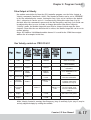
Example for Bit-accessed Data in PLC CPUs . . . . . . . . . . . . . . . . . . . . . . . . . . . . .4–9
Addressing High and Low Byte of Word Parameters . . . . . . . . . . . . . . . . . . . . . . .4–9
Addressing High and Low Word of DWord Parameters . . . . . . . . . . . . . . . . . . . . .4–9
Pulse Output Commands . . . . . . . . . . . . . . . . . . . . . . . . . . . . . . . . . . . . . . . . . .4–10
Status Registers (status bit from CTRIO) . . . . . . . . . . . . . . . . . . . . . . . . . . . . . . .4–12
Pulse Output Profiles . . . . . . . . . . . . . . . . . . . . . . . . . . . .
Control Registers (control DWords, Words, and bits . . . . .
Running a Trapezoid or S-Curve Profile on CTRIO Y0 & Y1
Trapezoid or S-Curve . . . . . . . . . . . . . . . . . . . . . . . . . . .
Dynamic Positioning . . . . . . . . . . . . . . . . . . . . . . . . . . .
Dynamic Positioning using the CTRIO Y0 and Y1 . . . . . . .
Pulse Output at Velocity . . . . . . . . . . . . . . . . . . . . . . . . .
Run Velocity control on CTRIO Y0 &Y1 . . . . . . . . . . . . . .
Pulse Output to Input Limit . . . . . . . . . . . . . . . . . . . . . .
Run Velocity on CTRIO Y0 & Y1 until Discrete Input Limit .
Pulse Output to Position . . . . . . . . . . . . . . . . . . . . . . . . .
Run Velocity on CTRIO until Function Input Value . . . . . . .
.
.
.
.
.
.
.
.
.
.
.
.
.
.
.
.
.
.
.
.
.
.
.
.
.
.
.
.
.
.
.
.
.
.
.
.
.
.
.
.
.
.
.
.
.
.
.
.
.
.
.
.
.
.
.
.
.
.
.
.
.
.
.
.
.
.
.
.
.
.
.
.
.
.
.
.
.
.
.
.
.
.
.
.
.
.
.
.
.
.
.
.
.
.
.
.
.
.
.
.
.
.
.
.
.
.
.
.
.
.
.
.
.
.
.
.
.
.
.
.
.
.
.
.
.
.
.
.
.
.
.
.
.
.
.
.
.
.
.
.
.
.
.
.
.
.
.
.
.
.
.
.
.
.
.
.
.
.
.
.
.
.
.
.
.
.
.
.
.
.
.
.
.
.
.
.
.
.
.
.
.
.
.
.
.
.
.
.
.
.
.
.
CTRIO High Speed Counter Module
.4–12
.4–13
.4–14
.4–14
.4–15
.4–16
.4–17
.4–17
.4–18
.4–18
.4–19
.4–19
iii
THIS PAGE INTENTIONALLY LEFT BLANK.
INTRODUCTION TO THE
CTRIO MODULE
CHAPTER
1
In This Chapter...
General Information about the CTRIO Module
. . . . . . . . . . . . . . .1–2
Specifications . . . . . . . . . . . . . . . . . . . . . . . . . . . . . . . . . . . . . . . .1–3
Introduction
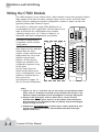
General Information about the CTRIO Module
The Counter I/O (CTRIO) module is designed
to accept high-speed pulse-type input signals
and provide discrete or pulse outputs for
monitoring, alarm, or control functions. The
CTRIO module offers great flexibility for
applications which call for precise counting
or timing, based on input events.
The CTRIO module has its own
microprocessor and operates asynchronously
with respect to the CPU. The response time of
on-board outputs is based on the module’s
scan time, not the CPU’s scan time.
n + 20.
status
D
CTRIO Workbench
All scaling and configuration is done
via a software utility, eliminating the
need for ladder programming to set up
the module. The software utility is
called CTRIO Workbench. The use of
CTRIO Workbench is explained in
Chapter 3.
Supported CPUs
You can use the CTRIO module with
conventional CPUs (D2-240 or D2-250),
our Windows-based WinPLC CPU
module, or PC-based control strategies
using the H2-EBC interface module.
The CTRIO module plugs into any I/O slot of any DirectLogic 205 base except slot 0 (slot
0 is available for the CTRIO module when using the WinPLC CPU). Slot 0 is the I/O slot
adjacent to the CPU. Multiple CTRIO modules can reside in the same base provided that
the power supply is adequate. CTRIO modules may be placed in secondary local bases
connected via ERM-to-EBC.
The CTRIO module is designed to work with incremental encoders or other field devices
that generate pulses or edges.
Typical Counter Applications:
• cut to length
• piece counting
• positioning (e.g. flying punch)
• PLS - programmable limit switch replacement (e.g. gluing application)
• stepper motor drive control
• valve control
• rate monitoring for speed and/or flow
1–2
Counter I/O User Manual
Introduction
Specifications
General
Module Type
Intelligent
Modules Per Base
Limited only by power consumption
I/O Points Used
None, I/O map directly in PLC V-memory or PC
control access
Field Wiring Connector
Standard removable terminal block
Internal Power Consumption
400mA Max at +5V from 205 Base Power Supply
Maximum of 6 Watts (All I/O in ON State at Max
Voltage/Current)
Operating Environment
32°F to 140°F (0°C to 60°C),
Humidity (non-condensing) 5% to 95%
Manufacturer
Host Automation Products, LLC
Isolation
2500V I/O to Logic, 1000V among Input
Channels and All Outputs
Inputs
Primary Inputs
4 pts sink/source 100K Hz Max
Secondary Inputs
4 pts, high speed, for Reset, Inhibit, or Capture
Minimum Pulse Width
5 µsec
Input Voltage Range
9-30VDC
Maximum Voltage
30VDC
Input Voltage Protection
Zener Clamped at 33VDC
Rated Input Current
8mA typical 12mA maximum
Minimum ON Voltage
9.0VDC
Maximum OFF Voltage
2.0VDC
Minimum ON Current
5.0mA (9VDC required to guarantee ON state)
Maximum OFF Current
2.0mA
OFF to ON Response
Less than 3 µsec
ON to OFF Response
Less than 3 µsec
Counter I/O User Manual
1–3
Introduction
Specifications (cont’d)
CTRIO Output Specifications
Outputs
4 pts, independently isolated, current sourcing or
sinking (open collector)
Pulse output control
2 channels, 20Hz - 25kHz (per channel), pulse
and direction or cw/ccw pulses (50kHz if using
only 1 channel)
Voltage range
5VDC - 36VDC
Maximum voltage
36VDC
Output clamp voltage
60VDC
Maximum load current
1.0A
Maximum load voltage
36VDC
Maximum leakage current
100µA
Inrush current
5A for 20ms
OFF to ON response
less than 3µsec
ON to OFF response
less than 3µsec
ON state V drop
울 0.3V
External power supply
for loop power only, not required for internal
module function*
Overcurrent protection
15A max
Thermal shutdown
Tjunction = 150°C
Overtemperature reset
Tjunction = 130°C
Target position range
- 2.1 billion to + 2.1 billion (31 bits + sign bit)
Duty cycle range
1% to 99% in 1% increments (default = 50%)
Configurable Presets
a) single
b)mulitple
a) each output can be assigned one preset, or
b) each output can be assigned one table of
presets, one table can contain max. 128 presets,
max. predefined tables = 255
* User supplied power source required for stepper drive configurations
1–4
Counter I/O User Manual
Introduction
Specifications (cont’d)
Resources
Counter/Timer
Four (2 per 4 input channel group)
Resource Options
1X, 2X, or 4X Quadrature, Up or Down Counter,
Edge Timer, Dual Edge Timer, Input Pulse Catch
Timer Resolution
1 µsec
Counter Range
앧2.1 billion (32 bit + sign bit)
LED Descriptions
OK
Module OK
0
Out 0
ER
User Program Error
1
Out 1
1A
Ch 1 A Status / Pulses
2
Out 2
Ch 2 A Status / Pulses
3
Out 3
(C1 on older modules)
2A
(CTR2 on older modules)
LED Definitions
OK
ER
ON
OFF
All is well - RUN Mode
ON
ON
205 Base Power Fault
Blinking
Blinking
Blinking
OFF
OFF
Blinking
OFF
ON
Module Error Due to Watchdog Timeout
OFF
OFF
No Power to Module
1 A or 2A
(C1 or CTR2 on older modules)
Description
Boot Mode - Used for Field OS Upgrades
Program Mode
Module Self-diagnostic Failure
Based on Configuration of Input A
Blinking 7 times per second
A is Configured as Counter and is Changing
Following State of Input
A is not Configured as Counter
Output LEDs 0 - 3 Follow Actual Output State
Counter I/O User Manual
1–5
THIS PAGE INTENTIONALLY LEFT BLANK.
INSTALLATION AND
FIELD WIRING
CHAPTER
2
In This Chapter...
How to Install the CTRIO Module . . . . . . . . . . . . . . . . . . . . . . . . .2–2
Jumpers
. . . . . . . . . . . . . . . . . . . . . . . . . . . . . . . . . . . . . . . . . . .2–3
Wiring the CTRIO Module . . . . . . . . . . . . . . . . . . . . . . . . . . . . . .2–4
Solid State Input Device Wiring . . . . . . . . . . . . . . . . . . . . . . . . . . .2–5
Output Schematic . . . . . . . . . . . . . . . . . . . . . . . . . . . . . . . . . . . .2–6
Quadrature Encoder Wiring Example . . . . . . . . . . . . . . . . . . . . . . .2–7
Stepper Drive Wiring Example . . . . . . . . . . . . . . . . . . . . . . . . . . . .2–7
TTL Quadrature Encoder Field Wiring . . . . . . . . . . . . . . . . . . . . . .2–8
TTL Input Wiring . . . . . . . . . . . . . . . . . . . . . . . . . . . . . . . . . . . . .2–9
Installation and Field Wiring
How to Install the CTRIO Module
The CTRIO module installs into any DL205 base, and it is compatible with several
DL205 CPU-slot devices. Consideration must be given to the firmware versions of the
CPU-slot devices to assure their compatibility (see chart below).
DirectSOFT32 version 3.0C, Build 71 (or later) is required for use with the CTRIO
module if the D2-240 or D2-250 CPUs are to be used.
The first time you power-up the CTRIO module, you should see the OK LED blinking. The
blinking LED indicates that the module is in program mode.
CPU and CTRIO Compatibility Chart
CPU-slot Device
Firmware
Slot Restrictions
Max. per Base
D2-240
v. 3.22 or later
any I/O slot except 0
6 CTRIO modules in 9-slot
bases, 3 modules in
smaller bases*
D2-250
v. 1.56 or later
any I/O slot except 0
6 CTRIO modules in 9-slot
bases, 3 modules in
smaller bases
any I/O slot
6 CTRIO modules in 9-slot
bases, 3 modules in
smaller bases
any I/O slot except 0
6 CTRIO modules in 9-slot
bases, 3 modules in
smaller bases
H2-WinPLC
H2-EBC
v. 2.1.357 or
later
* for applications requiring multiple CTRIO modules, DirectLOGIC CPUs, and dynamic
access (in ladder logic) to CTRIO data, we recommend using the D2-250 CPU.
D2-240 or
D2-250 or
H2-EBC or
WinPLC
2–2
Counter I/O User Manual
Slot 0
Slot 1
Slot 2
Slot 3
Slot 4
through
Slot 7
Installation and Field Wiring
Jumpers
Jumpers are provided to connect input commons or outputs/output commons. Use of
these jumpers is not necessary to set up the CTRIO module. The jumpers are provided
solely for convenience in wiring.
1M
2M
Y0
Y1
Y0
Y2
Y0
Y3
C0
C1
C0
C2
C0
C3
Jumper Settings
1M to 2M
Y0 to Y1, Y2, Y3
C0 to C1, C2, C3
Share supply voltage between Ch 1 & Ch2
Share commons between high or low side of
outputs when isolation is not required
Counter I/O User Manual
2–3
Installation and Field Wiring
Wiring the CTRIO Module
The CTRIO module is a two channel device. Each channel accepts four optically isolated
input signals which share the same common. Input circuits can be wired with either
polarity without changing the module configuration. Channel 1 inputs can have the
opposite polarity from channel 2 inputs.
The module is configured, using CTRIO Workbench, to
accommodate the user’s application. The function of each
input is defined in the configuration of the module
(counting, timing, reset, etc.). Refer to Chapter 3, to
determine what input configurations are possible.
Field device wiring must be
compatible with the module
configuration.
Channel 1
Channel 2
1A
2A
2A
2B
1C
2C
2C
1D
2D
2D
1M
-
2M
+
-
+
See the notes below for
further details about power
source considerations, circuit
polarities, and field devices.
Also, refer to the
specifications on pages 1-2
and 1-3 for more information.
IN 9-30VDC 5-12mA
OUT 5-36VDC
1.0A max
per point
1B
2B
+
NC
-
Each output circuit is optically
isolated from the other
outputs. Output commons are
independent but can be tied
together using internal
jumpers. All four discrete
outputs are available to be
energized in response to any
of the inputs.
CTR
+24VDC
IN
OUT PUTS
0
OK
1
ER
C1
2
3
C TR 2
H2--CTRI O
-
+
+
C0
+
Y2
L
-
-
+
L
+
C3
Y3
Y0
L
-
C2
Y2
C2
-
2M
C3
1A
1B
1C
1D
1M
NC
C0
Y0
C1
Y1
C1
+
Y3
Y1
L
Notes:
1. Inputs (1A, 1B, 1C, 1D and 2A, 2B, 2C, 2D) require user-provided 9-30VDC
power sources. Terminals 1M and 2M are the commons for Channel 1 and
Channel 2 inputs. Maximum current consumption is 12mA per input point.
2. Polarity of the input power sources (shown above) can be reversed.
Consideration must be given, however, to the polarity of the field device.
Many field devices are designed for only one polarity and can be damaged
if power wiring is reversed.
3. Outputs have one polarity only (as shown above) and are powered by userprovided 5-36VDC power sources. The maximum allowable current per
output circuit is 1A.
2–4
Counter I/O User Manual
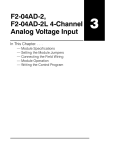
Installation and Field Wiring
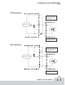
NPN Field Device
This drawing illustrates wiring that is
typical for Channel 1 terminals 1A, 1B,
1C, and 1D. The same circuitry is also
present at the corresponding
Channel 2 terminals.
1A
Sensing Circuit
24VDC
- +
1M
The same circuitry is present at the
corresponding Channel 2 terminal.
24VDC
PNP Field Device
Sensing Circuit
This drawing illustrates wiring that is
typical for Channel 1 terminals 1A, 1B,
1C, and 1D. The same circuitry is also
present at the corresponding
Channel 2 terminals.
+
-
1A
1M
The same circuitry is present at the
corresponding Channel 2 terminal.
Counter I/O User Manual
2–5
Installation and Field Wiring
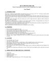
Output Schematic
The CTRIO outputs are individually isolated DC switches that can be used to break the
high or the low side of a DC load.
Cn (where n=0, 1, 2, 3)
CTRIO
Output
+5 to 36VDC
Yn
+
Load
-
+
Load
+5 to 36VDC
Cn (where n=0, 1, 2, 3)
CTRIO
Output
Yn
2–6
Counter I/O User Manual
Installation and Field Wiring
Quadrature Encoder Wiring Example
1A
2A
A
1B
A
B
2B
B
1C
Z
2C
Power
2D
Z
1M
Power
9-30VDC
+
-
Gnd
9-30VDC
1D
+
-
Gnd
2M
NC
C2
C0
Y2
Y0
C3
C1
Y3
Y1
Stepper Drive Wiring Example
1A
2A
1B
2B
1C
2C
1D
2D
1M
2M
NC
Step Amplifier
5-36VDC
OPTO Power
Pulse
(or CW)
Direction (or CCW)
Step Amplifier
C2
C0
+ Y2
Y0
5-36VDC
- +
OPTO Power
Pulse
(or CW)
C3
C1
Direction (or CCW)
Y3
Y1
Counter I/O User Manual
2–7
Installation and Field Wiring
TTL Quadrature Encoder Field Wiring
1A
2A
C
1B
2B
HFE > 100
1C
2C
10K
B
E
1D
A
0.1W
10%
B
Z
2D
1M
C
2M
NC
HFE > 100
C2
10K
B
0.1W
10%
C0
E
Y2
Y0
C3
C
Y3
Y1
+
2–8
9 - 30VDC
HFE > 100
Counter I/O User Manual
E
B
10K
0.1W
10%
Gnd
+
-
5VDC
Power
C1
Installation and Field Wiring
TTL Input Wiring
NPN
General Purpose Transistor
1A
2A
TTL Device
C
1B
2B
B
HFE > 100
1C
2C
0.1W
10%
E
1D
10K
2D
1M
2M
NC
C2
C0
TTL Device
C
Y2
Y0
B
HFE > 100
0.1W
10%
C3
C1
10K
E
Y3
+
9 - 30VDC
Y1
TTL Device
C
B
10K
HFE > 100
0.1W
10%
E
TTL Device
C
B
HFE > 100
E
10K
0.1W
10%
Counter I/O User Manual
2–9
THIS PAGE INTENTIONALLY LEFT BLANK.
CHAPTER
CTRIO WORKBENCH
3
1
In This Chapter...
What is CTRIO Workbench? . . . . . . . . . . . . . . . . . . . . . . . . . . . . .3–2
Getting Started with CTRIO Workbench . . . . . . . . . . . . . . . . . . . .3–2
Input Function Selections . . . . . . . . . . . . . . . . . . . . . . . . . . . . . . .3–7
Introduction to the Scaling Wizard . . . . . . . . . . . . . . . . . . . . . . .3–16
Using the Monitor I/O Dialog
. . . . . . . . . . . . . . . . . . . . . . . . . .3–20
Discrete Outputs . . . . . . . . . . . . . . . . . . . . . . . . . . . . . . . . . . . .3–21
Creating and Using the Output Preset Tables
. . . . . . . . . . . . . . .3–22
I/O Map Dialog . . . . . . . . . . . . . . . . . . . . . . . . . . . . . . . . . . . . .3–23
Chapter 3: Configuring the CTRIO with Workbench
What is CTRIO Workbench?
CTRIO Workbench is the software utility you will use to configure the CTRIO module
and to scale signals to desired engineering units. Workbench also allows you to perform
various other functions, such as switching between the CTRIO’s Program mode and Run
mode, monitoring I/O status and functions, and diagnostic control of module functions.
The CTRIO Workbench utility ships with the CTRIO User Manual. You can also
download the latest version free at the Host Engineering Web site: www.hosteng.com.
Installing CTRIO Workbench
The CTRIO Workbench utility installs directly from its executable file. Double click on
the SetupCTR.exe icon. The install shield will step you through the installation process.
Two versions of CTRIO Workbench are loaded on your PC during the installation. One is
for DirectSOFT32 users. It runs from within DirectSOFT32. CTRIO Workbench requires
DirectSoft32, Rel. 3.0C, Build 71 (or later).
The other version is for H2-WPLC and H2-EBC users, and it may or may not run from
within the control software furnished with the WinPLC module. For further information,
see your WinPLC’s software documentation.
Getting Started with CTRIO Workbench
To run CTRIO Workbench, an H2-CTRIO module must be
installed in the base, and the base must be powered up.
You will need to connect to a port on the DirectLOGIC
CPU, D2-DCM, H2-ECOM, H2-EBC, or H2-WPLC. Your PC
communicates with the CTRIO module through the CPUslot device port or through a port on a DCM or ECOM
module.
Several paths are available to start CTRIO Workbench.
DirectSOFT32 users will find CTRIO Workbench under
PLC (menu)/Tools/CTRIO Workbench.
DirectSOFT32 users will also find
access to CTRIO Workbench in the
DirectSOFT32 Launch Window. Double
click the Workbench icon as you would
do to open a project.
All users will find CTRIO Workbench at
Start/Programs/AutomationDirect
Tools/CTRIO Workbench.
3–2
Counter I/O User Manual
Chapter 3: Configuring the CTRIO with Workbench
Linking to CTRIO Module in DirectSOFT32
If you are linked to your CPU through
DirectSOFT32, CTRIO Workbench will
start via the existing link. If you are
“disconnected” from your PLC and start
CTRIO Workbench, you will be prompted
to establish a link to your CTRIO module.
Successful Connection
Once you are connected to your PLC (or
PLC network) and you select the desired
CPU (Link), you will enter the main
window of CTRIO Workbench. Here, you
select the CTRIO module you wish to configure by clicking on its slot number in the
“Installed Modules” box. If the steps mentioned above are all accomplished
successfully, you will be able to enter Workbench’s configuration and monitoring
dialogs, and you will be able to toggle the CTRIO module between Program Mode and
Run Mode.
Counter I/O User Manual
3–3
Chapter 3: Configuring the CTRIO with Workbench
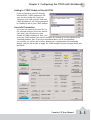
Choose “Program Mode” to Configure the CTRIO Module
On the CTRIO Workbench main window,
a single button toggles between Run
Mode and Program Mode. The Module
Mode indicator will tell you which mode
your module is in. You can configure the
module “offline” in either Run Mode or
Program Mode, but to save your
configuration to the module, you must
click “Write Module” which is only active
in Program Mode.
Clicking on the Config I/O button, causes
the Configure I/O window to appear. From the Configure I/O
window, you can select the primary input functions your
application requires and assign those functions to
appropriate terminals.
You can also select subordinate functions on the Configure
IO dialog. Primary and subordinate functions are explained
in more detail under the heading “Supported Functions.”
After the configuration is created in CTRIO Workbench, it must be “written” to the
CTRIO module. This is accomplished by returning to the main CTRIO Workbench
window and clicking on “Write Module.”
Entering program mode takes the CTRIO module offline. Input pulses are not read or
processed in Program mode, and all outputs are disabled. DirectLOGIC CPUs will hold
last value in V-memory while the CTRIO is in Program Mode.
Choose “Run Mode” to Start Processing Pulses with the CTRIO
Selecting Run Mode causes the CTRIO module to begin processing pulses based on the
configuration you created.
In Run mode the CTRIO Workbench utility also allows you to monitor and verify the
proper operation of inputs and outputs. You can see the count change, reset, etc. The
Monitor feature is particularly useful during debugging and commissioning of a new
system. This feature allows you to verify that wiring and configuration were performed
correctly.
If you are using a DirectLOGIC CPU, the CTRIO mode follows the CPU mode. If the CPU
is placed in Run Mode, the CTRIO module will also enter Run Mode. If the CPU is placed
in STOP or PROGRAM Mode, the CTRIO will enter Program Mode. The CTRIO also
responds to mode changes made in Workbench and can be placed in Run Mode while
the CPU is in Stop or Program Mode. The CTRIO module responds to the most recent
change whether performed in Workbench or from the CPU.
The CTRIO module will not enter Run Mode if it does not have a valid configuration
stored.
3–4
Counter I/O User Manual
Chapter 3: Configuring the CTRIO with Workbench
Using the Configure IO Dialog
The Configure IO dialog is the location where input and output functions are assigned
to the module. The choice of input and output functions determines which options are
available.
The input function boxes prompt you with selections for supported functions. The
Workbench software disallows any unsupported configurations.
From the main CTRIO Workbench window, click on the “Go to PROGRAM Mode” button.
Then, click on the “Config I/O”
button to arrive at the dialog below.
Notice that the window has a tab for
each Channel. Channel 1 and
Channel 2 offer the same
configuration options.
A maximum of one quadrature input
or two single-ended encoder inputs
is possible for each channel.
The input options are listed by
function. Four boxes labeled A, B, C,
and D correspond to the input
terminals on the face of the module.
Select the desired input function by
clicking on the input type and then
clicking OK.
For example, you might click on
“Counter” in the “A” box, then OK to
return to the main Workbench
window. Once you arrive back at the main window, you must click “Write Module” to
save your selection to the module. The module will need to be in Program Mode to
perform the Write Module operation. If you do not perform the Write Module operation
(or a Write File operation) your configuration will be lost upon quitting Workbench. This
applies to all changes to the module configuration.
In the lower left corner of the main Workbench dialog, is the Config Status indicator. If
the current configuration is different from the CTRIO and different from any saved files,
the indicator will display the word “Changed.” If the current configuration has been
written to the module or a file, the message will read “Same as Module,” “Same as
File,” or “Same as Both.”
Field devices and field wiring must be consistent with the configuration chosen.
The Output functions are listed as 0, 1, 2, and 3. These numbers correspond to the
markings beside the module’s output terminals. Again, only supported functions are
accessible. It is not possible to create an “illegal” configuration.
Counter I/O User Manual
3–5
Chapter 3: Configuring the CTRIO with Workbench
Supported Functions
Reset, Inhibit, and Capture. If desired, two subordinate functions can be selected for the
first Counter on each channel, Reset and Inhibit or Reset and Capture.
Capture and Inhibit use the same terminal, so you cannot use both of those subordinate
functions. You can also access the Scaling Wizard, for counting and timing applications
and other configuration features.
The CTRIO module supports five primary input functions: Counter, Quad Counter, Pulse
Catch, Edge Timer, and Dual Edge Timer. Each of the primary functions uses one or two
terminals for making connections to field devices (plus a common).
Three secondary input functions are also supported. These functions, Reset, Capture,
and Inhibit, each modify the primary input functions in some way. More information is
available about each of the primary and secondary functions later in this chapter.
3–6
Counter I/O User Manual
Chapter 3: Configuring the CTRIO with Workbench
Input Function Selections
To make function selections (counter, timer, etc.), navigate to
the Configuration IO dialog. From the main Workbench
window, click the “Config IO” button to open the Config IO
dialog.
Counter Function
The CTRIO module supports up or down counting using single-ended encoders (or other
single-ended pulse sources) as inputs. Encoders, proximity sensors, etc., can be
connected to input A and/or input B on either channel or both channels. The C and D
inputs are available to modify the A and B inputs. The C and D inputs can be used for
Reset, Inhibit, or Capture. These
functions are more fully explained later
in this chapter.
To insure proper operation, the field
device wiring and the configuration
must be compatible. For wiring
information see Chapter 2.
A
To select the Counter function, first
open CTRIO Workbench. On the main
dialog, click the button labeled “Config
IO.” This causes the Input Settings
dialog to open.
The module’s four input terminals are
represented by the A, B, C, and D
boxes on the left side of this dialog. If
you are wiring your counter input to
terminal 1A, you will want to select the
Channel 1 tab near the top of this
window and click “Counter” in box A.
At this point, you have four decisions to
make regarding your input at 1A.
1. Select count up or count down. A
button, in the Function 1 box, toggles
between Up and Down counting.
Click the button labeled “Up” (or
“Down”) to see the change to the
opposite count direction.
2. Each input pulse is counted, but
you are free to designate whether you
want the count to register on the
rising edge of the pulse, the falling
edge, or both. The button with the
graphical representation of a pulse
toggles between these choices.
Counter I/O User Manual
3–7
Chapter 3: Configuring the CTRIO with Workbench
3. The Reset value is assigned by clicking and typing a value in the data input field.
This value is for hardwired resets. When the hardwired reset is activated, the count
value returns to the reset value.
4. The last remaining decision to be made is about scaling. Clicking the button with
the ruler symbol starts the Scaling Wizard. We discuss the scaling wizard later in this
chapter. The Scaling Wizard is intelligent in that it offers scaling options that are
appropriate for your input selections.
3–8
Counter I/O User Manual
Chapter 3: Configuring the CTRIO with Workbench
Quad Counter
The CTRIO module supports
quadrature counting using quadrature
encoders as inputs. Connect your
encoder to input A and input B on
either channel. A second quadrature
endcoder can be connected to the
other channel. The C and D inputs are
available to control the quadrature
input counting. The C and D inputs can
be used for Reset, Inhibit, or Capture.
These functions are more fully
explained later in this chapter.
A
B
To insure proper operation, the field
device wiring and the configuration
must be compatible. For wiring
information see Chapter 2.
To select the Quad Counter function,
first open CTRIO Workbench. On the
main dialog, click the button labeled
“Config I/O.” This causes the Configure
IO dialog to open.
Notice that the module’s four input
terminals are represented by the A, B, C,
and D boxes on the left side of this
dialog. If you are wiring your quadrature
counter inputs to terminal 1A and 1B,
you will need to select the Channel 1 tab
near the top of this window and click
“Quad Counter” in box A. Notice that
input B is now slaved to input A.
At this point, you have three decisions to
make regarding your quadrature input.
1. A multiplier can be applied to the quadrature input to increase its resolution.
Select “1x”, “2x”, or “4x.” [1X = pulses processed on leading edge of input A, 2X =
pulses are processed on both edges of input A, 4X = pulses processed on both edges
of input A and both edges of input B.]
2. The “Reset Value” is assigned by clicking in the data input field and typing in a
value. When the count is reset, using any of the reset methods, the count value
returns to the Reset Value. The reset options are described in more detail later in this
chapter.
3. The last remaining decision to be made is about scaling. Clicking the button with
the ruler symbol starts the Scaling Wizard. The Scaling Wizard is intelligent in that it
offers only those scaling options that are appropriate for your input selections. We
discuss the scaling wizard in greater detail later in this chapter.
Counter I/O User Manual
3–9
Chapter 3: Configuring the CTRIO with Workbench
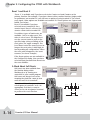
Pulse Catch
The CTRIO “Pulse Catch” function allows a very short duration pulse to be qualified and
lengthened to a time period long enough to guarantee that it is seen by the CPU. CPU
scans necessarily vary with the length and complexity of the user’s program. A scan
frequency of several milliseconds, or more, is common. A pulse that lasts less than one
millisecond, is typically hard to catch during the CPU scan.
The CTRIO module’s Pulse Catch function sees the fast incoming signal and holds its
status in a status bit until the CPU can see it. A discrete output can also be tied to the
Pulse Out.
To insure proper operation, the field
device wiring and the configuration
must be compatible. For wiring
information see Chapter 2.
To select the Pulse Catch function, first
open CTRIO Workbench. On the main
dialog, click the button labeled “Config
I/O.” This causes the Input Settings
dialog to open.
Notice that the module’s four input
terminals are represented by the A, B,
C, and D boxes on the left side of this
dialog. If you are wiring your input to
terminal 1C, you will need to select the
Channel 1 tab near the top of this
window and click Pulse Catch in box C.
Three selections must be made in conjunction with the Pulse Catch option.
1. First, a decision must be made whether to look for the rising edge of the pulse or
the falling edge of the pulse. This
is a critical decision. Careful
attention should be paid to the
type of output the field device
generates. If the signal voltage is
normally low, but a short duration
pulse sends the signal to the ON
n + 20.8
state, you will want to trigger off
status bit
the rising edge, and vice versa.
2. The second decision you will
need to make is the minimum
pulse width you want to capture.
Transients below this width will
not be recorded. Set this value by
typing the desired value in the
“Minimum Width In” field.
D
3. The final decision to be made is the length of pulse the CTRIO module should
send in response to the input pulse. Make this setting by typing in the desired value
in the “Pulse Out Width” field.
3–10
Counter I/O User Manual
Chapter 3: Configuring the CTRIO with Workbench
Edge Timer
The Edge Timer measures the time
from the rising edge of one pulse to
the rising edge of the next pulse, or the
falling edge of one pulse to the falling
edge of the same pulse, or the falling
edge of one pulse to the falling edge of
the next pulse. Encoders, proximity
sensors, etc., can be connected to
input C and/or input D on either
channel or both channels.
A
To insure proper operation, the field
device wiring and the configuration
must be compatible. For wiring
information see Chapter 2.
To select the Edge Timer function, first
open CTRIO Workbench. On the main dialog, click the button labeled “Config I/O.” This
causes the Input Settings dialog to open.
Notice that the module’s four input
terminals are represented by the A, B,
C, and D boxes on the left side of this
dialog. If you are wiring your input to
terminal 1C, you will need to select the
Channel 1 tab near the top of this
window and click Counter in box C.
At this point, you have three decisions
to make regarding your input at 1A.
1. First, designate the pulse edges
you want to measure between. There
are four choices. You can measure
the time from the leading edge of the
upward pulse to the leading edge of
the next upward pulse, or from the
trailing edge of an upward pulse to
the trailing edge of the next upward
pulse, or from the leading edge of an
upward pulse to the trailing edge of the same pulse, or, finally, from the leading edge
of a downward pulse to the trailing edge of the same downward pulse.
The last option could be restated as timing from the trailing edge of an upward pulse
to the rising edge of the next upward pulse.
2. The “Free Run” option is assigned by clicking in the appropriate box. If your
application calls for velocity measurements to be taken at the commencement of
some event, do not use Free Run. If your application calls for velocity measurement
on a continuous (moving average) basis, you should use Free Run.
Counter I/O User Manual
3–11
Chapter 3: Configuring the CTRIO with Workbench
3. The last remaining decision to be made is about scaling. Clicking the button with
the tape measure symbol starts the Scaling Wizard. We discuss the scaling wizard
later in this chapter. The Scaling Wizard is intelligent in that it offers scaling options
that are appropriate for your input selections.
Dual Edge Timer
The Dual Edge Timer is designed to measure from a pulse edge on one incoming signal
to a pulse edge on another incoming signal. The user selects whether to measure
between rising edges, falling edges, etc. The choices are summarized in the tables
below.
Dual Edge Timer at Function 1
Dual Edge Timer at Function 2
Rising edge of C to rising edge of D
Rising edge of D to rising edge of C
Rising edge of C to falling edge of D
Rising edge of D to falling edge of C
Falling edge of C to rising edge of D
Falling edge of D to rising edge of C
Falling edge of C to falling edge of D
Falling edge of D to falling edge of C
To insure proper operation, the field device wiring and the configuration must be
compatible. For wiring information see Chapter 2.
To select the Dual Edge Timer function, first open CTRIO Workbench. On the main
dialog, click the button labeled “Config I/O.” This causes the Input Settings dialog to
open.
Notice that the module’s four input terminals are
represented by the A, B, C, and D boxes on the
left side of this dialog. If you are wiring your
inputs to terminals 1C and 1D, you will need to
select the Channel 1 tab near the top of this
window and click Dual Edge Timer in box C or D.
3–12
Counter I/O User Manual
Chapter 3: Configuring the CTRIO with Workbench
Dual Edge Timer (cont’d)
At this point, you have three
decisions to make regarding your
input at 1C or 1D.
1. First, designate the pulse
edges you want to measure
between.
C (or D)
D (or C)
2. The “Free Run” option is
assigned by clicking in the
appropriate box. If your
application calls for velocity
measurements to be taken at
the commencement of some
event, do not use Free Run. If
your application calls for
velocity measurement on a continuous basis, you should use Free Run.
3. The last remaining decision to be made is about scaling. Clicking the button with
the tape measure symbol starts the Scaling Wizard. We discuss the scaling wizard
later in this chapter. The Scaling Wizard is intelligent in that it offers scaling options
that are appropriate for your input selections.
Counter I/O User Manual
3–13
Chapter 3: Configuring the CTRIO with Workbench
Reset 1 and Reset 2
“Reset 1” is available only if you have selected a Counter or Quad Counter as the
primary function. For example, if you have chosen either counter function (single-ended
or quadrature) on terminal 1A, you will have an option of using terminal 1C for a hard
reset signal. Other options are available on terminal 1D. Those options are Capture and
Inhibit (see below).
Reset 2 is available if you have
selected to use terminal 1B for a
counter input. Reset 2 will reset the
counter connected to terminal 1B.
Two distinct types of hard resets are
available. One is an edge reset. The
other is a level reset. The Edge Reset
sets the current count to zero on the
specified edge (rising or falling) of the
reset pulse (see upper exampel). The
Level Reset resets the count to zero (as
long as the reset pulse is held high (or
low depending on configuration). When
the reset pulse disappears, the count
resumes (see lower example).
n-1
n
1
2
A
C
Edge Reset
If the Reset options are not available in
the Configure IO dialog, then you have
selected input functions that do not use
the reset modifier.
A Word About Soft Resets
Soft resets are also available from
the Monitor dialog within
Workbench or by turning on a
control bit in your control program.
Soft resets are always level resets,
meaning they hold the count at zero
until the reset bit is turned off.
Reset 1 and Reset 2 represent hardwired inputs to terminal C or D. An
appropriate field device must be
connected to the designated terminal
to perform the reset function.
n-1
n
Level Reset
3–14
Counter I/O User Manual
1
A
C
Chapter 3: Configuring the CTRIO with Workbench
Capture 1
“Capture 1” is available only if you have selected a Counter or Quad Counter as the
primary function. For example, if you
have chosen either counter function on
terminal 1A, you will have an option of
using terminal 1D for a capture signal.
Capture 1 “snapshots” the current
count into the 2nd DWord register
(Parameter 2). The Capture feature is
available with a single-ended Counter
on input A or a Quad Counter on inputs
A and B.
n-1
n
n+2
A
D
Capture
Capture 1 represents a hard-wired
input to terminal D. An appropriate
field device must be connected to the
designated terminal to perform the
capture function.
The Capture feature must be enabled in your control program or on the Monitor dialog
in CTRIO Workbench.
Inhibit 1
“Inhibit 1” is available only if you have
selected a Counter or Quad Counter as
the primary function. For example, if
you have chosen either counter function
on terminal 1A, you will have an option
of using terminal 1D for an inhibit
signal.
n-1
n
The “Inhibit 1” signal prevents the
receipt of pulses into the Counter or
Quad Counter input terminals. The
Inhibit feature is available with the “A”
Counter or Quad Counter on each
channel.
n+1
Inhibit
A
D
Inhibit 1 represents a hard-wired input
to terminal D. An appropriate field device must be connected to the designated
terminal to perform the inhibit function.
Counter I/O User Manual
3–15
Chapter 3: Configuring the CTRIO with Workbench
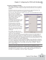
Introduction to the Scaling Wizard
Scaling raw signals to engineering units is
accomplished using the Scaling Wizard. Start
the Scaling Wizard by clicking the ruler
button on the Configure IO dialog. This
button appears only after you select one of
the Counter or Timer functions.
The Scaling Wizard options are different for
the Counter functions as compared with the
Timer functions. “Position” and “Rate”
scaling are available when you select a
Counter function. “Interval” scaling is
available when you select a Timing function.
We will step through the dialogs used for each scaling type. Substitute appropriate
values to set up scaling for your application.
Scaling Wizard Examples for Counter Functions
On the counter Scaling
Wizard, you can select None,
Position, or Rate. No scaling
is accomplished if the None
button is selected. Position
scaling is appropriate for
measuring distance,
position, or size. Rate scaling
is appropriate for velocity,
RPM, flow, or similar rate
based measurements. You
may want to read the Notes
and other information before
leaving this window.
3–16
Counter I/O User Manual
Chapter 3: Configuring the CTRIO with Workbench
Position Scaling (Counter)
To select Position Scaling, click the radio button beside the word
Position. Now, click Next to move to the Output Settings dialog.
On the Output Settings dialog, you will
notice the field for engineering units. Enter
an appropriate value for Position Scaling, for
example yards, feet, meters, cubic inches,
etc. Seven data types are available including
BCD (to make values more easily used by
DirectLOGIC PLCs).
Click Next, to open the Position Settings dialog.
It is here that you enter the span of raw counts
that equates to a span of engineering units.
This window contains a calculator to double
check the meaning of your Position Settings.
Enter a value into the Raw Value field to see the
equivalent value in engineering units.
Counter I/O User Manual
3–17
Chapter 3: Configuring the CTRIO with Workbench
Rate Scaling (Counter)
To select Rate Scaling, click the radio button beside the word Rate.
Now, click Next to move to the Output Settings dialog.
On the Output Settings dialog, you will notice
the field for engineering units. Enter an
appropriate value for Rate Scaling, for
example RPM, fps, flow, etc. Seven data types
are available including BCD (to make values
more easily used by DirectLOGIC PLCs).
Click Next, to open the Rate Settings
dialog. It is here that you enter the counts
per unit of time and the time base. A scale
offset is also provided to adjust the result
by a constant amount.
This window contains a calculator to
double check your Rate Settings. Enter a
value into the Raw Value field to see the
equivalent value in engineering units.
As an example, let’s say you have a 1,000
pulse/revolution encoder, and you want to
use it to measure RPM (of the encoder
shaft). You would enter “1,000” for the
Counts/unit and “minutes” as the Time
Base. A check using the calculator (over a
sample time of 1,000 ms = 1 second)
reveals that 5,000 counts equals 300RPM.
5000 counts/1000 counts per rev = 5 revolutions;
5 revolutions/1 sec x 60 sec/1 minute= 300 RPM
3–18
Counter I/O User Manual
Chapter 3: Configuring the CTRIO with Workbench
Using the Scaling Wizard with Timer Functions
Scaling raw signals to engineering units is accomplished using the Scaling
Wizard. Start the Scaling Wizard by clicking
the ruler button on the Configure IO dialog.
This button appears only after you select
one of the Counter or Timer functions.
Interval Scaling (Timer)
To select Interval Scaling, click the radio button
beside the word Interval. Now, click Next to move
to the Output Settings dialog.
On the Output Settings dialog, you will notice
the field for engineering units. Enter an
appropriate value for Interval Scaling, for
example RPM, fps, flow, etc. Seven data types
are available including BCD (to make values
more easily used by DirectLOGIC PLCs).
Click Next, to open the Interval
Settings dialog. It is here that you
enter the counts per unit of time and
the time base. A scale offset is also
provided to adjust the result by a
constant amount.
This window contains a calculator to
double check the meaning of your
Rate Settings. Enter a value into the
Raw Value field to see the equivalent
value in engineering units.
Counter I/O User Manual
3–19
Chapter 3: Configuring the CTRIO with Workbench
Using the Monitor I/O Dialog
The Monitor I/O dialog is accessible from the main Workbench dialog when the module
is in Run Mode. On the main Workbench dialog, click the button labeled Monitor I/O.
The dialog below will appear.
The Monitor I/O dialog is divided into two functional areas: Input Functions and Output
Functions. Just below
the Windows title bar,
you will see tabs to
switch between Input
Functions and Output
Functions.
Input Functions
include all DWord,
Word, and status bit
data passed from the
CTRIO module to the
CPU. Output
Functions include all
DWord, Word, and
control bit data
passed from the CPU
module to the CTRIO.
The data displayed
under the Input Functions tab includes the current status of each configured input and
output function.
The fields displayed
under the Output
Functions tab includes
all configuration
information that can
be altered during
runtime and the bits
that indicate
successful transfers or
errors.
3–20
Counter I/O User Manual
Chapter 3: Configuring the CTRIO with Workbench
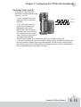
Discrete Outputs
The CTRIO module offers four discrete outputs numbered 0, 1, 2,
and 3. The outputs respond to presets assigned by the user in the
Configure IO dialog.
The presets are assigned based on the scaled value of an input, or
the raw value if it has no scaled value. The four outputs can all be
assigned to one function, or they can be grouped within functions
and within channels in any manner selected by the user.
To assign output presets, begin by selecting the ouput on the
Configure IO dialog. The outputs are identified based on terminal
number. In the example to the right, output terminal “0” is
designated for a discrete output.
Once the output selection is made, a new button
appears on the Configure IO dialog. The button is
labeled as shown to the right. The leading numeral
represents the number of the output terminal.
Clicking on the Preset button causes the Default Output Settings
dialog to pop up. Default settings are loaded on power-up.
On the Output Settings dialog, select “Use Single Preset.” We will
discuss Preset Tables later in this
chapter. Now, click OK to arrive
at the Edit Preset Entry dialog.
Six output functions are available (as shown in the
figure below). Set the preset value in engineering
units if the signal has been scaled. Set the preset
value in raw count if the signal has not been scaled.
We discuss scaling elsewhere in this chapter. Pulse ON
and Pulse OFF require a Pulse Time setting. The Pulse
Time is set in msec (1,000 sec = 1 msec)
Output Function Definitions
Set
Writes output ON (maintained)
Reset
Writes output above OFF
Pulse On
Writes output ON for specified time
Pulse Off
Writes output OFF for specified time
Toggle
Changes state of output
Reset Count
Resets the count to Preset Value
Counter I/O User Manual
3–21
Chapter 3: Configuring the CTRIO with Workbench
Creating and Using the Output
Preset Tables
To create tables of presets, click the Preset Tables
button on the main Workbench dialog. This will open
the Output Preset
Tables dialog. To
create a new table,
click Add (or Edit). This
will open the Edit Preset Table dialog.
Build a Preset Table by adding
preset entries one at a time.
Click Add Preset (or Edit Preset)
to open the Edit Preset Entry
dialog.
On the Edit Preset Entry dialog, select one of the
six Output Functions. Set the preset value in
engineering units if the signal has been scaled. Set
the preset value in raw count if the signal has not
been scaled. We discuss scaling elsewhere in this
chapter. Pulse ON and Pulse OFF require a Pulse
Time setting. The Pulse Time is set in msec (1,000
sec = 1 msec). For a description of the Output
Functions see page 3-21.
To set a particular table as the default table, use
the Default Output Settings dialog described on
page 3-21.
3–22
Counter I/O User Manual
Chapter 3: Configuring the CTRIO with Workbench
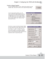
I/O Map Dialog
On the main dialog, click the I/O Map button to open the I/O
Map dialog. The I/O Map dialog performs three important
functions for users of DirectLOGIC PLCs.
First, it gives you the opportunity to assign CPU memory
locations for data transfers from the CTRIO module to the CPU
and data transfers from the CPU to the CTRIO module. The
example shown below indicates the V-memory locations of a DirectLOGIC PLC.
The I/O Map also allows you to enable these data transfers. You will need to enable the
data transfers in order to use the CTRIO data within your control program or to make
dynamic changes to the stored CTRIO data or configuration values.
The third important function of the I/O Map is to identify, in a table form, the memory
locations where raw or scaled input values are located and where status and control
bits appear.
Counter I/O User Manual
3–23
THIS PAGE INTENTIONALLY LEFT BLANK.
CHAPTER
PROGRAM CONTROL
4
1
In This Chapter...
Memory Map for Inputs from CTRIO to CPU
. . . . . . . . . . . . . . . .4–2
Memory Map for Outputs from CPU to CTRIO . . . . . . . . . . . . . . .4–3
CTRIO Input Parameter Definitions . . . . . . . . . . . . . . . . . . . . . . . .4–4
Function Status and Control Bit Definitions . . . . . . . . . . . . . . . . . .4–5
Runtime Changes to the Preset Tables
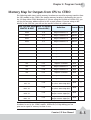
Addressing Conventions
. . . . . . . . . . . . . . . . . . . . .4–6
. . . . . . . . . . . . . . . . . . . . . . . . . . . . . . .4–9
Pulse Output Commands . . . . . . . . . . . . . . . . . . . . . . . . . . . . . .4–10
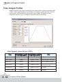
Pulse Output Profiles . . . . . . . . . . . . . . . . . . . . . . . . . . . . . . . . .4–12
Chapter 4: Program Control
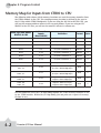
Memory Map for Inputs from CTRIO to CPU
The following table shows which memory locations are used for memory transfers from
the CTRIO module to the CPU. The starting memory location is defined by the user in
the I/O Map within CTRIO Workbench. If you are using the D2-240 or D2-250 CPU, you
will use the memory address offsets in the second column. If you are using an H2WinPLC in the CPU slot, you will use the non-PLC offsets in column one.
Data Type and Offset
WinPLC & EBC
Address for
Inputs
(DirectLOGIC)
Definition
Format
Bytes
dwX0
n+0
Ch 1/Fn 1 Parameter 1
DWord
4
dwX1
n+2
Ch 1/Fn 1 Parameter 2
DWord
4
dwX2
n+4
Ch 1/Fn 2 Parameter 1
DWord
4
dwX3
n+6
Ch 1/Fn 2 Parameter 2
DWord
4
dwX4
n+10
Ch 2/Fn 1 Parameter 1
DWord
4
dwX5
n+12
Ch 2/Fn 1 Parameter 2
DWord
4
dwX6
n+14
Ch 2/Fn 2 Parameter 1
DWord
4
dwX7
n+16
Ch 2/Fn 2 Parameter 2
DWord
4
bX0...7
bX8...15
n+20
Ch 1/Fn 1 Status (Low Byte)
Ch 1/Fn 2 Status (High Byte)
Word
2
bX16...23
bX24...31
n+21
Ch 2/Fn 1 Status (Low Byte)
Ch 2/Fn 2 Status (High Byte)
Word
2
bX32...39
bX40...47
n+22
Output 0 Status (Low Byte)
Output 1 Status (High Byte)
Word
2
bX48...55
bX56...63
n+23
Output 2 Status (Low Byte)
Output 3 Status (High Byte)
Word
2
For DirectSOFT32 users: the I/O Map dialog displays the exact memory locations in use
by the CTRIO module. Within the I/O Map dialog you can print out a report of memory
loctions in use.
4–2
Counter I/O User Manual
Chapter 4: Program Control
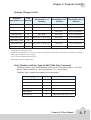
Memory Map for Outputs from CPU to CTRIO
The following table shows which memory locations are used for memory transfers from
the CPU module to the CTRIO. The starting memory location is defined by the user in
the I/O Map within CTRIO Workbench. If you are using the D2-240 or D2-250 CPU, you
will use the memory address offsets in the second column. If you are using an H2WinPLC in the CPU slot, you will use the non-PLC offsets in column one.
Data Type and Offset Addr. for Inputs
(DirectLOGIC)
WinPLC & EBC
Definition
Format Bytes
dwY0
n+0
Output 0 Parameter 3
DWord
4
dwY1
n+2
Output 1 Parameter 3
DWord
4
dwY2
n+4
Output 2 Parameter 3
DWord
4
dwY3
n+6
Output 3 Parameter 3
DWord
4
wY0
n+10
Output 0 Command
DWord
4
wY1
n+11
Output 0 Parameter 1
Word
4
wY2
n+12
Output 0 Parameter 2
Word
4
wY3
n+13
Output 1 Command
Word
4
wY4
n+14
Output 1 Parameter 1
Word
2
wY5
n+15
Output 1 Parameter 2
Word
2
wY6
n+16
Output 2 Command
Word
2
wY7
n+17
Output 2 Parameter 1
Word
2
wY8
n+20
Output 2 Parameter 2
Word
2
wY9
n+21
Output 3 Command
Word
2
wY10
n+22
Output 3 Parameter 1
Word
2
wY11
n+23
Output 3 Parameter 2
Word
2
bY0...7
bY8...15
n+24
Ch 1/Fn 1 Status (Low Byte)
Ch 1/Fn 2 Status (High Byte)
Word
2
bY16...23
bY24...31
n+25
Ch 2/Fn 1 Status (Low Byte)
Ch 2/Fn 2 Status (High Byte)
Word
2
bY32...39
bY40...47
n+26
Output 0 Status (Low Byte)
Output 1 Status (High Byte)
Word
2
bY48...55
bY56...63
n+27
Output 2 Status (Low Byte)
Output 3 Status (High Byte)
Word
2
For DirectSOFT32 users: the I/O Map dialog displays the exact memory
locations in use by the CTRIO module. Within the I/O Map dialog you can
print out a report of memory loctions in use.
Counter I/O User Manual
4–3
Chapter 4: Program Control
CTRIO Input Parameter Definitions
The following table defines the meaning of Parameter 1 and Parameter 2 under different
configuration settings. The functions listed in column one are defined by the user in
CTRIO Workbench.
Configured Function from
CTRIO Workbench
4–4
Parameter 1
Contents
DWORD
Parameter 2
Contents
DWORD
Non-scaled Counter
Raw Input Value
Not Used
Scaled Counter
Scaled Value (pos. or rate)
Raw Value
Non-scaled Counter with Capture
Raw Value
Captured Value
Scaled Counter with Capture
Scaled Value (pos. or rate)
Captured Value
Non-scaled Timer
Previous Time (us)
In Progress Time (us)
Scaled Timer
Scaled Interval (rate)
In Progress Time (us)
Pulse Catch
Not Used
Not Used
Counter I/O User Manual
Chapter 4: Program Control
Function Status and Control Bit Definitions
The table below defines the bit locations for control and status of user configured
functions. The functions are configured in CTRIO Workbench and can be controlled or
monitored from your control program. EBC users see note on page 3-20.
Control Bit
(transfers from CPU to CTRIO)
Bit Offsets
WinPLC & EBC
V-memory Offsets
DirectLOGIC PLCs
Enable Count Capture
0, 8, 16, 24
24.0, 24.8, 25.0, 25.8
Scaled Counter
0, 8, 16, 24
24.0, 24.8, 25.0, 25.8
Enable Pulse Catch
0, 8, 16, 24
24.0, 24.8, 25.0, 25.8
Reset
1, 9, 17, 25
24.1, 24.9, 25.1, 25.9
Status Bit
(transfers from CTRIO to CPU)
Bit Offsets
WinPLC & EBC
V-memory Offsets
DirectLOGIC PLCs
Count Capture Complete Bit
0, 8, 16, 24
20.0, 20.8, 21.0, 21.8
Timer Capture Start
0, 8, 16, 24
20.0, 20.8, 21.0, 21.8
Timer Capture Complete (Timing) OR
At Reset Value (Counting)
1, 9, 17, 25
20.1, 20.9, 21.1, 21.9
Pulse Catch Output Pulse State
0, 8, 16, 24
20.0, 20.8, 21.0, 21.8
Pulse Catch Start
1, 9, 17, 25
20.1, 20.9, 21.1, 21.9
Counter I/O User Manual
4–5
Chapter 4: Program Control
Runtime Changes to the Preset Tables
Presets and preset tables can be set up entirely within CTRIO Workbench. You can also
make runtime edits to presets from your control program. To make a runtime change, a
series of commands must be executed which will pass new values to a preset table (or
call a different preconfigured table).
Command Codes are passed to the CTRIO module to effect the required edit. Each
Command Code has its own syntax, and all Command Codes must be presented in a
particular sequence:
The command code and associated parameters must be loaded into the appropriate
memory locations.
A Process Command instruction must be passed to the CTRIO module.
A Command Complete signal must be received and the Command Error bit must stay
at zero.
Finally, the Enable Output instruction must be passed to the CTRIO module.
Some changes require a combination of Command Codes so those changes must follow
the steps above for each Command Code processed.
Control Bit
Enable Output
32, 40, 48, 56
26.0, 26.8, 27.0, 27.8
Process Command
39, 47, 55, 63
26.7, 26.15, 27.7, 27.15
Status Bit
4–6
Bit Y Offsets V-memory Offsets
WinPLC & EBC
DirectLOGIC PLCs
Bit X Offsets
WinPLC & EBC
V-memory Offsets
DirectLOGIC PLCs
Count Capture Complete Bit
38, 46, 54, 62
22.6, 22.14, 23.6, 23.14
Timer Capture Start
39, 47, 55, 63
22.7, 22.15, 23.7, 23.15
Counter I/O User Manual
Chapter 4: Program Control
Runtime Changes Cont’d
Command
DirectLOGIC n+10
Code
Hex/BCD
Parameter 1 (Word)
DirectLOGIC n+11
(decimal)
Parameter 2 (Word) Parameter 3 (DWord)
DirectLOGIC n+12 DirectLOGIC n+0/n+1
(decimal)
(decimal)
Load Table from RAM
10
File Number
-
Clear RAM Table
11
-
-
-
Initialize RAM Table
12
Entry Type
Pulse Time
Add Table Entry
13
Entry Type
Pulse Time
2
Edit Table Entry
2
3
2
3
File & 14 Entry Num. & Entry Type
Write RAM to ROM
5
-
99
2
Edit and Reload
30
1
1
Preset Count/Time
Preset Count/Time
Preset Count/Time
-
File & 15 Entry Num. & Entry Type
Edit Level Response
Pulse Time
1
Level Behavior
4
4
4
-
Pulse Time
1
Deadband
Preset Count/Time
4
Level Rate Setting
1
If appropriate for Entry Type (in ms).
2
Field entries separated by an “&” are to be loaded in the high byte and low byte of that word (See example on next page).
3
Entry types are defined on the next page.
4
Follows format of Input DWord Parameter 1.
5
Flash ROM is rated for 100,000 writes.
Entry Number and Entry Type for Edit Table Entry Command
The Entry Number refers to the position of the preset in the table sequence. The first
preset is Entry Number “0,” the second preset is “1,” and so forth.
The Entry Type is defined according to the table below.
Entry Type
Code
Notes
Write Output ON (Set)
0
-
Write Output OFF (Reset)
1
-
Pulse Output ON
2
-
Pulse Output OFF
5
-
Toggle Output
4
-
Reset Function
5
Edits preset that resets count
Counter I/O User Manual
4–7
Chapter 4: Program Control
Edit Level Response Command
If a Counter or Timer function is scaled to produce a rate, alarm level settings can be
used to trigger discrete outputs at values predetermined by the user. The alarm levels
can be set within CTRIO Workbench or from the user’s control program.
Additionally, a deadband percentage (in tenths of a percent) can be set to prevent the
output from changing too frequently near the Rate Level threshold. Consider a Discrete
Output set to turn ON when a level gets to 100 with a 10% deadband. The output will
turn ON when the level gets to 100. If the level drops, the output will stay on until the
level drops below 90, where it will turn OFF.
Edit the behavior of a Discrete Output triggered by a Rate Level by using the “Edit Level
Response Command” (Command Code 20Hex).
The Level Behavior setting for Parameter 1 is given in the table below:
Level Behavior
for Discrete Output
Parameter 1
Contents
Notes
ON when greater than Level Rate setting
0000 Hex
-
ON when less than Level Rate setting
0001 Hex
-
OFF when greater than Level Rate setting
0080 Hex
-
OFF when less than Level Rate setting
0081 Hex
-
The Deadband is written to Parameter 2 as a x10 integer (one implied decimal position).
To achieve a 10.0% deadband, the control program needs to write 100 decimal (64
Hex) to Parameter 2.
The Level Rate setting is written to Parameter 3 in the same format as Input Parameter 1
of the CTRIO Function to which this Discrete Output has been assigned.
4–8
Counter I/O User Manual
Chapter 4: Program Control
Addressing Conventions
(with V-memory Examples for DirectLOGIC PLCs)
Example for Bit-accessed Data in PLC CPUs
In this example, the V-memory location V2524 contains a value equal to 514 in
decimal.
514 decimal = 0202 Hex = 0000 0010 0000 0010 binary
The bit V2524.1 refers to the 2nd to the least significant bit (set to 1 in this example).
Likewise, V2524.9 refers to bit number 9, the 10th from the least significant bit (also set
to 1 in this example).
Bit
15
14
13
12
11
10
9
8
7
6
5
4
3
2
1
0
V2524
0
0
0
0
0
0
1
0
0
0
0
0
0
0
1
0
V2524.9 = 1
V2524.1 = 1
Addressing High and Low Byte of Word Parameters
In the following example, the V-memory location V2510 contains a value equal to 3
(decimal) in the high byte and 10 (decimal) in the low byte.
3 decimal = 03 Hex = 0000 0011 binary in the high byte, and
10 decimal = 0A Hex = 0000 1010 binary in the low byte.
This example could represent the Command Code “Edit Table Entry.” The value 03
(Hex) would represent the File number in the high byte, and the 0A (Hex) would
represent the remainder of the Command Code in the low byte.
High Byte
Low Byte
Bit
15
14
13
12
11
10
9
8
7
6
5
4
3
2
1
0
V2510
0
0
0
0
0
0
1
1
0
0
0
0
1
0
1
0
High Nibble
Low Nibble
High Nibble
Low Nibble
Addressing High and Low Word of DWord Parameters
Double Word parameters are addressed in a similar fashion to the high and low bytes of
a Word Parameter. For example, a DWord that begins in V2300 consumes both V2300
and V2301. The Low Word is V2300, and the High Word is V2301.
Counter I/O User Manual
4–9
Chapter 4: Program Control
Pulse Output Commands
The CTRIO module can generate Pulse Outputs based
on predefined user profiles. Using program control
techniques, the Pulse Profiles can also be changed
dynamically during runtime.
CTRIO Workbench can create a maximum of 255
predefined Pulse Profiles. The total number of Pulse
Profiles available is 255 minus the number of
predefined Preset Tables. Pulse Profiles and Preset
Tables are saved as File 1 through File 255.
Based on the Workbench configuration, either of the
two Pulse Output channels can output Pulses and
Direction, or Up Pulses and Down Pulses.
Control Bit
CPU to CTRIO
ory Offsets
Bit Offsets fromVOmuetm
put Start (octal)
Enable Output
32, 48
26.0, 27.0
Level
Output Direction (1= CCW)
33, 49
26.1, 27.1
Level
Load and Seek New Dynamic Position
34, 50
26.2, 27.2
Rising Edge
Process Command
39, 55
26.7, 27.7
Rising Edge
Status Bit
CTRIO to CPU
Bit Offsets
V memory Offsets
from Input Start (octal)
Pulae Active
32, 48
22.0, 23.0
Pulse Error by CTRIO
33, 49
22.1, 23.1
New Dynamic Position Loaded
34, 50
22.2, 23.2
Command Error
38, 54
22.6, 23.6
Command Complete
39, 55
22.7, 23.7
Word Control
CPU to CTRIO
Word Offsets
V-memory Offsets
from Output Start (octal)
Command Code
0, 6
10, 16
Word Parameter 1
1, 7
11, 17
Word Parameter 2
2, 8
12, 20
DWord Control
CPU to CTRIO
DWord Parameter 1
4–10
Read as:
Counter I/O User Manual
Word Offsets
0, 2
V-memory Offsets
from Output Start (octal)
0, 4
Chapter 4: Program Control
Cont’d
Command
Code
Load Profile from ROM
1
Load Profile from ROM
1
Pulse Output at Velocity
5
Pulse Output to Limit
6
Pulse Output to Position
7
Word Parameter 1
Trapezoid or S-curve
File Number
Dynamic Positioning
File Number
Run Frequency
(20Hz - 25KHz)
Run Frequency
(20Hz - 25KHz)
Run Frequency
(20Hz - 25KHz)
Word Parameter 2
DWord Parameter 3
-
-
-
New Position
Duty Cycle (0 to 99)*
Number of Pulses
Edge &
Duty Cycle (0 to 99)*
Compare Function &
Duty Cycle (0 to 99)*
Desired Input Function
Value
-
* A value of 0 will generate a duty cycle of 50%
Fields above separated by an “&” indicate a code with different definitions for each byte
(high byte and low byte). For example, to enter the Pulse Output to Limit command, set
the high byte of the Word Parameter 2 to the edge you wish to terminate the output
pulses (see definition following), and set the low byte to the desired duty cycle.
In order to process a command, first the program must load the Command Code and
required DWord, Word, and bit parameters. Then the program should drive the Process
Command bit to a 1 and look for the CTRIO to acknowledge the command with the
Command Complete bit. Finally, the program should remove the Process Command bit
and set the Enable Output bit when appropriate. If the Command Error bit is received,
the CTRIO was unable to process the command due to n illegal value in either the
Command Code or parameter files.
DWord and Word values for pulse outputs are considered unsigned integers.
Counter I/O User Manual
4–11
Chapter 4: Program Control
Pulse Output Profiles
Loading a profile is the easiest method for pulse output motion control (Command Code
= 0001). All the characteristics of acceleration, run frequency, and total pulse count are
entered in the CTRIO Workbench Pulse Profile entry window. The profile can be a
Trapezoid, Velocity S-Curve, or program controlled Dynamic Positioning.
Status Registers (status bit from CTRIO)
Name
PLC Example 1: V2000 PLC Example 2: V40600
as Base Input Address
as Base Input Address
Value
Output Enabled
V2022.0
V40622.0 or C440
ON when Enable Output is ON
Position Loaded
V2022.1
V40622.1 or C441
Used for Dynamic Positioning
Output Active
V2022.4
V40622.4 or C444
ON when Output is Pulsing
Output Stalled
V2022.5
V40622.5 or C445
CTRIO Output Fault
(should never be ON)
Command Error
V2022.6
V40622.6 or C446
ON if Command or Parameters
are invalid
Command Complete
V2022.7
V40622.7 or C447
ON if Module Receives Process
Command
4–12
Counter I/O User Manual
Chapter 4: Program Control
Control Registers (control DWords, Words, and bits
Name
PLC Example 1: V2000 PLC Example 1: V40600 # Format
as Base Output Address as Base Output Address
Command Code
V2040
V40660
Decimal
Parameter 1
V2041
V40661
Decimal
Parameter 2
V2042
V40662
Decimal
Parameter 3
V2031 / V2030
V40651-50
Signed
Decimal
Enable Output
V2056.0
V40676.0 or C1740
Decimal
Go to Position
V2056.1
V40676.1 or C1741
Decimal
Direction
V2056.4
V40676.4 or C1744
Decimal
Process Command
V2056.7
V40676.7 or C1747
Decimal
Counter I/O User Manual
4–13
Chapter 4: Program Control
Trapezoid or S-Curve
For predefined Trapezoid or S-Curve profiles, the program needs to prepare the Load
Table command by selecting Command Code = 1 and setting Word Parameter 1 to the
File number of the profile (example: File 1 Trapezoid 1). Then the program can set the
Process Command bit and watch for the Command Complete bit. Then the program
should clear the Process Command bit and set the Direction bit and finally the Enable
Output bit to start the output pulses. Clearing the Enable Output bit will always suspend
pulsing and reset any profile in progress to it’s beginning . Once complete, the profile
remains loaded and can be restarted buy clearing the Enable Output, changing the
direction bit (if desired), and again setting the Enable Output.
Easy step examples are given for PLCs with CTRIO I/O date mapped in the word and CR
bit areas of CPU menmory.
Running a Trapezoid or S-Curve Profile on CTRIO Y0 & Y1
PLC
PLC
Control PLICnpSutatstus
Control PLICnpSutatstus O
Outputs Base Addr BasuetpAudtdsr Base Addr
Base Addr = V2000 = V40650 = V40600
= V2030
(C0)
(C1200)
Steps
Name
1
Command
Code
V2040
V40660
Set to 1
(Load Stored Profile)
2
Parameter 1
V2041
V40661
File # of stored profile,
determined by user
3
Process
Command
V2056.7
V40676.7 or
C1747
4
Command
Status
5
Set Direction
V2056.4
6
Enable
Output
V2056.0
7
Enable
Status
V2022.0
V40622.0 or
C440
When ON, module is
confirming Enable Output
8
Output
Status
V2022.4
V40622.4 or
C444
When ON, module is
pulsing, OFF with Enable
Status ON = profile has
completed
9
Disable
Output
V40622.7 or
C447
V2022.7
V2022.7
V2056.0
Counter I/O User Manual
Turn ON until Command
Complete status bit is
returned (see step 4)
When ON, Profile is now
loaded, clear Process
Command bit (step 3)
V40676.1 or
C1741
Set ON or OFF for
Direction of Rotation
V40676.0 or
C1740
Turn ON to start pulses
V40676.0 or
C1740
To re-launch a loaded profile, repeat steps 5-9
4–14
Action
Turn OFF when pulse
status is OFF and Enable
Status is ON
Chapter 4: Program Control
Dynamic Positioning
For Dynamic Positioning, only the motion limits of Min Frequency, Max Frequency, and
Max Acceleration come from the CTRIO Workbench Profile. After loading a Dynamic
Position Profile per the above paragraph, setting the Enable Output causes the CTRIO
module to assume a position of 0 pulses. The program should write the next target
position in DWord Parameter 3, and set the Load/Seek Position bit. This will cause the
CTRIO to set both the Pulses Active and the New Position Loaded bit and begin output
pulses (with the proper direction setting) to achieve the new position.
The program can monitor the state of the Pulses Active bit and the New Position Loaded
bit to determine when the new position has been attained. The New Position Loaded
status bit will always follow the s tate of the Load/Seek New Position control bit. This
status bit should be used to signal the program that the CTRIO has received the new
state of the control bit.
Position Loaded Status Bit
V40622.1 or C441
Pulses Active Status Bit
V40622.0 or c440
CTRIO Dynamic Position
Pulse Output State
0
0
Idle
1
1
Go To Position Acknowledged,
Pulsing
0
1
Still Pulsing, Go To Position
Control Bit is OFF
1
0
Go To Position Acknowledged,
Position Attained
After the GoTo Position is acknowledged, the program can load the next position into the
DWord Parameter 3. When Pulses Active Status goes to 0, then setting the GoTo Position
control bit will again start the output toward the new position. The CTRIO moves to the
new position relative to its previous position as long as the Enable Output control bit
remains set. Clearing the Enable Output bit will disable output pulsing and reset the
current position to 0.
Counter I/O User Manual
4–15
Chapter 4: Program Control
Dynamic Positioning using the CTRIO Y0 and Y1
PLC
PLC
Control PLICnpSutatstus
Control PLICnpSutatstus O
Outputs Base Addr BasuetpAudtdsr Base Addr
Base Addr = V2000 = V40650 = V40600
= V2030
(C0)
(C1200)
Steps
Name
1
Command
Code
V2040
V40660
Set to 1
(Load Stored Profile)
2
Parameter 1
V2041
V40661
File # containing Vmin,
Vmax, and Accel
3
Process
Command
V2056.7
V40676.7 or
C1747
4
Command
Status
5
Enable
Output
6
Enable
Status
7
Parameter 3
V2031 /
V2030
V40662 /
V40661
Target position: User
defined (DWord)
8
Go To
Position
V2056.1
V40676.1 or
C1741
Starts pulses with direction
to obtain the new position
relative to previous
position.
9
Position
Loaded
Status
10
Output
Active Status
11
Go To
Position
V40622.7 or
C447
V2022.7
When ON, pulses are now
V40622.7 or
enabled and last position is
C447
retained
V2022.7
V2022.1
V40662.1 or
C444
When ON, Go To position
is acknowledged
V2022.4
V40662.1 or
C444
When ON, module is
pulsing, OFF with Position
Loaded status ON = new
position move has
completed
V2056.1
V40676.1 or
C1741
To seek the next position, repeat steps 7-10.
4–16
Turn ON until Command
Complete status bit is
returned (see step 4)
When ON, Profile is now
loaded, clear Process
Command bit (step 3)
Turn ON to assume 0
position, Turn OFF to
disable pulses and zero
position
V40676.0 or
C1740
V2056.0
Action
Counter I/O User Manual
Turn OFF to be ready to
load a new position
Chapter 4: Program Control
Pulse Output at Velocity
For motion control directly from the CPU/controller program, use the Pulse Output at
Velocity command (Command = 0005). The Number of Pulses can be set to “FFFFFFFF”
in Hex for unlimited pulse counts. Leaving the Duty Cycle set to 0 achieves the default
(50%), otherwise in can be set in 1% increments by writing this value from 1 to 99
decimal. After this command is processed, the Run Frequency and Duty Cycle fields can
be adjusted by direct access. In order to change directions from Pulse Output in
“Velocity” mode, the Enable Output bit must first be cleared (which stops the Pulse
Outputs). Then after the new direction bit is written, the Enable Output bit can be set to
resume pulsing.
Steps: PLC Address V40650and module channel 1 is used for the CTRIO base output
address for all examples in this Doc.
Run Velocity control on CTRIO Y0 &Y1
PLC
PLC
Control PLICnpSutatstus
Control PLICnpSutatstus O
Outputs Base Addr BasuetpAudtdsr Base Addr
Base Addr = V2000 = V40650 = V40600
= V2030
(C0)
(C1200)
Steps
Name
1
Command
Code
V2040
V40660
2
Parameter 1
V2041
V40661
3
Parameter 2
V2042
V40662
4
Parameter 3
V2031 /
V2030
V40662 /
V40661
5
Set Direction
V2056.4
V40676.1 or
C1741
6
Process
Command
V2056.7
V40676.7 or
C1747
7
Command
Status
8
9
Enable
Output
Disable
Output
V2056.0
V2056.0
Set to 5
(Pulse at Velocity)
Set initial run frequency
(20Hz-25000Hz)
Duty cycle (1-99) (can leave
0 for 50%)
Number of pulses (DWord)
set to FFFF FFFF for no
limit
Set ON or OFF for
Direction of Rotation
Turn ON Command
Complete status bit is
returned (see step 4)
V40622.7 or
C447
V2022.7
V40676.0 or
C1740
V40676.0 or
C1740
Action
When ON, command has
been accepted, clear
Process Command bit
(step 3)
Turn ON to start pulses
Turn OFF to start pulses
While Velocity Control is running, Run Frequency (step 2) and Duty Cycle (step 3) may be
actively adjusted simply by writing the variable.
Counter I/O User Manual
4–17
Chapter 4: Program Control
Pulse Output to Input Limit
The Pulse Output to Limit (Command = 6) can be used for Home Search routines where
a relatively low frequency is used to seek a CTRIO discrete input. The CTRIO input must
be assigned for Limit by the CTRIO Workbench utility.
As with Pulse Output at Velocity, set Word Parameter 1 to the desired frequency, Word
Parameter 2 Low Byte to the Duty Cycle, and the High Byte to the Edge to Seek.
The Edge to Seek field reads Word Parameter 2 bits 13 and 12 to determine the edge(s)
on which to terminate Output Pulses, and bits 9 and 8 to determine which CTRIO Input
terminal to use.
Edge(s)
Bits 15..12
CTRIO Input
Rising
0000, 0Hex
Ch 1 C
0000, 0Hex
Falling
0001, 1Hex
Ch 1 D
0001, 1Hex
Both
0010, 2Hex
Ch 2 C
0010, 2Hex
Ch 2 D
0011, 3Hex
Bits 11..8
Example 1: To run to a Rising Edge Limit on Channel 1’s C Input at 50% Duty Cycle, use
Word Parameter 2 = 0000 Hex. (Duty Cycle = 00 also creates 50% duty)
Example 2: To run to a Falling Edge Limit on Channel 2’s C Input at 20% Duty Cycle, use
Word Parameter 2 = 1214 Hex.
Run Velocity on CTRIO Y0 & Y1 until Discrete Input Limit
4–18
PLC
PLC
Control PLICnpSutatstus
Control PLICnpSutatstus O
utputs
Outputs
ase Addr
se Addr Base Addr B
Base Addr B=aV
=
V40600
2000 = V40650
= V2030
(C0)
(C1200)
Steps
Name
1
Command
Code
V2040
V40660
2
Parameter 1
V2041
V40661
3
Parameter 2
V2042
V40662
4
Set Direction
V2056.4
V40676.1 or
C1741
5
Process
Command
V2056.7
V40676.7 or
C1747
6
Command
Status
7
Enable
Output
8
Output
Active Status
Set to 6
(Pulse at velocity until
discret input limit))
Set initial run frequency
(20Hz-25000Hz)
Select discrete input edge
in high byte, low byte =
duty cycle (1-99)
Example: rising input 1D at
Duty = 45%, set this
parameter to 212D Hex
Set ON or OFF for
Direction of Rotation
Turn ON until Command
Complete status bit is
returned (see step 4)
V40622.7 or
C447
V2022.7
V40676.0 or
C1740
V2056.0
V2022.4
Counter I/O User Manual
Action
When ON, command has
been accepted, clear
Process Command bit
(step 3)
Turn ON to start pulses
V40622.4 or
C444
ON while pulsing, OFF
when limit has stopped
pulsing
Chapter 4: Program Control
Pulse Output to Position
The Pulse Output to Position command (Command = 7) allows Pulse Outputs that
terminate when a specific Input Function Value is obtained. Set Word Parameter 1 to the
desired Frequency (As with Velocity and Run to Limit). Set Word Parameter 2 Low Byte to
the Duty Cycle and the High Byte to the Compare Function as defined below.
The Compare Function field defines either greater or less than any of the four CTRIO
Input Function Values. The compare will take place against Input DWord Parameter 1 of
the selected Function. The CTRIO reads command code bit 12 to determine if the
compare is “greater than or equal” or “less than”. It reads bits 9 and 8 to determine the
Input Function to use for comparison.
Input Function
Bits 11..8
Comparison
Bits 15..12
Ch 1 Fn 1
0000, 0Hex
Greater Than or Equal
0000, 0Hex
Ch 1 Fn 2
0001, 1Hex
Less Than
0001, 1Hex
Ch 2 Fn 1
0010, 2Hex
Ch 2 Fn 2
0011, 3Hex
Run Velocity on CTRIO until Function Input Value
PLC
PLC
Control PLICnpSutatstus
Control PLICnpSutatstus O
utputs
Outputs
ase Addr
se Addr Base Addr B
Base Addr B=aV
=
V40600
2000 = V40650
= V2030
(C0)
(C1200)
Steps
Name
1
Command
Code
V2040
V40660
2
Parameter 1
V2041
V40661
3
Parameter 2
V2042
V40662
4
Parameter 3
V2031 /
V2030
5
Set Direction
V2056.4
6
Process
Command
V2056.7
V40651 /
V40650
V40676.1 or
C1741
V40676.7 or
C1747
7
Command
Status
8
9
Enable
Output
Output
Active Status
V2022.7
Set to 6
(Pulse at velocity until Function
Input Limit)
Set initial run frequency
(20Hz-25000Hz)
Select discrete input edge in high
byte, low byte = duty cycle (1-99)
Example: rising input 1D at Duty =
45%, set this parameter to 212D
Hex
Function DWord value for
comparison
Set ON or OFF for
Direction of Rotation
Turn ON until Command Complete
status bit is returned (see step 4)
When ON, command has been
V40622.7 or
accepted, clear
C447
Process Command bit (step 3)
V40676.0 or
C1740
V2056.0
V2022.4
Action
Turn ON to start pulses
V40622.4 or
C444
ON while pulsing, OFF when limit
has stopped pulsing
While Run Velocity to Function Input Value is running, Run Frequency (Step 2) and Duty
Cycle(Step 3) may be actively adjusted simply by writing the variable.
Example: To run a Pulse Output at 30% duty until Ch2 Fn 1 is at 100,000, write 100,000
to DWord Parameter 3, set the desired Frequency in Word Parameter 1, set Word
Parameter 2 to 12E Hex (Hex 1E = 30% Decimal), set the proper direction bit, then
load and execute Command Code = 7, and finally set the Enable Output bit. The
Output will Pulse until Ch2 Fn1’s Input DWord Parameter 1 gets to 100,000.
Counter I/O User Manual
4–19