1
CTRIO
High-Speed Counter
Module
Manual Number: HX-CTRIO-M
WARNING Thank you for purchasing automation equipment from Automationdirect.com®, doing business as,
AutomationDirect. We want your new automation equipment to operate safely. Anyone who installs or
uses this equipment should read this publication (and any other relevant publications) before installing or
operating the equipment.
To minimize the risk of potential safety problems, you should follow all applicable local and national codes
that regulate the installation and operation of your equipment. These codes vary from area to area and
usually change with time. It is your responsibility to determine which codes should be followed, and to
verify that the equipment, installation, and operation is in compliance with the latest revision of these
codes.
At a minimum, you should follow all applicable sections of the National Fire Code, National Electrical
Code, and the codes of the National Electrical Manufacturer's Association (NEMA). There may be local
regulatory or government offices that can also help determine which codes and standards are necessary for
safe installation and operation.
Equipment damage or serious injury to personnel can result from the failure to follow all applicable codes
and standards. We do not guarantee the products described in this publication are suitable for your
particular application, nor do we assume any responsibility for your product design, installation, or
operation.
Our products are not fault-tolerant and are not designed, manufactured or intended for use or resale as online control equipment in hazardous environments requiring fail-safe performance, such as in the
operation of nuclear facilities, aircraft navigation or communication systems, air traffic control, direct life
support machines, or weapons systems, in which the failure of the product could lead directly to death,
personal injury, or severe physical or environmental damage ("High Risk Activities"). AutomationDirect
specifically disclaims any expressed or implied warranty of fitness for High Risk Activities.
For additional warranty and safety information, see the Terms and Conditions section of our catalog. If
you have any questions concerning the installation or operation of this equipment, or if you need
additional information, please call us at 770-844-4200.
This publication is based on information that was available at the time it was printed. At
AutomationDirect we constantly strive to improve our products and services, so we reserve the right to
make changes to the products and/or publications at any time without notice and without any obligation.
This publication may also discuss features that may not be available in certain revisions of the product.
Trademarks
This publication may contain references to products produced and/or offered by other companies. The
product and company names may be trademarked and are the sole property of their respective owners.
AutomationDirect disclaims any proprietary interest in the marks and names of others.
Copyright 2012, Automationdirect.com® Incorporated
All Rights Reserved
No part of this manual shall be copied, reproduced, or transmitted in any way without the prior, written
consent of Automationdirect.com® Incorporated. AutomationDirect retains the exclusive rights to all
information included in this document.
ADVERTENCIA Gracias por comprar equipo de automatización de Automationdirect.com®. Deseamos que su nuevo equipo de
automatización opere de manera segura. Cualquier persona que instale o use este equipo debe leer esta
publicación (y cualquier otra publicación pertinente) antes de instalar u operar el equipo.
Para reducir al mínimo el riesgo debido a problemas de seguridad, debe seguir todos los códigos de seguridad
locales o nacionales aplicables que regulan la instalación y operación de su equipo. Estos códigos varian de área
en área y usualmente cambian con el tiempo. Es su responsabilidad determinar cuales códigos deben ser
seguidos y verificar que el equipo, instalación y operación estén en cumplimiento con la revisión mas reciente
de estos códigos.
Como mínimo, debe seguir las secciones aplicables del Código Nacional de Incendio, Código Nacional
Eléctrico, y los códigos de (NEMA) la Asociación Nacional de Fabricantes Eléctricos de USA. Puede haber
oficinas de normas locales o del gobierno que pueden ayudar a determinar cuales códigos y normas son
necesarios para una instalación y operación segura.
Si no se siguen todos los códigos y normas aplicables, puede resultar en daños al equipo o lesiones serias a
personas. No garantizamos los productos descritos en esta publicación para ser adecuados para su aplicación en
particular, ni asumimos ninguna responsabilidad por el diseño de su producto, la instalación u operación.
Nuestros productos no son tolerantes a fallas y no han sido diseñados, fabricados o intencionados para uso o
reventa como equipo de control en línea en ambientes peligrosos que requieren una ejecución sin fallas, tales
como operación en instalaciones nucleares, sistemas de navegación aérea, o de comunicación, control de tráfico
aéreo, máquinas de soporte de vida o sistemas de armamentos en las cuales la falla del producto puede resultar
directamente en muerte, heridas personales, o daños físicos o ambientales severos ("Actividades de Alto Riesgo").
Automationdirect.com específicamente rechaza cualquier garantía ya sea expresada o implicada para
actividades de alto riesgo.
Para información adicional acerca de garantía e información de seguridad, vea la sección de Términos y
Condiciones de nuestro catálogo. Si tiene alguna pregunta sobre instalación u operación de este equipo, o si
necesita información adicional, por favor llámenos al número 770-844-4200 en Estados Unidos.
Esta publicación está basada en la información disponible al momento de impresión.
En
Automationdirect.com nos esforzamos constantemente para mejorar nuestros productos y servicios, así que
nos reservamos el derecho de hacer cambios al producto y/o a las publicaciones en cualquier momento sin
notificación y sin ninguna obligación. Esta publicación también puede discutir características que no estén
disponibles en ciertas revisiones del producto.
Marcas Registradas
Esta publicación puede contener referencias a productos producidos y/u ofrecidos por otras compañías. Los nombres de las
compañías y productos pueden tener marcas registradas y son propiedad única de sus respectivos dueños. Automationdirect.com,
renuncia cualquier interés propietario en las marcas y nombres de otros.
PROPIEDAD LITERARIA 2012, AUTOMATIONDIRECT.COM® INCORPORATED
Todos los derechos reservados
No se permite copiar, reproducir, o transmitir de ninguna forma ninguna parte de este manual sin previo consentimiento por escrito de
Automationdirect.com® Incorprated. Automationdirect.com retiene los derechos exclusivos a toda la información incluida en este
documento. Los usuarios de este equipo pueden copiar este documento solamente para instalar, configurar y mantener el equipo
correspondiente. También las instituciones de enseñanza pueden usar este manual para propósitos educativos.
AVERTISSEMENT Nous vous remercions d'avoir acheté l'équipement d'automatisation de Automationdirect.com®, en faisant des
affaires comme, AutomationDirect. Nous tenons à ce que votre nouvel équipement d'automatisation fonctionne en
toute sécurité. Toute personne qui installe ou utilise cet équipement doit lire la présente publication (et toutes les
autres publications pertinentes) avant de l'installer ou de l'utiliser.
Afin de réduire au minimum le risque d'éventuels problèmes de sécurité, vous devez respecter tous les codes locaux et
nationaux applicables régissant l'installation et le fonctionnement de votre équipement. Ces codes diffèrent d'une
région à l'autre et, habituellement, évoluent au fil du temps. Il vous incombe de déterminer les codes à respecter et
de vous assurer que l'équipement, l'installation et le fonctionnement sont conformes aux exigences de la version la
plus récente de ces codes.
Vous devez, à tout le moins, respecter toutes les sections applicables du Code national de prévention des incendies,
du Code national de l'électricité et des codes de la National Electrical Manufacturer's Association (NEMA). Des
organismes de réglementation ou des services gouvernementaux locaux peuvent également vous aider à déterminer
les codes ainsi que les normes à respecter pour assurer une installation et un fonctionnement sûrs.
L'omission de respecter la totalité des codes et des normes applicables peut entraîner des dommages à l'équipement
ou causer de graves blessures au personnel. Nous ne garantissons pas que les produits décrits dans cette publication
conviennent à votre application particulière et nous n'assumons aucune responsabilité à l'égard de la conception, de
l'installation ou du fonctionnement de votre produit.
Nos produits ne sont pas insensibles aux défaillances et ne sont ni conçus ni fabriqués pour l'utilisation ou la revente
en tant qu'équipement de commande en ligne dans des environnements dangereux nécessitant une sécurité absolue,
par exemple, l'exploitation d'installations nucléaires, les systèmes de navigation aérienne ou de communication, le
contrôle de la circulation aérienne, les équipements de survie ou les systèmes d'armes, pour lesquels la défaillance du
produit peut provoquer la mort, des blessures corporelles ou de graves dommages matériels ou environnementaux
(«activités à risque élevé»). La société AutomationDirect nie toute garantie expresse ou implicite d'aptitude à
l'emploi en ce qui a trait aux activités à risque élevé.
Pour des renseignements additionnels touchant la garantie et la sécurité, veuillez consulter la section Modalités et
conditions de notre documentation. Si vous avez des questions au sujet de l'installation ou du fonctionnement de cet
équipement, ou encore si vous avez besoin de renseignements supplémentaires, n'hésitez pas à nous téléphoner au
770-844-4200.
Cette publication s'appuie sur l'information qui était disponible au moment de l'impression. À la société
AutomationDirect, nous nous efforçons constamment d'améliorer nos produits et services. C'est pourquoi nous
nous réservons le droit d'apporter des modifications aux produits ou aux publications en tout temps, sans préavis ni
quelque obligation que ce soit. La présente publication peut aussi porter sur des caractéristiques susceptibles de ne
pas être offertes dans certaines versions révisées du produit.
Marques de commerce
La présente publication peut contenir des références à des produits fabriqués ou offerts par d'autres entreprises. Les
désignations des produits et des entreprises peuvent être des marques de commerce et appartiennent exclusivement à
leurs propriétaires respectifs. AutomationDirect nie tout intérêt dans les autres marques et désignations.
Copyright 2012, Automationdirect.com® Incorporated
Tous droits réservés
Nulle partie de ce manuel ne doit être copiée, reproduite ou transmise de quelque façon que ce soit sans le
consentement préalable écrit de la société Automationdirect.com® Incorporated. AutomationDirect conserve les
droits exclusifs à l'égard de tous les renseignements contenus dans le présent document.
Notes
CTRIO HIGH-SPEED COUNTER USER MANUAL
Please include the Manual Number and the Manual Issue, both shown below,
when communicating with Technical Support regarding this publication.
Manual Number:
HX-CTRIO-M
Issue:
Second Edition, Rev. D
Issue Date:
02/13
Publication History
Issue
Date
Description of Changes
First Edition
9/01
Original
Rev. A
10/01
Corrections
Rev. B
8/02
Corrections
Second Edition
2/03
Added T1H-CTRIO and H4-CTRIO. Updated for CTRIO/Workbench version 2.
Rev. A
10/03
Added H0-CTRIO and flowcharts.
Rev. B
10/03
Corrections
Rev. C
03/11
Made corrections and updated manual.
02/13
Updated manual with new H0-CTRIO2 and H2-CTRIO2 information.
Added Do-more PLC series data and examples.
Updated CTRIO Workbench section with new pulse profiles available.
Made minor corrections throughout manual.
Rev. D
Notes
TABLE OF CONTENTS
Chapter 1: Introduction to the CTRIO & CTRIO2 Modules
CTRIO and CTRIO2 Module Overview . . . . . . . . . . . . . . . . . . . . . . . . . . . . . . . . . . . .1–2
CTRIO Workbench . . . . . . . . . . . . . . . . . . . . . . . . . . . . . . . . . . . . . . . . . . . . . . . . . . .1–2
CTRIO Configuration . . . . . . . . . . . . . . . . . . . . . . . . . . . . . . . . . . . . . . . . . . . . . . . . .1–2
CTRIO Functions . . . . . . . . . . . . . . . . . . . . . . . . . . . . . . . . . . . . . . . . . . . . . . . . . . . .1–3
Typical Counter Applications: . . . . . . . . . . . . . . . . . . . . . . . . . . . . . . . . . . . . . . . . . . .1–4
Support Systems for the CTRIO Modules . . . . . . . . . . . . . . . . . . . . . . . . . . . . . . . . . .1–4
H0-CTRIO(2) . . . . . . . . . . . . . . . . . . . . . . . . . . . . . . . . . . . . . . . . . . . . . . . . . . . . . . .1–4
H2-CTRIO(2) . . . . . . . . . . . . . . . . . . . . . . . . . . . . . . . . . . . . . . . . . . . . . . . . . . . . . . .1–4
H4-CTRIO . . . . . . . . . . . . . . . . . . . . . . . . . . . . . . . . . . . . . . . . . . . . . . . . . . . . . . . . . .1–4
T1H-CTRIO . . . . . . . . . . . . . . . . . . . . . . . . . . . . . . . . . . . . . . . . . . . . . . . . . . . . . . . . .1–4
CTRIO Specifications . . . . . . . . . . . . . . . . . . . . . . . . . . . . . . . . . . . . . . . . . . . . . . . . . .1–5
H0-CTRIO(2) LED Indicators . . . . . . . . . . . . . . . . . . . . . . . . . . . . . . . . . . . . . . . . . . . .1–7
H2-CTRIO(2) LED Indicators . . . . . . . . . . . . . . . . . . . . . . . . . . . . . . . . . . . . . . . . . . . .1–8
H4-CTRIO LED Indicators . . . . . . . . . . . . . . . . . . . . . . . . . . . . . . . . . . . . . . . . . . . . . .1–9
T1H-CTRIO LED Indicators . . . . . . . . . . . . . . . . . . . . . . . . . . . . . . . . . . . . . . . . . . . .1–10
CTRIO Module Workflow Diagram . . . . . . . . . . . . . . . . . . . . . . . . . . . . . . . . . . . . . .1–11
Chapter 2: Installation and Field Wiring
Installing the H0-CTRIO(2) Module . . . . . . . . . . . . . . . . . . . . . . . . . . . . . . . . . . . . . .2–2
CPU and CTRIO Compatibility Chart . . . . . . . . . . . . . . . . . . . . . . . . . . . . . . . . . . . . .2–2
Setting H0-CTRIO(2) Jumpers . . . . . . . . . . . . . . . . . . . . . . . . . . . . . . . . . . . . . . . . . . .2–3
Wiring the H0-CTRIO(2) Module . . . . . . . . . . . . . . . . . . . . . . . . . . . . . . . . . . . . . . . .2–4
H0-CTRIO(2) Quadrature Encoder Wiring Example . . . . . . . . . . . . . . . . . . . . . . . . . .2–5
H0-CTRIO(2) TTL Quadrature Encoder Field Wiring . . . . . . . . . . . . . . . . . . . . . . . . .2–6
Table of Contents
H0-CTRIO(2) TTL Input Wiring . . . . . . . . . . . . . . . . . . . . . . . . . . . . . . . . . . . . . . . . .2–7
H0- CTRIO(2) Output Wiring Schematic . . . . . . . . . . . . . . . . . . . . . . . . . . . . . . . . . .2–8
H0-CTRIO(2) Stepper/Servo Drive Wiring Example . . . . . . . . . . . . . . . . . . . . . . . . .2–9
Solid State Input Device Wiring to the H0-CTRIO(2) Module . . . . . . . . . . . . . . . .2–10
Installing the H2-CTRIO(2) Module . . . . . . . . . . . . . . . . . . . . . . . . . . . . . . . . . . . .2–11
CPU and CTRIO Compatibility Chart . . . . . . . . . . . . . . . . . . . . . . . . . . . . . . . . . . .2–11
Setting H2-CTRIO(2) Jumpers . . . . . . . . . . . . . . . . . . . . . . . . . . . . . . . . . . . . . . . . .2–12
Wiring the H2-CTRIO(2) Module . . . . . . . . . . . . . . . . . . . . . . . . . . . . . . . . . . . . . . .2–13
H2- CTRIO(2) Quadrature Encoder Wiring Example . . . . . . . . . . . . . . . . . . . . . . .2–14
H2-CTRIO(2) TTL Quadrature Encoder Field Wiring . . . . . . . . . . . . . . . . . . . . . . .2–15
H2-CTRIO(2) TTL Input Wiring . . . . . . . . . . . . . . . . . . . . . . . . . . . . . . . . . . . . . . . .2–16
H2- CTRIO(2) Output Wiring Schematic . . . . . . . . . . . . . . . . . . . . . . . . . . . . . . . . .2–17
H2-CTRIO(2) Stepper/Servo Drive Wiring Example . . . . . . . . . . . . . . . . . . . . . . . .2–18
Solid State Input Device Wiring to the H2-CTRIO(2) Module . . . . . . . . . . . . . . . .2–19
Installing the H4-CTRIO . . . . . . . . . . . . . . . . . . . . . . . . . . . . . . . . . . . . . . . . . . . . . .2–20
CPU and CTRIO Compatibility Chart . . . . . . . . . . . . . . . . . . . . . . . . . . . . . . . . . . .2–20
Wiring the H4-CTRIO Module . . . . . . . . . . . . . . . . . . . . . . . . . . . . . . . . . . . . . . . . .2–21
H4-CTRIO Quadrature Encoder Wiring Example . . . . . . . . . . . . . . . . . . . . . . . . . .2–22
H4-CTRIO TTL Quadrature Encoder Field Wiring . . . . . . . . . . . . . . . . . . . . . . . . . .2–23
H4-CTRIO TTL Input Wiring . . . . . . . . . . . . . . . . . . . . . . . . . . . . . . . . . . . . . . . . . . .2–24
H4-CTRIO Output Wiring Schematic . . . . . . . . . . . . . . . . . . . . . . . . . . . . . . . . . . . .2–25
H4-CTRIO Stepper/Servo Drive Wiring Example . . . . . . . . . . . . . . . . . . . . . . . . . .2–26
Solid State Input Device Wiring to the H4-CTRIO Module . . . . . . . . . . . . . . . . . .2–27
Installing the T1H-CTRIO . . . . . . . . . . . . . . . . . . . . . . . . . . . . . . . . . . . . . . . . . . . . .2–28
CPU and CTRIO Compatibility Chart . . . . . . . . . . . . . . . . . . . . . . . . . . . . . . . . . . .2–28
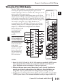
Wiring the T1H-CTRIO Module . . . . . . . . . . . . . . . . . . . . . . . . . . . . . . . . . . . . . . . .2–29
T1H-CTRIO Output Field Wiring . . . . . . . . . . . . . . . . . . . . . . . . . . . . . . . . . . . . . . .2–30
T1H-CTRIO Input Field Wiring . . . . . . . . . . . . . . . . . . . . . . . . . . . . . . . . . . . . . . . .2–30
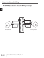
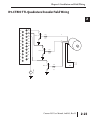
T1H-CTRIO Quadrature Encoder Wiring Example . . . . . . . . . . . . . . . . . . . . . . . . .2–31
T1H-CTRIO TTL Quadrature Encoder Field Wiring . . . . . . . . . . . . . . . . . . . . . . . . .2–32
ii
Counter I/O User Manual, 2nd Ed., Rev. D
Table of Contents
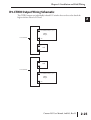
T1H-CTRIO TTL Input Wiring . . . . . . . . . . . . . . . . . . . . . . . . . . . . . . . . . . . . . . . . .2–33
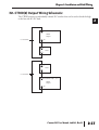
T1H-CTRIO Output Wiring Schematic . . . . . . . . . . . . . . . . . . . . . . . . . . . . . . . . . . .2–34
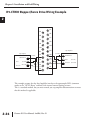
T1H-CTRIO Stepper/Servo Drive Wiring Example . . . . . . . . . . . . . . . . . . . . . . . . .2–35
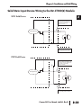
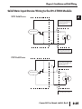
Solid State Input Device Wiring to T1H-CTRIO Module . . . . . . . . . . . . . . . . . . . . .2–36
Chapter 3: Introduction to CTRIO Workbench
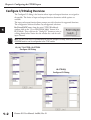
Configuring a CTRIO Module for Do-more CPUs . . . . . . . . . . . . . . . . . . . . . . . . . . .3–2
What is CTRIO Workbench? . . . . . . . . . . . . . . . . . . . . . . . . . . . . . . . . . . . . . . . . . . .3–2
Installing CTRIO Workbench . . . . . . . . . . . . . . . . . . . . . . . . . . . . . . . . . . . . . . . . . . .3–3
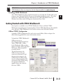
Getting Started with CTRIO Workbench . . . . . . . . . . . . . . . . . . . . . . . . . . . . . . . . .3–3
Offline CTRIO Configuration . . . . . . . . . . . . . . . . . . . . . . . . . . . . . . . . . . . . . . . . . . .3–3
Online CTRIO Configuration . . . . . . . . . . . . . . . . . . . . . . . . . . . . . . . . . . . . . . . . . . .3–4
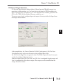
Successful On-line Connection . . . . . . . . . . . . . . . . . . . . . . . . . . . . . . . . . . . . . . . . .3–5
Module Modes of Operation . . . . . . . . . . . . . . . . . . . . . . . . . . . . . . . . . . . . . . . . . . .3–6
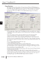
Program Mode - Configuring the CTRIO Module . . . . . . . . . . . . . . . . . . . . . . . . . .3–6
Run Mode - Start Processing I/O Pulses with the CTRIO Module . . . . . . . . . . . . . . .3–6
Chapter 4: Configuring the Inputs
Configure I/O Dialog Overview . . . . . . . . . . . . . . . . . . . . . . . . . . . . . . . . . . . . . . . . .4–2
Input Function Selections . . . . . . . . . . . . . . . . . . . . . . . . . . . . . . . . . . . . . . . . . . . . .4–5
Supported Functions . . . . . . . . . . . . . . . . . . . . . . . . . . . . . . . . . . . . . . . . . . . . . . . .4–5
Discrete Outputs Pre-Assigned to Input Functions . . . . . . . . . . . . . . . . . . . . . . . . . .4–5
Counter Function . . . . . . . . . . . . . . . . . . . . . . . . . . . . . . . . . . . . . . . . . . . . . . . . . . . .4–6
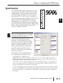
Quad Counter . . . . . . . . . . . . . . . . . . . . . . . . . . . . . . . . . . . . . . . . . . . . . . . . . . . . . .4–7
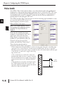
Pulse Catch . . . . . . . . . . . . . . . . . . . . . . . . . . . . . . . . . . . . . . . . . . . . . . . . . . . . . . . . .4–8
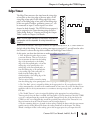
Edge Timer . . . . . . . . . . . . . . . . . . . . . . . . . . . . . . . . . . . . . . . . . . . . . . . . . . . . . . . . .4–9
Dual Edge Timer . . . . . . . . . . . . . . . . . . . . . . . . . . . . . . . . . . . . . . . . . . . . . . . . . . .4–10
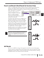
Reset 1 and Reset 2 (Hard Resets for Counters Only) . . . . . . . . . . . . . . . . . . . . . .4–11
Soft Resets . . . . . . . . . . . . . . . . . . . . . . . . . . . . . . . . . . . . . . . . . . . . . . . . . . . . . . . .4–11
Capture 1 . . . . . . . . . . . . . . . . . . . . . . . . . . . . . . . . . . . . . . . . . . . . . . . . . . . . . . . . .4–12
Inhibit 1 . . . . . . . . . . . . . . . . . . . . . . . . . . . . . . . . . . . . . . . . . . . . . . . . . . . . . . . . . .4–12
Introduction to the Scaling Wizard . . . . . . . . . . . . . . . . . . . . . . . . . . . . . . . . . . . . .4–13
Counter I/O User Manual, 2nd Ed., Rev. D
iii
Table of Contents
Scaling Wizard Examples for Counter Functions . . . . . . . . . . . . . . . . . . . . . . . . . . .4–13
Position Scaling (Counter) . . . . . . . . . . . . . . . . . . . . . . . . . . . . . . . . . . . . . . . . . . .4–14
Rate Scaling (Counter) . . . . . . . . . . . . . . . . . . . . . . . . . . . . . . . . . . . . . . . . . . . . . .4–15
Using the Scaling Wizard with Timer Functions . . . . . . . . . . . . . . . . . . . . . . . . . . .4–16
Interval Scaling (Timer) . . . . . . . . . . . . . . . . . . . . . . . . . . . . . . . . . . . . . . . . . . . . . .4–16
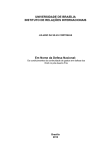
Chapter 5: Configuring the Outputs
Configure I/O Dialog Overview . . . . . . . . . . . . . . . . . . . . . . . . . . . . . . . . . . . . . . . . .5–2
Output Function Selections . . . . . . . . . . . . . . . . . . . . . . . . . . . . . . . . . . . . . . . . . . . .5–5
Supported Functions . . . . . . . . . . . . . . . . . . . . . . . . . . . . . . . . . . . . . . . . . . . . . . . .5–5
CTRIO Memory Usage: Pulse Profiles and Preset Tables . . . . . . . . . . . . . . . . . . . . . .5–5
Raw Output . . . . . . . . . . . . . . . . . . . . . . . . . . . . . . . . . . . . . . . . . . . . . . . . . . . . . . . .5–6
Discrete Outputs . . . . . . . . . . . . . . . . . . . . . . . . . . . . . . . . . . . . . . . . . . . . . . . . . . . .5–7
Creating and Using the Programmable Limit Switch (CTRIO2 only) . . . . . . . . . . . . .5–8
Creating and Using the Output Preset Tables . . . . . . . . . . . . . . . . . . . . . . . . . . . . .5–10
Using the Discrete Outputs in Level Mode . . . . . . . . . . . . . . . . . . . . . . . . . . . . . . .5–11
Pulse Outputs . . . . . . . . . . . . . . . . . . . . . . . . . . . . . . . . . . . . . . . . . . . . . . . . . . . . . .5–12
Creating Pulse Output Profile Tables . . . . . . . . . . . . . . . . . . . . . . . . . . . . . . . . . . . .5–12
Trapezoid Profile . . . . . . . . . . . . . . . . . . . . . . . . . . . . . . . . . . . . . . . . . . . . . . . . . . .5–13
Trapezoid Plus Profile . . . . . . . . . . . . . . . . . . . . . . . . . . . . . . . . . . . . . . . . . . . . . . .5–14
S-Curve Profile . . . . . . . . . . . . . . . . . . . . . . . . . . . . . . . . . . . . . . . . . . . . . . . . . . . . .5–15
Symmetrical S-Curve Profile . . . . . . . . . . . . . . . . . . . . . . . . . . . . . . . . . . . . . . . . . .5–16
Dynamic Positioning Profile . . . . . . . . . . . . . . . . . . . . . . . . . . . . . . . . . . . . . . . . . .5–17
Dynamic Positioning Plus Profile . . . . . . . . . . . . . . . . . . . . . . . . . . . . . . . . . . . . . . .5–18
Dynamic Velocity Profile . . . . . . . . . . . . . . . . . . . . . . . . . . . . . . . . . . . . . . . . . . . . .5–19
Home Search Profile . . . . . . . . . . . . . . . . . . . . . . . . . . . . . . . . . . . . . . . . . . . . . . . .5–20
Home Search Routines . . . . . . . . . . . . . . . . . . . . . . . . . . . . . . . . . . . . . . . . . . . . . .5–21
Trapezoid with Limits Profile . . . . . . . . . . . . . . . . . . . . . . . . . . . . . . . . . . . . . . . . . .5–22
Free Form Profile . . . . . . . . . . . . . . . . . . . . . . . . . . . . . . . . . . . . . . . . . . . . . . . . . . .5–25
Additional Pulse Profiles . . . . . . . . . . . . . . . . . . . . . . . . . . . . . . . . . . . . . . . . . . . . .5–26
Hx-CTRIO2 with Do-more . . . . . . . . . . . . . . . . . . . . . . . . . . . . . . . . . . . . . . . . . . .5–26
iv
Counter I/O User Manual, 2nd Ed., Rev. D
Table of Contents
Chapter 6: Program Control
Do-more and Program Control . . . . . . . . . . . . . . . . . . . . . . . . . . . . . . . . . . . . . . . . .6–2
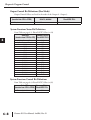
Input Memory Map for Data Transfers from CTRIO to DL CPUs . . . . . . . . . . . . . . .6–4
Input (n) Parameter Definitions . . . . . . . . . . . . . . . . . . . . . . . . . . . . . . . . . . . . . . . .6–4
Input Function Status Bit Definitions . . . . . . . . . . . . . . . . . . . . . . . . . . . . . . . . . . . . .6–5
Output Status Bit Definitions (for Preset Table Control) . . . . . . . . . . . . . . . . . . . . . .6–5
Output Status Bit Definitions (Pulse Output) . . . . . . . . . . . . . . . . . . . . . . . . . . . . . .6–5
Output Memory Map for Data Transfers from DL CPUs to CTRIO . . . . . . . . . . . . .6–6
Output (n) Parameter Definitions . . . . . . . . . . . . . . . . . . . . . . . . . . . . . . . . . . . . . . .6–6
Input Function Control Bit Definitions . . . . . . . . . . . . . . . . . . . . . . . . . . . . . . . . . . .6–7
Output Control Bit Definitions (for Preset Table Control) . . . . . . . . . . . . . . . . . . . . .6–7
Output Control Bit Definitions (Pulse Output) . . . . . . . . . . . . . . . . . . . . . . . . . . . . .6–7
Output Control Bit Definitions (Raw Mode) . . . . . . . . . . . . . . . . . . . . . . . . . . . . . . .6–8
System Functions Status Bit Definitions . . . . . . . . . . . . . . . . . . . . . . . . . . . . . . . . . . .6–8
System Functions Control Bit Definitions . . . . . . . . . . . . . . . . . . . . . . . . . . . . . . . . .6–8
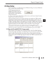
I/O Map Dialog . . . . . . . . . . . . . . . . . . . . . . . . . . . . . . . . . . . . . . . . . . . . . . . . . . . . .6–9
I/O Map with DirectLOGIC PLC (2 ranges mode) . . . . . . . . . . . . . . . . . . . . . . . . . . .6–9
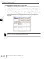
I/O Map with DirectLOGIC PLC (4 ranges mode) . . . . . . . . . . . . . . . . . . . . . . . . . .6–10
I/O Map with DirectLOGIC PLC with CTRIO in ERM/EBC Network . . . . . . . . . . . . .6–11
I/O Map with EBC/WinPLC . . . . . . . . . . . . . . . . . . . . . . . . . . . . . . . . . . . . . . . . . . .6–11
I/O Map with an H2-PBC or T1H-PBC Profibus DP Controller . . . . . . . . . . . . . . . . .6–12
Printing a Memory Map Report . . . . . . . . . . . . . . . . . . . . . . . . . . . . . . . . . . . . . . .6–13
Exporting to DirectSOFT . . . . . . . . . . . . . . . . . . . . . . . . . . . . . . . . . . . . . . . . . . . . .6–13
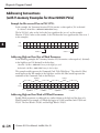
Addressing Conventions(with V-memory Examples for DirectLOGIC PLCs) . . . . .6–14
Example for Bit-accessed Data in PLC CPUs . . . . . . . . . . . . . . . . . . . . . . . . . . . . . .6–14
Addressing High and Low Byte of Word Parameters . . . . . . . . . . . . . . . . . . . . . . . .6–14
Addressing High and Low Word of DWord Parameters . . . . . . . . . . . . . . . . . . . . . .6–14
Input Function Status/Control Bits and Parameters . . . . . . . . . . . . . . . . . . . . . . .6–15
Input Function Status Bit Definitions . . . . . . . . . . . . . . . . . . . . . . . . . . . . . . . . . . . .6–15
Input Function Control Bit Definitions . . . . . . . . . . . . . . . . . . . . . . . . . . . . . . . . . .6–15
Input Function Status DWord Parameters . . . . . . . . . . . . . . . . . . . . . . . . . . . . . . . .6–15
Status Registers . . . . . . . . . . . . . . . . . . . . . . . . . . . . . . . . . . . . . . . . . . . . . . . . . . . .6–16
Control Registers . . . . . . . . . . . . . . . . . . . . . . . . . . . . . . . . . . . . . . . . . . . . . . . . . .6–16
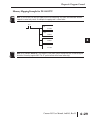
Memory Mapping Example for D2-240 CPU . . . . . . . . . . . . . . . . . . . . . . . . . . . . .6–17
Counter I/O User Manual, 2nd Ed., Rev. D
v
Table of Contents
Input Functions . . . . . . . . . . . . . . . . . . . . . . . . . . . . . . . . . . . . . . . . . . . . . . . . . . . .6–18
Counter & Quadrature Counter . . . . . . . . . . . . . . . . . . . . . . . . . . . . . . . . . . . . . . .6–18
Edge Timer and Dual Edge Timer . . . . . . . . . . . . . . . . . . . . . . . . . . . . . . . . . . . . . .6–19
Edge and Dual Edge Timer Timeout Function . . . . . . . . . . . . . . . . . . . . . . . . . . . . .6–20
Pulse Catch Input Function . . . . . . . . . . . . . . . . . . . . . . . . . . . . . . . . . . . . . . . . . . .6–21
Runtime Changes to CTRIO Configured Preset Tables (DL PLCs) . . . . . . . . . . . . .6–22
Entry Number for Edit Table Entry Commands . . . . . . . . . . . . . . . . . . . . . . . . . . . .6–23
Entry Type for Edit Table Entry Commands . . . . . . . . . . . . . . . . . . . . . . . . . . . . . . .6–23
Discrete Outputs Driven from a Scaled level . . . . . . . . . . . . . . . . . . . . . . . . . . . . . .6–24
Load Preset Table Flowchart . . . . . . . . . . . . . . . . . . . . . . . . . . . . . . . . . . . . . . . . . .6–25
Pulse Output Status/Control Bits and Command Codes (DL PLCs) . . . . . . . . . . .6–26
Output Status Bit Definitions (Pulse Output) . . . . . . . . . . . . . . . . . . . . . . . . . . . . .6-26
Output Control Bit Definitions (Pulse Output) . . . . . . . . . . . . . . . . . . . . . . . . . . . .6-26
Output Control (D) Words (Pulse Output) . . . . . . . . . . . . . . . . . . . . . . . . . . . . . .6-26
Command Code and Parameter Definitions . . . . . . . . . . . . . . . . . . . . . . . . . . . . . .6–27
Status and Control Bits/Registers . . . . . . . . . . . . . . . . . . . . . . . . . . . . . . . . . . . . . .6–28
Memory Mapping Example for D2-240 CPU . . . . . . . . . . . . . . . . . . . . . . . . . . . . .6–29
Pulse Output Profiles (DL PLCs) . . . . . . . . . . . . . . . . . . . . . . . . . . . . . . . . . . . . . . .6–30
Trapezoid, S-Curve, Symmetrical S-Curve, Home Search, Free Form Profiles . . . . . .6–31
Trapezoid, S-Curve, Symmetrical S-Curve, Home Search, Free Form Flowchart . . . .6–32
Running a Trapezoid, S-Curve, Symm. S-Curve, Home Search, Free Form Profile . .6–33
Dynamic Positioning and Dynamic Positioning Plus . . . . . . . . . . . . . . . . . . . . . . . .6–34
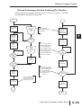
Dynamic Positioning and Dynamic Positioning Plus Flowchart . . . . . . . . . . . . . . . .6–35
Dynamic Positioning and Dynamic Positioning Plus using the CTRIO Y0 and Y1 . .6–36
Dynamic Velocity . . . . . . . . . . . . . . . . . . . . . . . . . . . . . . . . . . . . . . . . . . . . . . . . . .6–37
Dynamic Velocity using the CTRIO Y0 and Y1 . . . . . . . . . . . . . . . . . . . . . . . . . . . .6–37
Dynamic Velocity Mode Flowchart . . . . . . . . . . . . . . . . . . . . . . . . . . . . . . . . . . . . .6–38
Velocity Mode . . . . . . . . . . . . . . . . . . . . . . . . . . . . . . . . . . . . . . . . . . . . . . . . . . . .6–39
Velocity Mode control on CTRIO Y0 & Y1 . . . . . . . . . . . . . . . . . . . . . . . . . . . . . . .6–39
Velocity Mode Flowchart . . . . . . . . . . . . . . . . . . . . . . . . . . . . . . . . . . . . . . . . . . . .6–40
Run to Limit Mode . . . . . . . . . . . . . . . . . . . . . . . . . . . . . . . . . . . . . . . . . . . . . . . .6–41
Run to Limit Mode Flowchart . . . . . . . . . . . . . . . . . . . . . . . . . . . . . . . . . . . . . . . . .6–42
Run at Velocity on CTRIO Y0 & Y1 until Discrete Input Limit . . . . . . . . . . . . . . . . .6–43
Run to Position Mode . . . . . . . . . . . . . . . . . . . . . . . . . . . . . . . . . . . . . . . . . . . . . .6–44
Run to Position Mode Flowchart . . . . . . . . . . . . . . . . . . . . . . . . . . . . . . . . . . . . . . .6–45
vi
Counter I/O User Manual, 2nd Ed., Rev. D
Table of Contents
Run at Velocity on CTRIO until Input Function Value Position . . . . . . . . . . . . . . . . .6–46
System Functions . . . . . . . . . . . . . . . . . . . . . . . . . . . . . . . . . . . . . . . . . . . . . . . . . . .6–47
Reading All CTRIO’s Internal Registers Flowchart . . . . . . . . . . . . . . . . . . . . . . . . . .6–48
Writing to All CTRIO’s Internal Registers Flowchart . . . . . . . . . . . . . . . . . . . . . . . . .6–49
Writing to One CTRIO Internal Register Flowchart . . . . . . . . . . . . . . . . . . . . . . . . .6–50
Chapter 7: Using Monitor I/O
Do-more and Monitor CTRIO . . . . . . . . . . . . . . . . . . . . . . . . . . . . . . . . . . . . . . . . . .7–2
Using the Monitor I/O Dialog . . . . . . . . . . . . . . . . . . . . . . . . . . . . . . . . . . . . . . . . . .7–2
I/O Status & Input Functions . . . . . . . . . . . . . . . . . . . . . . . . . . . . . . . . . . . . . . . . . .7–3
Output Functions . . . . . . . . . . . . . . . . . . . . . . . . . . . . . . . . . . . . . . . . . . . . . . . . . . .7–4
System Functions . . . . . . . . . . . . . . . . . . . . . . . . . . . . . . . . . . . . . . . . . . . . . . . . . . .7–6
Monitor I/O Error Codes . . . . . . . . . . . . . . . . . . . . . . . . . . . . . . . . . . . . . . . . . . . . . .7–7
Chapter 8: DirectLOGIC Programming Examples
DirectLOGIC Programming Examples Overview . . . . . . . . . . . . . . . . . . . . . . . . . . .8-2
Load and Run a Pulse Profile . . . . . . . . . . . . . . . . . . . . . . . . . . . . . . . . . . . . . . . . . .8-3
Dynamic Positioning/Positioning Plus . . . . . . . . . . . . . . . . . . . . . . . . . . . . . . . . . . .8-4
Dynamic Velocity . . . . . . . . . . . . . . . . . . . . . . . . . . . . . . . . . . . . . . . . . . . . . . . . . . . .8-5
Velocity Mode . . . . . . . . . . . . . . . . . . . . . . . . . . . . . . . . . . . . . . . . . . . . . . . . . . . . . .8-6
Run to Limit Mode . . . . . . . . . . . . . . . . . . . . . . . . . . . . . . . . . . . . . . . . . . . . . . . . . . .8-7
Run to Position Mode . . . . . . . . . . . . . . . . . . . . . . . . . . . . . . . . . . . . . . . . . . . . . . . .8-8
Run to Position Mode with DirectSOFT IBox Instructions . . . . . . . . . . . . . . . . . . . .8-9
System Functions Examples Overview . . . . . . . . . . . . . . . . . . . . . . . . . . . . . . . . . .8-10
Simulating Retentive Counter . . . . . . . . . . . . . . . . . . . . . . . . . . . . . . . . . . . . . . . . .8-11
Reading CTRIO Internal Registers . . . . . . . . . . . . . . . . . . . . . . . . . . . . . . . . . . . . . .8-12
Chapter 9: Do-more Programming Examples
Do-more Programming Examples Overview . . . . . . . . . . . . . . . . . . . . . . . . . . . . . .9-2
Load and Run a Pulse Profile . . . . . . . . . . . . . . . . . . . . . . . . . . . . . . . . . . . . . . . . . .9-3
Dynamic Positioning/Positioning Plus . . . . . . . . . . . . . . . . . . . . . . . . . . . . . . . . . . .9-4
Dynamic Velocity . . . . . . . . . . . . . . . . . . . . . . . . . . . . . . . . . . . . . . . . . . . . . . . . . . . .9-5
Counter I/O User Manual, 2nd Ed., Rev. D
vii
Table of Contents
Velocity Mode . . . . . . . . . . . . . . . . . . . . . . . . . . . . . . . . . . . . . . . . . . . . . . . . . . . . . .9-6
Run to Limit Mode . . . . . . . . . . . . . . . . . . . . . . . . . . . . . . . . . . . . . . . . . . . . . . . . . . .9-7
Run to Position Mode . . . . . . . . . . . . . . . . . . . . . . . . . . . . . . . . . . . . . . . . . . . . . . . .9-8
System Functions Examples Overview . . . . . . . . . . . . . . . . . . . . . . . . . . . . . . . . . . .9-9
Simulating Retentive Counter . . . . . . . . . . . . . . . . . . . . . . . . . . . . . . . . . . . . . . . . . .9-9
Reading CTRIO Internal Registers . . . . . . . . . . . . . . . . . . . . . . . . . . . . . . . . . . . . . .9-10
viii
Counter I/O User Manual, 2nd Ed., Rev. D
INTRODUCTION TO THE
CTRIO & CTRIO2
MODULES
CHAPTER
1
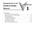
In This Chapter...
CTRIO and CTRIO2 Module Overview . . . . . . . . . . . . . . . . . . . . . . .1–2
Support Systems for the CTRIO Modules . . . . . . . . . . . . . . . . . . . . .1–4
CTRIO Specifications . . . . . . . . . . . . . . . . . . . . . . . . . . . . . . . . . . . .1–5
H0-CTRIO(2) LED Indicators . . . . . . . . . . . . . . . . . . . . . . . . . . . . . . .1–7
H2-CTRIO(2) LED Indicators . . . . . . . . . . . . . . . . . . . . . . . . . . . . . . .1–8
H4-CTRIO LED Indicators . . . . . . . . . . . . . . . . . . . . . . . . . . . . . . . . .1–9
T1H-CTRIO LED Indicators . . . . . . . . . . . . . . . . . . . . . . . . . . . . . . .1–10
CTRIO Module Workflow Diagram . . . . . . . . . . . . . . . . . . . . . . . . .1–11
Chapter 1: Introduction
CTRIO and CTRIO2 Module Overview
1
2
3
4
5
6
7
8
9
10
11
12
13
14
A
B
C
D
1–2
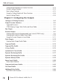
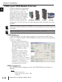
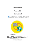
CTRIO(2) modules are programmable
high-speed discrete I/O modules that
accept signals from encoders and
discrete devices such as limit switches,
and generate precision output signals
for stepper control or other motionrelated discrete functions. CTRIO(2)
modules are coprocessors, having
H0-CTRIO(2) H2-CTRIO(2)
H4-CTRIO
T1H-CTRIO
their own scan time and their own
configurations. They have their own run mode and program mode, independent of the base
controller.
NOTE: For ease of documentation purposes, CTRIO will be used to designate all four CTRIO modules (H0CTRIO(2), H2-CTRIO(2), H4-CTRIO and T1H-CTRIO) when the functionality and/or description applies to all
four modules.
NOTE: The T1H-CTRIO is only supported by the T1H-EBC, T1H-EBC100 and T1H-PBC.
CTRIO Workbench
CTRIO Workbench is the utility used to configure the many functions available (listed
below) for a CTRIO(2) module. CTRIO Workbench is used in one of two ways, depending
on the base controller:
• Do-more: CTRIO Workbench is an
integrated utility of Do-more Designer.
The configuration becomes part of the
CPU project and is stored in the CPU.
The CPU will push the configuration to
the installed CTRIO(2) module as
appropriate.
• Any other base controller: CTRIO
Workbench is a separate utility that
communicates with a CTRIO(2)
module through the base controller to
configure the CTRIO(2). The
configuration is stored in the CTRIO(2)
and is a file that should also be stored on
your computer. Configuring the
CTRIO(2) is a process separate from
programming the base controller.
CTRIO Configuration
The CTRIO(2) module configuration created with CTRIO Workbench will define the
following:
Inputs:
1. Assign the input points
• Quadrature encoder with AB or ABZ
• Tachometer
Counter I/O User Manual, 2nd Ed., Rev. D
Chapter 1: Introduction
• Discrete (unassigned)
2. Functions applied to discrete inputs
• Simple discrete input
• Pulse catch (high-speed discrete input with programmable filter)
• Timing: edge timer (period), dual edge timer (time difference of two inputs)
• Reset counts (Z input from encoder)
• Capture counts (copy counts to a register)
• Inhibit counting
3. Scaling of timing functions or encoder inputs
Outputs:
1. Assign the output points
• Stepper control: Step/Direction or CW/CCW
• Discrete
2. Pulse profiles for stepper outputs to follow
• Trapezoid, S-curve, Symmetrical S-curve, Dynamic Position, Dynamic Velocity, Home
• Dynamic Position Plus, Trapezoid Plus, Trapezoid with Limits (CTRIO2 only and CTRIO
• Workbench v2.2.0 required)
3. Associate output functions with inputs
• Programmable Limit Switch or ‘PLS’ (CTRIO2 only and CTRIO Workbench v2.2.0
• required)
• Preset tables
CTRIO Functions
As mentioned above, the CTRIO(2) module supports five primary input functions: Counter,
Quad Counter, Pulse Catch, Edge Timer, and Dual Edge Timer.
Three secondary input functions are also supported. These functions, Reset, Capture, and
Inhibit, each modify the primary input functions in some way. Information is available about
each of the primary and secondary functions in chapter 4.
The CTRIO module supports three primary output functions: Pulse train output for
servo/stepper motor control, configurable for CW/CCW or step and direction, discrete
output functions assigned to Counter/Timer input functions, and raw output control directly
from the CPU interface program. Information is available about each of the output functions
in chapter 5.
NOTE: Before a CTRIO(2) will do anything, it must be configured, in run mode, and the memory must be
mapped. Mapping the memory is not required when used with a Do-more CPU.
Counter I/O User Manual, 2nd Ed., Rev. D
1
2
3
4
5
6
7
8
9
10
11
12
13
14
A
B
C
D
1–3
Chapter 1: Introduction
Typical Counter Applications:
• High-speed cut to length operations using encoder input
1
• Pick-and-place or indexing functions controlling a stepper drive
• Dynamic registration for web material control
2
• Accurate frequency counting for speed control with onboard scaling
• Positioning (e.g. flying punch)
3
• PLS - programmable limit switch functions for packaging, gluing or labeling
• Stepper motor drive control
4
• Valve control
• Rate monitoring for speed and/or flow
5
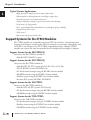
Systems for the CTRIO Modules
6 Support
The CTRIO modules are compatible with several CPU-slot interfaces. Consideration must
be given to the firmware versions of the CPU-slot interfaces to assure their compatibility with
7
the CTRIO. (See Chapter 2 for CPU/CTRIO compatibility listings). Multiple CTRIO
modules can reside in the same base provided that the backplane power budget is adequate.
8
Support Systems for the H0-CTRIO(2):
You can use the H0-CTRIO(2) module in:
9
• DirectLOGIC 05/06 PLC systems
Support Systems for the H2-CTRIO(2):
10
You can use the H2-CTRIO module in:
• DirectLOGIC 205 PLC systems (D2-240, D2-250-1 or D2-260)
11
• DL205 WinPLC systems (H2-WPLCx-xx)
• PC-based control strategies using the H2-EBC interface module
12
• Hx-ERM networks using the H2-EBC interface module
• Profibus systems using the H2-PBC slave interface module
13
• Do-more PLC systems (H2-DM1, H2-DM1E)
Support Systems for the H4-CTRIO:
14
You can use the H4-CTRIO module in:
• DirectLOGIC 405 PLC systems (D4-450 only)
A
• PC-based control strategies using the H4-EBC interface module
• Hx-ERM networks using the H4-EBC interface module
B
Support Systems for the T1H-CTRIO:
C
You can use the T1H-CTRIO module in:
• PC-based control strategies using the T1H-EBC interface module
D
• Profibus systems using the T1H-PBC slave interface module
• Hx-ERM networks using the T1H-EBC interface module
1–4
Counter I/O User Manual, 2nd Ed., Rev. D
Chapter 1: Introduction
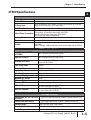
CTRIO Specifications
General
Module Type
Modules Per Base
Intelligent
I/O Points Used
None, I/O map directly in PLC memory (V-memory for DirectLOGIC PLCs and data
structures for Do-more PLCs) or PC control access
Limited only by power consumption
Field Wiring Connector
Standard removable terminal block
400 mA Max at +5V from Base Power Supply (H2, H4, T1H-CTRIO)
mA Max at +5V from Base Power Supply (H2-CTRIO2)
Internal Power Consumption 275
250 mA at +5V from Base Power Supply (H0-CTRIO(2))
(All I/O in ON State at Max Voltage/Current)
32°F to 140°F (0°C to 60°C), Humidity (non-condensing) 5% to 95%
Operating Environment
Manufacturer
Host Automation Products, LLC
Isolation
2500V I/O to Logic, 1000V among Input Channels and All Outputs (H0, H2, H4,
T1H-CTRIO)
1500V I/O to Logic, 1000V among Input Channels and All Outputs (H0, H2-CTRIO2)
CTRIO Input Specifications
Inputs (H2, H4, T1H-CTRIO,
H2-CTRIO2)
8 pts. sink/source 100 kHz Max (H2, H4, T1H-CTRIO)
8 pts. sink/source 250 kHz Max (H2-CTRIO2)
Inputs (H0-CTRIO(2))
4 pts. sink/source 100 kHz Max (H0-CTRIO)
4 pts. sink/source 250 kHz Max (H0-CTRIO2)
Minimum Pulse Width
5 µsec (H0, H2, H4, T1H-CTRIO)
0.5 µsec (H0, H2-CTRIO2)
Input Voltage Range
9-30 VDC
Maximum Voltage
Input Voltage Protection
Rated Input Current
Minimum ON Voltage
Maximum OFF Voltage
Minimum ON Current
Maximum OFF Current
30 VDC
OFF to ON Response
ON to OFF Response
Zener Clamped at 33 VDC
8 mA typical, 12 mA maximum
9.0 VDC
2.0 VDC
5.0 mA (9 VDC required to guarantee ON state)
2.0 mA
Less than 3 µsec (H0, H2, H4, T1H-CTRIO)
Less than 0.5 µsec (H0, H2-CTRIO2)
Less than 3 µsec (H0, H2, H4, T1H-CTRIO)
Less than 0.5 µsec (H0, H2-CTRIO2)
CTRIO Input Resources
Counter/Timer (H2, H4, T1H-CTRIO, 4, (2 per each 4 input channel group); supports 2 quadrature counters max.
H2-CTRIO2)
2, (2 per single 4 input channel); supports 1 quadrature counter max.
Counter/Timer (H0-CTRIO(2))
Resource Options
Timer Range/ Resolution
Counter Range
1X, 2X, or 4X Quadrature, Up or Down Counter, Edge Timer, Dual Edge Timer,
Input Pulse Catch, Reset, Inhibit, Capture
앧4.2 billion (32 bits); 1 µsec
1
2
3
4
5
6
7
8
9
10
11
12
13
14
A
B
C
D
앧2.1 billion (32 bits or 31 bits + sign bit)
Counter I/O User Manual, 2nd Ed., Rev. D
1–5
Chapter 1: Introduction
CTRIO Specifications
1
2
3
4
5
6
7
8
9
10
11
12
13
14
A
B
C
D
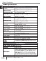
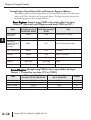
CTRIO Output Specifications
Outputs (H2, H4, T1H-CTRIO,
H2-CTRIO2)
Outputs (H0-CTRIO(2))
Pulse Output Control Range
Voltage range
Maximum voltage
Output clamp voltage
Maximum load current
Maximum load voltage
Maximum leakage current
Inrush current
4 pts, independently isolated, current sourcing or sinking
FET Outputs: open drain and source with floating gate drive
2 pts, isolated, either both current sourcing or both current sourcing
FET Outputs: open drain and source with floating gate drive
20 Hz to 25 kHz (H0, H2, H4, T1H-CTRIO)
20 Hz to 250 kHz (H0, H2-CTRIO2)
5VDC - 36VDC (H0, H2, H4, T1H-CTRIO, H2-CTRIO2)
36VDC (H0, H2, H4, T1H-CTRIO, H2-CTRIO2)
60VDC (H0, H2, H4, T1H-CTRIO)
1.0A (H0, H2, H4, T1H-CTRIO)
1.0A at 23°C, 0.5A at 60°C (H2-CTRIO2)
0.5A at 23°C, 0.33A at 60°C (H0-CTRIO2)
33VDC (H0-CTRIO2)
36VDC (H0, H2, H4, T1H-CTRIO, H2-CTRIO2)
100µA
1A for 10ms (H0-CTRIO2)
2A for 10ms (H2-CTRIO2)
5A for 20ms (H0, H2, H4, T1H-CTRIO)
OFF to ON response
less than 3µsec (H0, H2, H4, T1H-CTRIO, H0-CTRIO2)
less than 1µsec (H2-CTRIO2)
ON to OFF response
less than 3µsec (H0, H2, H4, T1H-CTRIO, H0-CTRIO2)
less than 1µsec (H2-CTRIO2)
울 0.3V (H0, H2, H4, T1H-CTRIO)
울 0.45V (H2-CTRIO2)
for loop power only, not required for internal module function*
15A max (H0, H2, H4, T1H-CTRIO)
Self resetting overcurrent protection (H0-CTRIO2)
Tjunction = 150°C
ON state V drop
External power supply
Overcurrent protection
Thermal shutdown
Overtemperature reset
Tjunction = 130°C
Duty cycle range
1% to 99% in 1% increments (default = 50%) (H0, H2, H4, T1H-CTRIO)
0.1% to 99.9% in 0.1% increments (H0, H2-CTRIO2)
Configurable Presets
a) single
b)multiple
a) each output can be assigned one preset, or
b) each output can be assigned one table of presets, one table can contain
max. 128 presets, max. predefined tables = 255
Pulse output / Discrete outputs
(H2, H4, T1H-CTRIO, H2-CTRIO2)
Pulse output / Discrete outputs
(H0-CTRIO(2))
Pulse outputs: 2 channels (2 outputs per each channel)
Discrete outputs: 4 pts.
CTRIO Output Resources
Pulse outputs: 1 channel (2 outputs per single channel)
Discrete outputs: 2 pts.
Resource Options
Pulse outputs: pulse/direction or cw/ccw; Profiles:Trapezoid, S-Curve,
Symmetrical S-Curve, Dynamic Positioning, Dynamic Velocity, Home Search,
Free Form, Dynamic Positioning Plus (CTRIO2),Trapezoid Plus (CTRIO2),
Trapezoid w/Limits (CTRIO2), Velocity Mode, Run to Limit Mode, Run to
Position Mode
Discrete outputs: configurable for set, reset, pulse on, pulse off, toggle,
reset count functions (assigned to respond to Timer/Count input functions).
Raw mode: Direct access to discrete outputs from user application program
Target Position Range
앧2.1 billion (32 bits or 31 bits + sign bit)
1–6
Counter I/O User Manual, 2nd Ed., Rev. D
Chapter 1: Introduction
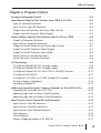
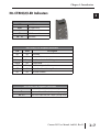
H0-CTRIO(2) LED Indicators
H0-CTRIO(2) LED Descriptions
Module OK
OK
User Program Error
ERR
Ch1 F1 Resource State
A
Ch1 F2 Resource State
B
Output Status
Y0 - Y1
H0-CTRIO(2) LED Diagnostic Definitions
ERR
Description
OK
ON
OFF
RUN Mode
ON
ON
Hardware Failure
Blinking
Blinking
Boot Mode - Used for Field OS Upgrades
Blinking
OFF
OFF
Blinking
Program Mode
OFF
ON
Module Error Due to Watchdog Timeout
OFF
OFF
No Power to Module
Module Self-diagnostic Failure
H0-CTRIO(2) LED Diagnostic Definitions
A
B
Y0 - Y1
Blinks when Channel 1 Function 1 is counting or timing
Blinks when Channel 1 Function 2 is counting or timing
Follow actual output state; ON = output is passing current
Counter I/O User Manual, 2nd Ed., Rev. D
1
2
3
4
5
6
7
8
9
10
11
12
13
14
A
B
C
D
1–7
Chapter 1: Introduction
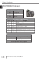
1 H2-CTRIO(2) LED Indicators
2
H2-CTRIO(2) LED Descriptions
OK
3
ER
1A
4
2A
0-3
5
H2-CTRIO(2) LED Diagnostic Definitions
6
OK
ER
Description
7
8
9
10
11
H2-CTRIO(2) LED Diagnostic Definitions
12
1A /2A
13
0-3
14
A
B
C
D
Module OK
User Program Error
Channel 1 Status
Channel 2 Status
Output Status
ON
OFF
RUN Mode
ON
ON
Blinking
Blinking
Blinking
OFF
OFF
Blinking
OFF
ON
Module Error Due to Watchdog Timeout
OFF
OFF
No Power to Module
Hardware Failure (H2-CTRIO)
Not Used (H2-CTRIO2)
Boot Mode - Used for Field OS Upgrades
Program Mode
Module Self-diagnostic Failure (Blinks may be coded by counts)
Blinking 7 times per second
Input is Configured as Counter and is Changing
Following State of Input
Input is not Configured as Counter
Follow actual output state; ON = output is passing current
1–8
Counter I/O User Manual, 2nd Ed., Rev. D
Chapter 1: Introduction
H4-CTRIO LED Indicators
H4-CTRIO LED Descriptions
Module OK
OK
User Program Error
ER
Ch1A - Ch1D Input Status
1A - 1D
Ch2A - Ch2D Input Status
2A - 2D
(Ch1) F1 - F2 Ch1 Resource State
(Ch2) F1 - F2 Ch2 Resource State
Output Status
Y0 - Y3
OK
ER
H4-CTRIO LED Diagnostic Definitions
Description
ON
OFF
Blinking
Blinking
Blinking
OFF
OFF
Blinking
OFF
ON
Module Error Due to Watchdog Timeout
OFF
No Power to Module
OFF
TB
RUN Mode
Boot Mode - Used for Field OS Upgrades
Program Mode
Module Self-diagnostic Failure
User Terminal Block is not Properly Installed
H4-CTRIO LED Diagnostic Definition
1A - 1D
2A - 2D
(Ch1) F1
(Ch1) F2
(Ch2) F1
(Ch2) F2
Y0 - Y3
Follow actual input state / Ch1
Follow actual input state / Ch2
blinks when Channel 1 Function 1 is counting or timing
blinks when Channel 1 Function 2 is counting or timing
blinks when Channel 2 Function 1 is counting or timing
blinks when Channel 2 Function 2 is counting or timing
Follow actual output state; ON = output is passing current
NOTE: Due to the multiplexed design of the DL405 LED matrix, OFF state LEDs may appear to blink ON
slightly. This is to be expected and does not necessarily indicate a transient condition of the function
corresponding to the LED.
Counter I/O User Manual, 2nd Ed., Rev. D
1
2
3
4
5
6
7
8
9
10
11
12
13
14
A
B
C
D
1–9
Chapter 1: Introduction
1 T1H-CTRIO LED Indicators
T1H-CTRIO LED Descriptions
2
OK
ER
3
CH1
CH2
4
1A - 1D
2A - 2D
5
Y0 - Y3
6
7
T1H-CTRIO LED Diagnostic Definitions
OK
ER
Description
8
9
10
11
12
T1H-CTRIO LED Diagnostic Definitions
13
CH1
CH2
14
Y0 - Y3
A
B
C
D
Module OK
User Program Error
Channel 1 Status
Channel 2 Status
Channel 1 A-D Input Status
Channel 2 A-D Input Status
Output Status
ON
OFF
RUN Mode
ON
ON
Hardware Failure
Blinking
Blinking
Blinking
OFF
OFF
Blinking
OFF
ON
Module Error Due to Watchdog Timeout
OFF
OFF
No Power to Module
Boot Mode - Used for Field OS Upgrades
Program Mode
Module Self-diagnostic Failure
Blinks when Channel 1 Function 1 is counting or timing
Blinks when Channel 2 Function 1 is counting or timing
Follow actual output state; ON = output is passing current
1–10
Counter I/O User Manual, 2nd Ed., Rev. D
Chapter 1: Introduction
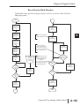
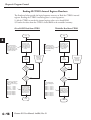
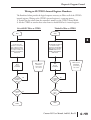
CTRIO Module Workflow Diagram
The following workflow diagrams show the steps needed, with their associated chapters in
this manual, to install a CTRIO module into your system.
DirectLOGIC, WinPLC or EBC
Do-more
Counter I/O User Manual, 2nd Ed., Rev. D
1
2
3
4
5
6
7
8
9
10
11
12
13
14
A
B
C
D
1–11
Chapter 1: Introduction
1 Notes:
2
3
4
5
6
7
8
9
10
11
12
13
14
A
B
C
D
1–12
Counter I/O User Manual, 2nd Ed., Rev. D
INSTALLATION AND
FIELD WIRING
In This Chapter...
CHAPTER
22
Installing the H0-CTRIO(2) Module . . . . . . . . . . . . . . . . . . . . . . . . . . . . . . . . . . . . . . . . . . .2–2
Setting the H0-CTRIO(2) Jumpers . . . . . . . . . . . . . . . . . . . . . . . . . . . . . . . . . . . . . . . . . . . .2–3
Wiring the H0-CTRIO(2) Module . . . . . . . . . . . . . . . . . . . . . . . . . . . . . . . . . . . . . . . . . . . . .2–4
H0-CTRIO(2) Quadrature Encoder Wiring Example . . . . . . . . . . . . . . . . . . . . . . . . . . . . . . . .2–5
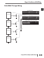
H0-CTRIO(2) TTL Quadrature Encoder Field Wiring Example . . . . . . . . . . . . . . . . . . . . . . . .2–6
H0-CTRIO(2) TTL Input Wiring Example . . . . . . . . . . . . . . . . . . . . . . . . . . . . . . . . . . . . . . . .2–7
H0-CTRIO(2) Output Wiring Schematic . . . . . . . . . . . . . . . . . . . . . . . . . . . . . . . . . . . . . . . .2–8
H0-CTRIO(2) Stepper/Servo Drive Wiring Example . . . . . . . . . . . . . . . . . . . . . . . . . . . . . . . .2–9
Solid State Input Device Wiring to the H0-CTRIO(2) Module . . . . . . . . . . . . . . . . . . . . . . .2–10
Installing the H2-CTRIO(2) Module . . . . . . . . . . . . . . . . . . . . . . . . . . . . . . . . . . . . . . . . . .2–11
Setting the H2-CTRIO(2) Jumpers . . . . . . . . . . . . . . . . . . . . . . . . . . . . . . . . . . . . . . . . . . .2–12
Wiring the H2-CTRIO(2) Module . . . . . . . . . . . . . . . . . . . . . . . . . . . . . . . . . . . . . . . . . . . .2–13
H2-CTRIO(2) Quadrature Encoder Wiring Example . . . . . . . . . . . . . . . . . . . . . . . . . . . . . . .2–14
H2-CTRIO(2) TTL Quadrature Encoder Field Wiring Example . . . . . . . . . . . . . . . . . . . . . . .2–15
H2-CTRIO(2) TTL Input Wiring Example . . . . . . . . . . . . . . . . . . . . . . . . . . . . . . . . . . . . . . .2–16
H2-CTRIO(2) Output Wiring Schematic . . . . . . . . . . . . . . . . . . . . . . . . . . . . . . . . . . . . . . .2–17
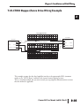
H2-CTRIO(2) Stepper/Servo Drive Wiring Example . . . . . . . . . . . . . . . . . . . . . . . . . . . . . . .2–18
Solid State Input Device Wiring to the H2-CTRIO(2) Module . . . . . . . . . . . . . . . . . . . . . . .2–19
Installing the H4-CTRIO Module . . . . . . . . . . . . . . . . . . . . . . . . . . . . . . . . . . . . . . . . . . . .2–20
Wiring the H4-CTRIO Module . . . . . . . . . . . . . . . . . . . . . . . . . . . . . . . . . . . . . . . . . . . . . .2–21
H4-CTRIO Quadrature Encoder Wiring Example . . . . . . . . . . . . . . . . . . . . . . . . . . . . . . . . .2–22
H4-CTRIO TTL Quadrature Encoder Field Wiring Example . . . . . . . . . . . . . . . . . . . . . . . . . .2–23
H4-CTRIO TTL Input Wiring Example . . . . . . . . . . . . . . . . . . . . . . . . . . . . . . . . . . . . . . . . .2–24
H4-CTRIO Output Wiring Schematic . . . . . . . . . . . . . . . . . . . . . . . . . . . . . . . . . . . . . . . . . .2–25
H4-CTRIO Stepper/Servo Drive Wiring Example . . . . . . . . . . . . . . . . . . . . . . . . . . . . . . . . .2–26
Solid State Input Device Wiring to the H4-CTRIO Module . . . . . . . . . . . . . . . . . . . . . . . . .2–27
Installing the T1H-CTRIO Module . . . . . . . . . . . . . . . . . . . . . . . . . . . . . . . . . . . . . . . . . . .2–28
Wiring the T1H-CTRIO Module . . . . . . . . . . . . . . . . . . . . . . . . . . . . . . . . . . . . . . . . . . . . .2–29
T1H-CTRIO Quadrature Encoder Wiring Example . . . . . . . . . . . . . . . . . . . . . . . . . . . . . . . .2–31
T1H-CTRIO TTL Quadrature Encoder Field Wiring Example . . . . . . . . . . . . . . . . . . . . . . . . .2–32
T1H-CTRIO TTL Input Wiring Example . . . . . . . . . . . . . . . . . . . . . . . . . . . . . . . . . . . . . . . .2–33
T1H-CTRIO Output Wiring Schematic . . . . . . . . . . . . . . . . . . . . . . . . . . . . . . . . . . . . . . . . .2–34
T1H-CTRIO Stepper/Servo Drive Wiring Example . . . . . . . . . . . . . . . . . . . . . . . . . . . . . . . .2–35
Solid State Input Device Wiring to the T1H-CTRIO Module . . . . . . . . . . . . . . . . . . . . . . . . .2–36
Chapter 2: Installation and Field Wiring
1
2
3
4
5
6
7
8
9
10
11
12
13
14
A
B
C
D
Installing the H0-CTRIO(2) Module
2-2
The H0-CTRIO(2) module is compatible with DirectLOGIC DL05 and DL06 PLCs.
Consideration must be given to the firmware versions of the PLCs to assure their
compatibility with the H0-CTRIO(2). (see chart below).
The H0-CTRIO(2) module plugs into any option card slot of any DL05 and DL06 PLC.
For installation instructions, refer to the:
• DL05 or DL06 User Manual (D0-USER-M or D0-06USER-M)
The first time you power-up the CTRIO module, you should see the OK LED blinking. The
blinking LED indicates that the module is in program mode.
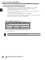
CPU and CTRIO Compatibility Chart
Firmware
DirectSOFT5
DL05
v. 4.60 or later
v. 4.0, Build 16 or later
DL06
v. 1.40 or later
v. 4.0, Build 16 or later
PLC CPU
H0-CTRIO(2)
Updated firmware versions can be downloaded from our web site at
www.automationdirect.com
NOTE: CTRIO Workbench Version 2.2.0 is required for the H0-CTRIO2.
Counter I/O User Manual, 2nd Ed., Rev. D
Chapter 2: Installation and Field Wiring
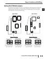
Setting H0-CTRIO(2) Jumpers
The module’s internal jumpers must be set to the High Side Common position for high side
switching (sourcing) outputs or to the Low Side Common position for low side switching
(sinking) outputs. The sink/source jumper selection sets both outputs to the same option.
Source operation is the factory default setting.
H0-CTRIO
H0-CTRIO2
Jumper Selections
Sourcing Outputs
High Common position
for switching the high
side of a DC load.
Jumper Selections
Sinking Outputs
Low Common position
for switching the low
side of a DC load.
Sourcing Outputs
Sinking Outputs
High Common position
for switching the high
side of a DC load.
Low Common position
for switching the low
side of a DC load.
Counter I/O User Manual, 2nd Ed., Rev. D
1
2
3
4
5
6
7
8
9
10
11
12
13
14
A
B
C
D
2-3
Chapter 2: Installation and Field Wiring
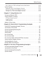
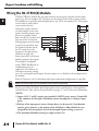
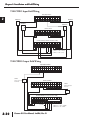
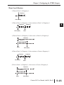
Wiring the H0-CTRIO(2) Module
+
L
L
–
+
2-4
The H0-CTRIO(2) module has one input channel, consisting of 4 optically isolated input
points (pts. A-D on common M). The inputs can be wired to either sink or source current.
The module has 2 optically isolated output points (pts. Y0-Y1 on common YC). The outputs
can be wired to either sink or
source current, but the
sink/source jumper selection
sets both outputs to the same
ERR
OK
option. Sourcing outputs must
Y0
IN
A
be wired so positive current
A
Y1
B
flows into the YC terminal and
B
CTR/TMR IN
9–30V 5–12mA
then out of the Yn terminal.
C
DC/Pulse Out
Sinking outputs must be wired
5–36V 1A
IN
D
so positive current flows into
A
+ M
Yn terminal and then out of
B
+ –
- +
YC
– +
C
the YC terminal (see the
9-30 VDC
5-36 VDC
Y0
D
diagram to the right and the
M
Y1
schematic on page 2-8).
YC
OUT – +
Source operation is the factory
Y0
default setting for the outputs.
5-36 VDC
Y1
OUT
The module is configured,
H0–CTRIO
using CTRIO Workbench, to
accommodate the user’s
application. The function of
each input (counting, timing,
reset, etc.) and output (pulse output, discrete output, etc.) is defined in the configuration of
the module.
Refer to Chapters 4 and 5 to determine what input and output configurations are possible.
-
1
2
3
4
5
6
7
8
9
10
11
12
13
14
A
B
C
D
NOTE: Field device wiring must be compatible with the module configuration.
See the notes below for further details about power source considerations, circuit polarities,
and field devices. Also, refer to the specifications on pages 1-5 and 1-6 for more information.
NOTES:
1. Inputs (A, B, C, and D) require user-provided 9-30VDC power sources. Terminal M
is the commons for the inputs. Maximum current consumption is 12mA per input
point.
2. Polarity of the input power sources (shown above) can be reversed. Consideration
must be given, however, to the polarity of the field device. Many field devices are
designed for only one polarity and can be damaged if power wiring is reversed.
3. The maximum allowable current per output circuit is 1A.
Counter I/O User Manual, 2nd Ed., Rev. D
Chapter 2: Installation and Field Wiring
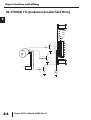
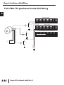
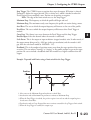
H0- CTRIO(2) Quadrature Encoder Wiring Example
OK
A
B
ERR
Y0
Y1
CTR/TMR IN
9–30V 5–12mA
DC/Pulse Out
5–36V 1A
IN
A
A
B
B
C
D
Z
M
YC
Gnd
+
-
Power
9-30VDC
Y0
Y1
OUT
H0–CTRIO
Sourcing Encoder
Counter I/O User Manual, 2nd Ed., Rev. D
1
2
3
4
5
6
7
8
9
10
11
12
13
14
A
B
C
D
2-5
Chapter 2: Installation and Field Wiring
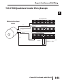
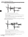
H0-CTRIO(2) TTL Quadrature Encoder Field Wiring
2-6
OK
A
B
ERR
Y0
Y1
CTR/TMR IN
9–30V 5–12mA
DC/Pulse Out
5–36V 1A
IN
A
C
10K
A
E
B
0.1W
10%
B
B
C
HFE > 100
D
M
E
YC
Z
Y0
Y1
C
10K
OUT
B
0.1W
10%
HFE > 100
H0–CTRIO
E
Power
+
-
C
Gnd
10K
0.1W
10%
B
HFE > 100
E
Counter I/O User Manual, 2nd Ed., Rev. D
9 - 30VDC
5VDC
1
2
3
4
5
6
7
8
9
10
11
12
13
14
A
B
C
D
+
-
Chapter 2: Installation and Field Wiring
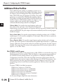
H0- CTRIO(2) TTL Input Wiring
OK
A
B
ERR
Y0
Y1
CTR/TMR IN
9–30V 5–12mA
DC/Pulse Out
5–36V 1A
IN
NPN
General Purpose Transistor
A
C
TTL Device
10K
B
C
B
D
HFE > 100
0.1W
10%
M
E
YC
Y0
Y1
OUT
H0–CTRIO
C
10K
B
0.1W
10%
HFE > 100
E
+
-
9 - 30VDC
TTL Device
C
TTL Device
10K
B
HFE > 100
0.1W
10%
E
C
TTL Device
10K
0.1W
10%
B
HFE > 100
E
Counter I/O User Manual, 2nd Ed., Rev. D
1
2
3
4
5
6
7
8
9
10
11
12
13
14
A
B
C
D
2-7
Chapter 2: Installation and Field Wiring
1
2
3
4
5
6
7
8
9
10
11
12
13
14
A
B
C
D
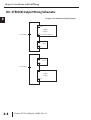
H0- CTRIO(2) Output Wiring Schematic
2-8
See page 2-3 for locating and setting the jumpers
YC
CTRIO
Output
+5 to 36VDC
Yn (where n=0 or 1)
+
Load
-
+
Load
+5 to 36VDC
Yn (where n=0 or 1)
CTRIO
Output
YC
Counter I/O User Manual, 2nd Ed., Rev. D
Chapter 2: Installation and Field Wiring
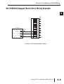
H0-CTRIO(2) Stepper/Servo Drive Wiring Example
IN
A
B
C
D
Step Amplifier
5-36VDC
OPTO Power
+ -
M
YC
(or CW)
Y0
Direction (or CCW)
Y1
Pulse
OUT
See page 2-3 for locating and setting the jumpers
Counter I/O User Manual, 2nd Ed., Rev. D
1
2
3
4
5
6
7
8
9
10
11
12
13
14
A
B
C
D
2-9
Chapter 2: Installation and Field Wiring
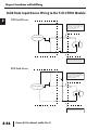
Solid State Input Device Wiring to the H0-CTRIO(2) Module
2-10
NPN Field Device
This drawing illustrates wiring that is
typical for Channel 1 terminals 1A, 1B,
1C, and 1D. The same circuitry is also
present at the corresponding
Channel 2 terminals.
1A
Sensing Circuit
24VDC
- +
1M
The same circuitry is present at the
corresponding Channel 2 terminal.
PNP Field Device
24VDC
1
2
3
4
5
6
7
8
9
10
11
12
13
14
A
B
C
D
Sensing Circuit
This drawing illustrates wiring that is
typical for Channel 1 terminals 1A, 1B,
1C, and 1D. The same circuitry is also
present at the corresponding
Channel 2 terminals.
+
-
1A
1M
The same circuitry is present at the
corresponding Channel 2 terminal.
Counter I/O User Manual, 2nd Ed., Rev. D
Chapter 2: Installation and Field Wiring
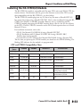
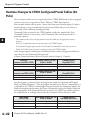
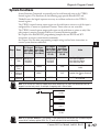
Installing the H2-CTRIO(2) Module
The H2-CTRIO(2) module is compatible with Do-more CPUs and several DL205 CPU-slot
interface devices. Consideration must be given to the firmware version of the CPU to assure
their compatibility with the H2-CTRIO(2). (see chart below).
The H2-CTRIO(2) module plugs into any I/O slot of any Do-more or DirectLOGIC 205
base except slot 0 when using a DirectLOGIC PLC. Slot 0 is also not allowed if using the H2CTRIO and a WinPLC or H2-PBC controller. However, slot 0 is available for the H2CTRIO(2) module when using the H2-EBC interface devices (Slot 0 is the I/O slot adjacent
to the CPU). The H2-CTRIO(2) cannot be used in DL205 local expansion bases or in Serial
Remote I/O bases.
For installation instructions, refer to the:
• DL205 User Manual (D2-USER-M) if using a DirectLOGIC PLC
• DL205 Installation and I/O Manual (D2-INST-M) if using a WinPLC, EBC,
• Profibus slave interface module
• Do-more H2 series PLC Harware User Manual (H2-DM-M) if using a Do-more PLC
The first time you power-up the CTRIO module, you should see the OK LED blinking. The
blinking LED indicates that the module is in program mode.
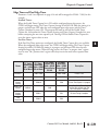
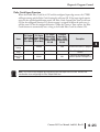
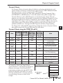
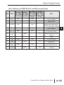
CPU and CTRIO Compatibility Chart
CPU-slot
Device
DirectSOFT5
Firmware
Hardware
Slot Restrictions
D2-240
v. 3.22 or later
-
v. 3.0C, Build 71 or later any I/O slot except 0
D2-250
v. 1.56 or later
-
v. 3.0C, Build 71 or later any I/O slot except 0
D2-250-1
v. 3.5 or later
-
v. 3.0C, Build 71 or later any I/O slot except 0
D2-260
v. 1.2 or later
-
v. 4.0 or later
any I/O slot except 0
-
xK or later
-
any I/O slot except 0
H2-EBC
v. 2.1.357 or later
-
-
prior to Rev 9A any I/O slot except 0;
Rev 9A or later any I/O slot
H2-PBC
-
-
-
prior to Rev 4A any I/O slot except 0;
Rev 4A or later any I/O slot
Do-more
Any
Any
N/A
H2-CTRIO(2)
H2-WinPLC
None
Counter I/O User Manual, 2nd Ed., Rev. D
1
2
3
4
5
6
7
8
9
10
11
12
13
14
A
B
C
D
2-11
Chapter 2: Installation and Field Wiring
Updated firmware versions can be downloaded from our web site at
www.automationdirect.com
1
Direct
2
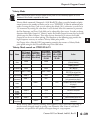
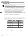
3 Setting H2-CTRIO(2) Jumpers
Jumpers are provided to connect input commons or outputs/output commons. Use of these
4
jumpers is not necessary to set up the CTRIO module. The jumpers are provided solely for
convenience in wiring.
5
6
7
8
9
10
11
12
13
14
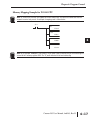
H2-CTRIO(2) Jumper Functions
H2-CTRIO
H2-CTRIO2
Function
A
B
C
D
SPECIAL NOTE: For applications requiring multiple CTRIO modules,
LOGIC CPUs, and dynamic
access (in ladder logic) to CTRIO data, we recommend using the D2-250-1 or D2-260 CPU. These CPUs
support Bit-of-Word addressing, 32 bit math instructions and have adequate memory for multiple CTRIO
applications.
H2-CTRIO2
H2-CTRIO
C3
H
C0
C3
H
C2
C3
H
C1
Y2
L
Y0
Y3
L
Y0
Y1
L
Y0
M2
2M
Y0
Y1
Y0
Y2
Y0
Y3
C0
C1
C0
C2
C0
C3
1M-2M
Install jumper to internally connect the input commons 1M and 2M
in order to reduce wiring if appropriate.
Y0-Y1
Y0-Y2
Y0-Y3
Install jumper(s) to internally connect Y0 to other Y terminals in
order to reduce wiring if appropriate. Connect wire at Y0.
C0-C1
C0-C2
C0-C3
Install jumper(s) to internally connect C0 to other C terminals in
order to reduce wiring if appropriate. Connect wire at C0.
C3-C0
C3-C1
C3-C2
2-12
1M
Install jumper(s) to internally connect C3 to other C terminals in
order to reduce wiring if appropriate. Connect wire at C3.
Counter I/O User Manual, 2nd Ed., Rev. D
M1
Chapter 2: Installation and Field Wiring
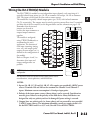
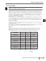
Wiring the H2-CTRIO(2) Module
The H2-CTRIO(2) module has two independent input channels, each consisting of 4
optically isolated input points (pts. 1A-1D on common 1M and pts. 2A-2D on common
2M). The inputs can be wired to either sink or source current.
The module has 4 optically isolated output points (pts. Y0-Y3 with isolated commons
C0-C3, respectively). The outputs must be wired so positive current flows into Cn terminal
and then out of the Yn terminal (see the diagram below and the schematic on page 2-19).
Remember that the internal
CTR
+24VDC
jumpers can be used to
IN
OUT PUTS
1A
connect the input commons or
0
O
K
2A
outputs/output commons
1
ER
1B
together.
C1
2
2B
3
C TR 2
1C
The module is configured,
H2--CTRI O
2C
using CTRIO Workbench, to
IN 9-30VDC 5-12mA
1D
OUT 5-36VDC
accommodate the user’s
1.0A max
2D
per point
application. The function of
1M
- +
each input (counting, timing,
1A
+ - 2M
2A
reset, etc.) and output (pulse
+ 1B
NC
2B
- +
output, discrete output, etc.) is
C2
1C
2C
L
C0
– +
defined in the configuration of
1D
2D
L
Y2
the module.
1M
2M
Y0
+ –
NC
Refer to Chapters 4 and 5 to
C3
C2
– +
L
C0
C
determine what input and
1
– +
Y2
L
Y0
Y3
output configurations are
C3
C1
Y1
possible.
+ –
Y3
-
+
–
+
–
–
+
Y1
+
NOTE: Field device wiring must be compatible with the module
configuration.
See the notes below for further details about power source
considerations, circuit polarities, and field devices.
NOTES:
1. Inputs (1A, 1B, 1C, 1D and 2A, 2B, 2C, 2D) require user-provided 9-30VDC power
sources. Terminals 1M and 2M are the commons for Channel 1 and Channel 2
inputs. Maximum current consumption is 12mA per input point.
2. Polarity of the input power sources (shown above) can be reversed. Consideration
must be given, however, to the polarity of the field device. Many field devices are
designed for only one polarity and can be damaged if power wiring is reversed.
3. Outputs have one polarity only (as shown above) and are powered by user-provided
5-36VDC power sources. The maximum allowable current per output circuit is 1A
for the H2-CTRIO and 1A at 23°C or 0.5A at 60°C for the H2-CTRIO2.
Counter I/O User Manual, 2nd Ed., Rev. D
1
2
3
4
5
6
7
8
9
10
11
12
13
14
A
B
C
D
2-13
Chapter 2: Installation and Field Wiring
H2- CTRIO(2) Quadrature Encoder Wiring Example
2-14
1A
2A
A
1B
A
B
2B
B
1C
+
-
9-30VDC
1D
Power
Gnd
Z
2C
Z
2D
1M
Power
9-30VDC
1
2
3
4
5
6
7
8
9
10
11
12
13
14
A
B
C
D
+
-
Gnd
2M
NC
C2
Sourcing Encoder
C0
Y2
Y0
C3
C1
Y3
Y1
Counter I/O User Manual, 2nd Ed., Rev. D
Sourcing Encoder
Chapter 2: Installation and Field Wiring
H2-CTRIO(2) TTL Quadrature Encoder Field Wiring
1A
2A
C
1B
2B
HFE > 100
1C
2C
10K
B
E
1D
A
0.1W
10%
B
Z
2D
1M
C
2M
NC
HFE > 100
C2
10K
B
0.1W
10%
C0
E
Y2
Y0
C3
C
Y3
Y1
9 - 30VDC
HFE > 100
E
B
10K
Gnd
+
-
5VDC
Power
C1
0.1W
10%
Counter I/O User Manual, 2nd Ed., Rev. D
1
2
3
4
5
6
7
8
9
10
11
12
13
14
A
B
C
D
2-15
+
Chapter 2: Installation and Field Wiring
H2-CTRIO(2) TTL Input Wiring
2-16
NPN
General Purpose Transistor
1A
2A
C
TTL Device
1B
2B
B
HFE > 100
1C
2C
0.1W
10%
E
1D
10K
2D
1M
2M
NC
C2
C0
C
Y2
Y0
TTL Device
B
HFE > 100
0.1W
10%
C3
C1
10K
E
Y3
9 - 30VDC
Y1
+
1
2
3
4
5
6
7
8
9
10
11
12
13
14
A
B
C
D
C
TTL Device
B
10K
HFE > 100
0.1W
10%
E
C
E
Counter I/O User Manual, 2nd Ed., Rev. D
TTL Device
B
HFE > 100
10K
0.1W
10%
Chapter 2: Installation and Field Wiring
H2- CTRIO(2) Output Wiring Schematic
The CTRIO outputs are individually isolated DC switches that can be used to break the high
or the low side of a DC load.
Cn (where n=0, 1, 2, 3)
CTRIO
Output
+5 to 36VDC
Yn
+
Load
-
+
Load
+5 to 36VDC
Cn (where n=0, 1, 2, 3)
CTRIO
Output
Yn
Counter I/O User Manual, 2nd Ed., Rev. D
1
2
3
4
5
6
7
8
9
10
11
12
13
14
A
B
C
D
2-17
Chapter 2: Installation and Field Wiring
1 H2-CTRIO(2) Stepper/Servo Drive Wiring Example
2
3
4
5
6
7
8
9
10
This example assumes that the Step Amplifier interface to be optocoupler LEDs (common
anodes at the “OPTO Power” terminal) with internal current limiting resistors.
11
This is a standard method, but you must consult you step amplifier documentation to ensure
that this method is applicable.
12
13
14
A
B
C
D
1A
2A
1B
2B
1C
2C
1D
2D
1M
2M
NC
Step Amplifier
5-36VDC
OPTO Power
Pulse
(or CW)
Direction (or CCW)
Step Amplifier
C2
C0
+ -
Y2
Y0
- +
OPTO Power
Pulse
(or CW)
C3
C1
Y3
Y1
2-18
5-36VDC
Counter I/O User Manual, 2nd Ed., Rev. D
Direction (or CCW)
Chapter 2: Installation and Field Wiring
Solid State Input Device Wiring to the H2-CTRIO(2) Module
NPN Field Device
This drawing illustrates wiring that is
typical for Channel 1 terminals 1A, 1B,
1C, and 1D. The same circuitry is also
present at the corresponding
Channel 2 terminals.
1A
Sensing Circuit
24VDC
- +
1M
The same circuitry is present at the
corresponding Channel 2 terminal.
24VDC
PNP Field Device
Sensing Circuit
This drawing illustrates wiring that is
typical for Channel 1 terminals 1A, 1B,
1C, and 1D. The same circuitry is also
present at the corresponding
Channel 2 terminals.
+
-
1A
1M
The same circuitry is present at the
corresponding Channel 2 terminal.
Counter I/O User Manual, 2nd Ed., Rev. D
1
2
3
4
5
6
7
8
9
10
11
12
13
14
A
B
C
D
2-19
Chapter 2: Installation and Field Wiring
Installing the H4-CTRIO
1
2
3
4
5
6
7
8
9
10
11
12
13
14
A
B
C
D
2-20
The H4-CTRIO module is compatible with two DL405 CPU-slot interface devices.
Consideration must be given to the firmware versions of the CPU-slot interfaces to assure
their compatibility with the H4-CTRIO. (see chart below).
The H4-CTRIO module plugs into any I/O slot of any DirectLOGIC 405 base. H4-EBCs
support the use of the H4-CTRIO in DL405 local expansion bases. The H4-CTRIO cannot
be used in Serial Remote I/O bases.
For installation instructions, refer to the:
• DL405 User Manual (D4-USER-M) if using a DirectLOGIC PLC
• DL405 Installation and I/O Manual (D4-INST-M) if using an H4-EBC interface
The first time you power-up the CTRIO module, you should see the OK LED blinking. The
blinking LED indicates that the module is in program mode.
CPU and CTRIO Compatibility Chart
Firmware
Hardware
DirectSOFT32
D4-450
April 2000 or earlier:
H8 (CISC) v. 2.00
SH (RISC) v. 1.500
May 2000 or later:
H8 (CISC) v. 2.00
SH (RISC) v. 2.500
-
v. 4.0, Build 16 or later
H4-EBC
2.1.328 or later
v. 4F or later
-
CPU-slot Device
Updated firmware versions can be downloaded from our web site at
www.automationdirect.com
Counter I/O User Manual, 2nd Ed., Rev. D
Chapter 2: Installation and Field Wiring
Wiring the H4-CTRIO Module
The H4-CTRIO module has two independent input channels, each
consisting of 4 optically isolated input points (pts.1A-1D on
common 1M and pts. 2A-2D on common 2M). The inputs can be
wired to either sink or source current.
The module has 4 optically isolated output points (pts.Y0-Y3 on
isolated commons C0-C3, respectively). The outputs must be wired
so that positive current flows into Cn terminal and then out of the
Yn terminal(see the diagram below and the schematic on page 2-25).
The module is configured, using CTRIO Workbench, to
accommodate the user’s application. The function of each input
(counting, timing, reset, etc.) and output (pulse output, discrete
output, etc.) is defined in the configuration of the module.
Refer to Chapters 4 and
5 to determine what
1A
input and output
2A
1B
configurations are
2B
possible.
COUNTER I/O
OK
2A
2B
2C
2D
F1
F2
Y2
Y3
9–30VDC
5–12mA
OUTPUT:
9–36VDC
1.0A Max
per point
1A
2A
1B
2B
1C
2C
1D
2D
+
+
+
1M
2M
NC
–
NC
+
L
–
+
C2
+
+
–
L
–
Y1
Y0
Y2
+
L
+
Y3
–
+
+
C1
+
C3
L
L
C3
C2
+
+
+
+
C1
C0
+
L
Y0
Y2
–
–
–
+
+
L
C0
L
2M
NC
+
NC
–
1M
–
+
Y1
Y3
–
See the notes below for
further details about
power source
considerations, circuit
polarities, and field
devices. Also, refer to
the specifications on
pages 1-5 and 1-6 for
more information.
2D
+
1D
+
F1
F2
Y0
Y1
INPUT:
2C
–
TB
H4–CTRIO
1C
NOTE: Field device wiring
must be compatible with
the module configuration.
ER
1A
1B
1C
1D
+
H4–CTRIO
NOTES:
1. Inputs (1A, 1B, 1C, 1D and 2A, 2B, 2C, 2D) require user-provided 9-30VDC power
sources. Terminals 1M and 2M are the commons for Channel 1 and Channel 2
inputs. Maximum current consumption is 12mA per input point.
2. Polarity of the input power sources (shown above) can be reversed. Consideration
must be given, however, to the polarity of the field device. Many field devices are
designed for only one polarity and can be damaged if power wiring is reversed.
3. Outputs have one polarity only (as shown above) and are powered by user-provided
5-36VDC power sources. The maximum allowable current per output circuit is 1A.
Counter I/O User Manual, 2nd Ed., Rev. D
1
2
3
4
5
6
7
8
9
10
11
12
13
14
A
B
C
D
2-21
Chapter 2: Installation and Field Wiring
1 H4-CTRIO Quadrature Encoder Wiring Example
2
3
4
5
6
7
8
+
9
10
11
12
13
14
A
B
C
D
1A
2A
A
1B
A
2B
B
1C
B
2C
1D
Z
2D
Z
1M
NC
NC
C0
9-30VDC
+
-
Power
9-30VDC
2M
Gnd
Gnd
Power
C2
Y0
Y2
C1
Sourcing Encoder
C3
Y1
Y3
2-22
Counter I/O User Manual, 2nd Ed., Rev. D
Sourcing Encoder
Chapter 2: Installation and Field Wiring
H4-CTRIO TTL Quadrature Encoder Field Wiring
1A
2A
1B
C
1C
HFE > 100
2B
10K
B
2C
0.1W
10%
1D
E
2D
A
B
1M
Z
2M
NC
NC
C
C0
C2
HFE > 100
10K
B
Y0
0.1W
10%
Y2
C1
E
C3
Y1
Y3
9 - 30VDC
HFE > 100
E
B
10K
Gnd
+
-
5VDC
Power
C
0.1W
10%
Counter I/O User Manual, 2nd Ed., Rev. D
1
2
3
4
5
6
7
8
9
10
11
12
13
14
A
B
C
D
2-23
+
Chapter 2: Installation and Field Wiring
1 H4-CTRIO TTL Input Wiring
2
3
4
5
6
7
8
9
10
11
12
13
14
A
B
C
D
NPN
General Purpose Transistor
1A
2A
C
TTL Device
1B
2B
B
HFE > 100
1C
0.1W
10%
2C
E
1D
10K
2D
1M
2M
NC
NC
C0
C2
C
TTL Device
Y0
Y2
B
HFE > 100
C1
C3
10K
0.1W
10%
E
Y1
+
9 - 30VDC
Y3
C
TTL Device
B
10K
HFE > 100
C
TTL Device
B
HFE > 100
2-24
0.1W
10%
E
E
Counter I/O User Manual, 2nd Ed., Rev. D
10K
0.1W
10%
Chapter 2: Installation and Field Wiring
H4-CTRIO Output Wiring Schematic
The CTRIO outputs are individually isolated DC switches that can be used to break the
high or the low side of a DC load.
Cn (where n=0, 1, 2, 3)
CTRIO
Output
+5 to 36VDC
Yn
+
Load
-
+
Load
+5 to 36VDC
Cn (where n=0, 1, 2, 3)
CTRIO
Output
Yn
Counter I/O User Manual, 2nd Ed., Rev. D
1
2
3
4
5
6
7
8
9
10
11
12
13
14
A
B
C
D
2-25
Chapter 2: Installation and Field Wiring
1
2
3
4
5
6
7
8
9
10
11
12
13
14
A
B
C
D
H4-CTRIO Stepper/Servo Drive Wiring Example
2-26
1A
2A
1B
2B
1C
2C
1D
2D
1M
2M
NC
Step Amplifier
5-36VDC
OPTO Power
Pulse
+ -
C2
C0
5-36VDC
- +
Y0
Y2
(or CW)
Direction (or CCW)
Step Amplifier
NC
C1
C3
OPTO Power
Pulse
(or CW)
Direction (or CCW)
Y1
Y3
This example assumes that the Step Amplifier interface to be optocoupler LEDs (common
anodes at the “OPTO Power” terminal) with internal current limiting resistors.
This is a standard method, but you must consult you step amplifier documentation to ensure
that this method is applicable.
Counter I/O User Manual, 2nd Ed., Rev. D
Chapter 2: Installation and Field Wiring
Solid State Input Device Wiring to the H4-CTRIO Module
NPN Field Device
This drawing illustrates wiring that is
typical for Channel 1 terminals 1A, 1B,
1C, and 1D. The same circuitry is also
present at the corresponding
Channel 2 terminals.
1A
Sensing Circuit
24VDC
- +
1M
The same circuitry is present at the
corresponding Channel 2 terminal.
24VDC
PNP Field Device
Sensing Circuit
This drawing illustrates wiring that is
typical for Channel 1 terminals 1A, 1B,
1C, and 1D. The same circuitry is also
present at the corresponding
Channel 2 terminals.
+
-
1A
1M
The same circuitry is present at the
corresponding Channel 2 terminal.
Counter I/O User Manual, 2nd Ed., Rev. D
1
2
3
4
5
6
7
8
9
10
11
12
13
14
A
B
C
D
2-27
Chapter 2: Installation and Field Wiring
1
2
3
4
5
6
7
8
9
10
11
12
13
14
A
B
C
D
Installing the T1H-CTRIO
2-28
The T1H-CTRIO module is compatible with several Terminator I/O Network interface
devices. Consideration must be given to the firmware versions of the Network interfaces to
assure their compatibility with the T1H-CTRIO. (see chart below).
The T1H-CTRIO module plugs into any valid I/O slot in a Terminator I/O system. The
T1H-CTRIO cannot be used in Serial Remote I/O bases (T1K-RSSS).
For installation instructions, refer to the:
• Terminator I/O Installation and I/O Manual (T1K-INST-M)
The first time you power-up the CTRIO module, you should see the OK LED blinking. The
blinking LED indicates that the module is in program mode.
CPU and CTRIO Compatibility Chart
CPU-slot Device*
Firmware
Hardware
T1H-EBC
v. 1.0.444 or later
v. 2I or later
T1K-PBC
v. 1.1.10 or later
v. 2D or later
Updated firmware versions can be downloaded from our web site at
www.automationdirect.com
NOTE: The T1H-CTRIO is only supported by the T1H-EBC, T1H-EBC100 and T1H-PBC.
Counter I/O User Manual, 2nd Ed., Rev. D
Chapter 2: Installation and Field Wiring
Wiring the T1H-CTRIO Module
The T1H-CTRIO module has two independent input channels, each consisting of 4 optically
isolated input points (pts. 1A-1D on common 1M and pts. 2A-2D on common 2M). The
inputs can be wired to either sink or source current.
The module has 4 optically isolated output points (pts. Y0-Y3 on isolated commons C0-C3,
respectively). The outputs must be wired so that positive current flows into Cn terminal and
then out of the Yn terminal. (see the diagram on the following page and the schematic on
page 2-34)
The module is configured, using CTRIO Workbench, to accommodate the user’s application.
The function of each input (counting, timing, reset, etc.) and output (pulse output, discrete
output, etc.) is defined in the configuration of the module.
Refer to Chapters 4 and 5 to determine what input and output configurations are possible.
NOTE: Field device wiring must be compatible with the module configuration.
See the notes below for further details about power source considerations, circuit polarities,
and field devices. Also, refer to the specifications on pages 1-5 and 1-6 for more information.
Apply the labels that come with the I/O module to the I/O
base terminals to properly identify the base terminal points.
Input / Output Channels
T1H–CTRIO
1A
1B 1C
1D
Y0 Y0
Y1
Y1
2A
2B
2C
2D
Y2
Y2
Y3
Y3
Channel Commons
1M
1M 1M
1M
C0 C0
C1
C1
2M 2M
2M
OK ERR CH1 CH2
1A 1B 1C 1D
2M
C2
C2
Y0 Y1
2A 2B 2C 2D
Y2 Y3
C3 C3
2
User Bus Terminals (no internal connection to CTRIO)
–––––––USER BUS 1–––––––
–––––––USER BUS 2–––––––
NOTES:
1. Inputs (1A, 1B, 1C, 1D and 2A, 2B, 2C, 2D) require user-provided 9-30VDC power sources.
Terminals 1M and 2M are the commons for Channel 1 and Channel 2 inputs. Maximum
current consumption is 12mA per input point.
2. Polarity of the input power sources can be reversed. Consideration must be given, however, to
the polarity of the field device. Many field devices are designed for only one polarity and can
be damaged if power wiring is reversed.
3. Outputs have one polarity only and are powered by user-provided 5-36VDC power sources.
The maximum allowable current per output circuit is 1A.
1
2
3
4
5
6
7
8
9
10
11
12
13
14
A
B
C
D
4. User Bus 1 and User Bus 2 are each an independent 8 wiring terminal bus. They can be used
for additional power rail connections.
Counter I/O User Manual, 2nd Ed., Rev. D
2-29
Chapter 2: Installation and Field Wiring
1
2
3
4
5
6
7
8
9
10
11
12
13
14
A
B
C
D
2-30
T1H-CTRIO Input Field Wiring
Input / Output Channels
1A
1B 1C
1D
Y0 Y0
Y1
Y1
2A
2B
2C
2D
Y2
Y2
Y3
Y3
PNP Device
NPN Device
Output
Output
_ +
NPN Device
_ +
PNP Device
Output
Output
_ +
_ +
Channel Commons
1M
1M 1M
C0 C0
1M
C1
C1
2M 2M
2M
2M
C2
C2
C3 C3
User Bus Terminals (no internal connection to CTRIO)
–––––––USER BUS 1–––––––
–––––––USER BUS 2–––––––
+
-
9-30VDC
USER BUS 1 = 1M = +24VDC
USER BUS 2 = 2M = 0VDC
T1H-CTRIO Output Field Wiring
Input / Output Channels
1A
CTRIO
Source To Load
From "Y0"
1B 1C
1D
Y0 Y0
Y1
Y1
2A
2B
2C
2D
Y2
Y2
Y3
Y3
2M
C2
C2
C3 C3
+
L
Channel Commons
1M
1M 1M
1M
C0 C0
C1
C1
2M 2M
2M
CTRIO
Sink From Load
into "C1"
L
+
User Bus Terminals (no internal connection to CTRIO)
–––––––USER BUS 1–––––––
+
-
5-36VDC
Counter I/O User Manual, 2nd Ed., Rev. D
–––––––USER BUS 2–––––––
USER BUS 1 = C0 = +24VDC
USER BUS 2 = Y1 = 0VDC
Chapter 2: Installation and Field Wiring
T1H-CTRIO Quadrature Encoder Wiring Example
Input / Output Channels
NPN Open Collector Output
Encoder
1A
1B 1C
1D
Y0 Y0
Y1
Y1
2A
2B
2C
2D
Y2
Y2
Y3
Y3
2M
C2
C2
C3 C3
A
Channel Commons
B
1M
1M 1M
1M
C0 C0
C1
C1
2M 2M
2M
Z
Power +
User Bus Terminals (no internal connection to CTRIO)
–––––––USER BUS 1–––––––
–––––––USER BUS 2–––––––
Gnd -
9-30VDC
+
-
USER BUS 1 = 1M = +24VDC
USER BUS 2 = 0VDC
Counter I/O User Manual, 2nd Ed., Rev. D
1
2
3
4
5
6
7
8
9
10
11
12
13
14
A
B
C
D
2-31
Chapter 2: Installation and Field Wiring
T1H-CTRIO TTL Quadrature Encoder Field Wiring
2-32
Input / Output Channels
1A
1B 1C
1D
Y0 Y0
Y1
Y1
2A
2B
2C
2D
Y2
Y2
Y3
Y3
2M
C2
C2
C3 C3
C
10K
A
E
B
0.1W
10%
B
Channel Commons
HFE > 100
E
1M
1M 1M
1M
C0 C0
C1
C1
2M 2M
2M
Z
User Bus Terminals (no internal connection to CTRIO)
C
10K
B
0.1W
10%
HFE > 100
–––––––USER BUS 1–––––––
E
Power
+
-
C
Gnd
10K
0.1W
10%
B
HFE > 100
E
9 - 30VDC
5VDC
1
2
3
4
5
6
7
8
9
10
11
12
13
14
A
B
C
D
Counter I/O User Manual, 2nd Ed., Rev. D
+
-
–––––––USER BUS 2–––––––
Chapter 2: Installation and Field Wiring
T1H-CTRIO TTL Input Wiring
Input / Output Channels
NPN
General Purpose Transistor
1A
1B 1C
1D
Y0 Y0
Y1
Y1
2A
2B
2C
2D
Y2
Y2
Y3
Y3
2M
C2
C2
C3 C3
C
TTL Device
10K
B
HFE > 100
0.1W
10%
Channel Commons
E
1M
1M 1M
1M
C0 C0
C1
C1
2M 2M
2M
User Bus Terminals (no internal connection to CTRIO)
C
TTL Device
–––––––USER BUS 1–––––––
B
9 - 30VDC
0.1W
10%
E
+
C
TTL Device
10K
–––––––USER BUS 2–––––––
HFE > 100
9 - 30VDC
10K
B
HFE > 100
0.1W
10%
E
C
TTL Device
10K
0.1W
10%
B
HFE > 100
E
Counter I/O User Manual, 2nd Ed., Rev. D
1
2
3
4
5
6
7
8
9
10
11
12
13
14
A
B
C
D
2-33
Chapter 2: Installation and Field Wiring
1
2
3
4
5
6
7
8
9
10
11
12
13
14
A
B
C
D
T1H-CTRIO Output Wiring Schematic
2-34
The CTRIO outputs are individually isolated DC switches that can be used to break the high
or the low side of a DC load.
Cn (where n=0, 1, 2, 3)
CTRIO
Output
+5 to 36VDC
Yn
+
Load
-
+
Load
+5 to 36VDC
Cn (where n=0, 1, 2, 3)
CTRIO
Output
Yn
Counter I/O User Manual, 2nd Ed., Rev. D
Chapter 2: Installation and Field Wiring
T1H-CTRIO Stepper/Servo Drive Wiring Example
Input / Output Channels
1A
1B 1C
1D
Y0 Y0
Y1
Y1
2A
2B
2C
2D
Y2
Y2
Y3
Y3
Step Amplifier
Step Amplifier
5-36VDC
- +
5-36VDC
OPTO Power
Pulse
Channel Commons
+ -
Pulse
(or CW)
1M
1M 1M
1M
C0 C0
C1
C1
2M 2M
2M
OPTO Power
2M
C2
C2
C3 C3
(or CW)
Direction (or CCW)
Direction (or CCW)
User Bus Terminals (no internal connection to CTRIO)
–––––––USER BUS 1–––––––
–––––––USER BUS 2–––––––
This example assumes that the Step Amplifier interface to be optocoupler LEDs (common
anodes at the “OPTO Power” terminal) with internal current limiting resistors.
This is a standard method, but you must consult you step amplifier documentation to ensure
that this method is applicable.
Counter I/O User Manual, 2nd Ed., Rev. D
1
2
3
4
5
6
7
8
9
10
11
12
13
14
A
B
C
D
2-35
Chapter 2: Installation and Field Wiring
Solid State Input Device Wiring to the T1H-CTRIO Module
2-36
NPN Field Device
This drawing illustrates wiring that is
typical for Channel 1 terminals 1A, 1B,
1C, and 1D. The same circuitry is also
present at the corresponding
Channel 2 terminals.
1A
Sensing Circuit
24VDC
- +
1M
The same circuitry is present at the
corresponding Channel 2 terminal.
PNP Field Device
24VDC
1
2
3
4
5
6
7
8
9
10
11
12
13
14
A
B
C
D
Sensing Circuit
This drawing illustrates wiring that is
typical for Channel 1 terminals 1A, 1B,
1C, and 1D. The same circuitry is also
present at the corresponding
Channel 2 terminals.
+
-
1A
1M
The same circuitry is present at the
corresponding Channel 2 terminal.
Counter I/O User Manual, 2nd Ed., Rev. D
INTRODUCTION TO
CTRIO WORKBENCH
CHAPTER
31
In This Chapter...
Configuring a CTRIO Module for Do-more CPUs . . . . . . . . . . . . . .3–2
What is CTRIO Workbench? . . . . . . . . . . . . . . . . . . . . . . . . . . . . . .3–2
Getting Started with CTRIO Workbench . . . . . . . . . . . . . . . . . . . . .3–3
Module Modes of Operation . . . . . . . . . . . . . . . . . . . . . . . . . . . . .3–6
Chapter 3: Introduction to CTRIO Workbench
Configuring a CTRIO Module for Do-more CPUs
1
With Do-more CPUs, the CTRIO Workbench software utility is not used. The functionality
of CTRIO Workbench is integrated into the Module Configuration for the CTRIO module.
2
To access it in Do-more Designer, open the System Configuration page, select Module
Configuration from the directory on the left, then find the CTRIO module you are
configuring in the list provided. Click the module to select it, then select Edit Config.
3
4
5
6
7
8
9
10
11
12
13
If you are using a Do-more CPU, the rest of this chapter does not pertain to you. See the
following chapters for information on configuring the inputs and outputs of your module
using Do-more Designer.
14
A What is CTRIO Workbench?
CTRIO Workbench is the software utility you will use to configure the CTRIO module’s
B
inputs and outputs. Workbench also lets you setup the CTRIO’s built-in scaling function
that will scale signals to desired engineering units, switch between the CTRIO’s Program
C
mode and Run mode, monitor I/O status and functions, and have diagnostic control of
module functions.
D
3–2
Counter I/O User Manual, 2nd Ed., Rev. D
Chapter 3: Introduction to CTRIO Workbench
NOTE: CTRIO Workbench Version 2.2.0 is required for the Hx-CTRIO2. Download the latest version of the
CTRIO Workbench utility at no charge from the Host Engineering Web site: www.hosteng.com.
Installing CTRIO Workbench
The CTRIO Workbench utility installs directly from its executable file. Double click on the
Setup.exe icon. The install shield will step you through the installation process. The utility
installs into C:\HAPTools directory. Find shortcuts to CTRIO Workbench from the
Windows Start Menu under All Programs>AutomationDirect Tools.
Getting Started with CTRIO Workbench
Several paths are available to start CTRIO Workbench. All users will find CTRIO
Workbench at Start>Programs>AutomationDirect Tools>CTRIO Workbench. DirectSOFT5
users will find CTRIO Workbench in the Utilities section of the DSLaunch Window.
Offline CTRIO Configuration
A complete CTRIO configuration file (.cwb) can be created Offline. (Refer to chapter 6 for
offline addressing guidelines for some of the interface devices.)
To launch the CTRIO Workbench 2
Offline version, go to
Start>Programs>AutomationDirect
Tools>CTRIO WB2 - Offline.
In the Workbench Offline window
shown to the right, click on the Select
PLC button. Select desired PLC
or interface device.
The only limitations in the
Offline version are that you
cannot access Monitor I/O and
that you cannot connect to the
CTRIO from the Offline utility.
Save the configuration file to disk
and connect to the CTRIO using
the appropriate Workbench
support version, then write the
file to the CTRIO.
Counter I/O User Manual, 2nd Ed., Rev. D
1
2
3
4
5
6
7
8
9
10
11
12
13
14
A
B
C
D
3–3
Chapter 3: Introduction to CTRIO Workbench
1
2
3
4
5
6
7
8
9
10
11
12
13
14
A
B
C
D
3–4
Online CTRIO Configuration
To configure the CTRIO module Online, a CTRIO must be installed in the PLC base or
Terminator I/O system, and the system power must be on. Your PC communicates with the
CTRIO module through the PLC or interface device port.
DirectSOFT5 Users
You will need to connect your PC to the CPU,
DCM or ECOM module. If you are linked to your
CPU through DirectSOFT5, CTRIO Workbench
will start via the existing link. If you are
“disconnected” from your PLC and start CTRIO
Workbench, you will be prompted to establish a link
to your CTRIO module.
DirectSOFT5 users will find CTRIO Workbench in the
DSLaunch Window’s Utilities section.
WinPLC, EBC and PLC>ERM>EBC Users
You will need to connect your PC to the RJ45 Ethernet port on
the WinPLC or EBC interface device directly or via hub,
switch,etc. (Connect to the ST-style fiber optic port on the HxEBC-F units.)
Access the WinPLC and EBC support version at
Start>Programs>AutomationDirect Tools>CTRIO Workbench
or in the DirectSOFT5 Launch Window Utilities menu. Then
select the appropriate Workbench version.
You will be prompted to establish an Ethernet link to
your CTRIO module.
NOTE: WinPLCs will need to be given an IP address before
connecting with Workbench.
EBCs will need to have an address selected by DIP Switch or
via NetEdit before connecting with Workbench.
Counter I/O User Manual, 2nd Ed., Rev. D
Chapter 3: Introduction to CTRIO Workbench
PBC, DEVNETS and MODBUS Users
You will need to connect your PC to the RJ12 serial port on
the PBC, DEVNETS or MODBUS interface device.
Access the various support versions at
Start>Programs>AutomationDirect Tools>CTRIO
Workbench or in the DirectSOFT5 Launch Window
Utilities menu. Then select the appropriate Workbench
version.
You will be prompted to establish a serial link to your
CTRIO module.
Select the PC serial port Workbench will use to
connect to the CTRIO module.
Successful On-line Connection
Once you are connected to your CTRIO module, you will enter the main window of
CTRIO Workbench. Here, you select the CTRIO module you wish to configure by clicking
on its slot number in the “Installed Modules” box. You will be able to enter Workbench’s
Configuration dialog, and after successfully configuring the module you will be able to toggle
the CTRIO module between Program Mode and Run Mode and enter the Monitor I/O
dialog.
Counter I/O User Manual, 2nd Ed., Rev. D
1
2
3
4
5
6
7
8
9
10
11
12
13
14
A
B
C
D
3–5
Chapter 3: Introduction to CTRIO Workbench
1
2
3
4
5
6
7
8
9
10
11
12
13
14
A
B
C
D
Module Modes of Operation
On the CTRIO Workbench main window, a single button toggles
between Run Mode and Program Mode. The Module Mode
indicator will tell you which mode your module is in. You can
make configuration changes in either Run Mode or Program
Mode, but to save your configuration to the module, you must
click “Write Module” which is only active in Program Mode.
In the lower left corner of the main Workbench dialog, is the
Config Status indicator. If the current configuration is different
from the CTRIO and different from any saved files, the indicator
will display the word “Changed.” If the current configuration has
been written to the module or a file, the message will read “Same
as Module,” “Same as File,” or “Same as Both.”
Program Mode - Configuring the CTRIO Module
After the configuration is created or changed in CTRIO Workbench, it must be “written” to
the CTRIO module. This is accomplished by returning to
the main CTRIO Workbench window and clicking on
“Write Module.”
If the configuration was created using Workbench Offline
version, you must connect your PC to the CTRIO module
through the CPU/controller and write the configuration to
the module.
NOTE: Entering program mode takes the CTRIO module offline. Input pulses are not read or
processed in Program mode, and all outputs are disabled. CPUs will hold last value in memory while
the CTRIO is in Program Mode.
Run Mode - Start Processing I/O Pulses with the CTRIO Module
Selecting Run Mode causes the CTRIO module to begin processing pulses based on the I/O
configuration you created.
In Run mode the CTRIO Workbench utility also allows you to monitor and verify the
proper operation of inputs and outputs. You can see the count change, reset, etc. using the
Monitor I/O dialog. Monitor I/O is very useful for debugging and commissioning of a new
system. See chapter 7 for information on Monitor I/O.
The CTRIO mode follows the CPU mode. If the CPU is placed in Run Mode, the CTRIO
module will also enter Run Mode. If the CPU is placed in STOP or PROGRAM Mode, the
CTRIO will enter Program Mode. The CTRIO also responds to mode changes made in
Workbench and can be placed in Run Mode while the CPU is in Stop or Program Mode.
The CTRIO module responds to the most recent change whether performed in Workbench
or from the CPU.
NOTE: The CTRIO module will not enter Run Mode if it does not have a valid configuration.
3–6
Counter I/O User Manual, 2nd Ed., Rev. D
CONFIGURING THE INPUTS
CHAPTER
4
In This Chapter...
Configure I/O Dialog Overview . . . . . . . . . . . . . . . . . . . . . . . . . . . .4–2
Input Function Selections . . . . . . . . . . . . . . . . . . . . . . . . . . . . . . . .4–5
Counter . . . . . . . . . . . . . . . . . . . . . . . . . . . . . . . . . . . . . . . . . . . . .4–6
Quadrature Counter . . . . . . . . . . . . . . . . . . . . . . . . . . . . . . . . . . . .4–7
Pulse Catch . . . . . . . . . . . . . . . . . . . . . . . . . . . . . . . . . . . . . . . . . . .4–8
Edge Timer . . . . . . . . . . . . . . . . . . . . . . . . . . . . . . . . . . . . . . . . . . .4–9
Dual Edge Timer . . . . . . . . . . . . . . . . . . . . . . . . . . . . . . . . . . . . . .4–10
Reset 1 and Reset 2 (Hard Resets for Counters Only) . . . . . . . . . . .4–11
Soft Resets . . . . . . . . . . . . . . . . . . . . . . . . . . . . . . . . . . . . . . . . . .4–11
Capture 1 . . . . . . . . . . . . . . . . . . . . . . . . . . . . . . . . . . . . . . . . . . .4–12
Inhibit 1 . . . . . . . . . . . . . . . . . . . . . . . . . . . . . . . . . . . . . . . . . . . .4–12
Introduction to the Scaling Wizard . . . . . . . . . . . . . . . . . . . . . . . .4–13
Chapter 4: Configuring the CTRIO Inputs
1
2
3
4
5
6
7
8
9
10
11
12
13
14
A
B
C
D
Configure I/O Dialog Overview
4–2
The Configure I/O dialog is the location where input and output functions are assigned to
the module. The choice of input and output functions determines which options are
available.
The input and output function boxes prompt you with selections for supported functions.
The configuration software disallows any unsupported selections.
For DirectLOGIC users, from the main CTRIO Workbench
window, click on the “Go to PROGRAM Mode” button (if in
RUN Mode). Then, click on the “Config I/O” button to arrive at
a dialog shown below. Notice that the window has a tab for each
input Channel.
NOTE: You don’t have to be in PROGRAM mode to enter the Configure I/O dialog, however you must be in
PROGRAM mode to save the configuration to the CTRIO module.
H2, H4, T1H-CTRIO, H2-CTRIO2
Configure I/O Dialog
H0-CTRIO(2)
Configure I/O Dialog
Counter I/O User Manual, 2nd Ed., Rev. D
Chapter 4: Configuring the CTRIO Inputs
For Do-more users, the Workbench options have been built into the Do-more Designer
software. The configuration dialog is found by first opening the System Configuration
window by selecting the “XY Configure” button in the main toolbar.
With the System Configuration page open, select the Module Configuration(s) page from the
lefthand column. On this page, highlight the desired CTRIO module and click Edit Config.
Counter I/O User Manual, 2nd Ed., Rev. D
1
2
3
4
5
6
7
8
9
10
11
12
13
14
A
B
C
D
4–3
Chapter 4: Configuring the CTRIO Inputs
1
2
3
4
5
6
7
8
9
10
11
12
13
14
A
B
C
D
4–4
Now the Edit CTRIO/CTRIO2 Configuration window should be open, click the “Configure
I/O...” button.
You should now have the Configure
I/O window open, similar to the one
shown here, with a tab for each input
Channel.
The input options are listed by
function. Four boxes labeled A, B, C,
and D correspond to the input
terminals on the face of the module
(1A-1D or 2A-2D; A-D for the H0CTRIO(2)).
The Output functions are listed as 0,
1, 2, and 3. These numbers
correspond to the markings beside the
module’s output terminals (Y0-Y3; Y0Y1 for the H0-CTRIO(2)).
Counter I/O User Manual, 2nd Ed., Rev. D
Chapter 4: Configuring the CTRIO Inputs
For DirectLOGIC users, be sure to write the changes to the module from Workbench when
the configuration is complete. For example, you might click on “Counter” in the “A” box,
then OK to return to the main Workbench window. Once you arrive back at the main
window, you must click “Write Module” to save your selection to the module. The module
will need to be in Program Mode to perform the Write Module operation. If you do not
perform the Write Module operation (or a Write File operation) your configuration will be
lost upon quitting Workbench. This applies to all changes to the module configuration.
For Do-more users, the “Write Module” button does not exist because the Module
Configuration dialog stores the CTRIO's configuration as a permanent part of the Do-more
controller's System Configuration.
Input Function Selections
Supported Functions
The input channels offer the same configuration options. The module supports five primary
input functions:
• Counter
• Quadrature Counter
• Pulse Catch
• Edge Timer
• Dual Edge Timer
Each of the primary functions uses one or two input terminals for making connections to
field devices (plus a common). Combinations of the listed functions are possible. The
configuration dialog disallows any unsupported configurations.
Three secondary input functions are also supported:
• Reset
• Capture
• Inhibit
Each secondary input modifies the primary input functions in some way and uses one input
terminal. (Limit Out 0 and Limit Out 2 input functions are only available for use when the
outputs are set to pulse output mode).
Discrete Outputs Pre-Assigned to Input Functions
CTRIO discrete outputs can be assigned to the Counter, Timer and Pulse Catch input
functions within the Configure I/O dialog. The outputs respond to presets assigned by the
user in the Preset Tables dialog. The presets are assigned based on the scaled value of an input,
or the raw value if it has no scaled value. The CTRIO’s four outputs can all be assigned to one
function, or they can be grouped within functions and within channels in any manner
selected by the user. See Chapter 5 for more information on using Preset Tables.
Counter I/O User Manual, 2nd Ed., Rev. D
1
2
3
4
5
6
7
8
9
10
11
12
13
14
A
B
C
D
4–5
Chapter 4: Configuring the CTRIO Inputs
1
2
3
4
5
6
7
8
9
10
11
12
13
14
A
B
C
D
Counter Function
4–6
The CTRIO module supports up or down counting using single-ended encoders (or other
single-ended pulse sources) as inputs. Encoders, proximity
A
sensors, etc., can be connected to input A and/or input B
on either channel or both channels. The C and D inputs
are available to modify the A and B inputs. The C and D
inputs can be used for Reset, Inhibit, or Capture. These
functions are explained later in this chapter. The CTRIO
discrete output(s) can be assigned to the Counter function
using the Preset Tables dialog. Refer to “Creating and Using
the Output Tables” section in Chapter 5 for details.
1A
2A
1B
2B
1C
2C
1D
2D
1M
2M
NC
C2
C0
Y2
NOTE: To insure proper operation, the field device wiring and the
configuration must be compatible. For wiring information see
Chapter 2.
Y0
C3
C1
Y3
Y1
The module’s four input terminals are represented by the A,
B, C, and D boxes on the left side of this dialog. If you are
wiring your counter input to terminal 1A, you will want to
select the Channel 1 tab near the top of this window and click “Counter” in box A.
At this point, you have four decisions to make regarding your input at 1A.
1. Select count up or count down. A button, in the Function 1 box, toggles between Up and Down
counting. Click the button labeled “Up” (or “Down”) to see the change to the opposite count
direction.
2. Each input pulse is counted, but you are free to
designate whether you want the count to register
on the rising edge of the pulse, the falling edge, or
both. The button with the graphical
representation of a pulse toggles between these
choices.
3. The Reset value is assigned by clicking and
typing a value in the data input field. This value is
for hardwired resets. When the hardwired reset is
activated, the count value returns to the reset
value.
4. The last remaining decision to be made is about
scaling. Clicking the button with the ruler symbol
starts the Scaling Wizard. We discuss the scaling
wizard later in this chapter. The Scaling Wizard is
intelligent in that it offers scaling options that are appropriate for your input selections.
Counter I/O User Manual, 2nd Ed., Rev. D
Chapter 4: Configuring the CTRIO Inputs
Quad Counter
The CTRIO module supports quadrature counting
using quadrature encoders as inputs. Connect your
encoder to input A and input B on either channel. A
second quadrature encoder can be connected to the
other channel. The C and D inputs are available to
control the quadrature input counting. The C and D
inputs can be used for Reset, Inhibit, or Capture.
These functions are explained later in this chapter.
The CTRIO discrete output(s) can be assigned to the
Quad Counter function using the Preset Tables dialog.
Refer to “Creating and Using the Output Tables”
section in Chapter 5 for details.
1A
A
2A
1B
B
2B
1C
2C
1D
2D
1M
2M
NC
C2
C0
Y2
Y0
C3
C1
Y3
Y1
NOTE: To insure proper operation, the field device
wiring and the configuration must be compatible.
For wiring information see Chapter 2.
Notice that the module’s four input
terminals are represented by the A, B, C,
and D boxes on the left side of this dialog.
If you are wiring your quadrature counter
inputs to terminal 1A and 1B, you will
need to select the Channel 1 tab near the
top of this window and click “Quad
Counter” in box A. Notice that input B is
now slaved to input A.
At this point, you have three decisions to
make regarding your quadrature input.
1. A multiplier can be applied to the
quadrature input to increase its resolution. Select “1x”, “2x”, or “4x.” [1X = pulses processed on
leading edge of input A, 2X = pulses are processed on both edges of input A, 4X = pulses processed
on both edges of input A and both edges of input B.]
2. The “Reset Value” is assigned by clicking in the data input field and typing in a value. When the
count is reset, using any of the reset methods, the count value returns to the Reset Value. The reset
options are described in more detail later in this chapter.
3. The last remaining decision to be made is about scaling. Clicking the button with the ruler symbol
starts the Scaling Wizard. The Scaling Wizard is intelligent in that it offers only those scaling options
that are appropriate for your input selections. We discuss the scaling wizard in greater detail later in
this chapter.
Counter I/O User Manual, 2nd Ed., Rev. D
1
2
3
4
5
6
7
8
9
10
11
12
13
14
A
B
C
D
4–7
Chapter 4: Configuring the CTRIO Inputs
1
2
3
4
5
6
7
8
9
10
11
12
13
14
A
B
C
D
Pulse Catch
4–8
The CTRIO “Pulse Catch” function allows a very short duration pulse to be qualified and
lengthened to a time period long enough to guarantee that it is seen by the CPU. CPU scans
necessarily vary with the length and complexity of the user’s program. A scan frequency of
several milliseconds, or more, is common. A pulse that lasts less than one millisecond, is
typically hard to catch during the CPU scan.
The CTRIO module’s Pulse Catch function sees the fast incoming signal and holds its status
in a status bit until the CPU can see it. A
discrete output(s) can also be tied to
follow the Pulse Catch input.
NOTE: To insure proper operation, the field
device wiring and the configuration must be
compatible. For wiring information see
Chapter 2.
Notice that the module’s four input
terminals are represented by the A, B, C,
and D boxes on the left side of this
dialog. If you are wiring your input to
terminal 1C, you will need to select the
Channel 1 tab near the top of this
window and click Pulse Catch in box C.
Three selections must be made in
conjunction with the Pulse Catch option.
1. First, a decision must be made whether to look for the rising edge of the pulse or the falling edge
of the pulse. This is a critical decision. Careful attention should be paid to the type of output the
field device generates. If the signal voltage is normally low, but a short duration pulse sends the signal
to the ON state, you will want to trigger off the rising
edge, and vice versa.
2. The second decision you will need to make is the
minimum pulse width you want to capture. Transients
below this width will not be recorded. Set this value by
typing the desired value in the “Minimum Width In”
field.
3. The final decision to be made is the length of pulse
the CTRIO module should send in response to the
input pulse. Make this setting by typing in the desired
value in the “Pulse Out Width” field.
1A
2A
1B
2B
1C
2C
1D
2D
1M
2M
NC
C2
C0
Y2
Y0
C3
C1
Y3
Y1
Counter I/O User Manual, 2nd Ed., Rev. D
n + 20.8
status bit
D
Chapter 4: Configuring the CTRIO Inputs
Edge Timer
The Edge Timer measures the time from the rising edge
of one pulse to the rising edge of the next pulse, or the
rising edge of one pulse to the falling edge of the same
pulse, or the falling edge of one pulse to the falling edge
of the next pulse. Encoders, proximity sensors, etc., can
be connected to input C and/or input D on either
channel or both channels. The CTRIO discrete output(s)
can be assigned to the Timer function using the Preset
Tables dialog. Refer to “Creating and Using the Output
Tables” section in Chapter 5 for details.
1A
2A
1B
2B
1C
C
2C
1D
2D
1M
2M
NC
C2
C0
Y2
Y0
C3
NOTE: To insure proper operation, the field device wiring and the
configuration must be compatible. For wiring information see
Chapter 2.
C1
Y3
Y1
Notice that the module’s four input terminals are represented by the A, B, C, and D boxes on
the left side of this dialog. If you are wiring your input to terminal 1C, you will need to select
the Channel 1 tab near the top of this window and click Edge Timer in box C.
At this point, you have four decisions to make regarding your input at 1C.
1. First, designate the pulse edges you want
to measure between. There are four choices.
You can measure the time from the leading
edge of the upward pulse to the leading
edge of the next upward pulse, or from the
trailing edge of an upward pulse to the
trailing edge of the next upward pulse, or
from the leading edge of an upward pulse
to the trailing edge of the same pulse, or,
finally, from the leading edge of a
downward pulse to the trailing edge of the
same downward pulse.
The last option could be restated as timing
from the trailing edge of an upward pulse to the rising edge of the next upward pulse.
2. The “Free Run” option is assigned by clicking in the appropriate box. If your application calls for
velocity measurements to be taken at the commencement of some event, do not use Free Run. If your
application calls for velocity measurement on a continuous (moving average) basis, you should use
Free Run.
3. The “Enable Timeout” option is assigned by clicking in the appropriate box and specifying a
Timeout period. Once the timer is enabled, the Timeout Bit is set if the time that it takes the CTRIO
to see the configured input edge exceeds the specified Timeout Period. Also, if the time before the
CTRIO sees the next configured edge exceeds the specified Timeout Period, the Timeout bit is set.
More information about the Timeout function can be found in chapter 6.
4. The last remaining decision to be made is about scaling. Clicking the button with the tape measure
symbol starts the Scaling Wizard. We discuss the scaling wizard later in this chapter. The Scaling
Wizard is intelligent in that it offers scaling options that are appropriate for your input selections.
Counter I/O User Manual, 2nd Ed., Rev. D
1
2
3
4
5
6
7
8
9
10
11
12
13
14
A
B
C
D
4–9
Chapter 4: Configuring the CTRIO Inputs
Timer
1 Dual Edge
The Dual Edge Timer is designed to measure from a pulse edge on one incoming signal to a
pulse edge on another incoming signal. The user selects whether to measure between rising
2
edges, falling edges, etc. The choices are summarized in the tables below. The CTRIO discrete
output(s) can be assigned to the Dual Edge Timer function using the Preset Tables dialog.
Refer to “Creating and Using the Output Tables” section in Chapter 5 for details.
3
Dual Edge Timer at Function 1
Dual Edge Timer at Function 2
4
5
6
7
NOTE: To insure proper operation, the field device wiring and the configuration must be compatible. For
wiring information see Chapter 2.
8
Notice that the module’s four input terminals are represented by the A, B, C, and D boxes on
the left side of this dialog. If you are wiring your inputs to terminals 1C and 1D, you will
9
need to select the Channel 1 tab near the top of this window and click Dual Edge Timer in
box C or D.
10
At this point, you have four decisions to make regarding your input at 1C or 1D.
1. First, designate the pulse edges you want to measure between.
11
2. The “Free Run” option is assigned by clicking in the appropriate box. If your application calls for
velocity measurements to be taken at the commencement of some event, do not use Free Run. If your
application calls for velocity measurement on a
12
continuous basis, you should use Free Run.
3. The “Enable Timeout” option is assigned by
13
clicking in the appropriate box and specifying a
Timeout period. Once the timer is enabled, the
Timeout Bit is set if the time that it takes the
14
CTRIO to see the configured l input edge exceeds
the specified Timeout Period. Also, if the time
before the CTRIO sees the next configured edge
A
exceeds the specified Timeout Period, the Timeout
bit is set. More information about the Timeout
function can be found in chapter 6.
B
4. The last remaining decision to be made is about
scaling. Clicking the button with the tape measure
C
symbol starts the Scaling Wizard. We discuss the
scaling wizard later in this chapter. The Scaling
Wizard is intelligent in that it offers scaling options
D
that are appropriate for your input selections.
4–10
Rising edge of C to rising edge of D
Rising edge of D to rising edge of C
Rising edge of C to falling edge of D
Rising edge of D to falling edge of C
Falling edge of C to rising edge of D
Falling edge of D to rising edge of C
Falling edge of C to falling edge of D
Falling edge of D to falling edge of C
Counter I/O User Manual, 2nd Ed., Rev. D
Chapter 4: Configuring the CTRIO Inputs
Reset 1 and Reset 2 (Hard Resets for Counters Only)
“Reset 1” is available only if you have selected a Counter or Quad Counter as the primary
function. For example, if you have chosen either counter function (single-ended or
quadrature) on terminal 1A, you will have an option of using terminal 1C for a hard reset
signal. Other options are available on
terminal 1D. Those options are
Capture and Inhibit (see next page).
Reset 2 is available if you have
selected to use terminal 1B for a
counter input. Reset 2 will reset the counter
connected to terminal 1B.
Two distinct types of hard resets are available. One is
an edge reset. The other is a level reset. The Edge
n-1
n
1
2
Reset sets the current count to zero on the specified
edge (rising or falling) of the reset pulse (see upper
example). The Level Reset resets the count to zero (as
long as the reset pulse is held high (or low depending
on configuration). When the reset pulse disappears,
Edge Reset
the count resumes (see lower example).
If the Reset options are not available in the Configure
I/O dialog, then you have selected input functions
that do not use the reset modifier.
1A
2A
1B
2B
1C
2C
1D
A
2D
1M
2M
NC
C2
C0
C
Y2
Y0
C3
C1
Y3
Y1
NOTE: Reset 1 and Reset 2 represent hard-wired inputs to
terminal C or D. An appropriate field device must be
connected to the designated terminal to perform the reset
function.
1A
2A
1B
2B
1C
n-1
n
1
A
2C
1D
2D
1M
2M
NC
C2
C0
C
Level Reset
Y2
Y0
C3
C1
Y3
Y1
Soft Resets
Soft resets are available by turning on the appropriate control bit in your control program
(Counters only) or by using the Reset Count function within a Discrete Output Preset Table
configuration (Counters/Timers). Counter control bit resets are always level resets, meaning
they hold the count at zero until the reset bit is turned off.
Counter I/O User Manual, 2nd Ed., Rev. D
1
2
3
4
5
6
7
8
9
10
11
12
13
14
A
B
C
D
4–11
Chapter 4: Configuring the CTRIO Inputs
Capture 1
1
“Capture 1” is available only if you have selected a
Counter or Quad Counter as the primary function. For
2
example, if you have chosen either counter function on
terminal 1A, you will have an option of using terminal
1D for a capture signal.
3
Capture 1 “snapshots” the current count into the 2nd
DWord register (Parameter 2). The Capture feature is
4
available with a single-ended Counter on input A or a
Quad Counter on inputs A and B.
5
NOTE: Capture 1 represents a hard-wired input to terminal D.
An appropriate field device must be connected to the
designated terminal to perform the capture function.
6
7
8 Inhibit 1
“Inhibit 1” is available only if you have selected a Counter or Quad Counter as the primary
9
function. For example, if you have chosen either
counter function on terminal 1A, you will have an
10
option of using terminal 1D for an inhibit signal.
The “Inhibit 1” signal prevents the CTRIO from
11
counting pulses. The Inhibit feature is available with
the “A” Counter or Quad Counter on each channel.
NOTE: Inhibit 1 represents a hard-wired input to terminal D. An
12
appropriate field device must be connected to the designated
terminal to perform the inhibit function.
13
14
A
B
C
D
1A
2A
1B
2B
1C
n-1
n
n+2
2C
A
1D
2D
1M
2M
NC
C2
Capture
C0
D
Y2
Y0
C3
C1
Y3
Y1
1A
2A
1B
2B
1C
n-1
n
n+1
2C
A
1D
2D
1M
2M
NC
C2
C0
Y2
Y0
C3
C1
Y3
Y1
4–12
Counter I/O User Manual, 2nd Ed., Rev. D
Inhibit
D
Chapter 4: Configuring the CTRIO Inputs
Introduction to the Scaling Wizard
Scaling raw signals to engineering units is
accomplished using the Scaling Wizard. Start
the Scaling Wizard by clicking the ruler button
on the Configure I/O dialog. This button
appears only after you select one of the Counter
or Timer functions.
The Scaling Wizard options are different for
the Counter functions as compared with the
Timer functions. “Position” and “Rate” scaling
are available when you select a Counter
function. “Interval” scaling is available when
you select a Timing function.
We will step through the dialogs used for each scaling type. Substitute appropriate values to
set up scaling for your application.
Scaling Wizard Examples for Counter Functions
On the counter Scaling
Wizard, you can select None,
Position, or Rate. No scaling is
accomplished if the None
button is selected. Position
scaling is appropriate for
measuring distance, position,
or size. Rate scaling is
appropriate for velocity, RPM,
flow, or similar rate based
measurements. You may want
to read the Notes and other
information before leaving this
window.
Counter I/O User Manual, 2nd Ed., Rev. D
1
2
3
4
5
6
7
8
9
10
11
12
13
14
A
B
C
D
4–13
Chapter 4: Configuring the CTRIO Inputs
1
2
3
4
5
6
7
8
9
10
11
12
13
14
A
B
C
D
4–14
Position Scaling (Counter)
To select Position Scaling, click the radio button beside the word Position.
Now, click Next to move to the Output Settings dialog.
On the Output Settings dialog, you will notice
the field for engineering units. Enter an
appropriate value for Position Scaling, for
example yards, feet, meters, cubic inches, etc.
Seven data types are available including BCD
(to make values more easily used by
DirectLOGIC PLCs).
Click Next, to open the Position Settings
dialog. It is here that you enter the span of raw
counts that equates to a span of engineering
units.
This window contains a calculator to double check
the meaning of your Position Settings. Enter a
value into the Raw Value field to see the equivalent
value in engineering units.
Counter I/O User Manual, 2nd Ed., Rev. D
Chapter 4: Configuring the CTRIO Inputs
Rate Scaling (Counter)
To select Rate Scaling, click the radio button beside the word Rate. Now,
click Next to move to the Output Settings dialog.
On the Output Settings dialog, you will
notice the field for engineering units. Enter an
appropriate value for Rate Scaling, for
example RPM, fps, flow, etc. Seven data types
are available including BCD (to make values
more easily used by DirectLOGIC PLCs).
Click Next, to open the Rate Settings dialog.
It is here that you enter the counts per unit
of time and the time base. A scale offset is
also provided to adjust the result by a
constant amount.
This window contains a calculator to double
check your Rate Settings. Enter a value into
the Raw Value field to see the equivalent
value in engineering units.
As an example, let’s say you have a 1,000
pulse/revolution encoder, and you want to
use it to measure RPM (of the encoder
shaft). You would enter “1,000” for the
Counts/unit and “minutes” as the Time Base.
A check using the calculator (over a sample
time of 1,000 ms = 1 second) reveals that
5,000 counts equals 300RPM.
5000 counts/1000 counts per rev = 5 revolutions;
5 revolutions/1 sec x 60 sec/1 minute= 300 RPM
Data Smoothing allows rolling averages to be taken to calculate a value.
Min = 1 sample, max = 25 samples in the rolling average.
Counter I/O User Manual, 2nd Ed., Rev. D
1
2
3
4
5
6
7
8
9
10
11
12
13
14
A
B
C
D
4–15
Chapter 4: Configuring the CTRIO Inputs
1
2
3
4
5
6
7
8
9
10
11
12
13
14
A
B
C
D
4–16
Using the Scaling Wizard with Timer Functions
Scaling raw signals to engineering units is accomplished using the Scaling
Wizard. Start the Scaling Wizard by clicking
the ruler button on the Configure I/O dialog.
This button appears only after you select one of
the Counter or Timer functions.
Interval Scaling (Timer)
To select Interval Scaling, click the radio button beside
the word Interval. Now, click Next to move to the
Output Settings dialog.
On the Output Settings dialog, you will notice
the field for engineering units. Enter an
appropriate value for Interval Scaling, for
example RPM, fps, flow, etc. Seven data types are
available including BCD (to make values more
easily used by DirectLOGIC PLCs).
Click Next, to open the Interval Settings
dialog. It is here that you enter the
counts per unit of time and the time
base. A scale offset is also provided to
adjust the result by a constant amount.
This window contains a calculator to
double check the meaning of your Rate
Settings. Enter a value into the Raw
Value field to see the equivalent value in
engineering units.
Data Smoothing allows rolling averages
to be taken to calculate a value.
Min = 1 sample, max = 25 samples in
the rolling average.
Counter I/O User Manual, 2nd Ed., Rev. D
CONFIGURING THE OUTPUTS
CHAPTER
5
In This Chapter...
Configure I/O Dialog Overview . . . . . . . . . . . . . . . . . . . . . . . . . . . .5–2
Output Function Selections . . . . . . . . . . . . . . . . . . . . . . . . . . . . . . .5–5
Raw Output . . . . . . . . . . . . . . . . . . . . . . . . . . . . . . . . . . . . . . . . . .5–6
Discrete Outputs . . . . . . . . . . . . . . . . . . . . . . . . . . . . . . . . . . . . . . .5–7
Pulse Outputs . . . . . . . . . . . . . . . . . . . . . . . . . . . . . . . . . . . . . . . .5–12
Trapezoid Profile . . . . . . . . . . . . . . . . . . . . . . . . . . . . . . . . . . . . . .5–13
Trapezoid Plus Profile . . . . . . . . . . . . . . . . . . . . . . . . . . . . . . . . . . .5–14
S-Curve Profile . . . . . . . . . . . . . . . . . . . . . . . . . . . . . . . . . . . . . . . .5–15
Symmetrical S-Curve Profile . . . . . . . . . . . . . . . . . . . . . . . . . . . . . .5–16
Dynamic Positioning Profile . . . . . . . . . . . . . . . . . . . . . . . . . . . . . .5–17
Dynamic Positioning Plus Profile . . . . . . . . . . . . . . . . . . . . . . . . . .5–18
Dynamic Velocity Profile . . . . . . . . . . . . . . . . . . . . . . . . . . . . . . . . .5–19
Home Search Profile . . . . . . . . . . . . . . . . . . . . . . . . . . . . . . . . . . . .5–20
Trapezoid with Limits Profile . . . . . . . . . . . . . . . . . . . . . . . . . . . . .5–22
Free Form Profile . . . . . . . . . . . . . . . . . . . . . . . . . . . . . . . . . . . . . .5–25
Additional Pulse Profiles . . . . . . . . . . . . . . . . . . . . . . . . . . . . . . . . .5–26
Chapter 5: Configuring the CTRIO Outputs
1
2
3
4
5
6
7
8
9
10
11
12
13
14
A
B
C
D
Configure I/O Dialog Overview
5–2
The Configure I/O dialog is the location where input and output functions are assigned to
the module. The choice of input and output functions determines which options are
available.
The input and output function boxes prompt you with selections for supported functions.
The configuration software disallows any unsupported selections.
For DirectLOGIC users, from the main CTRIO Workbench
window, click on the “Go to PROGRAM Mode” button (if in
RUN Mode). Then, click on the “Config I/O” button to arrive at
a dialog shown below. Notice that the window has a tab for each
input Channel. Channel 1 and Channel 2 offer the same
configuration options. Remember that the H0-CTRIO(2) only has one input channel.
H2, H4, T1H-CTRIO, H2-CTRIO2
Configure I/O Dialog
H0-CTRIO(2)
Configure I/O Dialog
Counter I/O User Manual, 2nd Ed., Rev. D
Chapter 5: Configuring the CTRIO Outputs
For Do-more users, the Workbench options have been built into the Do-more Designer
software. The configuration dialog is found by first opening the System Configuration
window by selecting the “XY Configure” button in the main toolbar.
With the System Configuration page open, select the Module Configuration(s) page from the
lefthand column. On this page, highlight the desired CTRIO module and click Edit Config.
Counter I/O User Manual, 2nd Ed., Rev. D
1
2
3
4
5
6
7
8
9
10
11
12
13
14
A
B
C
D
5–3
Chapter 5: Configuring the CTRIO Outputs
1
2
3
4
5
6
7
8
9
10
11
12
13
14
A
B
C
D
5–4
Now the Edit CTRIO/CTRIO2 Configuration window should be open, click the “Configure
I/O...” button.
You should now have the Configure
I/O window open, similar to the one
shown here, with a tab for each input
Channel.
The input options are listed by
function. Four boxes labeled A, B, C,
and D correspond to the input
terminals on the face of the module
(1A-1D or 2A-2D; A-D for the H0CTRIO(2)).
The Output functions are listed as 0,
1, 2, and 3. These numbers
correspond to the markings beside the
module’s output terminals (Y0-Y3; Y0Y1 for the H0-CTRIO(2)).
Counter I/O User Manual, 2nd Ed., Rev. D
Chapter 5: Configuring the CTRIO Outputs
For DirectLOGIC users, be sure to write the changes to the module from Workbench when
the configuration is complete. For example, you might click on “Discrete Output” in the “0”
box, then OK to return to the main Workbench window. Once you arrive back at the main
window, you must click “Write Module” to save your selection to the module. The module
will need to be in Program Mode to perform the Write Module operation. If you do not
perform the Write Module operation (or a Write File operation) your configuration will be
lost upon quitting Workbench. This applies to all changes to the module configuration.
For Do-more users, the “Write Module” button does not exist because the Module
Configuration dialog stores the CTRIO's configuration as a permanent part of the Do-more
controller's System Configuration.
Output Function Selections
Supported Functions
The module supports four output functions:
• Raw
• Pulse (Step/Direction)
• Pulse (CW/CCW)
• Discrete Ch(1,2)/Fn(1,2)
Each function uses one or two output terminals for making connections to field devices (plus
a common). Combinations of the listed functions are possible. The configuration dialog
disallows any unsupported configurations.
CTRIO Memory Usage: Pulse Profiles and Preset Tables
CTRIO configuration software can create a maximum of 255 predefined Pulse Profiles. The
total number of Pulse Profiles available is 255 minus the number of predefined Preset Tables.
Pulse Profiles and Preset Tables are saved as File 1 through File 255. The module has 256
Total Blocks of memory allocated for Pulse Profiles and Preset Tables usage. The number of
memory blocks used varies between Pulse Profiles and Preset Tables.
Counter I/O User Manual, 2nd Ed., Rev. D
1
2
3
4
5
6
7
8
9
10
11
12
13
14
A
B
C
D
5–5
Chapter 5: Configuring the CTRIO Outputs
1
2
3
4
5
6
7
8
9
10
11
12
13
14
A
B
C
D
Raw Output
5–6
The CTRIO module supports Raw output mode. This mode
allows the CPU/controller program to have direct access to the
module’s output points. Each output can be configured for Raw
output mode and each will have a unique control bit.
NOTE: To insure proper operation, the field device wiring and the
configuration must be compatible. For wiring information see Chapter 2.
1A
2A
1B
2B
1C
2C
1D
2D
1M
2M
NC
C2
Refer to “Output Control Bit Definitions (Raw Mode)” on page
6-5 for Raw output control bit addressing.
C0
Y2
Y0
C3
C1
Y3
Y1
The module’s output terminals are
represented by the 0, 1, 2, and 3 boxes
(0 and 1 for the H0-CTRIO(2)) on the
right side of this dialog.
Counter I/O User Manual, 2nd Ed., Rev. D
Chapter 5: Configuring the CTRIO Outputs
Discrete Outputs
The CTRIO module has four discrete outputs numbered Y0-Y3 (Y0-Y1
for the H0-CTRIO(2)). The outputs respond to presets assigned by the
user in the Configure I/O dialog.
The presets are assigned based on the scaled value of an input, or the
raw value if it has no scaled value. The four outputs can all be assigned
to one function, or they can be grouped within functions and within
channels in any manner selected by the user.
To assign output presets, begin by selecting the ouput on the Configure
I/O dialog. The outputs are identified based on terminal number. In the
example to the right, output terminal “0” is designated for a discrete
output.
Once the output selection is made, a new button
appears on the Configure I/O dialog. The button is
labeled as shown to the right. The leading numeral
represents the number of the output terminal. Clicking on the Preset
button causes the Default Output Settings dialog to pop up. Default
settings are loaded on power-up.
On the Output Settings dialog, select “Use Single Preset.” We will
discuss Preset Tables later in this
chapter. Now, click OK to arrive at
the Edit Preset Entry dialog.
Six output functions are available (as shown in the figure
below). Set the preset value in engineering units if the
signal has been scaled. Set the preset value in raw count if
the signal has not been scaled. We discuss scaling in
chapter 4. Pulse ON and Pulse OFF require a Pulse Time
setting. The Pulse Time is set in msec (1,000 sec = 1 msec)
Output Function Definitions
Set
Writes output ON (maintained)
Reset
Writes output above OFF
Pulse On
Writes output ON for specified time
Pulse Off
Writes output OFF for specified time
Toggle
Changes state of output
Reset Count
Resets the count to Preset Value
Counter I/O User Manual, 2nd Ed., Rev. D
1
2
3
4
5
6
7
8
9
10
11
12
13
14
A
B
C
D
5–7
Chapter 5: Configuring the CTRIO Outputs
1
2
3
4
5
6
7
8
9
10
11
12
13
14
A
B
C
D
5–8
Creating and Using the Programmable Limit Switch (CTRIO2 only)
A Programmable Limit Switch (PLS) is a discrete output table used to turn an output ON or
OFF at multiple points across an input’s range.
The PLS function is only available in the Hx-CTRIO2. A PLS table must be created in the
CTRIO module configuration. Once created, it can be edited using the configuration
application or for Do-more systems, it can be edited using the PLS instructions in ladder. For
greater flexibility when using Do-more systems, create PLS tables in the CTRIO module
configuration then populate their entries (up to 128) from ladder. If using the ladder
instructions, run them after a power cycle to regenerate the tables.
To use a PLS table, an output must be configured as a discrete output paired with a counter
or timer input function. For example, Channel 1 inputs A and B could be configured for
quadrature counting, which would be Channel1Function1. Output 0 could be configured as
Discrete on Ch1/Fn1. When a PLS table is loaded for Output 0, the CTRO2 will monitor
the input value for Ch1/Fn1 (Channel1 quad counter) and Output 0 will be the output
turned ON and OFF by the table.
NOTE: Since a CTRIO Output’s function is fixed in the configuration, an output cannot be changed
programmatically to reference a different input function. This specific change requires a configuration
change and project transfer.
To create a PLS table, from the EditCTRIO/CTRIO2 Configuration window click Discrete
Tables then select Add PLS Table (as seen on following page). Name the table and if the PLS
entries will be populated from ladder in Do-more, leave the table empty and click OK.
Otherwise, use the buttons on the right to build and modify a PLS table. If an input channel
has scaling, it will show in the Scales list, and entries can optionally be entered in scaled units
after selecting the appropriate entry in the Scales list.
Counter I/O User Manual, 2nd Ed., Rev. D
Chapter 5: Configuring the CTRIO Outputs
The table entries are very simple. Select a default value for the discrete output, the output will
be in this state if the input is not within a defined range. Add an entry for each range of input
values where the output should be in the opposite state.
NOTE: Unlike a preset table, events in a PLS table can occur in any order, even simultaneously.
In ladder, use the CTRIO Table Load (CTTBLLD) instruction to load the table for an
output. Loading the table could take multiple scans. When CTTBLLD’s On Success
indication becomes true, set the output’s .EnableOutput structure member to begin using the
table.
For more detailed information, see the Do-more Designer help file topics for CTRIO Module
Configuration, CTTBLADD, CTTBLCLR, CTTBLEDT and CTTBLLD.
Counter I/O User Manual, 2nd Ed., Rev. D
1
2
3
4
5
6
7
8
9
10
11
12
13
14
A
B
C
D
5–9
Chapter 5: Configuring the CTRIO Outputs
1
2
3
4
5
6
7
8
9
10
11
12
13
14
A
B
C
D
5–10
Creating and Using the Output Preset Tables
Preset tables can be used only when the corresponding input is configured for a timer or
quad/counter that is not scaled or if a counter is set to Position scaling.
For DirectLOGIC users, click the
Preset Tables button on the main
Workbench dialog. This will open the
Output Preset Tables dialog. To create a new table, click
Add (or Edit). This will open the Edit Preset Table dialog.
For Do-more users, from the Edit CTRIO/CTRIO2
Configuration page, click the “Discrete Tables...” button.
This will open the Discrete Output Tables dialog. To
create a new table, click Add (or Edit). This will open the
Edit Preset Table dialog.
Build a Preset Table by adding preset entries one at a time.
Click Add Preset (or Edit Preset) to open the Edit Preset
Entry dialog.
NOTE: The preset tables work similiar to an event drum, not a programmable limit switch. For example, in
the Edit Preset Table dialog below, the output is SET at count 100. Once the output is SET, if the count
drops below 100, the output will not go OFF, it will remain SET. Once a step is complete, the focus is on the
next step and that step only.
On the Edit Preset Entry dialog, select one
of the six Output Functions. Set the preset
value in engineering units if the signal has
been scaled. Set the preset value in raw
count if the signal has not been scaled. We
discuss scaling elsewhere in this chapter.
Pulse ON and Pulse OFF require a Pulse
Time setting.
The Pulse Time is set in ms (1,000 ms = 1 sec). For a
description of the Output Functions see page 5-6.
To set a particular table as the default table, use the
Default Output Settings dialog described on page 5-6.
Counter I/O User Manual, 2nd Ed., Rev. D
Chapter 5: Configuring the CTRIO Outputs
Using the Discrete Outputs in Level Mode
If a Counter or Timer function is scaled to produce a rate, alarm level settings can be used to
trigger discrete outputs at values predetermined by the user.
Click the Level button on the Configure I/O dialog. This will
open the Default Output Settings (Level Mode)dialog.
The alarm level is set within the Default Output
Settings (Level Mode) dialog.
Also, a deadband percentage (in tenths of a
percent) can be set to prevent the output from
changing too frequently (chattering) near the Rate
Level threshold.
“ON when greater” condition example:
Consider a Discrete Output set to turn ON when a
level gets to 500 rpm with a 10% deadband. The
output will turn ON when the level gets to 100. If
the level drops, the output will stay on until the
level drops below 450 rpm, where it will turn OFF.
“OFF when less” condition example:
Consider a Discrete Output set to turn “OFF when
less”at 500. When the level gets to 500, the output
turns OFF. If the level rises again, the output will
stay OFF until the level gets to 550, where it will
turn ON.
Counter I/O User Manual, 2nd Ed., Rev. D
1
2
3
4
5
6
7
8
9
10
11
12
13
14
A
B
C
D
5–11
Chapter 5: Configuring the CTRIO Outputs
1
2
3
4
5
6
7
8
9
10
11
12
13
14
A
B
C
D
Pulse Outputs
5–12
The CTRIO module offers up to two axes
of motion control (Y0 and Y1 as an axis
and/or Y2 and Y3 as an axis). The H0CTRIO(2) has one axis of motion control
(Y0 and Y1). The outputs can be
configured for CW/CCW, or step and
direction operation. The outputs respond
to profiles defined by the user and called
by the user control program. The
following pulse profiles are supported:
• Trapezoid
• S-Curve
• Symetrical S-Curve
• Dynamic Positioning
• Dynamic Velocity
• Home Search
• Free Form
• Dynamic Positioning Plus (CTRIO2)
• Trapezoid Plus (CTRIO2)
• Trapezoid w/ Limits (CTRIO2)
There are three additional pulse profiles that are
available to use that are not created using the Pulse
Ouput Profiles Tables. These profiles: Velocity Mode,
Run to Limit Mode and Run to Position Mode are
discussed at the end of this chapter.
Creating Pulse Output Profile Tables
For DirectLOGIC users, click the Pulse Profiles button
on the main Workbench dialog.
For Do-more users, click the
“Pulse Profiles...” button from
the Edit CTRIO/CTRIO2
Configuration window. This will
open the Pulse Profiles Tables dialog. To
create a new profile, click Add (or Edit).
This will open the Edit Pulse Profile
dialog.
On the Edit Pulse Profile dialog, select one
of the ten Pulse Profile Types.This dialog is
used to name and define the pulse profile
parameters. The various parameter fields
contain typical default values. The
configuration software will disallow any
invalid parameter entries.
Counter I/O User Manual, 2nd Ed., Rev. D
Chapter 5: Configuring the CTRIO Outputs
Trapezoid Profile
The Trapezoid profile changes the velocity in a linear fashion from the specified Start
Frequency until the specified target Position Frequency is reached. During decelerating, the
velocity changes in a linear fashion from the specified Position Frequency until the specified
End Frequency and Total Pulses is reached.
Acceleration Time
Position Frequency
End Frequency
Start Frequency
Deceleration Time
Total Pulses: The total amount of output pulses that will be generated during the
Trapezoidal profile.
Accel Time: The amount of time required for the Start Frequency to ramp up the Position
Frequency.
Decel Time: The amount of time required for the Position Frequency to ramp down to the
End Frequency.
Start Freq: The frequency at which the Trapezoidal profile will begin.
Pos Freq: The target frequency to which the Start Frequency rises.
End Freq: The frequency to which the Position Frequency falls.
Counter I/O User Manual, 2nd Ed., Rev. D
1
2
3
4
5
6
7
8
9
10
11
12
13
14
A
B
C
D
5–13
Chapter 5: Configuring the CTRIO Outputs
Trapezoid Plus Profile
1
2
3
4
5
6
7
8
9
10
11
12
13
14
A
B
C
D
5–14
The Trapezoid Plus profile is only available when using an Hx-CTRIO2. See Trapezoid
description for a general description of this profile. The profile resembles Trapezoid Profile,
but has four additional features:
1. The target position is a variable (parameter 3) set by the base controller, instead of a
constant specified in the profile.
2. The profile can be asymmetrical. (Accel and Decel rates are separate)
3. Encoder Feedback can be added, useful for correcting excessive lash or slippage in the
system.
4. Allows output rates up to 250kHz.
When Use Encoder for Position is enabled, the target position is specified in units of the
encoder. Encoder feedback determines when deceleration of a move should begin and
determines when the move should stop. If Scale Factor is set incorrectly, the output could
overshoot the target position, or start decelerating too soon.
Minimum Freq: The frequency at which the profile will begin and end.
Maximum Freq: The maximum steady state frequency the profile can attain during a move.
Accel Rate: The rate at which the output frequency will increase at the start of the profile.
Decel Rate: The rate at which the output frequency will decrease at the end of the profile.
Encoder Input: Select the channel where the encoder is connected. The inputs for the
encoder (A&B) must be configured for Quad Counter.
Scale Factor: This is the output to input resolution (stepper/encoder) ratio. In other words,
if the stepper motor being used is a 1000 ppr (pulses per revolution) and the encoder is 800
ppr, then the scale factor would be 1000/800 = 1.25.
Deadband: This is the number of position counts away from the target position that causes
no action. This can reduce "hunting" or "ringing" as the profile attempts to get to the target
position. Be sure to include a deadband when the encoder has a higher resolution than the
stepper.
Counter I/O User Manual, 2nd Ed., Rev. D
Chapter 5: Configuring the CTRIO Outputs
S-Curve Profile
The S-Curve profile can be used for applications that are sensitive to sudden changes in
position or velocity, resulting with vibrations or jerky reactions. The S-Curve profile provides
more controlled acceleration and deceleration periods than the Trapezoidal profile by
increasing the transistion times.
Total Pulses: The total amount of output pulses that will be generated during the
Trapezoidal profile.
Accel Time: The amount of time required for the Start Frequency to ramp up the Position
Frequency.
Decel Time: The amount of time required for the Position Frequency to ramp down to the
End Frequency.
Start Freq: The frequency at which the Trapezoidal profile will begin.
Pos Freq: The target frequency to which the Start Frequency rises.
End Freq: The frequency to which the Position Frequency falls.
Min Freq Change: The amount of calculated frequency change that must take place before
stepping to the next frequency.
Min Entry Time: The amount of time spent in each step.
Counter I/O User Manual, 2nd Ed., Rev. D
1
2
3
4
5
6
7
8
9
10
11
12
13
14
A
B
C
D
5–15
Chapter 5: Configuring the CTRIO Outputs
1
2
3
4
5
6
7
8
9
10
11
12
13
14
A
B
C
D
Symmetrical S-Curve Profile
5–16
The Symmetrical S-Curve profile can also be used for applications that are sensitive to sudden
changes in position or velocity, resulting with vibrations or jerky reactions. The Symmetrical
S-Curve provides more controlled acceleration and deceleration periods than a Trapezoidal
profile by increasing the transistion times.
The S-Curve and Symmetrical S-Curve profiles differ in that the Symmetrical S-Curve has
symmetrical acceleration and deceleration profiles. The Decel Time and End Frequency are
determined by the Accel Time and Start Frequency. The Symmetrical S-Curve uses less
memory than the S-Curve profile.
Total Pulses: The total amount of output pulses that will be generated during the
Trapezoidal profile.
Accel Time: The amount of time required for the Start Frequency to ramp up the Position
Frequency. This also represents the deceleration time.
Start Freq: The frequency at which the Trapezoidal profile will begin. This also represents the
end frequency.
Pos Freq: The target frequency to which the Start Frequency rises.
Min Freq Change: The amount of calculated frequency change that must take place before
stepping to the next frequency
Min Entry Time: The amount of time spent in each step.
Counter I/O User Manual, 2nd Ed., Rev. D
Chapter 5: Configuring the CTRIO Outputs
Dynamic Positioning Profile
The Dynamic Positioning profile is a trapezoidal profile with identical
acceleration/deceleration rates and identical starting/stoping frequencies. The maximum
target frequency is specified. The target position (# of output pulses) is located in a memory
register in the CPU/controller. Once the position is reached, the output is disabled and a new
target position can be specified in the memory register.
Accel Rate: The rate at which the Minimum Frequency will to ramp up the Maximum
Frequency. This sets the deceleration rate as well.
Minimum Freq: The frequency at which the profile will begin.
Maximum Freq: The target frequency to which the Minimum Frequency rises.
Counter I/O User Manual, 2nd Ed., Rev. D
1
2
3
4
5
6
7
8
9
10
11
12
13
14
A
B
C
D
5–17
Chapter 5: Configuring the CTRIO Outputs
1
2
3
4
5
6
7
8
9
10
11
12
13
14
A
B
C
D
Dynamic Positioning Plus Profile
5–18
The Dynamic Positioning Plus profile is only available when using an Hx-CTRIO2. The
profile resembles Dynamic Position, but adds two features:
1. The profile can be asymmetrical. (Accel and Decel Rates are separate)
2. Encoder Feedback can be added, useful for correcting excessive lash or slippage in the
system.
When Use Encoder for Position is enabled, the target position is specified in units of the
encoder. Encoder feedback determines when deceleration of a move should begin and
determines when the move should stop.
See Dynamic Position for a general description of this profile.
Minimum Freq: The frequency at which the profile will begin and end.
Maximum Freq: The maximum steady state frequency the profile can attain during a move.
Accel Rate: The rate at which the output frequency will increase at the start of the profile.
Decel Rate: The rate at which the output frequency will decrease at the end of the profile.
Encoder Input: Select the channel where the encoder is connected.
Scale Factor: This is the output to input resolution (stepper/encoder) ratio. In other words,
if the stepper motor being used is a 1000 ppr (pulses per revolution) and the encoder is 800
ppr, then the scale factor would be 1000/800 = 1.25.
Deadband: This is the number of position counts away from the target position that causes
no action. This can reduce "hunting" or "ringing" as the profile attempts to get to the target
position. Be sure to include a deadband when the encoder has a higher resolution than the
stepper.
Counter I/O User Manual, 2nd Ed., Rev. D
Chapter 5: Configuring the CTRIO Outputs
Dynamic Velocity Profile
The Dynamic Velocity profile is a trapezoidal profile with the direction acceleration and
deceleration rates specified. The target velocity is located in a memory register in the
CPU/controller. Once the CPU/controller initiates the profile, output pulses will be
generated at the target velocity until the CPU/controller disables the output pulses.
Clockwise Accel Rate: The clockwise rate at which the output will ramp up from 0pss to the
target velocity that is specified in the CPU/controller memory register.
Clockwise Decel Rate: The clockwise rate at which the output will ramp down from the
target velocity that is specified in the CPU/controller memory register to 0pss.
Counter-Clockwise Accel Rate: The counter-clockwise rate at which the output will ramp
up from 0pss to the target velocity that is specified in the CPU/controller memory register.
Counter-Clockwise Decel Rate: The counter-clockwise rate at which the output will ramp
down from the target velocity that is specified in the CPU/controller memory register to
0pss.
Counter I/O User Manual, 2nd Ed., Rev. D
1
2
3
4
5
6
7
8
9
10
11
12
13
14
A
B
C
D
5–19
Chapter 5: Configuring the CTRIO Outputs
Home Search Profile
1
2
3
4
5
6
7
8
9
10
11
12
13
14
A
B
C
D
5–20
The Home Search profile is used to “find the home position”, which is usually a reference point
to which the object being moved can return upon command at any time during or after the
execution of a positioning profile.
There are several Home Search routines to choose from, all with the option to designate
whether you want Limit 1 and/or Limit 2 (a CTRIO discrete input) to register on the rising
edge, falling edge, high level or low level signal. Limit 1 and Limit 2 can be the opposite
edges of the same physical CTRIO input.
NOTE: The Home Search profile requires that CTRIO inputs C and/or D are configured for Limit Out 0 or
Limit 2. This is done using the Configure I/O dialog.
Frequency 1: The frequency at which the Home Search will begin.
Limit 1: Home Search Frequency 1 will run to CTRIO input Limit 1 and stop unless
Frequency 2 is enabled.
Frequency 2: (if enabled) Once Limit 1 is reached, the pulse output will continue at
Frequency 2 until CTRIO Limit 2 is reached or pulse Count is reached at Frequency 2.
Limit 2: (if enabled) Home Search Frequency 2 will run to CTRIO input Limit 2 and stop.
Count: (if enabled) The number of output pulse counts generated at Frequency 2 before
terminating.
Counter I/O User Manual, 2nd Ed., Rev. D
Chapter 5: Configuring the CTRIO Outputs
Home Search Routines
1. Run to Limit 1 at Frequency 1.
Frequency 1
Limit 1 (Home)
2. Run to Limit 1 at Frequency 1, then continue to Limit 2 at Frequency 2.
Frequency 1
Frequency 2
Limit 1
Limit 2 (Home)
3. Run to Limit 1 at Frequency 1, then reverse to Limit 2 at Frequency 2.
Frequency 1
Frequency 2
Limit 1
Limit 2 (Home)
4. Run to Limit 1 at Frequency 1, then continue to Count at Frequency 2.
Frequency 2
Count (Home)
Frequency 1
Limit 1
5. Run to Limit 1 at Frequency 1, then reverse to Count at Frequency 2.
Frequency 1
Frequency 2
Limit 1
1
2
3
4
5
6
7
8
9
10
11
12
13
14
A
B
C
D
Count (Home)
Counter I/O User Manual, 2nd Ed., Rev. D
5–21
Chapter 5: Configuring the CTRIO Outputs
1
2
3
4
5
6
7
8
9
10
11
12
13
14
A
B
C
D
Trapezoid with Limits Profile
5–22
The Trapezoid with Limits profile is only available when using an Hx-CTRIO2. The profile
is a homing routine similar to Home Search but has five additional features:
1. The profile is trapezoidal (has linear accel and decel rates), allowing for faster homing
routines without stalling the stepper.
2. The profile can be asymmetrical. (Accel and Decel rates are separate)
3. Encoder Feedback can be added, useful for correcting excessive lash or slippage in the
system.
4. Allows output rates up to 250kHz.
5. When Stop Trigger is position, it is a variable (parameter 3), set by the base controller.
NOTE: When using an input channel as the Stop Trigger with this profile, the Stop Trigger must be beyond
the first limit in the same direction. The output cannot change direction to reach the second limit. Use
Home Search if the output must Reverse to Limit 2.
The Trapezoid with Limits profile offers several routines using a Decel Trigger and Stop
Trigger. Specify the Decel Trigger as the rising or falling edge of a CTRIO2 input. The Stop
Trigger can be a position relative to the Decel Trigger, the opposite edge of the Decel Trigger
or the rising or falling edge of another CTRIO2 input.
NOTE: The Trapezoid with Limits profile requires that CRTIO2 inputs C and/or D are configured for Limit
Out X, where X is the output channel being used.
Decel Trigger: The CTRIO2 input to use as the Decel Trigger. Hitting this limit during the
move will either reset counts to 0 (if Stop Trigger is position) or initiate deceleration to the
Creep Frequency (if Stop Trigger is a CTRIO2 input).
Event: The edge of the limit switch to use as the Decel Trigger.
Counter I/O User Manual, 2nd Ed., Rev. D
Chapter 5: Configuring the CTRIO Outputs
Stop Trigger: The CTRIO2 input or position that stops the output. If Position is selected,
Parameter 3 defines the target position. This is relative to 0, which is clocked in when the
Decel Trigger’s Event condition is met. Position can be positive or negative.
Event: The edge of the limit switch to use as the Stop Trigger.
Minimum Freq: The frequency at which the profile will begin and end.
Maximum Freq: The maximum steady state frequency the profile can attain during a move.
Accel Rate: The rate at which the output frequency will increase at the start of the profile.
Decel Rate: The rate at which the output frequency will decrease when Decel Trigger is
reached.
Creep Freq: The (slower) rate to use between the Decel Trigger and the Stop Trigger.
Encoder Input: Select the channel where the encoder is connected.
Scale Factor: This is the output to input resolution (stepper/encoder) ratio. In other words, if
the stepper motor being used is a 1000 ppr (pulses per revolution) and the encoder is 800
ppr, then the scale factor would be 1000/800 = 1.25.
Deadband: This is the number of position counts away from the target position that causes
no action. This can reduce "hunting" or "ringing" as the profile attempts to get to the target
position. Be sure to include a deadband when the encoder has a higher resolution than the
stepper.
Example: Trapezoid with Limits using a limit switch for the Stop Trigger.
Velocity
Position
4
1
5
3
2
1. Move starts at the Minimum Freq and accelerates at Accel Rate.
2. Acceleration ends at Maximum Freq and move continues at Maximum Freq.
3. When the Decel Trigger is reached, the position register is zeroed out and the output begins to
slow down at Decel Rate.
4. Deceleration ends at Creep Freq and the move continues towards the Stop Trigger, a limit switch.
5. When the Stop Trigger is reached, the output stops.
Counter I/O User Manual, 2nd Ed., Rev. D
1
2
3
4
5
6
7
8
9
10
11
12
13
14
A
B
C
D
5–23
Chapter 5: Configuring the CTRIO Outputs
Example: Trapezoid with Limits using a position for the Stop Trigger. The Stop Trigger
position does not require change of direction.
-2000
0
Velocity
Position
4
1
5
3
2
1. Move starts at the Minimum Freq and accelerates at Accel Rate.
2. Acceleration ends at Maximum Freq and move continues at that rate.
3. When the Decel Trigger is reached, the position register is zeroed out and the output begins to
slow down at Decel Rate.
4. Deceleration ends at Creep Freq and the move continues towards the Stop Trigger, a position
relative to the Decel Trigger. The Stop Trigger is the position -2000 in this example.
5. When the Stop Trigger is reached, the output stops.
Example: Trapezoid with Limits using a position for the Stop Trigger. The Stop Trigger
position requires change of direction.
400
0
Position
5
4
Velocity
1
2
3
4
5
6
7
8
9
10
11
12
13
14
A
B
C
D
1
3
2
1. Move starts at the Minimum Freq and accelerates at Accel Rate.
2. Acceleration ends at Maximum Freq and move continues at that rate.
3. When the Decel Trigger is reached, the position register is zeroed out and the output begins to
slow down at Decel Rate.
4. Deceleration ends at Minimum Freq and the move changes direction to move back towards the
Stop Trigger, a position relative to the Decel Trigger.
5. When the Stop Trigger is reached (position 400 in this example), the output stops.
5–24
Counter I/O User Manual, 2nd Ed., Rev. D
Chapter 5: Configuring the CTRIO Outputs
Free Form Profile
The Free Form profile allows for stepping between output frequencies with no acceleration or
deceleration ramps. Profiles, up to 256 steps, can be imported from a CSV file.
Total Pulses: Provided by the utility, the total number of output pulses that will be generated
during the profile.
Total Time: The total time required for the profile to run to completion.
Import: Opens a dialog that allows importing a CSV file. Importing the CSV replaces the
existing entries. A CSV file used to create the profile seen above would look like:
200,20
100,30
Add or Edit Step: Will invoke the Edit Pulse Entry dialog seen below. This window will allow
you to modify or create pulse entries.
• Pulse Count: The number of pulses to generate for this step.
• Frequency: The frequency of pulses during this step.
Counter I/O User Manual, 2nd Ed., Rev. D
1
2
3
4
5
6
7
8
9
10
11
12
13
14
A
B
C
D
5–25
Chapter 5: Configuring the CTRIO Outputs
1
2
3
4
5
6
7
8
9
10
11
12
13
14
A
B
C
D
Additional Pulse Profiles
Three additional pulse profiles are available to use that are not
defined or created using the Pulse Profiles Table dialog, however
the output(s) must be configured for Pulse (Step/Direction) or
Pulse (CW/CCW) using the Configure I/O dialog. The profile
parameters are stored in the CPU/controller memory registers.
The profiles are briefly described below and will be discussed in
detail in Chapter 6. With all three profiles, the output is a step
response output to the specified target frequency, thus no
acceleration/deceleration parameters are configured.
Velocity Mode: User specifies the target frequency, pulse train
duty cycle and the step count. Once initiated, the output will
begin pulsing at the target frequency and continue until the step count is reached. With a step
count of 0xFFFFFFFF, the pulse output will continue indefinetly until the control program
disables the output.
Run to Limit Mode: User specifies target frequency and pulse train duty cycle. A CTRIO
module input (C or D) must be configured as a Limit input. When the Limit is reached the
pulse output is disabled.
Run to Position Mode: User specifies target frequency, pulse train duty cycle and target
position. The current position is obtained from the specified Input Function (i.e. Quadrature
counter). When the current position reaches the specified target position, the pulse output is
disabled. The comparing of the current and target position can be based on “greater than or
equal to” or “less than” values.
Hx-CTRIO2 with Do-more
In addition to the profiles in this manual, when an Hx-CTRIO2 is used with Do-more, Axis
Mode instructions are also available. With Axis Mode, it is not necessary to store profiles in
the CTRIO2. Instead, profile parameters are specified in a CTAXCFG (CTRIO2 Axis
Configuration) instruction. Then other Axis Mode instructions call for motion from the
module, which carries out their requests while adhering to the CTAXCFG parameters. Axis
Mode instructions also have stage control options for the complete or error events. Stage
programming tends to be well suited to motion applications, which are often sequential
processes.
Do-more CTRIO2 Axis Mode instructions:
CTRIO2 Axis Configuration (CTAXCFG)
CTRIO2 Axis Run Dynamic Position (CTAXDYNP)
CTRIO2 Axis Run Dynamic Velocity (CTAXDYNV)
CTRIO2 Axis Run Trapezoid (CTAXTRAP)
CTRIO2 Axis Run Trapezoid with Limits (CTAXLIMT)
CTRIO2 Axis Jog (CTAXJOG)
See Do-more Designer help file for more information.
5–26
Counter I/O User Manual, 2nd Ed., Rev. D
PROGRAM CONTROL
CHAPTER
6
In This Chapter...
Do-more and Program Control . . . . . . . . . . . . . . . . . . . . . . . . . . . .6–2
Input Memory Map for Data Transfers from CTRIO to DL CPUs . . . .6–4
Output Memory Map for Data Transfers from DL CPUs to CTRIO . .6–6
I/O Map Dialog . . . . . . . . . . . . . . . . . . . . . . . . . . . . . . . . . . . . . . . .6–9
Addressing Conventions (with V-memory Examples for
DirectLOGIC PLCs) . . . . . . . . . . . . . . . . . . . . . . . . . . . . . . . . . . . . .6–14
Input Function Status/Control Bits and Parameters . . . . . . . . . . . .6–15
Input Functions . . . . . . . . . . . . . . . . . . . . . . . . . . . . . . . . . . . . . . .6–18
Runtime Changes to CTRIO Configured Preset Tables (DL PLCs) . .6–22
Pulse Output Status/Control Bits and Command Codes (DL PLCs) 6–26
Pulse Output Profiles (DL PLCs) . . . . . . . . . . . . . . . . . . . . . . . . . . .6–30
System Functions . . . . . . . . . . . . . . . . . . . . . . . . . . . . . . . . . . . . . .6–47
Chapter 6: Program Control
Do-more and Program Control
1
2
3
4
5
6
7
8
9
10
11
12
13
14
A
B
C
D
6–2
Much of Chapter 6 of this manual does not apply to applications using Do-more as the
controller. The section, Pulse Output Profiles (functional descriptions of the various pulse
profiles), should be useful to Do-more users as these profiles are available on Do-more as
well. However, Do-more users using a CTRIO2 also have Axis Mode profiles available. Each
is controlled by a dedicated ladder instruction. Please see Do-more Designer help file for
more information on Axis Mode instructions for the CTRIO2.
One of the goals of the development of Do-more was to simplify use of modules such as the
CTRIO(2). When used with Do-more, Program Control is handled natively using memory
structures and dedicated ladder instructions. There is no CTRIO Memory Map to configure.
With Do-more, different CTRIO(2) registers are accessed through data structures, or using
the ladder instructions: CTRIO Read Register (CTREGRD) and CTRIO Write Register
(CTREGWR).
The data structures and other registers are automatically created when the module is added
and relevant features are selected in the CTRIO(2)’s configuration. The data structures have
names such as $CTRIO_000_C1F1.AtResetValue. The structure name is broken down as
follows:
$CTRIO_000_C1F1.AtResetValue
$ - corresponds to a system address
CTRIO - signifies that this structure pertains to a CTRIO module
000 - is the default designator for a CTRIO module in slot 0
Module Level
C1F1 - corresponds to input Channel 1, Function 1 (Out0 would
Structures
refer to Output 0)
.AtResetValue - is the structure member chosen, in this
particular case the value will go HIGH when the CTRIO
count has been reset to the configured reset value.
Using the DataView tool of Do-more Designer, a list of
possible structure members for a configured CTRIO module is
shown below.
Function Level
Structures
Output Level
Structures
A list of CTRIO data structures and their definitions can be
found in Do-more Designer help file topics for the CTRIO
instructions.
Counter I/O User Manual, 2nd Ed., Rev. D
Chapter 6: Program Control
Registers not available through structures are accessed using the two ladder instructions,
CTREGRD and CTREGWR. An example of the CTREGWR instruction is shown here
For a list of registers available through these instructions, see Do-more Designer help topics
DMD0526 and DMD0527.
Counter I/O User Manual, 2nd Ed., Rev. D
1
2
3
4
5
6
7
8
9
10
11
12
13
14
A
B
C
D
6–3
Chapter 6: Program Control
1 Input Memory Map for Data Transfers from CTRIO to DL
CPUs
2
The following table shows which memory locations are used for memory transfers from the
CTRIO module to the CPU. The starting memory location is defined by the user in the I/O
Map within CTRIO Workbench. If you are using the DirectLOGIC CPU, you will use the
3
memory address offsets in the second column. If you are using an H2-WinPLC, EBC, PBC,
MODBUS, or DEVNETS in the CPU slot, you will use the non-PLC offsets in column one.
4
Data Type and Offset
Address for Inputs
Definition
Format
Bytes
WinPLC, EBC, PBC,
(DirectLOGIC)
5
DEVNETS, MODBUS
6
7
8
9
10
11
12
13
14 Input (n) Parameter Definitions
Parameter values are in Decimal format.
A
Configured Function from
Parameter 1 Contents
Parameter 2 Contents
CTRIO Workbench
DWORD
DWORD
B
C
D
dwX0
n+0
Ch 1/Fn 1 Parameter 1
DWord
4
dwX1
n+2
Ch 1/Fn 1 Parameter 2
DWord
4
dwX2
n+4
Ch 1/Fn 2 Parameter 1
DWord
4
dwX3
n+6
Ch 1/Fn 2 Parameter 2
DWord
4
dwX4
n+10
Ch 2/Fn 1 Parameter 1
DWord
4
dwX5
n+12
Ch 2/Fn 1 Parameter 2
DWord
4
dwX6
n+14
Ch 2/Fn 2 Parameter 1
DWord
4
dwX7
bX0...7
bX8...15
bX16...23
bX24...31
bX32...39
bX40...47
bX48...55
bX56...63
bX64..71
bX72...79
bx80...87
bx88 95
n+16
Ch 2/Fn 2 Parameter 2
Ch 1/Fn 1 Status (Low Byte)
Ch 1/Fn 2 Status (High Byte)
Ch 2/Fn 1 Status (Low Byte)
Ch 2/Fn 2 Status (High Byte)
Output 0 Status (Low Byte)
Output 1 Status (High Byte)
Output 2 Status (Low Byte)
Output 3 Status (High Byte)
DWord
4
Word
2
Word
2
Word
2
Word
2
DWord
4
n+20
n+21
n+22
n+23
n+24
System Functions
Read/Write CTRIO Internal Registers
(see p. 6-6 for bit definitions)
44 Total
Bytes
6–4
Non-scaled Counter
Raw Input Value
Not Used
Scaled Counter
Scaled Value (pos. or rate)
Raw Value
Non-scaled Counter with Capture
Raw Value
Captured Value
Scaled Counter with Capture
Scaled Value (pos. or rate)
Captured Value
Non-scaled Timer
Previous Time (us)
In Progress Time (us)
Scaled Timer
Scaled Interval (rate)
In Progress Time (us)
Pulse Catch
Not Used
Not Used
Counter I/O User Manual, 2nd Ed., Rev. D
Chapter 6: Program Control
NOTE: For DirectSOFT users: the I/O Map dialog displays the exact memory locations in use by the CTRIO
module. Within the I/O Map dialog you can print out a report of memory loctions in use.
Input Function Status Bit Definitions
Input function offsets are listed in the order of Ch1/Fn1, Ch1/Fn2, Ch2/Fn1, Ch2/Fn2
Ch(x)/Fn(x) Status Bits
(transfers from CTRIO to CPU)
Count Capture Complete Bit
V-memory Offsets
DirectLOGIC PLCs
Bit Offsets: WinPLC, EBC, PBC,
DEVNETS, MODBUS
0, 8, 16, 24
20.0, 20.8, 21.0, 21.8
Timer Capture Start
0, 8, 16, 24
Timer Capture Complete (Timing) OR 1, 9, 17, 25
At Reset Value (Counting)
Timer “Timed Out” Bit
2, 10, 18, 29
20.0, 20.8, 21.0, 21.8
Pulse Catch Output Pulse State
0, 8, 16, 24
20.0, 20.8, 21.0, 21.8
Pulse Catch Start
1, 9, 17, 25
20.1, 20.9, 21.1, 21.9
20.1, 20.9, 21.1, 21.9
20.2, 20.10, 21.2, 21.10
Output Status Bit Definitions (for Preset Table Control)
Output Status Offsets are listed in the order of the Output 0 - Output 3.
Output(x) Status Bits
(transfers from CTRIO to CPU)
Bit Offsets: WinPLC, EBC, PBC,
DEVNETS, MODBUS
V-memory Offsets
DirectLOGIC PLCs
Command Error
38, 46, 54, 62
22.6, 22.14, 23.6, 23.14
Command Complete
39, 47, 55, 63
22.7, 22.15, 23.7, 23.15
Output Status Bit Definitions (Pulse Output)
Output Status Offsets are listed in the order of the Output 0/1, 2/3.
Status Bit
CTRIO to CPU
DEVNETS, MODBUS
V memory Offsets
from Input Start (octal)
Output Enabled
32, 48
22.0, 23.0
Position Loaded
33, 49
22.1, 23.1
Output Suspended
34, 50
22.2, 23.2
Output Active
36, 52
22.4, 23.4
Output Stalled
37, 53
22.5, 23.5
Command Error
38, 54
22.6, 23.6
Command Complete
39, 55
22.7, 23.7
Bit Offsets: WinPLC, EBC, PBC,
Counter I/O User Manual, 2nd Ed., Rev. D
1
2
3
4
5
6
7
8
9
10
11
12
13
14
A
B
C
D
6–5
Chapter 6: Program Control
Output Memory Map for Data Transfers from DL CPUs to
1 CTRIO
2
3
4
5
6
7
8
9
10
11
12
13
14
A
B
C
D
6–6
The following table shows which memory locations are used for memory transfers from the
CPU module to the CTRIO. The starting memory location is defined by the user in the I/O
Map within CTRIO Workbench. If you are using a DirectLOGIC CPU, you will use the
memory address offsets in the second column. If you are using a WinPLC, EBC, PBC,
DEVNETS or MODBUS interface, you will use the non-PLC offsets in column one.
Data Type and Offset: WinPLC, Address for Inputs
(DirectLOGIC)
EBC, PBC, DEVNETS, MODBUS
Definition
Format
Bytes
dwY0
n+0
Output 0 Parameter 3
DWord
4
dwY1
n+2
Output 1 Parameter 3
DWord
4
dwY2
n+4
Output 2 Parameter 3
DWord
4
dwY3
n+6
Output 3 Parameter 3
DWord
4
wY0
n+10
Output 0 Command
Word
2
wY1
n+11
Output 0 Parameter 1
Word
2
wY2
n+12
Output 0 Parameter 2
Word
2
wY3
n+13
Output 1 Command
Word
2
wY4
n+14
Output 1 Parameter 1
Word
2
wY5
n+15
Output 1 Parameter 2
Word
2
wY6
n+16
Output 2 Command
Word
2
wY7
n+17
Output 2 Parameter 1
Word
2
wY8
n+20
Output 2 Parameter 2
Word
2
wY9
n+21
Output 3 Command
Word
2
wY10
n+22
Output 3 Parameter 1
Word
2
wY11
bY0...7
bY8...15
bY16...23
bY24...31
bY32...39
bY40...47
bY48...55
bY56...63
bX64..71
bX72...79
bx80...87
bx88 95
n+23
Output 3 Parameter 2
Ch 1/Fn 1 Control (Low Byte)
Ch 1/Fn 2 Control (High Byte)
Ch 2/Fn 1 Control (Low Byte)
Ch 2/Fn 2 Control (High Byte)
Output 0 Control (Low Byte)
Output 1 Control (High Byte)
Output 2 Control (Low Byte)
Output 3 Control (High Byte)
Word
2
Word
2
Word
2
Word
2
Word
2
DWord
4
n+24
n+25
n+26
n+27
n+30
System Functions
Read/Write CTRIO Internal Registers
(see p. 6-6 for bit definitions)
52 Total Bytes
Output (n) Parameter Definitions (Parameters are in decimal format)
Configured Profile from
CTRIO Workbench
Parameter 1 Contents Parameter 2 Contents Parameter 3 Contents
WORD
WORD
DWORD
Trapezoid/Trapezoid with Limits
File # of stored profile
Not Used
Not Used
S-Curve, Symmetrical S-Curve
File # of stored profile
Not Used
Not Used
Dynamic Positioning/Positioning Plus File # of stored profile
Not Used
Target Position
Counter I/O User Manual, 2nd Ed., Rev. D
Chapter 6: Program Control
Configured Profile from
CTRIO Workbench
Parameter 1 Contents
WORD
Parameter 2 Contents Parameter 3 Contents
WORD
DWORD
Dynamic Velocity
File # of stored profile
Not Used
Target Velocity
Home Search
File # of stored profile
Not Used
Not Used
Trapezoid Plus
File # of stored profile
Not Used
Target Position
Free Form
File # of stored profile
Not Used
Not Used
NOTE: For DirectSOFT users: the I/O Map dialog displays the exact memory locations in use by the CTRIO
module. Within the I/O Map dialog you can print out a report of memory loctions in use.
Output (n) Parameter Definitions (Parameters are in decimal format unless specified)
Profiles Completely Controlled
by User Program
Parameter 1 Contents
WORD
Parameter 2 Contents
WORD
Parameter 3 Contents
DWORD
Velocity Mode
Initial Frequency
Duty Cycle
Run to Limit Mode
Initial Frequency
Run to Position mode
Initial Frequency
Input Edge / Duty Cycle(Hex) Not Used
Input Function Comparison Input Function
and Duty Cycle (Hex)
Comparison Value
Number of Pulses (Hex)
Input Function Control Bit Definitions
Input function offsets are listed in the order of Ch1/Fn1, Ch1/Fn2, Ch2/Fn1, Ch2/Fn2
Ch(n)/Fn(n) Control Bits
(transfers from CPU to CTRIO)
V-memory Offsets
DirectLOGIC PLCs
Bit Offsets: WinPLC, EBC, PBC,
DEVNETS, MODBUS
Enable Count Capture
0, 8, 16, 24
24.0, 24.8, 25.0, 25.8
Enable Timer Capture
0, 8, 16, 24
24.0, 24.8, 25.0, 25.8
Enable Pulse Catch
0, 8, 16, 24
24.0, 24.8, 25.0, 25.8
Reset
1, 9, 17, 25
24.1, 24.9, 25.1, 25.9
Output Control Bit Definitions (for Preset Table Control)
Output Control Offsets are listed in the order of the Output 0 - Output 3.
Output(n) Control Bits
(transfers from CPU to CTRIO)
V-memory Offsets
DirectLOGIC PLCs
Bit Offsets: WinPLC, EBC, PBC,
DEVNETS, MODBUS
Enable Output
32, 40, 48, 56
26.0, 26.8, 27.0, 27.8
Process Command
39, 47, 55, 63
26.7, 26.15, 27.7, 27.15
Output Control Bit Definitions (Pulse Output)
Pulse output control Offsets are listed in the order of Outputs 0/1, 2/3.
Output Control Bit
Bit Offsets: WinPLC, EBC,
transfers from CPU to CTRIO PBC, DEVNETS, MODBUS
V memory Offsets
from Output Start (octal)
Read as:
Enable Output
32, 48
26.0, 27.0
Level
Go to Position
33, 49
26.1, 27.1
Rising Edge
Suspend Output
34, 50
26.2, 27.2
Level
Direction
36, 52
26.4, 27.4
Level
Process Command
39, 55
26.7, 27.7
Rising Edge
Counter I/O User Manual, 2nd Ed., Rev. D
1
2
3
4
5
6
7
8
9
10
11
12
13
14
A
B
C
D
6–7
Chapter 6: Program Control
1
2
3
4
5
6
7
8
9
10
11
12
13
14
A
B
C
D
6–8
Output Control Bit Definitions (Raw Mode)
Output Control Offsets are listed in the order of the Output 0 - Output 3.
Output(n) Control Bits
(transfers from CPU to CTRIO)
Enable Output
Bit Offsets: WinPLC, EBC, PBC,
DEVNETS, MODBUS
32, 40, 48, 56
System Functions Status Bit Definitions
From Table on page 6-2, DirectLOGIC Offset (n+24)
Status Bits
V-memory Offsets
(transfers from CTRIO to CPU) DirectLOGIC PLCs
System Command Error
System Command Complete
Ch1 A
Ch1 B
Ch1C
Ch1D
Ch2 A
Ch2 B
Ch2 C
Ch2 D
Out 0 Active
Out 0 Mode
Out 1 Active
Out 1 Mode
Out 2 Active
Out 2 Mode
Out 3 Active
Out 3 Mode
24.6
24.7
25.0
25.1
25.2
25.3
25.4
25.5
25.6
25.7
25.8
25.9
25.10
25.11
25.12
25.13
25.14
25.15
System Functions Control Bit Definitions
From Table on page 6-4, DirectLOGIC Offset (n+30)
Control Bits
V-memory Offsets
(transfers from CPU to CTRIO) DirectLOGIC PLCs
Process System Command
30.7
Counter I/O User Manual, 2nd Ed., Rev. D
V-memory Offsets
DirectLOGIC PLCs
26.0, 26.8, 27.0, 27.8
Chapter 6: Program Control
I/O Map Dialog
The I/O Map dialog is accessible from the main Workbench dialog. On the main Workbench
dialog, click the button labeled I/O Map.
The I/O Map dialog divides the
controller I/O memory used by the
CTRIO module into three groups:
Input Functions, Output Functions
and System Functions.
Just below the Map Display Mode field, you will see tabs to switch between Input Functions,
Output Functions and System Functions.
Click on the Input Functions tab or Output Functions tab to display the CTRIO module’s
assigned input or output functions (quad counter, pulse catch, pulse out, discrete out, etc.).
For each input and/or output function assigned, the I/O Map dialog displays the Input Data
(CTRIO > Controller) addresses and Output Data (Controller > CTRIO) addresses based on
the Map Display Mode and the starting I/O addresses specified. The memory map addresses
displayed correspond to the offset addresses shown in the tables on the previous pages.
Click on the System Functions tab to display the System Functions addressing. The
command bits are used when reading from and writing to the CTRIO’s internal registers. The
other bits can be used to monitor the status of each individual I/O point on the module.
I/O Map with DirectLOGIC PLC (2 ranges mode)
When using the CTRIO module with a DirectLOGIC PLC, enter the starting V memory
location for the inputs and outputs in the appropriate fields at the top of the I/O Map dialog.
In the I/O Map dialog shown below, note that the Input, Output and Systems Functions
addresses shown are in word and bit-of-word formats. Thus, word and bit-of-word addressing
will need to be used in the ladder logic program to address the CTRIO’s control and status
words/bits.
Counter I/O User Manual, 2nd Ed., Rev. D
1
2
3
4
5
6
7
8
9
10
11
12
13
14
A
B
C
D
6–9
Chapter 6: Program Control
1
2
3
4
5
6
7
8
9
10
11
12
13
14
A
B
C
D
6–10
I/O Map with DirectLOGIC PLC (4 ranges mode)
When using the CTRIO module with a DirectLOGIC PLC in 4 ranges mode, enter the
starting V-memory location for the word inputs and outputs and the starting V memory
location for the bit inputs and outputs. Control relays (V40600 range) would usually be used
for bit control.
In the I/O Map dialog below, note that Input, Output and Systems Functions addresses
shown are in word and Control Relay formats. Thus, word and Control Relay addressing will
need to be used in the ladder logic program to address the CTRIO control and status
words/bits. Remember that the CTRIO will consume the address ranges listed in all four
range fields.
NOTE: This mode exists specifically for using the CTRIO with the D2-240 CPU. If not using the D2-240
CPU, then use the 2 ranges mode mentioned on the previous page.
Counter I/O User Manual, 2nd Ed., Rev. D
Chapter 6: Program Control
I/O Map with DirectLOGIC PLC with CTRIO in ERM/EBC Network
When using the CTRIO module with a DirectLOGIC PLC with the CTRIO module in an
ERM/EBC network, first configure the ERM network using the ERM Workbench utility.
Then, from ERM Workbench, enter the CTRIO’s starting input and output V-Map addresses
into the CTRIO Workbench’s I/O Map starting V memory location for the bit inputs and
outputs.
NOTE: If there is an 8-pt. discrete I/O module preceeding the CTRIO module in the EBC base, enter the the
appropriate starting V-memory bit I/O address in CTRIO Workbench with a V40xxx.8 address as shown in
I/O Map example below to the right. This corrects the word offset created by the 8-pt. discrete I/O module.
In the example below to the left, note that V40416 Hi(8-15) is the starting ERM Workbench CTRIO input
V-Map location due to the 8-pt. discrete input module preceeding the CTRIO module.
See Note
Above
I/O Map with EBC/WinPLC
When using the CTRIO module in an EBC/WinPLC system (non PLC system), the
addressing will be shown as Native EBC/WinPLC addresses or if using Think & Do, the
addressing can be shown as Native Think & Do
addresses. Just click on the desired mode in the
Map Display Mode field. The 8-pt module offset
described in the note above does not apply to
EBC/WinPLC or EBC/Think&Do systems.
Counter I/O User Manual, 2nd Ed., Rev. D
1
2
3
4
5
6
7
8
9
10
11
12
13
14
A
B
C
D
6–11
Chapter 6: Program Control
1
2
3
4
5
6
7
8
9
10
11
12
13
14
A
B
C
D
6–12
I/O Map with an H2-PBC or T1H-PBC Profibus DP Controller
When using the CTRIO module with an H2-PBC or T1H-PBC native Profibus addressing
will be displayed in the I/O Map as shown below.
For the T1H-PBC, the first two output bytes of memory are automatically reserved for the
Hot Swap base-rescan feature. The H2-PBC does not support the Hot Swap feature.
T1H-PBC I/O Map
H2-PBC I/O Map
Note that output bytes 0-1 are reserved
for the Hot Swap base rescan feature.
Creating an offline file for H2/T1H-CTRIO module
For the T1H-PBC, enter a 2 byte Output Offset to accommodate memory used by the Hot
Swap base-rescan feature. This does not apply to an H2-PBC system. The example shown
below assumes the T1H-CTRIO module is the first module in the system.
The CTRIO modules consume 44 bytes of input memory and 52 bytes of output memory.
The maximum amount of I/O memory per H2/T1H-PBC station is 244 input bytes and 242
output bytes. You may need to refer to the Profibus User Manuals (H2-PBC-M / T1H-PBCM) for information on bytes used by discrete and/or analog I/O modules to be able to
determine the appropriate Starting input and output byte offset addresses for the CTRIO
module.
For the T1H-PBC, enter a 2 byte Output
Offset to accomodate memory used by
the Hot Swap base-rescan feature.
Counter I/O User Manual, 2nd Ed., Rev. D
Chapter 6: Program Control
Printing a Memory Map Report
You can print an I/O Memory Map Report from the I/O Map
dialog or save as a (.txt) file. Click on the Report button located
near the bottom of the I/O Map dialog to
display the Memory Map Report dialog.
The addresses listed in the Memory Map
Report are a combination of the Input
Functions, Output Functions and Systems
Functions addresses shown in the I/O Map
dialog. It is very convenient to have a
printed list of the CPU/controller I/O
memory used by the CTRIO module when
attempting to write the control program.
Exporting to DirectSOFT
You can export a (.csv) file containing addressing and nicknames used
in the I/O Map dialog. Click on the Export button located near the
bottom of the I/O Map dialog to display the Export to DirectSOFT dialog shown below on
the left.
The (.csv) file (shown below on right) contains a combination of the Input Functions,
Output Functions and Systems Functions addressing and nicknames shown in the I/O Map
dialog. This file can imported into your DirectSOFT ladder logic program
(DirectSOFT>File>Import>Element Documentation).
If you have more than one CTRIO module in a system and intend to create a (.csv) file for
more than one module, use the Add Prefix or Add Suffix option to distinguish one module’s
nicknames from the others. For example, add add prefix or suffix “S1” to identify the
CTRIO module’s nicknames in slot 1.
Counter I/O User Manual, 2nd Ed., Rev. D
1
2
3
4
5
6
7
8
9
10
11
12
13
14
A
B
C
D
6–13
Chapter 6: Program Control
Addressing Conventions
1
(with V-memory Examples for DirectLOGIC PLCs)
2
Example for Bit-accessed Data in PLC CPUs
In this example, the V-memory location V2524 contains a value equal to 514 in decimal.
3
514 decimal = 0202 Hex = 0000 0010 0000 0010 binary
The bit V2524.1 refers to the 2nd to the least significant bit (set to 1 in this example).
4
Likewise, V2524.9 refers to bit number 9, the 10th from the least significant bit (also set to 1
in this example).
5
6
7
8
Addressing High and Low Byte of Word Parameters
In the following example, the V-memory location V2510 contains a value equal to 3 (decimal)
in the high byte and 10 (decimal) in the low byte.
9
3 decimal = 03 Hex = 0000 0011 binary in the high byte, and
10 decimal = 0A Hex = 0000 1010 binary in the low byte.
10
This example could represent the Command Code “Edit Table Entry.” The value 03 (Hex)
would represent the File number in the high byte, and the 0A (Hex) would represent the
11
remainder of the Command Code in the low byte.
12
13
14
Addressing High and Low Word of DWord Parameters
A
Double Word parameters are addressed in a similar fashion to the high and low bytes of a
Word Parameter. For example, a DWord that begins in V2300 consumes both V2300 and
V2301. The Low Word is V2300, and the High Word is V2301.
B
C
D
Bit
15
14
13
12
11
10
9
8
7
6
5
4
3
2
1
0
V2524
0
0
0
0
0
0
1
0
0
0
0
0
0
0
1
0
V2524.9 = 1
V2524.1 = 1
High Byte
Bit
15
14
13
12
11
10
9
8
7
6
5
4
3
2
1
0
V2510
0
0
0
0
0
0
1
1
0
0
0
0
1
0
1
0
High Nibble
6–14
Low Byte
Low Nibble
Counter I/O User Manual, 2nd Ed., Rev. D
High Nibble
Low Nibble
Chapter 6: Program Control
Input Function Status/Control Bits and Parameters
Input Function Status Bit Definitions
Input function offsets are listed in the order of Ch1/Fn1, Ch1/Fn2, Ch2/Fn1, Ch2/Fn2
Ch(x)/Fn(x) Status Bits
(transfers from CTRIO to CPU)
Count Capture Complete Bit
Bit Offsets: WinPLC, EBC, PBC,
DEVNETS, MODBUS
0, 8, 16, 24
V-memory Offsets
DirectLOGIC PLCs
20.0, 20.8, 21.0, 21.8
Timer Capture Start
0, 8, 16, 24
Timer Capture Complete (Timing) OR 1, 9, 17, 25
At Reset Value (Counting)
Timer “Timed Out” Bit
2, 10, 18, 29
20.0, 20.8, 21.0, 21.8
Pulse Catch Output Pulse State
0, 8, 16, 24
20.0, 20.8, 21.0, 21.8
Pulse Catch Start
1, 9, 17, 25
20.1, 20.9, 21.1, 21.9
20.1, 20.9, 21.1, 21.9
20.2, 20.10, 21.2, 21.10
Input Function Control Bit Definitions
Input function offsets are listed in the order of Ch1/Fn1, Ch1/Fn2, Ch2/Fn1, Ch2/Fn2
Ch(n)/Fn(n) Control Bits
(transfers from CPU to CTRIO)
Bit Offsets: WinPLC, EBC, PBC,
DEVNETS, MODBUS
V-memory Offsets
DirectLOGIC PLCs
Enable Count Capture
0, 8, 16, 24
24.0, 24.8, 25.0, 25.8
Enable Timer Capture
0, 8, 16, 24
24.0, 24.8, 25.0, 25.8
Enable Pulse Catch
0, 8, 16, 24
24.0, 24.8, 25.0, 25.8
Reset
1, 9, 17, 25
24.1, 24.9, 25.1, 25.9
Input Function Status DWord Parameters
Input function offsets are listed in the order of Ch1/Fn1, Ch1/Fn2, Ch2/Fn1, Ch2/Fn2 and
are in decimal format.
DWord Status
CTRIO to CPU
DWord Offsets: WinPLC, EBC, PBC,
DEVNETS, MODBUS
V-memory Offsets
from Output Start (octal)
DWord Parameter 1
0, 2, 4, 6
0, 4, 10, 14
DWord Parameter 2
1, 3, 5, 7
2, 6, 12, 16
Configured Function from
CTRIO Workbench
Parameter 1 Contents
DWORD
Parameter 2 Contents
DWORD
Non-scaled Counter
Raw Input Value
Not Used
Scaled Counter
Scaled Value (pos. or rate)
Raw Value
Non-scaled Counter with Capture
Raw Value
Captured Value
Scaled Counter with Capture
Scaled Value (pos. or rate)
Captured Value
Non-scaled Timer
Previous Time (us)
In Progress Time (us)
Scaled Timer
Scaled Interval (rate)
In Progress Time (us)
Pulse Catch
Not Used
Not Used
NOTE:: If you select the 'discrete on chx/fnx' option for an input channel using pulse catch mode, you will
get a message when you exit the I/O config screen noting 'pulse follower mode' or 'Pulse extension mode'
for this output channel. This means only that the output will pulse for the specified duration when the input
receives a sufficiently long pulse input.
Counter I/O User Manual, 2nd Ed., Rev. D
1
2
3
4
5
6
7
8
9
10
11
12
13
14
A
B
C
D
6–15
Chapter 6: Program Control
1
2
3
4
5
6
7
8
9
10
11
12
13
14
A
B
C
D
Example Input Control/Status Bits and Parameter Register Addresses
The following tables provide example addresses based on V2000 selected for the base input
address and V2030 selected for the base output address. The Input Functions discussed on
the following pages use these example addresses.
Status Registers: Example using V2000 as base input address for Input
Channel 1 (Status bits and DWords received from CTRIO to CPU)
Name
PLC Example 1:
PLC Example 2:
Bit-of-Word (see note 2) Control Relay (see note 1)
D2-250-1/260, D4-450
D2-240
Value
Counter Capture
Complete Bit
V2020.0
C160
ON when Capture is complete
Timer Capture Starting
V2020.0
C160
On when Timer Capture begins
Timer Capture
Complete (Timing) OR
At Reset Value
(Counting)
V2020.1
C161
ON when Timer Capture complete
Timer “Timed Out” Bit
V2020.2
C162
On when specified Timer “Time Out” period
is exceeded
Pulse Catch Output
Pulse State
V2020.0
C160
ON for the specified pulse time if input pulse
qualifies as a valid pulse
Pulse Catch Starting
V2020.1
C161
ON when pulse edge occurs
Parameter 1
V2001-V2000
V2001-V2000
Decimal
Parameter 2
V2003-V2002
V2003-V2002
Decimal
Control Registers: Example using V2030 as base output address for Input
Channel 1 (Control bits sent from CPU to CTRIO)
Name
PLC Example 1: Bit-of-Word
(see note 2), D2-250-1/260, D4-450
PLC Example 2: Control Relay (see
note 1), D2-240 CPU
# Format
Enable Counter Capture
V2054.0
C260
Bit
Enable Timer Capture
V2054.0
C260
Bit
Enable Pulse Catch
V2054.0
C260
Bit
Reset
V2054.1
C261
Bit
6–16
Counter I/O User Manual, 2nd Ed., Rev. D
Chapter 6: Program Control
Memory Mapping Example for D2-240 CPU
NOTE 1: The D2-240 CPU does not support bit-of-word addressing. The status and control bits must be
mapped to control relay words. An example of mapping code is shown below.
SP-1
LD
VC260
OUT
V2054
LD
V2020
OUT
VC160
NOTE 2: For example, DirectSOFT uses B2020.1 in the ladder code to indicate that you are addressing the
second bit of V-memory register 2020. The “B” prefix indicates bit-of-word addressing.
Counter I/O User Manual, 2nd Ed., Rev. D
1
2
3
4
5
6
7
8
9
10
11
12
13
14
A
B
C
D
6–17
Chapter 6: Program Control
1 Input Functions
Counter & Quadrature Counter
2
Parameters 1 and 2 are explained on page 6-16 and will be mapped to V2000 - V2003 in this
example. If input D is configured for count Capture, the Enable Count Capture bit must be
ON in order for input D to be able to snapshot the current count. The Count Capture
3
Complete bit is used to indicate the acquisition has occurred. The program will need to turn
OFF the Enable Capture and confirm the Capture Complete bit resets before attempting the
4
next count capture. The Reset bit will reset raw and scaled values to the specified reset value.
The last captured value, if applicable, will remain.
5
PLC Control
PLC Status
PLC Control PLC Status Outputs
Base
Inputs
Base
Outputs Base Inputs Base Addr = V2030 Addr = V2000
6
Name
Description
Addr = V2030 Addr = V2000 (Control Relay) (Control Relay)
(Bit-of-Word) (Bit-of-Word)
D2-240
D2-240
7
8
9
10
11
12
13
14
A
B
C
D
Parameter 1
V2001-V2000
V2001-V2000
refer to table on page 6-16
Parameter 2
V2003-V2002
V2003-V2002
refer to table on page 6-16
Counter
Capture
Complete
V2020.0
C160
On when Count Capture is complete
(Available only when input D is
configured for Capture input)
Enable Count
Capture
V2054.0
C260
Turn ON to Capture Count
(Available only when input D is
configured for Capture input)
Reset
V2054.1
C261
Turn ON to Reset Counter Value to
Reset Value
At Reset
Value
6–18
V2020.1
Counter I/O User Manual, 2nd Ed., Rev. D
C161
On when Counter is at Reset Value
Chapter 6: Program Control
Edge Timer and Dual Edge Timer
Parameters 1 and 2 are explained on page 6-16 and will be mapped to V2000 - V2003 in this
example.
Standard Timers:
When the Enable Timer Capture bit is ON and the configured input edge occurs, the
CTRIO will begin timing. The Timer Capture Starting bit will be ON while the timing is in
progress and will turn OFF when the next configured input edge occurs and the Timer
Capture Complete bit turns ON. The program will need to turn off the Enable Timer
Capture bit, and confirm the Timer Capture Starting and Timer Capture Complete bits reset
before attempting the next time capture cycle. Turning OFF the Enable Timer Capture bit
resets the timers register values to zero.
Free Run Timers:
If the Free Run Timer option was configured, the Enable Timer Capture bit is not available.
When the configured input edge occurs, the CTRIO will begin timing. The Timer Capture
Starting bit will be ON while the timing is in progress and will turn OFF when the next
configured input edge occurs. When this edge occurs, the Timer “in progress time” register
resets to zero. The “previous time” register will always retain the most recent captured time
value.
Name
PLC Control
PLCStatus
PLC Control PLC Status Outputs
Base
Inputs Base
Outputs Base Inputs Base Addr
= V2030 Addr = V2000
Addr = V2030 Addr = V2000 (Control
Relay) (Control Relay)
(Bit-of-Word) (Bit-of-Word)
D2-240
D2-240
Description
Parameter 1
V2001-V2000
V2001-V2000
Previous Time
Parameter 2
V2003-V2002
V2003-V2002
In Progress Time
Timer
Capture
Starting
V2020.0
C160
On when Time Capture is in progress
Enable Timer
Capture
V2054.0
Turn ON to Enable Timer Capture
Function (Not available when Free
Run Timer option is selected)
C260
Timer
Capture
Complete
V2020.1
C161
Timer
Timeout Bit
V2020.2
C162
On when Timing is complete
Counter I/O User Manual, 2nd Ed., Rev. D
1
2
3
4
5
6
7
8
9
10
11
12
13
14
A
B
C
D
6–19
Chapter 6: Program Control
1
2
3
4
5
6
7
8
9
10
11
12
13
14
A
B
C
D
6–20
Edge and Dual Edge Timer Timeout Function
The Timer Timeout Function is available for use with standard and Free Run Timers. It is
primarily used in Free Run timing of recurring events (rate, velocity calculations, etc.). The
specified Timeout Period is in effect once the timer is enabled until receiving the first
configured input edge. Then it is in effect until receiving the next edge of the timing input to
complete the timing cycle.
Standard Timers:
Once the timer is enabled, the Timeout Bit is set if the time that it takes the CTRIO to see
the configured input edge exceeds the specified Timeout Period. The program will need to
turn off the Enable Timer Capture bit, and confirm the Timer Capture Complete bit and
Timeout bit resets before attempting the next time capture cycle.
Once timing has been initiated, if the time before the CTRIO sees the next configured edge
exceeds the specified Timeout Period, the Timeout bit is set. The Timer register values are
reset to zero. The program will need to turn off the Enable Timer Capture bit, and confirm
the Timer Capture Starting bit, Timer Capture Complete bit and the Timeout bit reset before
attempting the next time capture cycle.
Free Run Timers:
The Timeout Bit is set if the time that it takes the CTRIO to see the configured input edge
exceeds the specified Timeout Period. The Timeout bit resets when the next timing cycle
begins. The “Previous Time” register value is reset to zero.
Once timing has been initiated, if the time before the CTRIO sees the next configured edge
exceeds the specified Timeout Period, the Timeout bit is set. The Timer register values are
reset to zero. The Timeout bit resets when the next timing cycle begins.
Counter I/O User Manual, 2nd Ed., Rev. D
Chapter 6: Program Control
Pulse Catch Input Function
When the Enable Pulse Catch bit is ON and the configured input edge occurs, the CTRIO
will begin timing and the Pulse Catch Starting bit will turn ON. If the input signal remains
active for the specified qualification period, the Pulse Catch Output Pulse State bit will turn
ON for the configured duration. If a discrete output is assigned to follow the pulse state, it
will also turn ON for the configured duration. Unlike the Count or Time capture, the Pulse
Catch function is automatically reset as long as the Enable Pulse Catch bit remains ON.
Name
PLC Control
PLCStatus
PLC Control PLC Status Outputs
Base
Inputs Base
Outputs Base Inputs Base Addr
= V2030 Addr = V2000
Addr = V2030 Addr = V2000 (Control
Relay) (Control Relay)
(Bit-of-Word) (Bit-of-Word)
D2-240
D2-240
Pulse Catch
Starting
Enable Pulse
Catch
Pulse Catch
Output Pulse
State
V2020.0
V2054.0
C160
On when Pulse Catch is in progress
Turn ON to Enable Pulse Catch
Function
C260
V2020.1
Description
C161
ON for the Pulse Output Width
duration specified in Configure I/O
NOTE: The CTRIO will not recognize any input pulses while the Output Pulse is active. Take this into
consideration when configuraing the Pulse Output Width time.
Counter I/O User Manual, 2nd Ed., Rev. D
1
2
3
4
5
6
7
8
9
10
11
12
13
14
A
B
C
D
6–21
Chapter 6: Program Control
1 Runtime Changes to CTRIO Configured Preset Tables (DL
PLCs)
2
Presets and preset tables can be set up entirely within CTRIO Workbench so that no program
control is necessary to assign discrete Preset Tables to CTRIO Input Fuctions.
3
You can make runtime edits to presets / preset tables from your control program. To make a
runtime change, a series of commands must be executed which will pass new values to a
preset table or call a different preconfigured table.
4
Command Codes are passed to the CTRIO module to effect the required edit. Each
Command Code has its own syntax, and all Command Codes must be presented in a
5
particular sequence:
The command code and associated parameters must be loaded into the appropriate memory
6
locations.
A Process Command instruction must be passed to the CTRIO module.
7
A Command Complete signal must be received and the Command Error bit must stay at zero.
Finally, the Enable Output instruction must be passed to the CTRIO module.
8
Some changes require a combination of Command Codes so those changes must follow the
steps above for each Command Code processed.
9
(Output Control and Status Offsets are listed in order of Output 0 - Output 3)
Control Bit
V-memory Offsets
Bit Offsets:
10
(transfers from CPU to CTRIO)
DirectLOGIC PLCs
11
Status Bit
V-memory Offsets
Bit Offsets:
12
(transfers from CTRIO to CPU)
DirectLOGIC PLCs
13
In order to process a command, first the program must load the Command and Required
14
Word and DWord Parameters. Then the program should drive the Process Command bit to a
1 and look for the CTRIO to acknowledge the command with the Command Complete bit.
A
Finally the program should remove the Process Command bit and set the Enable Output bit
when appropriate. If the Command Error bit is received, the CTRIO was unable to process
the command due to an illegal value in either the Command Code or Parameter fields.
B
Word Control
V-memory Offsets
Word Offsets:
C
CPU to CTRIO
from Output Start (octal)
D
WinPLC, EBC, PBC,
DEVNETS, MODBUS
Enable Output
32, 40, 48, 56
26.0, 26.8, 27.0, 27.8
Process Command
39, 47, 55, 63
26.7, 26.15, 27.7, 27.15
WinPLC, EBC, PBC,
DEVNETS, MODBUS
Command Error
38, 46, 54, 62
22.6, 22.14, 23.6, 23.14
Command Complete
39, 47, 55, 63
22.7, 22.15, 23.7, 23.15
WinPLC, EBC, PBC,
DEVNETS, MODBUS
6–22
Command Code
0, 6
10, 16
Word Parameter 1
1, 7
11, 17
Word Parameter 2
2, 8
12, 20
Counter I/O User Manual, 2nd Ed., Rev. D
Chapter 6: Program Control
DWord Control
CPU to CTRIO
DWord Offsets: WinPLC, EBC, PBC,
DEVNETS, MODBUS
V-memory Offsets
from Output Start (octal)
DWord Parameter 3
0, 2
0, 4
Command
DirectLOGIC n+10
Code
Hex/BCD
Parameter 2 (Word)
DirectLOGIC n+12
(decimal)
Parameter 1 (Word)
DirectLOGIC n+11
Parameter 3 (DWord)
DirectLOGIC n+0/n+1
(decimal)
Load Table from RAM
Clear RAM Table6
10
File Number (decimal)
-
-
11
-
-
-
Initialize RAM Table
12
Entry Type (decimal)
Pulse Time1
Preset Count/Time4
Add Table Entry6
13
Entry Type (decimal)
Pulse Time1
Preset Count/Time4
Edit Table Entry6
File &2 14
Entry Num. &2 Entry Type3
(Hex/BCD)
Pulse Time1
Preset Count/Time4
Write RAM to ROM6
995
-
-
-
Edit and Reload6
File &2 15
Entry Num. &2 Entry Type3
(Hex/BCD)
Pulse Time1
Preset Count/Time4
Initialize Table on Reset6 16
Entry Type (decimal)
Pulse Time1
Preset Count/Time4
Run to Position6
22
-
-
Target Position
Edit Level Response6
30
Level Behavior (decimal)
Deadband
Level Rate Setting
1
If appropriate for Entry Type (in ms).
2
Field entries separated by an “&” are to be loaded in the high byte and low byte of that word. See example on page 6-7.
3
Entry types are defined below.
4
Follows format of Input DWord Parameter 1.
5
Flash ROM is rated for 100,000 writes.
5
Counter/Quad Counter Reset must be ON to perform the Edit.
Entry Number for Edit Table Entry Commands
The Entry Number refers to the position of the preset in the table sequence. The first preset is
Entry Number “0,” the second preset is “1,” and so forth.
Entry Type for Edit Table Entry Commands
The Entry Type is defined according to the table below.
Code
Notes
Write Output ON (Set)
Entry Type
0
-
Write Output OFF (Reset)
1
-
Pulse Output ON
2
-
Pulse Output OFF
3
-
Toggle Output
4
-
Reset Function
5
Edits preset that resets count
Counter I/O User Manual, 2nd Ed., Rev. D
1
2
3
4
5
6
7
8
9
10
11
12
13
14
A
B
C
D
6–23
Chapter 6: Program Control
1
2
3
4
5
6
7
8
9
10
11
12
13
14
A
B
C
D
6–24
Discrete Outputs Driven from a Scaled level
(Edit Level Response: Command Code 30)
If a Counter or Timer function is scaled to produce a rate, alarm level settings can be used to
trigger discrete outputs at values predetermined by the user. The alarm levels can be set within
CTRIO Workbench or from the user’s control program.
Additionally, a deadband percentage (in tenths of a percent) can be set to prevent the output
from changing too frequently near the Rate Level threshold.
“ON when greater” condition example:
Consider a Discrete Output set to turn ON when a level gets to 100 with a 10% deadband.
The output will turn ON when the level gets to 100. If the level drops, the output will stay
on until the level drops below 90, where it will turn OFF.
“OFF when less” condition example:
Consider a Discrete Output set to turn “OFF when less”at 100. When the level gets to 100,
the output turns OFF. If the level rises again, the output will stay OFF until the level gets to
110, where it will turn ON.
Edit the behavior of a Discrete Output triggered by a Rate Level by using the “Edit Level
Response Command” (Command Code 30Hex).
The Level Behavior setting for Parameter 1 is given in the table below:
Level Behavior for Discrete Output
Parameter 1 Contents
ON when greater than Level Rate setting
0000 Hex
ON when less than Level Rate setting
0080 Hex
OFF when greater than Level Rate setting
0001 Hex
OFF when less than Level Rate setting
0081 Hex
The Deadband is written to Parameter 2 as a x10 integer (one implied decimal position). To
achieve a 10.0% deadband, the control program needs to write 100 decimal (64 Hex) to
Parameter 2.
The Level Rate setting is written to Parameter 3 in the same format as Input Parameter 1 of
the CTRIO Function to which this Discrete Output has been assigned.
Counter I/O User Manual, 2nd Ed., Rev. D
Chapter 6: Program Control
Load Preset Table Flowchart
The flowchart below provides the logical sequence necessary to load and execute a discrete
output preset table.
Start
Load 10 into
Command Code
(Hex)
Verify that the
CTRIO is
configured
correctly.
Load Table
Number into
Parameter 1
(Decimal)
At this point, your
table is active
SET
Enable
Output
Yes
No
Is
Table
Complete
ON ?
Is Table
Number
Correct
No
Yes
SET
Process
Command
Is
Command
Complete
ON
Verify that
you’ve
entered the
correct table
number
No
RESET
Process
Command
Yes
Is
Command
Error
ON
No
RESET
Enable
Output
Yes
Use This
Table
Again ?
Yes
No
Stop
RESET
Process
Command
Counter I/O User Manual, 2nd Ed., Rev. D
1
2
3
4
5
6
7
8
9
10
11
12
13
14
A
B
C
D
6–25
Chapter 6: Program Control
Pulse Output Status/Control Bits and Command Codes (DL
1 PLCs)
2
3
4
5
6
7
8
9
10
11
12
13
14
A
B
C
D
6–26
Output Status Bit Definitions (Pulse Output)
Pulse output control Offsets are listed in the order of Outputs 0/1, 2/3.
Status Bit
CTRIO to CPU
DEVNETS, MODBUS
V memory Offsets
from Input Start (octal)
Output Enabled
32, 48
22.0, 23.0
Position Loaded
33, 49
22.1, 23.1
Output Suspended
34, 50
22.2, 23.2
Output Active
36, 52
22.4, 23.4
Output Stalled
37, 53
22.5, 23.5
Command Error
38, 54
22.6, 23.6
Command Complete
39, 55
22.7, 23.7
Bit Offsets: WinPLC, EBC, PBC,
Output Control Bit Definitions (Pulse Output)
Pulse output control Offsets are listed in the order of Outputs 0/1, 2/3.
Control Bit
CPU to CTRIO
Bit Offsets: WinPLC, EBC,
PBC, DEVNETS, MODBUS
V memory Offsets
from Output Start (octal)
Read as:
Enable Output
32, 48
26.0, 27.0
Level
Go to Position
33, 49
26.1, 27.1
Rising Edge
Suspend Output
34, 50
26.2, 27.2
Level
Direction
36, 52
26.4, 27.4
Level
Process Command
39, 55
26.7, 27.7
Rising Edge
Output Control (D)Words (Pulse Output)
Pulse output control Offsets are listed in the order of Outputs 0/1, 2/3.
Word Control
CPU to CTRIO
Word Offsets: WinPLC, EBC, PBC,
DEVNETS, MODBUS
V-memory Offsets
from Output Start (octal)
Command Code
0, 6
10, 16
Word Parameter 1
1, 7
11, 17
Word Parameter 2
2, 8
12, 20
DWord Control
CPU to CTRIO
Word Offsets: WinPLC, EBC, PBC,
DEVNETS, MODBUS
V-memory Offsets
from Output Start (octal)
DWord Parameter 3
0, 2
0, 4
Counter I/O User Manual, 2nd Ed., Rev. D
Chapter 6: Program Control
Command Code and Parameter Definitions
Command
Code
(Hex/BCD)
Word Parameter 1
(decimal)
Velocity Mode
20
Trapezoid or S-curve
Symmetrical S-Curve
Home Search
File Number
Dynamic Positioning
File Number
Dynamic Velocity
File Number
Run Frequency
(20Hz - 25KHz)
Run to Limit Mode
21
Run Frequency
(20Hz - 25KHz)
Run to Position Mode
22
Run Frequency
(20Hz - 25KHz)
Load Table from ROM
10
Load Table from ROM
10
Load Table from ROM
10
Word Parameter 2
DWord Parameter 3
-
-
-
Target Position (decimal)
-
Target Velocity (decimal)
Duty Cycle (0 to 99)*
(decimal)
Edge &
Duty Cycle (0 to 99)*
(Hex/BCD)
Compare Function &
Duty Cycle (0 to 99)*
(Hex/BCD)
Number of Pulses (BCD/Hex)
Desired Input Function Value
(decimal)
* A value of 0 will generate a duty cycle of 50%
Fields above separated by an “&” indicate a code with different definitions for each byte (high
byte and low byte). For example, to enter the Pulse Output to Limit command, set the high
byte of the Word Parameter 2 to the edge you wish to terminate the output pulses (see
definition following), and set the low byte to the desired duty cycle.
In order to process a command, first the program must load the Command Code and
required DWord, Word, and bit parameters. Then the program should drive the Process
Command bit to a 1 and look for the CTRIO to acknowledge the command with the
Command Complete bit. Finally, the program should remove the Process Command bit and
set the Enable Output bit when appropriate. If the Command Error bit is received, the
CTRIO was unable to process the command due to an illegal value in either the Command
Code or parameter files.
DWord and Word values for pulse outputs are unsigned integers.
Counter I/O User Manual, 2nd Ed., Rev. D
1
2
3
4
5
6
7
8
9
10
11
12
13
14
A
B
C
D
6–27
Chapter 6: Program Control
1
2
3
4
5
6
7
8
9
10
11
12
13
14
A
B
C
D
Status Bits: Example using V2000 as base input address For Output Channel 1
(Status bits received from CTRIO to CPU)
Name
PLC Example 1:
PLC Example 2:
Bit-of-Word (see note 2) Control Relay (see note 1)
D2-250-1/260, D4-450
D2-240
Value
Output Enabled
V2022.0
C120
ON when Enable Output is ON
Position Loaded
V2022.1
C121
Used for Dynamic Positioning
Output Suspended
V2022.2
C122
ON when Output pulse is suspended
Output Active
V2022.4
C124
ON when Output is Pulsing
Output Stalled
V2022.5
C125
CTRIO Output Fault (should never be ON)
Command Error
V2022.6
C126
ON if Command or Parameters are invalid
Command Complete
V2022.7
C127
ON if Module Receives Process Command
Control Bits/Registers: Example using V2030 as base output address for Output
Channel 1 (Control DWords, Words, and bits sent from CPU to CTRIO)
PLC Example 1: Bit-of-Word
(see note 2), D2-250-1/260, D4-450
PLC Example 2: Control Relay (see note 1),
D2-240 CPU
Command Code
V2040
V2040
Parameter 1
V2041
V2041
Parameter 2
V2042
V2042
Parameter 3
V2031 - V2030
V2031 - V2030
Enable Output
V2056.0
C220
Go to Position
V2056.1
C221
Suspend Output
V2056.2
C222
Direction
V2056.4
C224
Process Command
V2056.7
C227
Name
6–28
Counter I/O User Manual, 2nd Ed., Rev. D
Chapter 6: Program Control
Memory Mapping Example for D2-240 CPU
NOTE 1: The D2-240 CPU does not support bit-of-word addressing. The status and control bits must be
mapped to control relay words. An example of mapping code is shown below.
SP-1
LD
VC220
OUT
V2056
LD
V2022
OUT
VC120
NOTE 2: For example, DirectSOFT uses B2022.2 in the ladder code to indicate that you are addressing the
third bit of V-memory register 2022. The “B” prefix indicates bit-of-word addressing.
Counter I/O User Manual, 2nd Ed., Rev. D
1
2
3
4
5
6
7
8
9
10
11
12
13
14
A
B
C
D
6–29
Chapter 6: Program Control
Profiles (DL PLCs)
1 Pulse Output
Loading a pre-defined Pulse Profile is the easiest method for pulse output motion control
(Command Code = 0010 Hex/BCD). For the Trapezoid, S-Curve, Symmetrical S-Curve,
2
Home Search and Free Form profiles, all of the required characteristics of acceleration, run
frequency, and total pulse count, etc. are entered in the CTRIO Workbench Pulse Profile
entry window. For Dynamic Positioning, Dynamic Positioning Plus, Trapezoid Plus,
3
Trapezoid with Limits and Dynamic Velocity profiles, the target position and target velocity
are stored in a memory location in the controller. All other profile characteristics are entered
4
in the CTRIO Workbench Pulse Profile entry window.
For Velocity Mode (Command Code = 0020 Hex/BCD), Run to Limit Mode (Command
5
Code = 21 Hex/BCD) and Run to Position Mode (Command Code = 22 Hex/BCD) all
profile parameters are stored in the controller’s memory registers. No CTRIO Workbench
Pulse Profile is required.
6
In order to process a command, first the program must load the Command Code and
required DWord, Word, and bit parameters. Then the program should drive the Process
7
Command bit to a 1 and look for the CTRIO to acknowledge the command with the
Command Complete bit. Finally, the program should remove the Process Command bit and
8
set the Enable Output bit when appropriate. If the Command Error bit is received, the
CTRIO was unable to process the command due to an illegal value in either the Command
Code or parameter files.
9
On the pages that follow, Pulse Profile and System Functions flowcharts are provided to give
an overview of the steps needed to execute a pulse output profile or a SystemFunctions
10
command. DirectLOGIC PLC addressing tables are also provided with CTRIO I/O data
mapped in the word and CR bit areas of CPU memory shown on page 6-29.
11
12
13
14
A
B
C
D
6–30
Counter I/O User Manual, 2nd Ed., Rev. D
Chapter 6: Program Control
Trapezoid, S-Curve, Symmetrical S-Curve, Home Search, Free Form Profiles
For predefined Trapezoid, S-Curve, Symmetrical S-Curve, Home Search and Free Form
profiles, the program needs to prepare the Load Table command by selecting Command
Code = 0010 Hex/BCD and setting Word Parameter 1 to the File number of the profile
(example: File 1 Trapezoid 1). Then the program can set the Process Command bit and watch
for the Command Complete bit. Then the program should clear the Process Command bit
and set the Direction bit (if necessary) and finally the Enable Output bit to start the output
pulses. Clearing the Enable Output bit will always suspend pulsing and reset any profile in
progress to it’s beginning . Once complete, the profile remains loaded and can be restarted by
clearing the Enable Output, changing the direction bit (if desired), and again setting the
Enable Output. The flowchart on the next page provides the logical sequence necessary to
execute a Trapezoidal, S-Curve, Symmetrical S-Curve, Home Search or Free Form pulse
profile.
For the Home Search routine, a CTRIO input must be assigned to Limit by the CTRIO
Workbench Configure I/O dialog.
See Chapter 8 for a DirectLOGIC programming example that loads and runs a pulse profile
using the bit/(D)word addressing in the table on the page 6-34.
NOTE: For a Home Search Profile: if you are at the home position and the Home Search profile is initiated,
there will not be any pulse outputs.
Counter I/O User Manual, 2nd Ed., Rev. D
1
2
3
4
5
6
7
8
9
10
11
12
13
14
A
B
C
D
6–31
Chapter 6: Program Control
1
2
3
4
5
6
7
8
9
10
11
12
13
14
A
B
C
D
Trapezoid, S-Curve, Symmetrical S-Curve, Home Search, Free Form Flowchart
The flowchart below provides the logical sequence necessary to execute a Trapezoid, S-Curve,
Symmetrical S-Curve, Home Search or Free Form pulse profile.
Start
Load 10 into
Command Code
(HEX)
Verify that the
CTRIO is
configured
correctly.
Load
Pulse Profile
Number into
Parameter 1
(Decimal)
6–32
Yes
No
SET
Process
Command
ON
Is
Command
Complete
ON
Is Table
Number
Correct
Verify that
you’ve
entered the
correct table
number
At this point the profile will
begin to run.
SET
Output Enable
The Output Active bit will be
ON while the profile is
running.
Wait here until Output Active
goes OFF, indicating the
profile has completed.
Is
Output
Active
ON ?
RESET
Output Enable
Yes
No
No
RESET
Process
Command
Yes
Is
Command
Error
ON
Select
Direction
Run
Profile
Again ?
No
Yes
No
RESET
Output Enable
RESET
Process
Command
STOP
Counter I/O User Manual, 2nd Ed., Rev. D
Yes
Chapter 6: Program Control
Running a Trapezoid, S-Curve, Symmetrical S-Curve Profile, Home Search
or Free Form Profile on CTRIO Y0 & Y1
PLC Control
PLC Status
PLC Control PLC Status Outputs
Base
Inputs Base
Outputs Base Inputs Base Addr
= V2030 Addr = V2000
Addr = V2030 Addr = V2000 (Control
Relay) (Control Relay)
(Bit-of-Word) (Bit-of-Word)
D2-240
D2-240
Steps
Name
1
Command
Code
V2040
V2040
Set to 10 (Load Stored Profile)
2
Parameter 1
V2041
V2041
3
V2056.7
C227
5
Process
Command
Command
Complete
Status
Command
Error
File # of stored profile,
determined by user
Turn ON until Command Complete
status bit is returned (see step 4)
6
Set Direction
V2056.4
C224
7
Enable
Output
V2056.0
C220
8
Output Enable
Status
V2022.0
C120
9
Output
Active Status
V2022.4
C124
10
Disable
Output
Suspend
Output
Output
Suspended
4
11
12
Action
V2022.7
C127
When ON, Profile is now loaded,
clear Process Command bit (step 3)
V2022.6
C126
ON if Command or Parameters are
invalid
V2056.0
C220
V2056.2
C222
V2022.2
Set ON or OFF for Direction of Rotation
Turn ON to start pulses
C122
When ON, module is confirming
Enable Output
When ON, module is pulsing, OFF
with Enable Status ON = profile has
completed
Turn OFF when pulse status is OFF
and Enable Status is ON
Turn ON to “pause” output pulses
without resetting pulse count
ON when out pulse train has been
suspended
Counter I/O User Manual, 2nd Ed., Rev. D
1
2
3
4
5
6
7
8
9
10
11
12
13
14
A
B
C
D
6–33
Chapter 6: Program Control
1
2
3
4
5
6
7
8
9
10
11
12
13
14
A
B
C
D
6–34
Dynamic Positioning and Dynamic Positioning Plus
For Dynamic Positioning/Positioning Plus, only the motion limits of Min Frequency, Max
Frequency, and Acceleration rate come from the CTRIO Workbench Profile. After loading a
Dynamic Positioning/Positioning Plus Profile, setting the Enable Output causes the CTRIO
module to assume a position of 0 pulses. The program should write the next target position in
DWord Parameter 3, and set the Go to Position bit. This will cause the CTRIO to set both
the Pulses Active and the New Position Loaded bit and begin to output pulses. The number
of pulses and direction are determined by the CTRIO based on the difference between the
current location and the specified target location. The flowchart on the following page
provides the logical sequence necessary to execute this type of pulse profile.
The program can monitor the state of the Pulses Active bit and the New Position Loaded bit
to determine when the new position has been attained. The New Position Loaded status bit
will always follow the state of the Load/Seek New Position control bit. This status bit should
be used to signal the program that the CTRIO has received the new state of the control bit.
Position Loaded Status Bit
V40622.1 or C441
Pulses Active Status Bit
V40622.0 or c440
0
0
Idle
1
1
Go To Position Acknowledged, Pulsing
0
1
Still Pulsing, Go To Position Control Bit is OFF
1
0
Go To Position Acknowledged, Position Attained
CTRIO Pulse Output State
You do not have to wait on the CTRIO to complete a move that is in progress before loading
the next target location. After the GoTo Position is acknowledged, the program can load the
next position into the DWord Parameter 3. When Pulses Active Status goes to 0, then setting
the GoTo Position control bit will again start the output toward the new position. The
CTRIO moves to the new position relative to its previous position as long as the Enable
Output control bit remains set. Clearing the Enable Output bit will disable output pulsing
and reset the current position to 0.
See Chapter 8 for a DirectLOGIC programming example that executes a Dynamic
Positioning/Positioning Plus pulse profile using the bit/(D)word addressing in the table on
page 6-37.
The sign of the value in the Target Position
register (Parameter 3) determines the
direction of the pulse train output. In the 1
DirectLOGIC programming example to
the right, BCD 5000 is converted to
decimal -5000 when C0 is turned ON.
You could load (LD) a V memory location
instead of using a constant as shown in the
example.
Counter I/O User Manual, 2nd Ed., Rev. D
DirectSOFT
C0
LD
K5000
BIN
INV
For a D2-250, use
ADDB K1
ADDD
OUTD
K1
V3000
Chapter 6: Program Control
Dynamic Positioning or Dynamic Positioning Plus Flowchart
The flowchart below provides the logical sequence necessary to execute a Dynamic
Positioning/Positioning Plus pulse profile.
Start
Load 10 into
Command Code
(Hex)
Verify that the
CTRIO is
configured
correctly.
Load
Pulse Profile
number into
Parameter 1
(Decimal)
No
Is Table
Number
Correct
SET
Go To Position
Once the current position is
loaded, The CTRIO will
begin to send output pulses.
Verify that
you’ve
entered the
correct table
number
You can suspend the pulse
output at any time by using
the Suspend Output bit.
Using Suspend Output will
NOT reset the ‘zero-point’.
No
Is
Position
Loaded
ON ?
No
Yes
RESET
Process
Command
Yes
Is
Command
Error
ON
Load Position
Value into
Parameter 3
(Signed Decimal)
Yes
SET
Process
Command
Is
Command
Complete
ON
The direction will be
determined automatically
by the CTRIO.
RESET
Go To Position
Yes
If you have more position
values, you can load them as
soon as the Position Loaded
bit comes ON. You don’t
have to wait for the currently
loaded position to be
reached.
No
RESET
Process
Command
Turning on Output Enable
sets the ‘zero point’ for the
CTRIO, that is, the current
position value is set to 0.
More
Positions ?
Yes
No
SET
Enable Output
RESET
Enable Output
END
Counter I/O User Manual, 2nd Ed., Rev. D
1
2
3
4
5
6
7
8
9
10
11
12
13
14
A
B
C
D
6–35
Chapter 6: Program Control
1
2
3
4
5
6
7
8
9
10
11
12
13
14
A
B
C
D
Dynamic Positioning or Dynamic Positioning Plus using the CTRIO Y0 and Y1
PLC Control
PLC Status
PLC Status Outputs
Base
Inputs ase
Inputs Base Addr
= V2030 Addr = V2000
Addr = V2000 (Control
Relay) (Control Relay)
(Bit-of-Word)
D2-240
D2-240
Steps
Name
PLC Control
Outputs Base
Addr = V2030
(Bit-of-Word)
1
Command
Code
V2040
V2040
Set to 10 (Load Stored Profile)
2
Parameter 1
V2041
V2041
3
V2056.7
C227
5
Process
Command
Command
Complete
Status
Command
Error
File # of desired
Dynamic Positioning Profile
Turn ON until Command Complete
status bit is returned (see step 4)
6
Enable Output
V2056.0
7
Output Enable
Status
4
8
V2022.7
C127
When ON, Profile is now loaded,
clear Process Command bit (step 3)
V2022.6
C126
ON if Command or Parameters are
invalid
Turn ON to assume 0 position, Turn
OFF to disable pulses and zero
position
When ON, pulses are now enabled
and last position is retained
Target position: User defined
(DWord)
Starts pulses with direction to obtain
the new position relative to previous
position.
When ON, Go To position is
acknowledged
When ON, module is pulsing, OFF
with Position Loaded status ON =
new position move has completed
Turn OFF to be ready to load a new
position
Turn ON to “pause” output pulses
without resetting pulse count
ON when out pulse train has been
suspended
C220
V2022.0
C127
V2031 /
V2030
Parameter 3 V2031 / V2030
9
Go To
Position
10
Position
Loaded Status
V2022.1
C121
11
Output Active
Status
V2022.4
C124
12
Go To
Position
Suspend
Output
Output
Suspend
13
14
6–36
Action
V2056.1
C221
V2056.1
C221
V2056.2
C222
V2022.2
To seek the next position, repeat steps 7-10.
Counter I/O User Manual, 2nd Ed., Rev. D
C122
Chapter 6: Program Control
Dynamic Velocity
For Dynamic Velocity, the motion limits of clockwise acceleration and deceleration, and
counter clockwise acceleration and deceleration come from the CTRIO Workbench Profile.
The target velocity is stored in a register in the CPU/controller.
The program needs to prepare the Load Table command by selecting Command Code =
0010 Hex/BCD, set Word Parameter 1 to the File number of the profile (example: File 3
Dynamic Velocity 1) and set Word Parameter 3 to the desired target velocity. Then the
program can set the Process Command bit and watch for the Command Complete bit. Then
the program should clear the Process Command bit. Set the Enable Output bit to start the
output pulses. The velocity can be changed “on the fly” by entering a different value into the
target velocity register. The velocity will ramp up/down to the new target velocity at the
specified accel/decel rates. Clearing the Enable Output bit will always suspend pulsing.
See Chapter 8 for a DirectLOGIC programming example that executes a Dynamic Velocity
pulse profile using the bit/(D)word addressing in the table below.
Dynamic Velocity using the CTRIO Y0 and Y1
Steps
Name
PLC Control
Outputs Base
Addr = V2030
(Bit-of-Word)
1
Command
Code
V2040
PLC Control
PLC Status
PLC Status Outputs
Base
Inputs Base
Inputs Base Addr
= V2030 Addr = V2000
Addr = V2000 (Control
Relay) (Control Relay)
(Bit-of-Word)
D2-240
D2-240
V2040
Set to 10 (Load Stored Profile)
File # containing cw accel/decel and
ccw acccel/decel
Turn ON until Command Complete
status bit is returned
2
Parameter 1
V2041
V2041
3
V2056.7
C227
5
Process
Command
Command
Complete
Status
Command
Error
6
Enable Output
V2056.0
4
7
Parameter 3 V2031 / V2030
8
Output Active
Status
Suspend
Output
Output
Suspended
9
10
Action
V2022.7
C127
When ON, Profile is now loaded,
clear Process Command bit
V2022.6
C126
ON if Command or Parameters are
invalid
C220
Turn ON to ramp to target velocity,
Turn OFF to disable pulses.
V2031 /
V2030
Target velocity: User defined (DWord)
V2022.4
V2056.2
C124
C222
V2022.2
C122
DirectSOFT
The sign of the value in the Target Velocity
register (Parameter 3) determines the direction of
the pulse train output. In the DirectLOGIC
programming example to the right, BCD 5000 is
converted to decimal -5000 when C0 is turned
ON. You could load (LD) a V memory location
instead of using a constant as shown in the
example.
C0
1
When ON, module is pulsing
Turn ON to “pause” output pulses
without resetting pulse count
ON when out pulse train has been
suspended
LD
K5000
BIN
INV
For a D2-250, use
ADDB K1
ADDD
OUTD
Counter I/O User Manual, 2nd Ed., Rev. D
K1
1
2
3
4
5
6
7
8
9
10
11
12
13
14
A
B
C
D
V3000
6–37
Chapter 6: Program Control
1
2
3
4
5
6
7
8
9
10
11
12
13
14
A
B
C
D
Dynamic Velocity Mode Flowchart
The flowchart below provides the logical sequence necessary to execute a Dynamic Velocity
pulse profile.
Start
Load 10 into
Command Code
(Hex)
Verify that the
CTRIO is
configured
correctly.
Load Pulse
Profile Number
into
Parameter 1
(Decimal)
6–38
Yes
No
Is Table
Number
Correct
SET
Process
Command
Verify that
you’ve
entered the
correct table
number
Is
Command
Complete
ON
SET
Output Enable
The direction is determined
automatically from the sign
of the velocity value.
Positive values will produce
CW pulses.
Negative values will produce
CCW pulses.
Load Velocity
value into
Parameter 3
You can change the velocity
value as often as you need.
You can also suspend the
pulse output at any time with
the Suspend Output bit.
New Velocity
Value ?
No
No
RESET
Process
Command
Yes
Is
Command
Error
ON
The CTRIO is continually
reading the Velocity register
in the CPU. When a new
value appears in this register
the CTRIO will use the
profile settings to move to
the new velocity.
RESET
Output Enable
Yes
No
END
RESET
Process
Command
Counter I/O User Manual, 2nd Ed., Rev. D
Yes
Chapter 6: Program Control
Velocity Mode
NOTE: Velocity Mode controls the pulse outputs directly from the CPU/controller program. No CTRIO
Workbench Pulse Profile is required for this mode.
Velocity Mode command (Command = 0020 Hex/BCD) allows a specified number of pulse
output counts or the number of Pulses can be set to “FFFFFFFF” in Hex for unlimited pulse
counts. Leaving the Duty Cycle set to 0 achieves the default (50%), otherwise it can be set in
1% increments by writing this value from 1 to 99 decimal. After this command is processed,
the Run Frequency and Duty Cycle fields can be adjusted by direct access. In order to change
directions from Pulse Output in “Velocity” mode, the Enable Output bit must first be cleared
(which stops the Pulse Outputs). Then after the new direction bit is written, the Enable
Output bit can be set to resume pulsing. The flowchart on the following page provides the
logical sequence necessary to execute a Velocity Mode pulse profile.
See Chapter 8 for a DirectLOGIC programming example that executes a Velocity Mode
pulse profile using the bit/(D)word addressing in the table below.
Velocity Mode control on CTRIO Y0 & Y1
PLC Control
PLC Status
PLC Control PLC Status Outputs
Base
Inputs Base
Outputs Base Inputs Base Addr
= V2030 Addr = V2000
Addr = V2030 Addr = V2000 (Control
Relay) (Control Relay)
(Bit-of-Word) (Bit-of-Word)
D2-240
D2-240
Steps
Name
1
Command
Code
V2040
V2040
2
Parameter 1
V2041
V2041
3
Parameter 2
V2042
V2042
4
Parameter 3 V2031 / V2030
5
Set Direction
V2056.4
C224
6
Process
Command
V2056.7
C227
7
Command
Status
V2022.7
C127
8
Command
Error
Enable
Output
Disable
Output
Suspend
Output
Output
Suspended
V2022.6
C126
9
10
11
12
V2031 / V2030
Action
Set to 20 Hex
(Pulse at Velocity)
Set initial run frequency (20Hz25000Hz) decimal
Duty cycle (1-99) (can leave 0 for
50%) decimal
Number of pulses (DWord); set to
FFFF FFFF for no limit, Hex
Set ON or OFF for
Direction of Rotation
Turn ON Command Complete status
bit is returned (see step 4)
When ON, command has been
accepted, clear Process Command
bit (step 3)
ON if Command or Parameters are
invalid
V2056.0
C220
Turn ON to start pulses
V2056.0
C220
Turn OFF to start pulses
V2056.2
C222
Turn ON to “pause” output pulses
without resetting pulse count
ON when out pulse train has been
suspended
V2022.2
C122
While Velocity Mode Control is running, Run Frequency (step 2) and Duty Cycle (step 3)
may be actively changed simply by writing a new Parameter value. Since no accel/decel
parameters are specified in this profile, the output change is a step response.
Counter I/O User Manual, 2nd Ed., Rev. D
1
2
3
4
5
6
7
8
9
10
11
12
13
14
A
B
C
D
6–39
Chapter 6: Program Control
1
2
3
4
5
6
7
8
9
10
11
12
13
14
A
B
C
D
Velocity Mode Flowchart
The flowchart below provides the logical sequence necessary to execute a Velocity Mode pulse
profile.
Start
Load 20 into
Command Code
(Hex)
Select
Direction
At this point the CTRIO will
begin outputting pulses.
Load the
Frequency into
Parameter 1
(Decimal)
SET
Output Enable
Verify the
CTRIO is
configured
correctly.
Load the Duty
Cycle value into
Parameter 2
(Hex)
You can change the
Frequency and/or the Duty
Cycle as often as you need,
you can even change them
while the output is active..
Load new
parameter values
Yes
Load the Pulse
Count into
Parameter 3
(Decimal)
6–40
SET
Process
Command
Is
Command
Complete
ON
No
The Output Active bit will be
ON until the CTRIO sends
out all of the pulses you
configured.
RESET
Process
Command
You can also suspend the
pulse output at any time with
the Suspend Output bit.
Is
Output Active
ON?
No
No
Yes
Is
Command
Error
ON
Yes
RESET
Output Enable
No
STOP
Counter I/O User Manual, 2nd Ed., Rev. D
Yes
RESET
Output Enable
No
Change
Direction?
New
Frequency or
Duty Cycle?
Yes
Chapter 6: Program Control
Run to Limit Mode
NOTE: Run to Limit Mode controls the pulse outputs directly from the CPU/controller program. No CTRIO
Workbench Pulse Profile is required for this mode.
The Run to Limit (Command = 0021Hex/BCD) can be used to seek limit positions or for
Home Search routines. You may want to consider using the Trapezoid with Limits Profile or
the Home Search Pulse Profile created using Workbench unless you need the CPU/controller
to control the entire profile and parameters, etc. The CTRIO input must be assigned for
Limit by the CTRIO Workbench utility.
Set Word Parameter 1 to the desired Frequency. Set Word Parameter 2 Low Byte to the Duty
Cycle and the High Byte to the Edge to Seek as defined below. Leaving the Duty Cycle set to
0 achieves the default (50%), otherwise it can be set in 1% increments by writing this value
from 1 to 99 Hex/BCD.
The flowchart on the following page provides the logical sequence necessary to execute a Run
to Limit pulse profile.
See Chapter 8 for a DirectLOGIC programming example that executes a Run to Limit Mode
pulse profile using the bit/(D)word addressing in the table on page 6-44.
Parameter 2
Word Parameter 2 defines three elements of the Run to Limit routine. Bits 13 and 12
determine which edge(s) to terminate Output Pulses and Bits 9 and 8 determine which
CTRIO Input terminal to use for the limit. The low byte specifies the duty cycle.
Parameter 2 Parameter 2 Parameter 2 (Hex)
Bits 13 & 12 Bits 9 & 8 (Duty cycle at 50%)
Edge to Seek
Rising Edge Ch1 C
00
00
0000
Falling Edge Ch1 C
01
00
1000
Both Edge Ch1 C
10
00
2000
Rising Edge Ch1 D
00
01
0100
Falling Edge Ch1 D
01
01
1100
Both Edge Ch1 D
10
01
2100
Rising Edge Ch2 C
00
10
0200
Falling Edge Ch2 C
01
10
1200
Both Edge Ch2 C
10
10
2200
Rising Edge Ch2 D
00
11
0300
Falling Edge Ch2 D
01
11
1300
Both Edge Ch2 D
10
11
2300
Edge(s)
Bits 15..12
CTRIO Input
Bits 11..8
Rising
0000, 0Hex
Ch 1 C
0000, 0Hex
Falling
0001, 1Hex
Ch 1 D
0001, 1Hex
Both
0010, 2Hex
Ch 2 C
0010, 2Hex
Ch 2 D
0011, 3Hex
Counter I/O User Manual, 2nd Ed., Rev. D
1
2
3
4
5
6
7
8
9
10
11
12
13
14
A
B
C
D
6–41
Chapter 6: Program Control
1
2
3
4
5
6
7
8
9
10
11
12
13
14
A
B
C
D
6–42
Run to Limit Mode Flowchart
The flowchart below provides the logical sequence necessary to execute a Run to Limit Mode
pulse profile.
Start
Load 21 into
Command Code
(Hex)
Select
Direction
Load Frequency
into Parameter 1
(Decimal)
At this point the CTRIO will
begin outputting pulses.
SET
Output Enable
Load
Limit / Duty Cycle
into Parameter 2
(Hex)
You can change the
Frequency and/or the Duty
Cycle as often as you need,
you can even change them
while the output is active..
Load new
parameter values
Yes
SET
Process
Command
ON
Is
Command
Complete
ON
Make sure
the Input is
configured as
a Limit
No
The Output Active bit will be
ON until the CTRIO sends
out all of the pulses you
configured.
You can also suspend the
pulse output at any time with
the Suspend Output bit.
Is
Output Active
ON?
Yes
No
RESET
Output Enable
No
RESET
Process
Command
Yes
Change
Direction?
Is
Command
Error
ON
New
Frequency or
Duty Cycle?
Yes
No
No
RESET
Process
Command
RESET
Output Enable
STOP
Counter I/O User Manual, 2nd Ed., Rev. D
Yes
Chapter 6: Program Control
Run at Velocity on CTRIO Y0 & Y1 until Discrete Input Limit
PLC Control
PLC Status
PLC Status Outputs
Base
Inputs
Base
Inputs Base Addr = V2030 Addr = V2000
Addr = V2000 (Control
Relay) (Control Relay)
(Bit-of-Word)
D2-240
D2-240
Steps
Name
PLC Control
Outputs Base
Addr = V2030
(Bit-of-Word)
1
Command
Code
V2040
V2040
2
Parameter 1
V2041
V2041
3
Parameter 2
V2042
V2042
4
Set Direction
V2056.4
C224
5
Process
Command
V2056.7
C227
6
Command
Status
V2022.7
C127
7
Command
Error
Enable
Output
Output
Active Status
Suspend
Output
Output
Suspended
V2022.6
C126
8
9
10
11
V2056.0
C220
V2022.4
V2056.2
Set to 21 Hex
(Run to Limit Mode)
Set initial run frequency (20Hz25000Hz) decimal
Select discrete input edge in high
byte, low byte = duty cycle (1-99)
Example: rising input 1D at Duty =
45%, set this parameter to 212D Hex
Set ON or OFF for
Direction of Rotation
Turn ON Command Complete status
bit is returned (see step 4)
When ON, command has been
accepted, clear Process Command
bit (step 3)
ON if Command or Parameters are
invalid
Turn ON to start pulses
C124
C222
V2022.2
Action
C122
ON while pulsing, OFF when limit has
stopped pulsing
Turn ON to “pause” output pulses
without resetting pulse count
ON when out pulse train has been
suspended
Counter I/O User Manual, 2nd Ed., Rev. D
1
2
3
4
5
6
7
8
9
10
11
12
13
14
A
B
C
D
6–43
Chapter 6: Program Control
1
2
3
4
5
6
7
8
9
10
11
12
13
14
A
B
C
D
6–44
Run to Position Mode
NOTE: Run to Position Mode controls the pulse outputs directly from the CPU/controller program. No
CTRIO Workbench Pulse Profile is required for this mode.
The Run to Position Mode command (Command = 0022Hex/BCD) allows Pulse Outputs
that terminate when the specified Input Function Value position count is reached. Set Word
Parameter 1 to the desired Frequency. Set Word Parameter 2 Low Byte to the Duty Cycle and
the High Byte to the Compare Functions as defined below. Leaving the Duty Cycle set to 0
achieves the default (50%), otherwise it can be set in 1% increments by writing this value
from 1 to 99 Hex/BCD.
Word Parameter 3 specifies the value that Input Function will compare against.
The flowchart on the following page provides the logical sequence necessary to execute a Run
to Position pulse profile.
See Chapter 8 for a DirectLOGIC programming example that executes a Run to Position
pulse profile using the bit/(D)word addressing in the table on page 6-47.
Parameter 2
Word Parameter 2 defines three elements of the Run to Position routine. Bit 12 determines if
the specified position is “greater than or equal” or “less than” the current Input Function
position value. Bits 9 and 8 determine which Input Function to use for the comparison. The
low byte specifies the duty cycle.
Specified Position
(Parameter 3) is:
Parameter 2 Parameter 2 Parameter 2 (Hex)
Bit 12
Bits 9 & 8 (Duty cycle at 50%)
less than Ch1/Fn1
0
00
0000
greater than Ch1/Fn1
1
00
1000
less than Ch1/Fn2
0
01
0100
greater than Ch1/Fn2
1
01
1100
less than Ch2/Fn1
0
10
0200
greater than Ch2/Fn1
1
10
1200
less than Ch2/Fn2
0
11
0300
greater than Ch2/Fn2
1
11
1300
Comparison
Bits 15..12
Input Function Bits 11..8
Greater Than or Equal
0001, 1Hex
Ch 1 Fn 1
0000, 0Hex
Less Than
0000, 0Hex
Ch 1 Fn 2
0001, 1Hex
Ch 2 Fn 1
0010, 2Hex
Ch 2 Fn 2
0011, 3Hex
Counter I/O User Manual, 2nd Ed., Rev. D
Chapter 6: Program Control
Run to Position Mode Flowchart
The flowchart below provides the logical sequence necessary to execute a Run to Position
Mode pulse profile.
Start
Load 22 into
Command Code
(Hex)
Select
Direction
Load Frequency
into Parameter 1
(Decimal)
At this point the CTRIO will
begin outputting pulses.
SET
Output Enable
Load
Function / Duty
Cycle
into Parameter 2
(Hex)
You can change the
Frequency and/or the Duty
Cycle as often as you need,
you can even change them
while the output is active..
Load Position
value into
Parameter 3
(Decimal)
Yes
SET
Process
Command
ON
Make sure
the Input is
configured as
a Counter
No
Is
Command
Error
ON
Is
Output Active
ON?
New
Frequency or
Duty Cycle?
Yes
RESET
Output Enable
No
RESET
Process
Command
Yes
No
The Output Active bit will be
ON until the CTRIO sends
out all of the pulses you
configured.
You can also suspend the
pulse output at any time with
the Suspend Output bit.
Is
Command
Complete
ON
Load new
parameter values
Change
Direction?
Yes
Yes
No
No
RESET
Process
Command
RESET
Output Enable
STOP
Counter I/O User Manual, 2nd Ed., Rev. D
1
2
3
4
5
6
7
8
9
10
11
12
13
14
A
B
C
D
6–45
Chapter 6: Program Control
1
2
3
4
5
6
7
8
9
10
11
12
13
14
A
B
C
D
Run at Velocity on CTRIO until Input Function Value Position
PLC Control
PLC Status
PLC Control PLC Status Outputs
Base
Inputs Base
Outputs Base Inputs Base Addr
= V2030 Addr = V2000
Addr = V2030 Addr = V2000 (Control
Relay) (Control Relay)
(Bit-of-Word) (Bit-of-Word)
D2-240
D2-240
Steps
Name
1
Command
Code
V2040
V2040
2
Parameter 1
V2041
V2041
3
Parameter 2
V2042
V2042
4
Parameter 3 V2031 / V2030
5
Set Direction
V2056.4
C224
6
Process
Command
V2056.7
C227
7
Command
Status
V2022.7
C127
8
Command
Error
V2022.6
C126
9
Enable
Output
Output
Active Status
Suspend
Output
Output
Suspended
10
11
12
6–46
V2031 /
V2030
V2056.0
C220
V2022.4
V2056.2
C222
Counter I/O User Manual, 2nd Ed., Rev. D
Set to 22 Hex (Pulse at velocity until
Function Input Limit)
Set initial run frequency (20Hz25000Hz) decimal
Bits 15-12: Comparison
Bits 11-8: Input Function to use
Low Byte:Duty cycle (1-99) (can
leave 0 for 50%) Hex
Specified position for Input Function
DWord to compare against, decimal
Set ON or OFF for
Direction of Rotation
Turn ON Command Complete status
bit is returned (see step 4)
When ON, command has been
accepted, clear Process Command
bit (step 3)
ON if Command or Parameters are
invalid
Turn ON to start pulses
C124
V2022.2
Action
C122
ON while pulsing, OFF when position
is reached
Turn ON to “pause” output pulses
without resetting pulse count
ON when out pulse train has been
suspended
Chapter 6: Program Control
System Functions
System Functions Commands are primarily used to read from and write to the CTRIO’s
internal registers. The flowcharts on the following pages provide DirectLOGIC and
ThinknDo users the logical sequence necessary to read from and write to the CTRIO’s
internal registers.
The CTRIO’s internal current count register can be read from or written to to if the input is
configured for a Counter or Quadrature Counter. Timer values are not accessable.
The CTRIO’s internal current output pulse count can be read from or written to only if the
pulse output is running Dynamic Velocity or Dynamic Positioning profiles.
See Chapter 8 for DirectLOGIC programming examples that use the RD and WT
instructions to execute system function commands.
See Chapter 9 for Do-more programming examples using read and write instructions to
execute system function commands.
PLC Control
PLC Status
PLC Control PLC Status Outputs
Base
Inputs Base
Outputs Base Inputs Base Addr
= V2030 Addr = V2000
Addr = V2030 Addr = V2000 (Control
Relay) (Control Relay)
(Bit-of-Word) (Bit-of-Word)
D2-240
D2-240
Steps
Name
1
Command
Code
2
System
Command
Error
V2024.6
C106
ON if Command or Parameters are
invalid
3
System
Command
Complete
V2024.7
C107
When ON, command has been
accepted, clear Process Command
bit
6
Process
Command
User
Specifed to use
with RD/WT
Instruction
User
Specifed to use
with RD/WT
Instruction
V2060.7
Action
1 Hex: Read All Registers
2 Hex: Write All Registers
4 Hex: Write One Register
5 Hex: Write Reset Value
Turn ON Command Complete status
bit is returned
C207
NOTE 1:The D2-240 CPU does not support bit-of-word addressing. The status and control bits must be
mapped to control relay words. An example of mapping code is shown below.
SP-1
LD
VC200
OUT
V2060
LD
V2024
OUT
VC100
1
2
3
4
5
6
7
8
9
10
11
12
13
14
A
B
C
D
NOTE 2: For example, DirectSOFT uses B2020.1 in the ladder code to indicate that you are addressing the
second bit of V-memory register 2020. The “B” prefix indicates bit-of-word addressing.
Counter I/O User Manual, 2nd Ed., Rev. D
6–47
Chapter 6: Program Control
1
2
3
4
5
6
7
8
9
10
11
12
13
14
A
B
C
D
Reading All CTRIO’s Internal Registers Flowcharts
The flowcharts below provide the logical sequence necessary to Read the CTRIO’s internal
registers. Reading the CTRIO’s internal registers is a two-step process.
1) Ask the CTRIO to transfer the internal register values to its shared RAM.
2) Transfer the values from the CTRIO’s shared RAM to the controller’s memory.
DirectLOGIC Read from CTRIO
ThinknDo Read from CTRIO
Start
Start
- 1 This command tells the
CTRIO to copy all 8 of it’s
internal register values
(4 bytes per value) into it’s
shared RAM, making them
accessible to the CPU.
Use the PLC’s WT
instruction to write the
2-byte command code
01 (Read All Registers)
to the CTRIO at offset
80 (hex).
- 1 This command tells the
CTRIO to copy all 8 of it’s
internal register values into
it’s shared RAM, making
them accessible.
Make sure the
parameters
you’re using
are correct
SET
Process
Command
Is
Command
Complete
ON ?
- 2 The 32 bytes of data make
up the 8 CTRIO register
values. They are arranged
as follows:
Bytes 0/3 - Ch1/Fn1
Bytes 4/7 - Ch1/Fn2
Bytes 8/11 - Ch2/Fn1
Bytes 12/15 - Ch2/Fn2
Bytes 16/19 - Output 0
Bytes 20/23 - Output 1
Bytes 24/27 - Output 2
Bytes 28/31 - Output 3
6–48
No
Use the PLC’s RD
instruction to read the
32 bytes from the
CTRIO’s shared RAM
at offset 82 (hex) and
place them in the
PLC’s v-memory.
Make sure the
parameters
you’re using
are correct
SET
Process
Command
Is
Command
Complete
ON ?
No
Yes
Is
Command
Error
ON ?
Use ThinknDo’s Call
Block to write the
2-byte command code
01 (Read All Registers)
to the CTRIO at
address 80.
No
Yes
Is
Command
Error
ON ?
Yes
- 2 The 8 CTRIO register
values are arranged as
follows:
DWORD 0
DWORD 1
DWORD 2
DWORD 3
- Ch1/Fn1
- Ch1/Fn2
- Ch2/Fn1
- Ch2/Fn2
DWORD 4
DWORD 5
DWORD 6
DWORD 7
- Output 0
- Output 1
- Output 2
- Output 3
No
Use ThinknDo’s Call
Block to read the
8 DWORD values from
the CTRIO’s shared
RAM at address 82.
STOP
STOP
Counter I/O User Manual, 2nd Ed., Rev. D
Yes
Chapter 6: Program Control
Writing to All CTRIO’s Internal Registers Flowcharts
The flowcharts below provide the logical sequence necessary to Write to all of the CTRIO’s
internal registers. Writing to the CTRIO’s internal registers is a two-step process.
1) Transfer the data values from the controller’s memory to the CTRIO’s shared RAM.
2) Ask the CTRIO to transfer these values from its shared RAM to it’s internal registers.
DirectLOGIC Write to CTRIO
Start
Start
Use ThinknDo’s Call Block
to write the 2-byte
command code 02 (Write
All Registers), and the 8
DWORD values to the
CTRIO’s shared RAM at
Address 80
Use the PLC’s WT
instruction to transfer the 2byte command code 02
(Write All Registers) and
the 32 bytes of data to the
CTRIO’s shared RAM at
Address 80
Make sure the
parameters
you’re using
are correct
SET
Process
Command
Is
Command
Complete
ON ?
No
Make sure the
parameters
you’re using
are correct
SET
Process
Command
Is
Command
Complete
ON ?
No
Yes
Yes
Is
Command
Error
ON ?
ThinknDo Write to CTRIO
Yes
Is
Command
Error
ON ?
No
No
STOP
STOP
Yes
Counter I/O User Manual, 2nd Ed., Rev. D
1
2
3
4
5
6
7
8
9
10
11
12
13
14
A
B
C
D
6–49
Chapter 6: Program Control
1
2
3
4
5
6
7
8
9
10
11
12
13
14
A
B
C
D
Writing to One CTRIO Internal Register Flowcharts
The flowcharts below provide the logical sequence necessary to Write to one of the CTRIO’s
internal registers. Writing to a CTRIO internal register is a two-step process.
1) Transfer the data value from the controller’s memory to the CTRIO’s shared RAM.
2) Ask the CTRIO to transfer this value from its shared RAM to it’s internal registers.
DirectLOGIC Write to CTRIO
ThinknDo Write to CTRIO
Start
Start
The Destination Register
values are as follows:
0 - Ch1/Fn1
1 - Ch1/Fn2
2 - Ch2/Fn1
3 - Ch2/Fn2
The Destination Register
values are as follows:
0 - Ch1/Fn1
1 - Ch1/Fn2
Use the PLC’s WT instruction
2 - Ch2/Fn1
to write the 2-byte command
3 - Ch2/Fn2
code 04 (Write One Register),
4 - Ouput 0
5 - Ouput 1
6 - Ouput 2
7 - Ouput 3
6–50
the 2-byte destination register
value and the 4-byte value to
the CTRIO’s shared RAM at
offset 80 (hex)
Make sure the
parameters
you’re using
are correct
SET
Process
Command
Is
Command
Complete
ON ?
4 - Ouput 0
5 - Ouput 1
6 - Ouput 2
7 - Ouput 3
No
Yes
Is
Command
Error
ON ?
Use ThinknDo’s Call Block
to write the 2-byte
command code 04 (Write
One Register), the 2-byte
destination register value
and the 4-byte value to the
CTRIO’s shared RAM at
Address 80
Make sure the
parameters
you’re using
are correct
SET
Process
Command
Is
Command
Complete
ON ?
No
Yes
Yes
No
Is
Command
Error
ON ?
No
STOP
STOP
Counter I/O User Manual, 2nd Ed., Rev. D
Yes
USING MONITOR I/O
CHAPTER
7
In This Chapter...
Do-more and Monitor CTRIO . . . . . . . . . . . . . . . . . . . . . . . . . . . . .7–2
Using the Monitor I/O Dialog . . . . . . . . . . . . . . . . . . . . . . . . . . . . .7–2
Monitor I/O Error Codes . . . . . . . . . . . . . . . . . . . . . . . . . . . . . . . . .7–7
Chapter 7: Using Monitor I/O
Do-more and Monitor CTRIO
In Do-more, Monitor CTRIO is part of the Do-more Designer programming software. To
1
access Monitor CTRIO in Do-more Designer, look under the PLC menu and select Monitor
CTRIO Module. For detailed information on using Monitor CTRIO Module in Do-more
Designer, see help file topic DMD0308: Monitor CTRIO Module. You can also access this
2
help file topic by opening Monitor CTRIO and pressing F1.
3
Using the Monitor I/O Dialog
4
NOTE: It is highly recommended to simulate your CTRIO Counter, Timer or Pulse Output Profile, etc.
application using Monitor I/O before attempting to control the module from your controller program.
5
Monitor I/O is extremely useful for debugging and the commissioning of a new system. Monitor I/O allows
you to confirm proper configuration of the module, as well as field wiring and external device operation.
6
The Monitor I/O dialog is accessible from the main Workbench
dialog when the module is in Run Mode.
7
On the main Workbench dialog, click the button labeled
Monitor I/O.
8
After clicking on the Monitor I/O button, the dialog below will appear if you have mapped
the I/O in the CTRIO to the controller. Here you have the ability to suspend CTRIO reads
9
from the CPU/controller. Doing so will allow Monitor I/O to control the CTRIO without
any control program intervention. With the output reads suspended, the Monitor I/O dialog
allows you to simulate program control; for example, enabling a timer, resetting a counter,
10
running a pulse profile or turning on an output configured for Raw mode, etc. When exiting
Monitor I/O, you will be prompted to re-enable the controller output reads.
11
12
13
14
A
The Monitor I/O dialog is divided into three functional areas: I/O Status & Input Functions,
B
Output Functions and System Functions. Just below the Windows title bar, you will see tabs
to switch between the three Functions. The functions are described on the pages that follow.
C
D
7–2
Counter I/O User Manual, 2nd Ed., Rev. D
Chapter 7: Using Monitor I/O
I/O Status & Input Functions
I/O Status & Input Functions dialog includes all Input Function DWord Parameters (raw
count/time, scaled count/time, etc.) and status bits passed from the CTRIO module to the
CPU (Capture Starting, Complete bits, etc.). The control bits that would be passed from the
CPU to the CTRIO are also included (Function enable bits, etc.).
The current status of each configured input and output is shown just below the Input Status
and Output Status columns.
In the example above, the Current Count for Ch1/Fn1 Quad counter is 994. The Reset
Count button can be used to reset the count to the configured Reset Value.
For Ch1/Fn2, the Edge Timer is captured at 38us. The Enable Capture bit must be on prior
to when the configured edge input occurs.
Note that Output Status Out 0 and Out 3 are ON. Out 0 is configured for pulse output and
Out 3 is configured for a Raw discrete output. These outputs can be controlled from the
Output Functions window.
Counter I/O User Manual, 2nd Ed., Rev. D
1
2
3
4
5
6
7
8
9
10
11
12
13
14
A
B
C
D
7–3
Chapter 7: Using Monitor I/O
1
2
3
4
5
6
7
8
9
10
11
12
13
14
A
B
C
D
7–4
Output Functions
The Output Functions dialog includes all Output Function Word and DWord Parameters
(file number, duty cycle, target position, etc.) and status bits passed from the CTRIO module
to the CPU (Output Enabled, Command Complete, etc.). The control bits that would be
passed from the CPU to the CTRIO are also included (Enable Output, Go to Position,
Direction, etc).
In the example above, Outputs 0 and 1 are configured for Pulse step and direction, Output 2
is configured to Preset mode assigned to Ch1/Fn1 (quad counter) and Output 3 is configured
as Raw mode.
In the screen capture on the left, notice the pull down menu. The menus are context
sensitive. They will change to display values that are appropriate to the CTRIO’s
configuration. Here you have acccess to all pulse profile commands. Command 0x10 will
allow you to load any configured Pulse Profiles (Trapezoidal, S-Curve, Dynamic Positioning,
etc.). In the screen capture on the right, you’ll see we have selected Pulse Profile number 2 for
this example.
To run a configured Pulse Profile, follow these steps:
1) select Command Code 10 (0x10)
2) enter the desired Pulse Profile Number in the File Number field
3) click the Process Command button and confirm the Command Complete bit is ON. If
the Command Error is ON, an explanation of the error will appear on the dialog status line.
Then turn the Process Command button OFF.
4) select the Direction; leaving the Direction button OFF selects forward, clicking the button
ON selects the reverse direction.
5) click on Enable Output to run the Pulse Profile. The Output Enabled and Output Active
indicators will turn ON. When the profile is complete, the Output Active indicator will turn OFF.
Turning OFF the Enable Output during the profile run will terminate the pulse output. To
run the profile again, turn OFF the Enable Output and then re-enable it.
Counter I/O User Manual, 2nd Ed., Rev. D
Chapter 7: Using Monitor I/O
In the screen capture on the right on the previous page, notice the drop down menu. Here
you have access to all of the Preset Table Commands. The Load Table Command (0x10) will
allow you to load any configured Preset Tables. In the screen capture on the left, you’ll see we
have selected Preset Table number 1 for this example. Remember that Output 2 is assigned to
Input Function Ch1/Fn1, which is configured as a Quad Counter Input.
To load a configured Preset Table for Output 2 to use based on Ch1/Fn1’s count, follow the
steps below:
1) select Command Code 10 (0x10)
2) enter the desired Preset Table Number in the File Number field
3) click the Process Command button and confirm the Command Complete bit is ON. If the
Command Error is ON, an explanation of the error will appear on the dialog status line.
Then turn the Process Command button OFF.
4) click on the Enable Output to allow the output to operate based on the Preset Table and
current status of Ch1/Fn1 quad counter input.
As the encoder’s count on Ch1/Fn1 changes, the output 2 turns ON and OFF based on the
entries in Preset Table number 1. Turning the Enable Output OFF while the Preset Table is
being executed will disable the output.
Pulse Output Command Codes 0x20, 0x21 and 0x22
Velocity mode (0x20) is shown in the example above. Depending upon which command is
selected, different parameter fields, status bits and control bits will apply. No matter which
one is selected, be sure to fill in the parameter fields with valid entries (refer to chapter6), and
then Process the Command.
Counter I/O User Manual, 2nd Ed., Rev. D
1
2
3
4
5
6
7
8
9
10
11
12
13
14
A
B
C
D
7–5
Chapter 7: Using Monitor I/O
1
2
3
4
5
6
7
8
9
10
11
12
13
14
A
B
C
D
7–6
System Functions
The Systems Functions dialog allows you read from or write to the current input count and
the current output pulse count under the following conditions:
• The current input count can be read from or written to if the input is configured for a Counter or
Quad Counter. Timer values are not accessable.
• The current output pulse count can be read from or written to only if the pulse output is running
Dynamic Velocity or Dynamic Positioning profiles.
DirectLogic Users
The reading from and writing to the CTRIO internal registers is accomplished using the
DirectLOGIC Read from Intelligent module (RD) and Write to Intelligent module (WT)
instructions, respectively. See chapter 8 for Systems Functions ladder logic examples.
EBC, WinPLC, PBC, DEVNETS, MODBUS Users
The Systems Functions dialog is available for use when connected to these interface devices,
however, there is currently no way for the user control program to read from or write to the
CTRIO’s internal registers.
Counter I/O User Manual, 2nd Ed., Rev. D
Chapter 7: Using Monitor I/O
Monitor I/O Error Codes
The appropriate error code listed below will be displayed on the Monitor I/O Status Bar
when an error occurs.
Error Code
0
Description
No error
100
Specified command code is unknown or unsupported
101
File number not found in file system
102
File type is incorrect for specified output function
103
Profile type is unknown
104
Specified input is not configured as a limit on this output
105
Specified limit input edge is out of range
106
Specified input function is unconfigured or invalid
107
Specified input function number is out of range
108
Specified preset function is invalid
109
Preset table is full
110
Specified table entry number is out of range
111
Specified register number is out of range
112
Specified register is in unconfigured input or output
Status bar
Counter I/O User Manual, 2nd Ed., Rev. D
1
2
3
4
5
6
7
8
9
10
11
12
13
14
A
B
C
D
7–7
Chapter 7: Using Monitor I/O
1 Notes
2
3
4
5
6
7
8
9
10
11
12
13
14
A
B
C
D
7–8
Counter I/O User Manual, 2nd Ed., Rev. D
DIRECTLOGIC
PROGRAMMING EXAMPLES
CHAPTER
8
In This Chapter...
DirectLOGIC Programming Examples Overview . . . . . . . . . . . . . . .8-2
Load and Run a Pulse Profile . . . . . . . . . . . . . . . . . . . . . . . . . . . . . . .8-3
Dynamic Positioning/Positioning Plus . . . . . . . . . . . . . . . . . . . . . . .8-4
Dynamic Velocity . . . . . . . . . . . . . . . . . . . . . . . . . . . . . . . . . . . . . . .8-5
Velocity Mode . . . . . . . . . . . . . . . . . . . . . . . . . . . . . . . . . . . . . . . . .8-6
Run to Limit Mode . . . . . . . . . . . . . . . . . . . . . . . . . . . . . . . . . . . . . .8-7
Run to Position Mode . . . . . . . . . . . . . . . . . . . . . . . . . . . . . . . . . . . .8-8
Run to Position Mode with DirectSOFT IBox Instructions . . . . . . . . .8-9
System Functions Examples Overview . . . . . . . . . . . . . . . . . . . . . .8-10
Simulating Retentive Counter . . . . . . . . . . . . . . . . . . . . . . . . . . . . .8-11
Reading CTRIO Internal Registers . . . . . . . . . . . . . . . . . . . . . . . . . .8-12
Chapter 8: DirectLOGIC Programming Examples
DirectLOGIC Programming Examples Overview
1
2
3
4
5
6
7
8
9
10
11
12
13
14
A
B
C
D
8–2
NOTE: The programming examples on the following pages are provided “as is” without a guarantee of any
kind. This Chapter is provided by our technical support group to assist others. We do not guarantee the
examples are suitable for a particular application, nor do we assume any responsibility for them in your
application. Chapter 6 “Program Control” contains flowcharts that provide detailed steps needed to execute
a pulse profile or System Functions command.
The DirectSOFT programming examples provided on the following pages are simple
examples that are intended to assist you in the basics of loading and running various output
pulse profiles. The examples are complete enough to load a profile, process the command and
load the Parameter registers necessary to execute the profile. Two System Functions examples
are also provided.
Load and Run a Pulse Profile example:
You will need to have a Trapezoid, S-Curve, Symmetrical S-Curve, Home Search or Free
Form profile configured using the Configure I/O dialog. You will also need to have the
appropriate Pulse Profile Table File Number (decimal) stored in V3000 for this example. You
must turn C0 on to load and run the pulse profile. C2 controls the pulse output direction.
Dynamic Positioning/Positioning Plus Profile example:
You will need to have a Dynamic Positioning/Positioning Plus profile configured as Table File
Number 1 using the Configure I/O dialog. You will also need to have the appropriate Target
Pulse Count Position (signed decimal) stored in V3000 for this example. You must turn C0
on to initialize the settings. Then turn C2 on to Go to Position.
Dynamic Velocity Profile example:
You will need to have a Dynamic Velocity profile configured as Table File Number 1 using the
Configure I/O dialog. You will also need to have the appropriate Target Velocity (signed
decimal) stored in V3000 for this example. You must turn C0 on to initialize the settings and
enable the output.
Velocity Mode, Run to Limit Mode and Run to Position Mode examples:
No CTRIO Pulse Profile Tables are necessary to execute these profiles, but the Outputs need
to be configured for Step/Direction or CW/CCW using the Configure I/O dialog. All
parameters are stored in memory as shown in the examples. You must turn C0 on to initialize
the settings and to run the pulse profile. C2 controls the pulse output direction. For Run to
Position Mode, Ch1 Inputs A & B must be configured for Quad Counter in CTRIO
Workbench. The position from that encoder is used to stop the move.
Simulating Retentive Counter example:
This Systems Functions example uses the Write to Intelligent (WT) instruction to write the
current count stored in the PLC’s retentive memory to the CTRIO’s current count register on a
power cycle or a RUN-STOP-RUN PLC mode change. No permissive bits are required to be
turned on in this example.
Reading CTRIO Internal Registers example:
This Systems Functions example uses the Write to Intelligent Module (WT) and Read from
Intelligent Module (RD) instructions to read all of the CTRIO’s internal registers every 900ms. You
must turn C0 on to initialize the settings to perform the Read routine.
Counter I/O User Manual, 2nd Ed., Rev. D
Chapter 8: DirectLOGIC Programming Examples
Load and Run a Pulse Profile
The following example program loads and executes a Pulse Profile that was created using
CTRIO Workbench Pulse Profiles dialog . This example can be used for Trapezoid, S-Curve,
Symmetrical S-Curve, Home Search and Free Form profiles (Home Search requires that
CTRIO inputs C and/or D are configured for Limit Out 0 and/or Limit Out 2). The Pulse
Profile number is stored in V3000 for this example. Turning on C0 will load and run the
pulse profile.
First Scan
SP0
LD
1
OUT
Initialize Settings
C0
LD
2
This rung loads the Pulse Profile Table
number from V3000 into Parameter 1
register
OUT
K10
Load Table
Command
0x10 (Hex)
V2040
Command Code
Register
V3000
Table File Number
(Decimal)
Parameter 1:
Profile File
Number
V2041
B2056.7
( SET ) Process Command
C1
( SET )
Initialize Settings
Complete
Direction Control
3
B2056.4
C2
( OUT )
Initialize Settings Command Command
Error
Complete
Complete
C1
B2022.7
B2022.6
4
This rung waits for the Command
Complete bit with no Command Error
before Enabling the Output
Initialize Settings
C0
B2056.7
( RST )
( SET )
C1
This rung stops the pulse output
by disabling the Enable Output bit.
Process Command
B2056.0
( RST )
5
Direction
Enable Output
Initialize Settings
Complete
B2056.0
( RST )
Enable Output
B2056.7
( RST ) Process Command
6
( END )
Counter I/O User Manual, 2nd Ed., Rev. D
1
2
3
4
5
6
7
8
9
10
11
12
13
14
A
B
C
D
8–3
Chapter 8: DirectLOGIC Programming Examples
Dynamic Positioning/Positioning Plus
1
2
3
4
5
6
7
8
9
10
11
12
13
14
A
B
C
D
The following example program runs a Dynamic Positioning/Positioning Plus pulse profile.
Turn on C0 to load the profile number and process the command. The first move starts at
position count = 0. Turning on C2 will start the pulse output to position specified in Parameter
3.
The output will move in whichever direction is appropriate to reach the position specified in
Parameter 3. To make additional moves, wait for the current move to complete, load a new
value into the Target Pulse Count register and set the Go to Position bit. Subsequent moves are
still referenced to the same 0 location as the first move. Clearing the Enable Output bit will
disable output pulsing and reset the current position to 0.
First Scan
SP0
LD
1
OUT
Load Table Command
0x10 (Hex)
K10
V2040
Command Code Register
Initialize Settings
C0
LD
2
OUT
Table File Number
(Decimal)
K1
Parameter 1: Profile
File Number
V2041
C1
(
PD
)
Initialize Settings Complete
Initialize Settings
Complete
B2056.7
C1
( SET )
3
C3
Command
Complete
4
B2022.7
Process Command
Go to Position Change Complete
Command
Error
B2056.7
B2022.6
( RST )
C2
Process Command
This rung waits for the Command
Complete bit with no Command
Error before Enabling the Output.
B2056.0
( SET )
Go to Position Start
Enable Output
B2056.1
( RST ) Go to Position
Go to Position Enable
Output
Start Bit
C2
B2056.0
5
LDD
OUTD
V3000
Target Pulse Count Position
V2030
Parameter 3: Target
Pulse Count
C3
Go to Position
Change Complete
C3
6
(
PD
)
B2056.1
( SET )
Go to Position
Initialize Settings
C0
7
This rung loads the
Target Pulse Count
Position into Parameter
3 register.
Go to Position Change Complete
This rung starts the pulse output to the
Position Count specified in Parameter 3.
B2056.0
( RST )
Enable Output
B2056.7
( RST )
Process Command
8–4
This rung loads loads the
Dynamic Positioning profile.
Counter I/O User Manual, 2nd Ed., Rev. D
This rung stops the pulse output
by disabling the Enable Output bit.
It also resets the position count to
0.
Chapter 8: DirectLOGIC Programming Examples
Dynamic Velocity
The following example program executes a Dynamic Velocity pulse profile. Turn C0 on to load
the profile number, process the command and enable the output. The Target Velocity needs to
be specified inV3000. The velocity can be changed “on the fly” by entering a different value
into V3000. The sign of the value in the target velocity register controls the pulse output
direction. Clearing the Output Enable bit will always suspend pulsing.
First Scan
SP0
LD
1
OUT
Load Table
Command
0x10 (Hex)
K10
V2040
Command Code Register
Initialize Settings
C0
LD
2
OUT
C1
Command
Complete
4
B2022.7
PD
)
B2056.7
C1
( SET )
3
C3
Parameter 1: Profile
File Number
V2041
(
Initialize
Settings
Complete
Table File Number
(Decimal)
K1
Initialize Settings Complete
Process Command
Change Velocity Complete
Command Error
B2056.7
B2022.6
( RST )
Process Command
B2056.0
( SET )
Change
Velocity
Start
C2
This rung loads loads the
Dynamic Velocity profile
into Parameter 1.
Enable Output
This rung waits for the Command
Complete bit with no Command
Error before Enabling the Output.
Enable
Output
B2056.0
5
LDD
OUTD
V3000
Target Velocity
V2030
Parameter 3:
Target Velocity
C3
(
PD
)
This rung loads the Target
Velocity holding register into
Target Velocity register
(Parameter 3).
Change Velocity Complete
Initialize Settings
C0
6
B2056.0
( RST )
Enable Output
B2056.7
( RST )
7
Process Command
This rung stops the pulse output by
disabling the Enable Output bit. It
also resets the position count to 0.
( END )
Counter I/O User Manual, 2nd Ed., Rev. D
1
2
3
4
5
6
7
8
9
10
11
12
13
14
A
B
C
D
8–5
Chapter 8: DirectLOGIC Programming Examples
Mode
1 Velocity
The following example program loads and executes a Velocity Mode pulse profile. For
Parameter 3, a specific number of pulse output counts can be specified or if set to “ffffffff ” Hex,
2
the pulse output will remain ON at the specified Target Velocity until the output is disabled.
3
4
5
This rung loads Target
6
Velocity, Duty Cycle and
Pulse Count into the
Parameter registers.
7
8
9
10
11
(
)
(
)
12
13
(
)
14
This rung waits for the
(
)
A
Command Complete
bit with no Command
Error before Enabling
(
)
the Output.
B
This rung stops the
C
(
)
pulse output by
disabling the Enable
Output bit.
(
)
D
First Scan
SP0
LD
1
OUT
K20
Load Velocity
Mode
0x20 (Hex)
V2040
Command Code
Register
V3000
Target Velocity
(Decimal)
V2041
Parameter 1:
Run Frequency
Initialize Settings
C0
LD
2
OUT
LD
OUT
LDD
OUTD
0 specifies 50%
duty cycle (Hex)
K0
V2042
Kffffffff
V2030
Parameter 2:
Duty Cycle
Kffffffff (Hex) specifies unlimited pulse
count; use decimal value otherwise
Parameter 3:
Target Pulse
Count
B2056.7
SET
C1
SET
Process Command
Initialize Settings
Complete
Set Direction
3
B2056.4
C2
OUT
Initialize
Settings
Complete
Command
Complete
C1
B2022.7
Direction
Command
Error
B2022.6
4
B2056.7
RST
Process Command
B2056.0
SET
Enable Output
Initialize Settings
5
C0
C1
RST
Initialize Settings
Complete
B2056.0
RST
6
8–6
Counter I/O User Manual, 2nd Ed., Rev. D
( END )
Enable Output
Chapter 8: DirectLOGIC Programming Examples
Run to Limit Mode
The following example program loads and executes a Run to Limit Mode pulse profile. Turn on
C0 to run the profile. CTRIO input C or D must be assigned to Limit for this profile.
First Scan
SP0
LD
1
OUT
Initialize Settings
C0
LD
2
This rung loads the Target Velocity,
the Limit Input and Edge andDuty
Cycle into the Parameter registers.
OUT
LD
OUT
K21
Load Run to
Limit Mode
0x21 (Hex)
V2040
Command Code
Register
V3000
Target Velocity
(Decimal)
V2041
Parameter 1:
Run Frequency
K0
V2042
B2056.7
( SET )
C1
( SET )
Set Direction
C2
C1
Parameter 2 register:
Edge, Input, Duty Cycle
Process Command
Initialize Settings
Complete
B2056.4
( OUT )
3
Initialize Settings
Complete
0 specifies: Rising Edge, Ch1 C,
50% Duty Cycle (Hex)
Command
Complete
Command
Error
B2022.7
B2022.6
4
Direction
B2056.7
( RST ) Process Command
B2056.0
( SET )
5
Initialize Settings
C0
This rung stops the pulse
output by disabling the
Enable Output bit.
6
C1
( RST )
Enable Output
This rung waits
for the
Command
Complete bit
with no
Command Error
before Enabling
the Output.
Initialize Settings
Complete
B2056.0
( RST )
Enable Output
( END )
Counter I/O User Manual, 2nd Ed., Rev. D
1
2
3
4
5
6
7
8
9
10
11
12
13
14
A
B
C
D
8–7
Chapter 8: DirectLOGIC Programming Examples
1
2
3
4
5
6
7
8
9
10
11
12
13
14
A
B
C
D
Run to Position Mode
The following example program loads and executes a Run to Position Mode pulse profile. Turn
on C0 to run the pulse profile.
First Scan
SP0
OUT
K22
C0
LD
2
This rung loads Target Velocity,
Compare format, Duty Cycle,
Input Function and Position
Compare Value into the
Parameter registers.
OUT
LD
OUT
LDD
OUTD
Load Run to
Position Mode
0x22 (Hex)
V2040
Command Code
Register
V3000
Target Velocity
(Decimal)
V2041
Parameter 1:
Run Frequency
Initialize Settings
K1000
Specifies Parameter 3 is Greater than or Equal
to Ch1Fn1 Value and 50% duty cycle (Hex)
V2042
Parameter 2:
Function/Duty Cycle
V3001
Specified position to compare against
Input Function Value (Decimal)
V2030
Parameter 3: Input Function DWord
value for Position Comparison
B2056.7
( SET )
Process Command
C1
( SET )
Initialize Settings Complete
Set Direction
B2056.4
C2
( OUT )
3
Initialize
Settings
Complete
C1
Direction
Command Command
Complete
Error
B2022.7
4
B2022.6
B2056.7
( RST )
Process Command
B2056.0
( SET )
Enable Output
This rung waits for the Command
Complete bit with no Command
Error before Enabling the Output.
Initialize Settings
C0
5
C1
( RST )
Initialize Settings Complete
B2056.0
( RST )
Enable Output
Reset Count
6
7
8–8
LD
1
C3
B2054.1
( OUT ) Input Counter Reset
( END )
Counter I/O User Manual, 2nd Ed., Rev. D
This rung stops the pulse
output by disabling the
Enable Output bit.
Chapter 8: DirectLOGIC Programming Examples
Run to Position Mode with DirectSOFT IBox Instructions
This is the equivalent ladder using IBox instructions in DirectSOFT to the ladder shown on
the previous page.
Counter I/O User Manual, 2nd Ed., Rev. D
1
2
3
4
5
6
7
8
9
10
11
12
13
14
A
B
C
D
8–9
Chapter 8: DirectLOGIC Programming Examples
1
2
3
4
5
6
7
8
9
10
11
12
13
14
A
B
C
D
System Functions Examples Overview
8–10
NOTE: System Functions are supported only when the CTRIO module is installed in the same base as the
DirecttLOGIC CPU.
The Systems Functions examples on the following pages use the DirectLOGIC Write to
Intelligent Module (WT) and/or Read from Intelligent Module (RD) instructions to write to
or read from the CTRIO’s internal registers.
Reading From CTRIO Internal Memory
Reading the CTRIO’s internal memory consists of several steps. Step one is using the WT
instruction to send a Systems Function’s command to the CTRIO telling it to put its internal
register values into the CTRIO’s “shared RAM”. Step two is processing the request for the
internal register values using the Process Command bit. Step three is using the RD
instruction to read the values from the CTRIO’s “shared RAM” memory into PLC
V-memory.
Steps 1 and 2: WT instruction and Process Command
PLC V-memory ==> CTRIO’s Shared RAM
CTRIO’s Shared RAM ==> Process Command to internal processor
CTRIO’s Shared RAM <== Internal data values
Step3: RD instruction
PLC V-memory <== CTRIO’s Shared RAM
Writing to CTRIO Internal Memory
Writing to the CTRIO’s internal registers is basically a two step process. Step one is using the
WT instruction to send a System Function’s command and the desired data values to the
CTRIO’s “Shared RAM”. Step two is using the Process Command bit to tell the CTRIO to
process the command and data values that are in the CTRIO’s Shared RAM. This moves the
data values from the Shared RAM into the CTRIO’s internal registers.
Steps 1 and 2: WT instruction (command and data) and Process Command Bit:
PLC V-memory ==> CTRIO Shared RAM
CTRIO Shared RAM ==> Process Command to internal processor
CTRIO Shared RAM ==> internal data registers
NOTE: This function is not available when the CTRIO module is installed in a EBC expansion base.
Counter I/O User Manual, 2nd Ed., Rev. D
Chapter 8: DirectLOGIC Programming Examples
Simulating Retentive Counter
The following Systems Functions example uses the Write to Intelligent (WT) instruction to
write the current count stored in the PLC’s retentive memory to the CTRIO’s current count
register on a power cycle or a RUN-STOP-RUN PLC mode change.
First Scan
SP0
LD
1
System Functions Command
0x04 (Hex): Write One Register
K4
OUT
LD
System Command
Code Register
V2100
Specifies which CTRIO register will be written
to when WT Instruction is executed (Hex)
K0
OUT
0 Hex: Ch1/Fn1
1 Hex: Ch1/Fn2
2 Hex: Ch2/Fn1
3 Hex: Ch2/Fn2
V2101
First Scan
SP0
LD
2
LD
LD
WT
4 Hex: Output 0
5 Hex: Output 1
6 Hex: Output 2
7 Hex: Output 3
K1
CTRIO base slot number
K8
8 bytes of data will be written to
the CTRIO V2100 - V2103
K80
Offset 80 (Hex) is the beginning of
the Command Frame in the CTRIO
V2100
System Command Code Register
Always ON
SP1
TMRF
3
T0
K5
Process Command
B2060.7
T0
( SET )
4
System Command System Command
Error
Complete
5
B2024.6
TA0
K10
6
The 50ms Timer allows enough time for the
CTRIO module to come up in RUN mode after
the PLC is changed from RUN-STOP-RUN. The
timer is not needed for power cycle operations
since the PLC will enter RUN mode after the
CTRIO module. If the timer is not used and the
PLC is changed from RUN-STOP-RUN, a zero
value will be written to the CTRIO module.
B2060.7
B2024.7
( RST ) Process Command
LDD
OUTD
V2002
Current Raw Count Register
V2102
WT instruction will write Raw Count to CTRIO
on power cycle or RUN-STOP-RUN change
Reset Count
C0
B2054.1
7
( OUT )
8
( END )
Input Counter Reset
Counter I/O User Manual, 2nd Ed., Rev. D
1
2
3
4
5
6
7
8
9
10
11
12
13
14
A
B
C
D
8–11
Chapter 8: DirectLOGIC Programming Examples
1
2
3
4
5
6
7
8
9
10
11
12
13
14
A
B
C
D
Reading CTRIO Internal Registers
8–12
The following Systems Functions example uses the Write to Intelligent Module (WT) and Read
from Intelligent Module (RD) instructions to read all of the CTRIO’s internal registers every 900ms
and place the data starting at V2200.
Initialize System Functions
C0
1
LD
K1
OUT
V2100
System Functions Command
0x01 (Hex): Read all Registers
System Command
Code Register
Initialize System Functions
C0
2
LD
LD
LD
WT
K1
CTRIO base slot number
K2
2 bytes of data will be
written to the CTRIO
K80
Offset 80 (Hex) is the beginning of
the Command Frame in the CTRIO
V2100
System Command Code Register
B2060.7
( OUT ) Process Command
Initialize
System
Functions
3
C0
System
Command
Error
System
Command
Complete
B2024.6
B2024.7
LD
LD
LD
K1
CTRIO base slot number
K32
32 bytes of data will be
Read from the CTRIO
K82
RD
V2200
Offset 82 (Hex) is the beginning of the
Input and Output Registers within the
Command Frame
System Command Code Register
C0
( RST )
4
T0
TMR
T0
K9
Initialize System Functions
T0
C0
5
( SET )
6
( END )
Counter I/O User Manual, 2nd Ed., Rev. D
The Timer controls how often the internal
registers are Read (RD) from the CTRIO
DO-MORE PROGRAMMING
EXAMPLES
CHAPTER
9
In This Chapter...
Do-more Programming Examples Overview . . . . . . . . . . . . . . . . . .9-2
Load and Run a Pulse Profile . . . . . . . . . . . . . . . . . . . . . . . . . . . . .9-3
Dynamic Positioning/Positioning Plus . . . . . . . . . . . . . . . . . . . . . . .9-4
Dynamic Velocity . . . . . . . . . . . . . . . . . . . . . . . . . . . . . . . . . . . . . . .9-5
Velocity Mode . . . . . . . . . . . . . . . . . . . . . . . . . . . . . . . . . . . . . . . . .9-6
Run to Limit Mode . . . . . . . . . . . . . . . . . . . . . . . . . . . . . . . . . . . . .9-7
Run to Position Mode . . . . . . . . . . . . . . . . . . . . . . . . . . . . . . . . . . .9-8
System Functions Examples Overview . . . . . . . . . . . . . . . . . . . . . . .9-9
Simulating Retentive Counter . . . . . . . . . . . . . . . . . . . . . . . . . . . . . .9-9
Reading CTRIO Internal Registers . . . . . . . . . . . . . . . . . . . . . . . . . .9-10
Chapter 9: Do-more Programming Examples
1
2
3
4
5
6
7
8
9
10
11
12
13
14
A
B
C
D
Do-more Programming Examples Overview
9–2
NOTE: The programming examples on the following pages are provided “as is” without a guarantee of any
kind. This Chapter is provided by our technical support group to assist others. We do not guarantee the
examples are suitable for a particular application, nor do we assume any responsibility for them in your
application.
The Do-more Designer programming examples provided on the following pages are simple
examples that are intended to assist you in the basics of loading and running various output
pulse profiles. The examples are complete enough to load a profile, process the command and
load the Parameter registers necessary to execute the profile. Two System Functions examples
are also provided.
Load and Run a Pulse Profile example:
You will need to have a Trapezoid, S-Curve, Symmetrical S-Curve, Home Search or Free
Form profile configured using the Configure I/O dialog.
Dynamic Positioning/Positioning Plus Profile example:
You will need to have a Dynamic Positioning/Positioning Plus profile configured as Table File
Number 1 using the Configure I/O dialog.
Dynamic Velocity Profile example:
You will need to have a Dynamic Velocity profile configured as Table File Number 1 using the
Configure I/O dialog.
Velocity Mode, Run to Limit Mode and Run to Position Mode examples:
No CTRIO Pulse Profile Tables are necessary to execute these profiles, but the Outputs need
to be configured for Step/Direction or CW/CCW using the Configure I/O dialog. All
parameters are stored in memory as shown in the examples. For Run to Position Mode, Ch1
Inputs A & B must be configured for Quad Counter in the Configure I/O dialog. The
position from that encoder is used to stop the move.
Simulating Retentive Counter example:
This Systems Functions example uses the Write to Intelligent (WT) instruction to write the
current count stored in the PLC’s retentive memory to the CTRIO’s current count register on a
power cycle or a RUN-STOP-RUN PLC mode change. No permissive bits are required to be
turned on in this example.
Reading CTRIO Internal Registers example:
This Systems Functions example uses the Write to Intelligent Module (WT) and Read from
Intelligent Module (RD) instructions to read all of the CTRIO’s internal registers every 900ms. You
must turn C0 on to initialize the settings to perform the Read routine.
Counter I/O User Manual, 2nd Ed., Rev. D
Chapter 9: Do-more Programming Examples
Load and Run a Pulse Profile
Make sure D0 of the instruction (Position File Number) has the correct file number, choose
the direction with C2 and turn on C0 to begin the move. (Optional Target Position is
ignored by the instruction when used with a fixed profile. This field is the equivalent of
Parameter 3 for other profiles in DirectLOGIC).
For detailed information on the CTRUNPOS – CTRIO Run Position Mode instruction, see Do-more
Designer help file topic DMD0529.
Counter I/O User Manual, 2nd Ed., Rev. D
1
2
3
4
5
6
7
8
9
10
11
12
13
14
A
B
C
D
9–3
Chapter 9: Do-more Programming Examples
1
2
3
4
5
6
7
8
9
10
11
12
13
14
A
B
C
D
Dynamic Positioning/Positioning Plus
9–4
Make sure D0 of the instruction (Dynamic Position File Number) has the correct file
number. Set the target position in D1 and turn on C0 to load the profile and zero out the
position register, $CTRIO_000_Out0.OutputPosition. Turn on C1 to start the move. Pulses
are generated to move toward the position specified in D1. The structure member,
.AtPosition, turns on when the move completes.
After a move completes, load the next position into D1 and turn on C1 to start another
move.
For detailed information on the CTDYNPOS – CTRIO Run Dynamic Position Mode instruction, see Domore Designer help file topic DMD0516.
Counter I/O User Manual, 2nd Ed., Rev. D
Chapter 9: Do-more Programming Examples
Dynamic Velocity
Make sure D0 of the instruction (Dynamic Velocity File Number) has the correct file
number. Set the target velocity in D1 and turn on C0 to load the profile. The sign of the
value in D1 determines the pulse output direction. The velocity can be changed ‘on the fly’ by
placing a new value in D1.
For detailed information on the CTDYNVEL – CTRIO Run Dynamic Velocity Mode instruction,
see Do-more Designer help file topic DMD0517.
Counter I/O User Manual, 2nd Ed., Rev. D
1
2
3
4
5
6
7
8
9
10
11
12
13
14
A
B
C
D
9–5
Chapter 9: Do-more Programming Examples
1
2
3
4
5
6
7
8
9
10
11
12
13
14
A
B
C
D
Velocity Mode
9–6
Load the desired frequency into D0 and select the desired direction using C2. Turn on C0 to
start the output. The velocity can be changed ‘on the fly’ by placing a new value in D1. The
direction is latched in when the instruction is enabled. To change direction, the instruction
must first be disabled (C0 OFF).
For detailed information on the CTRUNVEL – CTRIO Run Velocity Mode instruction, see Do-more
Designer help file topic DMD0530.
Counter I/O User Manual, 2nd Ed., Rev. D
Chapter 9: Do-more Programming Examples
Run to Limit Mode
Choose the “Terminate Pulses when Limit Level is detected” option when selecting the
CTRUNVEL instruction shown below. Load the desired frequency into D0 and select the
desired direction using C2. Turn on C0 to start the output. When Ch1D meets the limit
condition, (‘Low’ in this example) the move stops.
For detailed information on the CTRUNVEL – CTRIO Run Velocity Mode instruction, see Do-more
Designer help file topic DMD0530.
Counter I/O User Manual, 2nd Ed., Rev. D
1
2
3
4
5
6
7
8
9
10
11
12
13
14
A
B
C
D
9–7
Chapter 9: Do-more Programming Examples
1
2
3
4
5
6
7
8
9
10
11
12
13
14
A
B
C
D
Run to Position Mode
9–8
This is the equivalent ladder in Do-more Designer to the ladder shown on the previous two
pages. Choose the “Terminate Pulses when Position is reached” option and select the desired
stop conditions when programming the CTRUNVEL instruction shown below. As
configured by default, the move completes when the counts on an encoder connected to Ch1
are less than the value in D0. Load the desired position into D0, the desired frequency into
D1 and select the direction using C2. Turn on C0 to start the move.
For detailed information on the CTRUNVEL – CTRIO Run Velocity Mode instruction, see Do-more
Designer help file topic DMD0530.
Counter I/O User Manual, 2nd Ed., Rev. D
Chapter 9: Do-more Programming Examples
System Functions Examples Overview
NOTE: System Functions are supported only when the CTRIO module is installed in the same base as the
CPU.
The Systems Functions examples on the following pages use the Do-more Designer’s
CTREGWR – CTRIO Write Register and CTREGRD - CTRIO Read Register instructions
to write to or read from the CTRIO’s internal registers.
Simulating Retentive Counter
The following example uses the CTREGWR – CTRIO Write Register instruction to write the
current count stored in the PLC’s retentive memory to the CTRIO’s current count register after
a power cycle or a RUN-STOP-RUN PLC mode change.
Rung 1 copies the CTRIO’s counts value from channel 2 into a retentive memory location on
every scan, except the First Scan.
NOTE: This example uses the .iReg1 member, which contains integer raw counts when no scaling is
applied in the CTRIO module configuration. If scaling WERE applied for this CTRIO function, .iReg1 would
contain the scaled value and .iReg2 would contain the raw counts. CTREGWR only writes to the raw counts
accumulator, so use .iReg2 if this CTRIO function is scaled in your configuration.
Rung 2 uses the CTREGWR instruction to write the retained value back into the CTRIO’s
internal register on the First Scan.
NOTE: Since CTREGWR is an asynchronous instruction (note the red triangle), execution of any other
ladder that references the current count of this CTRIO needs to be held off until this CTREGWR instruction
returns its On Success bit, or its On Success JMP to Stage.
For detailed information on the CTREGWR – CTRIO Write Register instruction, see Domore Designer help file topic DMD0527.
Counter I/O User Manual, 2nd Ed., Rev. D
1
2
3
4
5
6
7
8
9
10
11
12
13
14
A
B
C
D
9–9
Chapter 9: Do-more Programming Examples
1
2
3
4
5
6
7
8
9
10
11
12
13
14
A
B
C
D
Reading CTRIO Internal Registers
9–10
For most applications, reading CTRIO Internal Registers using ladder is not necessary. All the
data needed from the module is already made available in the Do-more CPU through the
CTRIO module structure. For a list of CTRIO module structures, see Help File topic:
DMD0313 High Speed I/O Applications.
There are some registers in the CTRIO whose values are not available in structures. Examples
are the Reset Value for a resettable counter and Filter Time for inputs. To read these values
into ladder, use the CTREGRD - CTRIO Read Register instruction as shown below.
NOTE:: The CTREGRD instruction can also be used to read the accumulator for a counter channel.
However, this value is already available in structure elements .iReg1, .iReg2, .fReg1, or .fReg2. The only
time CTREGRD would need to be used to read the accumulator is if scaling and capture are enabled and
the raw accumulator value is needed in ladder.
In the sample ladder above, turn on C7 to read in the Channel1 Function1 Reset Value of the
CTRIO module in slot 0. The value will be written into address nicknamed
Ctr0C1F1RstVal.
For detailed information on the CTREGRD – CTRIO Read Register instruction, see Domore Designer help file topic DMD0526.
Counter I/O User Manual, 2nd Ed., Rev. D