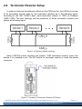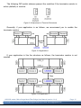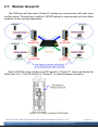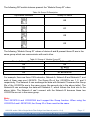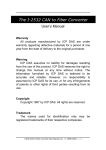
1
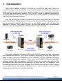
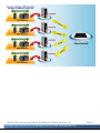
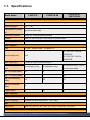
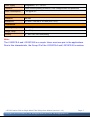
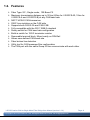
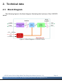
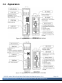
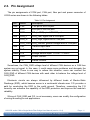
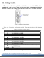
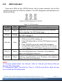
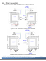
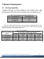
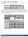
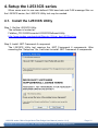
I-2533CS series
User Manual
Version 1.0.0, Sep. 2013
Service and usage information for
I‐2533CS / I‐2533CS‐60 / I‐2533CS‐A / I‐2533CS‐B
I-2533CS series CAN to Single Mode Fiber Bridge User Manual (version 1.0.0)
Copyright © 2013 ICP DAS Co., Ltd. All Rights Reserved. E-mail: [email protected]
Page: 1 Warranty
All products manufactured by ICP DAS are under warranty regarding defective
materials for a period of one year, beginning from the date of delivery to the
original purchaser.
Warning
ICP DAS assumes no liability for any damage resulting from the use of this
product.ICP DAS reserves the right to change this manual at any time without
notice. The information furnished by ICP DAS is believed to be accurate and
reliable. However, no responsibility is assumed by ICP DAS for its use, not for any
infringements of patents or other rights of third parties resulting from its use.
Copyright
Copyright @ 2013 by ICP DAS Co., Ltd. All rights are reserved.
Trademark
The names used for identification only may be registered trademarks of their
respective companies.
Contact us
If you have any problem, please feel free to contact us.
You can count on us for quick response.
Email: [email protected]
I-2533CS series CAN to Single Mode Fiber Bridge User Manual (version 1.0.0)
Copyright © 2013 ICP DAS Co., Ltd. All Rights Reserved. E-mail: [email protected]
Page: 2 Table of Contents 1. Introduction ..................................................................................................... 4
1.1. Specifications ............................................................................................ 6
1.2. Features ..................................................................................................... 8
2. Technical data.................................................................................................. 9
2.1. Block Diagram .......................................................................................... 9
2.2. Appearance ............................................................................................. 10
2.3. Pin Assignment ........................................................................................11
2.4. Rotary Switch ......................................................................................... 12
2.5. LED Indicator......................................................................................... 13
2.6. Terminator Resistor Setup..................................................................... 14
2.7. Module Group ID ................................................................................... 16
2.8. Wire Connection ..................................................................................... 18
3. Network Deployment ..................................................................................... 19
3.1. Driving Capability.................................................................................. 19
3.2. Fiber Selection & Fiber Length............................................................. 20
4. Setup the I-2533CS series ............................................................................. 21
4.1. Install the I-2533CS Utility .................................................................... 21
4.2. Setting up the I-2533CS series............................................................... 24
4.2.1. User-defined CAN Baud Rate Configuration ................................ 25
4.2.2. CAN Filter Configuration................................................................ 26
4.2.2.1. Configure a CAN Filter to the I-2533CS ................................... 27
4.2.2.2. Download Existent CAN Filter File to the I-2533CS................ 32
4.2.2.3. Read the I-2533CS CAN Filter Configuration.......................... 33
5. Firmware Upgrade ........................................................................................ 34
6. Dimension...................................................................................................... 37
I-2533CS series CAN to Single Mode Fiber Bridge User Manual (version 1.0.0)
Copyright © 2013 ICP DAS Co., Ltd. All Rights Reserved. E-mail: [email protected]
Page: 3 1. Introduction
The I-2533CS series (I-2533CS, I-2533CS-60, I-2533CS-A and I-2533CS-B) is a
local CAN bridge used to establish a connection between two CAN bus system via
single mode fiber optic transmission medium. In order to solve the problem between
CAN and fiber transmission medium, The I-2533CS series is specially designed for
converting the electrical CAN bus signal to fiber optic cables. Besides, I-2533CS series
has three more important features.
First, the transmission distance limitation of the CAN bus system will not affected
due to the different CAN baud rate. It means that the total CAN bus working distance
can be extended. Second, the bus error on one CAN network will not affect the
operation of another CAN network. Finally, the two CAN network can communication
with each other by using different CAN baud rate for highly flexibility.
The mainly difference between I-2533 and I-2533CS series are fiber connectors
and transmission distance. The I-2533CS series is designed for single mode fiber, and
allow to extern CAN bus to maximum 30 km. Besides, I-2533CS provides the group
function, which is the basic message router. Users can decide the CAN message flows
between several CAN bus systems. I-2533CS series also provides the utility tool for
user-defined baud rate and filter configuration. By using this tool, it is allowed to have
user-defined baud rate and CAN message filter. When users use the I-2533CS series
on two CAN network with different CAN baud rate, it may be useful to reduce the bus
loading of the network which has low baud rate. I-2533CS series CAN to Single Mode Fiber Bridge User Manual (version 1.0.0)
Copyright © 2013 ICP DAS Co., Ltd. All Rights Reserved. E-mail: [email protected]
Page: 4 I-2533CS series CAN to Single Mode Fiber Bridge User Manual (version 1.0.0)
Copyright © 2013 ICP DAS Co., Ltd. All Rights Reserved. E-mail: [email protected]
Page: 5 1.1. Specifications
Model Name
I-2533CS
I-2533CS-A /
I-2533CS-B
I-2533CS-60
CAN Interface
Connector
Screwed terminal block (CAN_GND, CAN_L, CAN_H)
Baud Rate (bps)
10 k ~ 1 M
Transmission Distance
Depend on baud rate
(m)
Terminator Resistor
Switch for 120Ω terminator resistor
Isolation
3000 VDC for DC-to-DC, 2500 Vrms for photo-couple
Specification
ISO 11898-2, CAN 2.0A and CAN 2.0B
Fiber Interface
Type
SC type ; Single mode ; 100 Base-FX
TX: 1310, RX: 1550 for
I-2533CS-A
TX: 1550, RX: 1310 for
I-2533CS-B
Wave Length (nm)
1310
Fiber Cable (μm)
8.3/125, 8.7/125, 9/125 or 10/125
Transmission Distance
30 (indicative only)
(km)
60 (indicative only)
15 (indicative only), (9/125
μm recommended)
Min. TX Output (dBm)
-15
-5
-8
Max. TX Output (dBm)
-8
0
-14
Max. RX Sensitivity
(dBm)
-34
-35
-31
Max. RX Overload
(dBm)
-5
Budget (dBm)
19
0
30
23
UART Interface
COM1
RS-232 (configuration only)
COM1 Connector
Screwed terminal block (RXD, TXD, GND)
LED
Round LED
PWR, FB_Ack, FB_Err, CAN_Err, CAN_Tx and CAN_Rx LEDs
Power
I-2533CS series CAN to Single Mode Fiber Bridge User Manual (version 1.0.0)
Copyright © 2013 ICP DAS Co., Ltd. All Rights Reserved. E-mail: [email protected]
Page: 6 Power supply
Unregulated +10 ~ +30 VDC
Protection
Power reverse polarity protection, Over-voltage brown-out protection
Power Consumption
0.125 @ 24VDC
Mechanism
Installation
DIN-Rail
Dimensions
33.0 mm x 126 mm x 101 mm (W x L x H)
Environment
Operating Temp.
-25 ~ 75 ℃
Storage Temp.
-30 ~ 80 ℃
Humidity
10 ~ 90% RH, non-condensing
Note:
The I-2533CS-A and I-2533CS-B is a couple. Users must use pair in the applications.
Due to this characteristic, the Group ID of the I-2533CS-A and I-2533CS-B is useless.
I-2533CS series CAN to Single Mode Fiber Bridge User Manual (version 1.0.0)
Copyright © 2013 ICP DAS Co., Ltd. All Rights Reserved. E-mail: [email protected]
Page: 7 1.2. Features
¾ Fiber Type: SC ; Single mode ; 100 Base-FX
¾ Maximum transmission distance up to 30 km (60km for I-2533CS-60, 15km for
I-2533CS-A and I-2533CS-B) at any CAN baud rate
¾ NXP TJA1042 CAN transceiver
¾ 2500 Vrms isolation on the CAN side
¾ Supports both CAN 2.0A and CAN 2.0B
¾ Fully compatible with the ISO 11898-2 standard
¾ Rotary switch for CAN baud rate configuration
¾ Build-in switch for 120 Ω terminator resistor
¾ Removable terminal block, Mount easily on DIN-Rail
¾ Allows user-defined CAN baud rate
¾ Fiber broken line detection
¾ Utility tool for CAN message filter configuration
¾ The CAN port with the same Group ID can communicate with each other
I-2533CS series CAN to Single Mode Fiber Bridge User Manual (version 1.0.0)
Copyright © 2013 ICP DAS Co., Ltd. All Rights Reserved. E-mail: [email protected]
Page: 8 2. Technical data
2.1. Block Diagram
The following figure is the block diagram illustrating the functions of the I-2533CS
series.
Figure 2-1 Block Diagram of I-2533CS series
I-2533CS series CAN to Single Mode Fiber Bridge User Manual (version 1.0.0)
Copyright © 2013 ICP DAS Co., Ltd. All Rights Reserved. E-mail: [email protected]
Page: 9 2.2. Appearance
Figure 2-2 Appearance of I-2533CS and I-2533CS-60
Figure 2-3 Appearance of I-2533CS-A and I-2533CS-B
I-2533CS series CAN to Single Mode Fiber Bridge User Manual (version 1.0.0)
Copyright © 2013 ICP DAS Co., Ltd. All Rights Reserved. E-mail: [email protected]
Page: 10 2.3. Pin Assignment
The pin assignments of COM port, CAN port, fiber port and power connector of
I-2533 series are shown in the following tables.
Table 2-1 Pin Assignment
Port
Name
Description
COM
TXD
TXD pin of RS-232 port.
RXD
RXD pin of RS-232 port.
GND
SG (or GND) pin of RS-232 port.
CAN_L
CAN_Low, signal line of CAN port.
CAN_H
CAN_High, signal line of CAN port.
CAN
CAN_GND CAN_Ground, ground voltage level of CAN port.
Fiber
TxD
Transmit optic data.
RxD
Receive optic data.
Power +VS
Voltage Source Input. +10VDC ~ +30VDC.
GND
Power Ground.
F.G.
Frame Ground.
Sometimes, the CAN_GND voltage level of different CAN devices on a CAN bus
system are not equal. In this case, it could cause some problems and derogate the
system stability. There is one way to relieve this situation; users can connect the
CAN_GND of different CAN devices with each other to balance the voltage level of
CAN_GND.
Electronic circuits are always influenced by different levels of Electro-Static
Discharge (ESD), which become worse in a continental climate area. F.G. provides a
path for conducting the ESD to the earth ground. Therefore, connecting the F.G
correctly can enhance the capability of the ESD protection and improve the module’s
reliability.
Wiring of CAN_GND and F.G. is not necessary; users can modify the configuration
of wiring according to real applications.
I-2533CS series CAN to Single Mode Fiber Bridge User Manual (version 1.0.0)
Copyright © 2013 ICP DAS Co., Ltd. All Rights Reserved. E-mail: [email protected]
Page: 11 2.4. Rotary Switch
When users would like to update the module’s firmware or set the CAN baud rate,
message filter of the I-2533CS series, use the rotary switch on the upper of the power
connector to achieve this purpose. Users can find it on the top of the power connector.
Figure 2-4 Location of Rotary Switch
There are 16 sections on the rotary switch. They are described on the following
table.
Table 2-2 Description of Rotary Switch
Switch Value
0
1
2
3
4
5
6
7
8
9
A
B~D
E
F
Description
Set baud rate to 10 kbps
Set baud rate to 20 kbps
Set baud rate to 50 kbps
Set baud rate to 80 kbps
Set baud rate to 100 kbps
Set baud rate to 125 kbps
Set baud rate to 250 kbps
Set baud rate to 500 kbps
Set baud rate to 800 kbps
Set baud rate to 1 Mbps
Set baud rate to user-defined baud rate which is configured
by I-2533CS utility.
N/A
Set I-2533CS into firmware update mode.
Set I-2533CS into configuration mode.
I-2533CS series CAN to Single Mode Fiber Bridge User Manual (version 1.0.0)
Copyright © 2013 ICP DAS Co., Ltd. All Rights Reserved. E-mail: [email protected]
Page: 12 2.5.
LED Indicator
There are 6 LEDs on the I-2533CS series. One for power indication, two for fiber
indication and three for CAN bus indication. The LED assignment and description are
shown as follows.
Figure 2-5 LED Assignment of I-2533CS
Table 2-3 LED Description
LED Name
PWR
Color
Red
FB_Ack
Green
FB_Err
Orange
CAN_Err
Red
CAN_Tx
Green
CAN_Rx
Green
Description
When power on the I-2533CS series, this LED is turned on.
When the I-2533CS series sends/receives one message
to/from the fiber, this LED flashes once.
If the I-2533CS series detects the RXD line of the fiber is off,
this LED is always on.
1. If the I-2533CS series detects the bus-off status on the
CAN bus, this LED is always on.
2. If the CAN data buffer is full, this LED flashes once per
second.
3. If the I-2533CS series can’t send CAN messages
successfully because the bus connector is off or some
errors happen, this LED flashes five times per second.
When the I-2533CS series sends one CAN message to CAN
bus, this LED flashes once. Therefore, if bus loading is
heavy, the LED will be always on.
When the I-2533CS series receives one CAN message from
CAN bus, this LED flashes once. Therefore, if bus loading is
heavy, the LED will be always on.
NOTE:
In “Firmware Update Mode”, the CAN_Err, CAN_Tx, CAN_Rx and FB_Err LEDs will
flash per 500 milliseconds.
In “Configuration Mode”, the CAN_Err, CAN_Tx, CAN_Rx and FB_Err LEDs will take
turns to flash per 500 milliseconds.
I-2533CS series CAN to Single Mode Fiber Bridge User Manual (version 1.0.0)
Copyright © 2013 ICP DAS Co., Ltd. All Rights Reserved. E-mail: [email protected]
Page: 13 2.6. Terminator Resistor Setup
In order to minimize the reflection effects on the CAN bus line, the CAN bus line has
to be terminated at both ends by two terminator resistors as in the following figure.
According to the ISO 11898-2 spec, each terminator resistor is 120Ω (or between
108Ω~132Ω). The bus topology and the positions of these terminator resistors are
shown as following figure.
Figure 2.6 CAN bus network topology
Each I-2533CS series includes one build-in 120Ω terminator resistor, users can
decide if it is enabled or not. The DIP switch for terminator resistor is under the power
connector.
Figure 2-7 Location of Terminator Resistor DIP Switch
I-2533CS series CAN to Single Mode Fiber Bridge User Manual (version 1.0.0)
Copyright © 2013 ICP DAS Co., Ltd. All Rights Reserved. E-mail: [email protected]
Page: 14 The following DIP switch statuses present the condition if the terminator resistor is
active (default) or inactive.
Figure 2-8 Adjustment of Terminal Resistance
Generally, if your application is as follows, we recommend you to enable the
terminator resistor.
Figure 2-9 Application 1
If your application is like the structure as follows, the terminator resistor is not
needed.
Figure 2-10 Application 1
I-2533CS series CAN to Single Mode Fiber Bridge User Manual (version 1.0.0)
Copyright © 2013 ICP DAS Co., Ltd. All Rights Reserved. E-mail: [email protected]
Page: 15 2.7. Module Group ID
The CAN port with the same “Group ID” setting can communicate with each other
via fiber optics. This setting is used for I-2533CS series to communicate with the others
modules on star topology application.
Each I-2533CS series includes one DIP switch for “Group ID”. Users can decide the
value from 0 to 3. The DIP switch for “Group ID” is under the power connector. Figure 2-11 Location of Group ID DIP Switch
I-2533CS series CAN to Single Mode Fiber Bridge User Manual (version 1.0.0)
Copyright © 2013 ICP DAS Co., Ltd. All Rights Reserved. E-mail: [email protected]
Page: 16 The following DIP switch statuses present the “Module Group ID” value.
Table 2-4 Group ID Description
Dip switch statuses
Group ID value
00
01
02
03
The following “Module Group ID” values of device A and B present these ID are in the
same group which can communicate with each other.
Table 2-5 Group of “Module Group ID”
Device A Group ID value
00
01
02
03
Device B Group ID value
00
01 or 03
02 or 03
01 or 02 or 03
For example, there are three CAN networks, Network A, Network B and Network C, and
each of them uses one I-2533CS. The Group IDs of the I-2533CSs are 1, 2, and 3
respectively. The Network A can exchange the data with Network C because the Group
IDs of the I-2533CSs are in the same group (the second rule in the above table). The
Network B can exchange the data with Network C, which follows the third rule in the
above table. The Network A can’t connect with the Network B because these two
I-2533CSs are not in the same group.
Note:
The I-2533CS-A and I-2533CS-B don’t support the Group function. When using the
I-2533CS-A and I-2533CS-B, the Group ID of them must be the same.
I-2533CS series CAN to Single Mode Fiber Bridge User Manual (version 1.0.0)
Copyright © 2013 ICP DAS Co., Ltd. All Rights Reserved. E-mail: [email protected]
Page: 17 2.8. Wire Connection
The wire connection of the I-2533CS series is displayed below.
Figure 2-12 Wire Connection for I-2533CS and I-2533CS-60
Figure 2-13 Wire Connection for I-2533CS-A and I-2533CS-B
I-2533CS series CAN to Single Mode Fiber Bridge User Manual (version 1.0.0)
Copyright © 2013 ICP DAS Co., Ltd. All Rights Reserved. E-mail: [email protected]
Page: 18 3. Network Deployment
3.1. Driving Capability
Before introducing the driving capability of the I-2533CS series, some
characteristics of copper cable must be assumed. The AC parameters are 120Ω
impedance and 5ms/, line delay, and the DC parameter follows the table show below.
Table 3-1 Recommended DC parameter for CAN Bus Line
Wire Cross-Section [mm2]
~0.25 (AWG23)
~0.5 (AWG20)
~0.8 (AWG18)
~1.3 (AWG16)
Resistance [Ω/km]
< 90
< 50
< 33
< 20
Under the condition described above, users can refer to the following table to know
the maximum node number in each segment following ISO 11898-2 and the maximum
segment length when using different type of wire.
Table 3-2 Driving Capability
Wire Cross-Section
[mm2]
~0.25 (AWG23)
~0.5 (AWG20)
~0.8 (AWG18)
~1.3 (AWG16)
The maximum segment length [m] under the case of
specific node number in this segment
16 Nodes
32 Nodes
64 Nodes
100 Nodes
< 220
< 200
< 170
< 150
< 390
< 360
< 310
< 270
< 590
< 550
< 470
< 410
< 980
< 900
< 780
< 670
I-2533CS series CAN to Single Mode Fiber Bridge User Manual (version 1.0.0)
Copyright © 2013 ICP DAS Co., Ltd. All Rights Reserved. E-mail: [email protected]
Page: 19 3.2. Fiber Selection & Fiber Length
The specification of fiber cable used to connect the I-2533CS series is shown as
following table.
Table 3-3 Specification of Fiber
Type
Diameter [μm]
(Core/Cladding)
Operating
Wavelength [nm]
Single mode
8.3/125, 8.7/125,
9/125 or 10/125
1310
The I-2533CS series allows maximum 30km fiber length for each kind of CAN baud.
Although the maximum fiber length has no relationship with the CAN baud rate, but
some fiber attributions, such as attenuation, still influence it. Higher attenuation of fiber
will reduce the transmission distance. User can use following table to know the
relationship between those two.
Table 3-4 The relationship between CAN baud rate and indicative Fiber length
Module Name
I-2533CS
I-2533CS-60
I-2533CS-A /
I-2533CS-B
CAN Baud
Rate [bit/sec]
1 M ~ 10 k
Allowed Fiber length [km]
30
60
15
Table 3-5 Attenuation & Fiber Length
Module Name
I-2533CS
I-2533CS-60
I-2533CS-A /
I-2533CS-B
Attenuation
[dB/km]
0.4
> 0.4
0.4
> 0.4
0.4
> 0.4
Allowed Fiber length [km]
30
< 30
60
< 60
15
< 15
I-2533CS series CAN to Single Mode Fiber Bridge User Manual (version 1.0.0)
Copyright © 2013 ICP DAS Co., Ltd. All Rights Reserved. E-mail: [email protected]
Page: 20 4. Setup the I-2533CS series
When users want to use user-defined CAN baud rate and CAN message filter on
the I-2533CS series, the I-2533CS Utility tool may be needed.
4.1. Install the I-2533CS Utility
Step 1: Get the I-2533CS Utility
The software is located at:
Fieldbus_CD:\CAN\Converter\I-2533CS\Software\Utility
http://www.icpdas.com/products/Remote_IO/can_bus/i-2533cs.htm
Step 2: Install .NET Framework 4 component
The I-2533CS Utility tool requires the .NET Framework 4 components. After
executing the “Setup.exe” file, it will start to install .NET Framework 4 components.
I-2533CS series CAN to Single Mode Fiber Bridge User Manual (version 1.0.0)
Copyright © 2013 ICP DAS Co., Ltd. All Rights Reserved. E-mail: [email protected]
Page: 21 Step 3: Install Utility tool
After installing the .Net Framework components, the software will continue to install
the Utility tool.
1. Click the “Next” button to continue.
2. Select the installation path of the I-2533CS Utility and click the “Next” button.
I-2533CS series CAN to Single Mode Fiber Bridge User Manual (version 1.0.0)
Copyright © 2013 ICP DAS Co., Ltd. All Rights Reserved. E-mail: [email protected]
Page: 22 3. Confirm the installation. Click the “Next” button to start the installation
4. Installation complete. Click the “Close” button to exit
I-2533CS series CAN to Single Mode Fiber Bridge User Manual (version 1.0.0)
Copyright © 2013 ICP DAS Co., Ltd. All Rights Reserved. E-mail: [email protected]
Page: 23 4.2. Setting up the I-2533CS series
After installing the utility tool, please follow the following steps to set up the
communication between the Utility and the I-2533CS series. Here is the example for the
I-2533CS configuration.
Step 1: Power off the I-2533CS.
Step 2: Set the rotary switch to ‘F’ and connect the PC available COM port with the
COM port of the I-2533CS. Users can find the communication cable (CA-0910)
in the product box. When connecting to the COM port of I-2533CS, the TXD pin
of the cable is connected to the TXD pin of the I-2533CS COM port, RXD pin of
the cable is connected to the RXD pin of the I-2533CS COM port, and GND pin
of the cable is connected to the GND pin of the I-2533CS COM port.
Figure 4-1 Wire connection of the RS-232
Step 3: Power on the I-2533CS. Then, the CAN_Err, CAN_Tx, CAN_Rx, FB_Err LEDs
will take turns to flash per 500 milliseconds.
Step 4: Execute the I-2533CS Utility tool.
I-2533CS series CAN to Single Mode Fiber Bridge User Manual (version 1.0.0)
Copyright © 2013 ICP DAS Co., Ltd. All Rights Reserved. E-mail: [email protected]
Page: 24 4.2.1.
User-defined CAN Baud Rate Configuration
The I-2533CS series allows users to set the special CAN baud rate by using the
“User-defined CAN Baud Rate” field of the Utility.
Figure 4-2 Set and read the CAN filter configuration
The CAN bus baud rate is calculated by the parameter BRP (Baud Rate Prescaler),
TSEG1 (The delay from the nominal Sync point to the sample point minus one) and
TSEG2 (The delay from the sample point to the next nominal sync point minus one).
Please refer to the following formula to calculate the BRP, TSEG1 and TSEG2
parameters of your expected CAN baud rate and click the “Save” button to download
this parameter into module.
Expected CAN baud rate = 48000 / ((BRP +1) * (TSEG1 + TESG2 + 3))
Note:
BRP:
TSEG1:
TSEG2:
(Kbps)
Baud Rate Prescaler.
Range: 0x000 ~ 0x3FF
The delay from the nominal Sync point to the sample point minus one.
Range: 0x0 ~ 0xF
The delay from the sample point to the next nominal sync point minus one.
Range: 0x0 ~ 0x7
Example:
Expected CAN baud rate = 1000 Kbps
BRP: 0x003
TSEG1: 0x9
TSEG2: 0x0
1000 (Kbps) = 48000 / ((3 +1) * (9 + 0 + 3))
I-2533CS series CAN to Single Mode Fiber Bridge User Manual (version 1.0.0)
Copyright © 2013 ICP DAS Co., Ltd. All Rights Reserved. E-mail: [email protected]
Page: 25 4.2.2.
CAN Filter Configuration
There are two parts of CAN filter configuration. One is “Download CAN Filter” which
functions as setting the CAN filter and downloading the configuration to the I-2533CS.
Another is “Read CAN Filter” which provides read back the CAN filter configuration form
the I-2533CS series.
Figure 4-3
Set and read the CAN filter configuration
Figure 4-4
CAN filter configuration dialog
I-2533CS series CAN to Single Mode Fiber Bridge User Manual (version 1.0.0)
Copyright © 2013 ICP DAS Co., Ltd. All Rights Reserved. E-mail: [email protected]
Page: 26 4.2.2.1. Configure a CAN Filter to the I-2533CS
When users set the CAN filter first time, they need use “Download CAN Filter” field.
Step 1: Click the “Create CAN Filter File” button to start setting CAN filter.
Figure 4-5 Create CAN filter file
Then users would see the following window pop-up.
Figure 4-6 CAN filter configuration dialog
I-2533CS series CAN to Single Mode Fiber Bridge User Manual (version 1.0.0)
Copyright © 2013 ICP DAS Co., Ltd. All Rights Reserved. E-mail: [email protected]
Page: 27 Step 2: Add the CAN filter with single CAN ID or group of CAN ID. The CAN message
with the ID in the list will be received, otherwise it will be dropped.
Figure 4-7 Add single or group of CAN filter
For example, if users want to pass the CAN ID 0x07F in the CAN 2.0B specification.
Firstly, select “29-bit ID” item in the “CAN Single CAN ID” field. Secondly, fill the value
“7F” in the edit box. Finally, click “Add” button in the “CAN x Single CAN ID” field.
Moreover, if users want to pass the CAN 2.0A messages with CAN ID 0x04 ~ 0x15
while these messages are received by the CAN port 1 Firstly, select “11-bit ID” item in
the “CAN x Group CAN ID” field. Secondly, fill the value “4” in the “Start” field and the
value “15” in the “End” field. Finally, click “Add” button in the “CAN x Group CAN ID”
field.
I-2533CS series CAN to Single Mode Fiber Bridge User Manual (version 1.0.0)
Copyright © 2013 ICP DAS Co., Ltd. All Rights Reserved. E-mail: [email protected]
Page: 28 After completing those two examples, users could see the follow picture.
Figure 4-8 Two CAN filter data
The “No.” field shows the sequential number for each record of the CAN filter
configuration.
The “CAN Port” field indicates the record is belong to which CAN port.
The “Accepted IDs” field displays that which CAN ID would be received.
An icon in the head of the line may represent the following information.
: This record is the CAN filter of 11-bit and single CAN ID.
: This record is the CAN filter of 11-bit and group CAN ID.
: This record is the CAN filter of 29-bit and single CAN ID.
: This record is the CAN filter of 29-bit and group CAN ID.
I-2533CS series CAN to Single Mode Fiber Bridge User Manual (version 1.0.0)
Copyright © 2013 ICP DAS Co., Ltd. All Rights Reserved. E-mail: [email protected]
Page: 29 Step 3: When completing the CAN filter configuration, click the “Save to File” button to
save it by using a record file with “*.FLT” extension file name.
Figure 4-9 Five buttons in CAN filter configuration dialog
There are more five buttons to help users configuring the CAN filter.
1. “Clear Table” button would delete all CAN filter records in the list.
2. “Delete Select” button would delete the selected CAN filter record.
3. “Load from File” button allows users to load the configuration from the existent CAN
filter file (*.FLT).
4. “Save to File” button provides the function to save the current CAN filter configuration
into a file (*.FLT).
5. “OK” button would exit the configuration dialog.
I-2533CS series CAN to Single Mode Fiber Bridge User Manual (version 1.0.0)
Copyright © 2013 ICP DAS Co., Ltd. All Rights Reserved. E-mail: [email protected]
Page: 30 Step 4: Check the “Enable CAN Filter” item to make the CAN filter enable.
Figure 4-10 CAN filter status
Step 5: Click “Download CAN Filter File” to download the selected CAN filter file into the
I-2533CS series.
Figure 4-11 Download CAN filter data
After finishing all the steps above, users need to reset the module to enable the
configuration by turning it off and then turning it on. If users want to review the
configuration, click “Read From Module” button to read back the information.
I-2533CS series CAN to Single Mode Fiber Bridge User Manual (version 1.0.0)
Copyright © 2013 ICP DAS Co., Ltd. All Rights Reserved. E-mail: [email protected]
Page: 31 4.2.2.2. Download Existent CAN Filter File to the I-2533CS
The steps are the same as step 4 and 5 of the section 4.2.2.1. Step 1: Check the “Enable CAN Filter” item to make the CAN filter enable.
Figure 4-12 CAN filter status
Step 2: Click “Download CAN Filter File” to download the selected CAN filter file into the
I-2533CS series.
Figure 4-13 Download CAN filter data
After finishing all the steps above, users need to reset the module to enable the
configuration by turning it off and then turning it on. If users want to review the
configuration, click “Read From Module” button to read back the information. I-2533CS series CAN to Single Mode Fiber Bridge User Manual (version 1.0.0)
Copyright © 2013 ICP DAS Co., Ltd. All Rights Reserved. E-mail: [email protected]
Page: 32 4.2.2.3. Read the I-2533CS CAN Filter Configuration
Click the “Read from Module” to read the CAN filter setting from the I-2533CS
series.
Figure 4-14 Read CAN filter form the I-2533CS
If reading the CAN filter data successfully, users would see the configuration dialog
such as “Create CAN Filter File”. Users can modify the CAN filter setting if necessary, or
save it into a file.
Figure 4-15 CAN filter id setting
I-2533CS series CAN to Single Mode Fiber Bridge User Manual (version 1.0.0)
Copyright © 2013 ICP DAS Co., Ltd. All Rights Reserved. E-mail: [email protected]
Page: 33 5. Firmware Upgrade
Please refer to the following steps to upgrade the firmware of module. Here uses
the I-2533CS for example.
Step 1: Power off the I-2533CS.
Step 2: Set the rotary switch to ‘E’ and connect the PC available COM port with the
COM port of the I-2533CS. Users can find the communication cable (CA-0910)
in the product box. When connecting to the COM port of I-2533CS, the TXD pin
of the cable is connected to the TXD pin of the I-2533CS COM port, RXD pin of
the cable is connected to the RXD pin of the I-2533CS COM port, and GND pin
of the cable is connected to the GND pin of the I-2533CS COM port.
Figure 5-1 Wire connection of the RS-232
Step 3: Power on the I-2533CS. Then, the CAN_Err, CAN_Tx, CAN_Rx, FB_Err LEDs
will flash per 500 milliseconds.
Step 4: Get the “Firmware Update Tool” and firmware fire.
The software is located at:
Fieldbus_CD:\CAN\Converter\I-2533CS\Software\Tool
The firmware is located at:
Fieldbus_CD:\CAN\Converter\I-2533CS\Firmware\
http://www.icpdas.com/products/Remote_IO/can_bus/i-2533cs.htm
I-2533CS series CAN to Single Mode Fiber Bridge User Manual (version 1.0.0)
Copyright © 2013 ICP DAS Co., Ltd. All Rights Reserved. E-mail: [email protected]
Page: 34 Step 5: Execute the “Firmware Update Tool”.
Step 6: Select the necessary COM port of PC.
I-2533CS series CAN to Single Mode Fiber Bridge User Manual (version 1.0.0)
Copyright © 2013 ICP DAS Co., Ltd. All Rights Reserved. E-mail: [email protected]
Page: 35 Step 7: Press the the “Browser…” button and select the firmware file (*.fw).
Step 8: Press the “Firmware Update” button to update the firmware. After successfully to
update the firmware, the “Firmware Update Success! Please Reboot Module!”
information will be display on the “3. Firmware Update” frame.
Step 9: Reboot the module and press the “Exit” button to exit.
I-2533CS series CAN to Single Mode Fiber Bridge User Manual (version 1.0.0)
Copyright © 2013 ICP DAS Co., Ltd. All Rights Reserved. E-mail: [email protected]
Page: 36 6. Dimension
I-2533CS series CAN to Single Mode Fiber Bridge User Manual (version 1.0.0)
Copyright © 2013 ICP DAS Co., Ltd. All Rights Reserved. E-mail: [email protected]
Page: 37