1
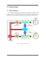
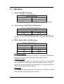
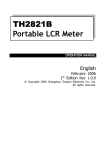
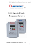
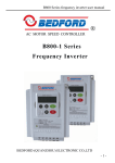
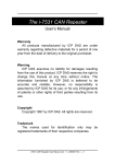
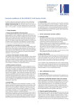
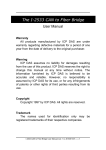
The I-7532 CAN Bridge
User’s Manual
Warranty
All products manufactured by ICP DAS are under
warranty regarding defective materials for a period of one
year from the date of delivery to the original purchaser.
Warning
ICP DAS assumes no liability for damages resulting
from the use of this product. ICP DAS reserves the right to
change this manual at any time without notice. The
information furnished by ICP DAS is believed to be
accurate and reliable. However, no responsibility is
assumed by ICP DAS for its use, or for any infringements
of patents or other rights of third parties resulting from its
use.
Copyright
Copyright 1997 by ICP DAS. All rights are reserved.
Trademark
The names used for identification only may be
registered trademarks of their respective companies.
I-7532 CAN Bridge User Manual (ver. 1.0, 2008/08/25) ------1
Tables of Content
Tables of Content...........................................................................................2
1 Introduction.............................................................................................3
1.1 Features..........................................................................................5
1.2 Specifications.................................................................................6
2
3
1.3 Application .....................................................................................6
1.4 Information .....................................................................................6
Technical data .........................................................................................7
2.1 Block Diagram................................................................................7
2.2
2.3
2.4
Appearance ....................................................................................8
LED Status......................................................................................9
Reset & Error Clear Button .........................................................10
2.5
2.6
2.7
2.8
Baudrate Selection Switch..........................................................10
Pin Assignment............................................................................ 11
Wire Connection ..........................................................................13
Terminator Resistor Setting........................................................14
Network deployment ............................................................................15
3.1 Definition ......................................................................................15
3.2 Cable Selection ............................................................................15
3.3 Driving Capability ........................................................................16
3.4
3.5
Baud and Bus Length..................................................................16
Terminator Resistor .....................................................................17
I-7532 CAN Bridge User Manual (ver. 1.0, 2008/08/25) ------2
1 Introduction
I-7532 is a local CAN bridge used to establish a connection between two
CAN bus system in a CAN network. I-7532 stands by itself connecting adjacent
wiring segments together as in the case of a CAN repeater (I-7531). Not just
like a CAN repeater, I-7532 has two more powerful features (Extend Network
Distance and Connect two networks with different baud rate).
Figure 1-1
I-7532
The I-7532 is an optically isolated CAN bridge which provides 2500VRMS
optical isolation allowing users to separate and protect critical segments of the
CAN network. And it is 3000VDC galvanic isolation isolates both CAN channels
from each other as well as from the power supply. The CAN connection of
I-7532 is by terminal blocks. A power supply of 10 ~ 30VDC is required. I-7532
is housed in a rugged DIN-Rail mountable box, making it easy to install in an
industrial cabinet.
I-7532 CAN Bridge User Manual (ver. 1.0, 2008/08/25) ------3
Figure 1-2
Application of I-7532 Extend Distance.
The transmission distance limitation of the CAN bus system on each side
of I-7532 are independent, which means the total network distance can be
extended
Figure 1-3
Application of I-7532 Different Baud Connected.
The baud rate of two channels on I-7532 can be different for highly
flexibility. On the other hand, when the CAN bus system on one side of I-7532
happens some error (e.g. bit error), the system on other side can still work on
correctly
I-7532 CAN Bridge User Manual (ver. 1.0, 2008/08/25) ------4
Figure 1-4
Application of I-7532 Raise node.
I-7532 can enhance the bus load capacity, and users can know how to
increase driving capability by table 3-2.
1.1 Features
Microprocessor inside with 72MHz.
82C250 CAN transceiver.
2500VRMS photo couple isolation on the CAN side.
3000VDC galvanic isolation among the power supply and 2 CAN
channel.
120Ω CAN terminal resistors are integrated (can be disabled by
jumper).
Watchdog inside.
Driving capability: Up to 100 nodes on each CAN channel.
Transmission distance up to 1km on each CAN channel.
Removable terminal block.
Mountable on DIN Rail.
768 frames buffer for each CAN channel.
The baud of each channel can be different for highly flexibility.
I-7532 CAN Bridge User Manual (ver. 1.0, 2008/08/25) ------5
1.2 Specifications
Support CAN 2.0A / CAN 2.0B.
Fully compatible with ISO 11898-2.
Communication baud : 5K, 10K, 20K, 50K, 80K, 100K, 125K, 200K,
250K, 400K, 500K, 600K, 800K and 1Mbps.
Power consumption: 2W max.
Power Supply: +10VDC ~ +30VDC.
Operating temperature: -25°C ~ +75°C.
Humidity: 5% ~ 95%.
Dimensions: 122 mm x 72 mm x 35 mm.
1.3 Application
Factory Automation.
Building Automation.
Home Automation.
Vehicle Automation.
Control system.
Monitor system.
1.4 Information
For more information about the I-7532, please visit our website:
http://www.icpdas.com/products/Remote_IO/can_bus/i-7532.htm
I-7532 CAN Bridge User Manual (ver. 1.0, 2008/08/25) ------6
2 Technical data
2.1 Block Diagram
The following block diagram illustrates the functions of I-7532 module.
Power supply is with 3000VDC galvanic isolated between each CAN port.
Furthermore, there is photo-isolation 2500VRMS between two CAN channels.
CAN
Channel 1
CAN_H
DC
DC
Physical CAN layer
3000VDC
Galvanic Isolation
120Ω
CAN_L
2500VRMS
Photo Isolation
CAN Bridge
3000VDC
Galvanic isolation
2500VRMS
Photo Isolation
CAN
Channel 2
CAN_H
Power
Regulator
DC
DC
Physical CAN layer
120Ω
Block Diagram of I-7532
+10VDC ~ +30VDC
Figure 2-1
Block Diagram of I-7532
I-7532 CAN Bridge User Manual (ver. 1.0, 2008/08/25) ------7
CAN_L
2.2 Appearance
CAN Channel 2
CAN_L
FG2
CAN_H
CAN_GND
CAN_L
FG1
CAN CH 1
11 CAN_GND
20
CAN_H
CAN Channel 1
CAN CH 2
Power &
Communication
Error LED
PWR
LED
CH1 ERR
i-7532
CH1 Rx
CH2 ERR
CH2 Rx
CAN Bus Bridge
‧Support CAN 2.0A/2.0B
‧Selectable 120O terminal resistor
‧Rotary switch value & Baud :
RSW
1
2
Baud
5K
10K
20K
9
A
B
RSW
Baud
3
4
5
6
7
8
40K
50K
80K
100K 125K
C
D
E
F
200K 250K 400K 500K 600K 800K
1M
(B)GND
(R)VS+
FG3
RST &
Err Clear
CH2 Baud
CH1 Baud
1
10
3KV VDC Isolation on each CAN side
Power Input
Baud Switch
Reset & Error
Clear Button
Figure 2-2
Appearance of I-7532
I-7532 CAN Bridge User Manual (ver. 1.0, 2008/08/25) ------8
2.3 LED Status
Power LED(PWR LED) Status
Table 2-1
Power LED Status
PWR LED(Red Light)
ON
Power On
OFF
Power off
When I-7532 is active, the PWR LED will turn on with red light.
Communication LED(CH1RX,CH2RX) Status
Table 2-2
Communication LED Status
Rx LED(Green Light)
Flashing
Transmission
OFF
Bus Idle
If there is a message passing through I-7532 from channel 1 to
channel 2, the CH1 Rx LED will flash once with green light, and vice
versa.
Error LED(CH1 ERR, CH2 ERR) Status
Table 2-3
Error LED Status
ERR LED(Red Light)
Flashing (100ms)
Transmission Fail
Flashing (1sec)
Buffer overflow
ON
Bus Off
OFF
No Error
(1).Transmission Fail:
If CAN transmission fails on channel (X), the CH(X) ERR LED will
flash continuously and the flashing interval is about 100 ms.
(2).Buffer overflow:
If Tx buffer on channel (X) has been overflow, the CH(X) ERR
LED would flash continuously and the flashing interval is about 1
second. No matter the status is already fixed or not, after user click the
“RST” button, the Error LED will be off.
(3).Bus Off:
If Bus-Off condition happened on channel (X) of I-7532, the CH(X)
ERR LED will be always ON until corrected.
I-7532 CAN Bridge User Manual (ver. 1.0, 2008/08/25) ------9
2.4 Reset & Error Clear Button
Table 2-4
Reset &Error Clear Button
Reset & Error Clear Button
Click once
Clear Error LED
Press 3 sec
Module Reset
(1).Error Clear:
Users can click this button to clear the ERR LED status.
(2).Module Reset:
If users want to reset I-7532, just press “RST & Error Clean”
button until 3 sec, then all LEDs on I-7532 will flash once about 0.8
sec. After reset is finished, the PWR Led will be on and other LEDs
will be off.
2.5 Baud Selection Switch
Users can use the “Baud Rotary Switch” to change the CAN1 and CAN2
baud of I-7532 and it supports 15 kinds of baud on below table. After
changing the rotary switch value, users need to reset I-7532 to take the
setting effect ( by pressing RST button until 3 sec).
Table 2-5 Rotary Switch Value & Baud
Switch Value
0
1
2
3
4
5
6
7
Baud [bps]
NA.
5k
10k
20k
40k
50k
80k
100k
Switch Value
8
9
A
B
C
D
E
F
Baud [bps]
125k
200k
250k
400k
500k
600k
800k
1M
I-7532 CAN Bridge User Manual (ver. 1.0, 2008/08/25) ------10
2.6 Pin Assignment
1
20
CAN CH 1
CAN_H
FG1
CAN_L
CAN_GND
CAN CH 2
FG3
(R)VS+
CAN_H
FG2
CAN_L
(B)GND
10
11 CAN_GND
Figure 2-3 CAN & Power Connector of I-7532
Table 2-6 Pin Description of CAN Connector
Part
CAN
CH 1
CAN
CH 2
Name
Description
CAN_GND
CAN_Ground, ground voltage level of CAN channel 1.
CAN_L
CAN_Low, signal line of CAN channel 1.
FG1
Frame Ground of CAN channel 1.
CAN_H
CAN_High, signal line of CAN channel 1.
CAN_GND
CAN_Ground, ground voltage level of CAN channel 2.
CAN_L
CAN_Low, signal line of CAN channel 2.
FG2
Frame Ground of CAN channel 2.
CAN_H
CAN_High, signal line of CAN channel 2.
Table 2-7 Pin Description of Power Connector
Part
Power
Name
Description
(R)VS+
Voltage Source. It could be +10VDC ~ +30VDC.
(B)GND
Power Ground.
FG3
Frame Ground of Power.
I-7532 CAN Bridge User Manual (ver. 1.0, 2008/08/25) ------11
Note 1:
In some cases, the voltage level of CAN_GND of different CAN
device in the same CAN bus system are not equal. At this time, it
could cause some problems to derogate system stability of this
CAN bus system.
There is one way to relieve this situation; user can connect the
CAN_GND between those CAN devices to achieve equal
voltage level of CAN_GND.
Wiring of CAN_GND is not necessary; user can modify the
configuration of wiring according to actual applications.
Note 2:
Electronic circuits are constantly vulnerable to Electro-Static
Discharge (ESD), which become worse in a continental climate
area. FG(Frame Ground) provides a path for bypassing ESD to
earth ground, allowing enhanced static protection (ESD)
capability and ensures that the module is more reliable.
If user wants to use FG, the FG1 and FG2 and FG3 should be
connecting to earth ground. Within the I-7532, FG1 and FG2
and FG3 are not interconnected.
I-7532 CAN Bridge User Manual (ver. 1.0, 2008/08/25) ------12
2.7 Wire Connection
CAN_GND
CAN_L
Earth Ground
CAN_H
CAN CH 1
CAN_H
Earth Ground
CAN_L
CAN_GND
CAN CH 2
Power Ground
+10VDC ~ +30VDC
Earth Ground
Figure 2-4 Wire Connection of I-7532
I-7532 CAN Bridge User Manual (ver. 1.0, 2008/08/25) ------13
2.8 Terminator Resistor Setting
I-7532 includes two build-in 120Ω terminal resistors, users can decide to
enable these two terminal resistors or not.
The JP4 of I-7532 is used to adjust terminal resistor on CAN Channel 1,
and the JP3 of I-7532 is used to adjust terminal resistor on CAN Channel 2.
Before adjusting JP3 or JP4 of I-7532, users need to open the cover of
I-7532 first. The location of JP3 and JP4 is shown as follows:
JP4
JP3
Figure 2-5 JP3 and JP4 positions
The following connection statuses present the condition if the terminal
resistor is enabled (default) or disabled.
Disable
(Deactivate)
Enable
(Activate)
Figure 2-6 Adjustment of Terminator Resistor
I-7532 CAN Bridge User Manual (ver. 1.0, 2008/08/25) ------14
3 Network deployment
3.1 Definition
Following figure is the relation among segments in CAN bus and CAN
network.
Figure 3-1 Segment, CAN Bus and CAN network
3.2 Cable Selection
The CAN bus following ISO 11898-2 is a balanced (differential) 2-wire
interface running over either a Shielded Twisted Pair (STP), Un-shielded
Twisted Pair (UTP), or Ribbon cable.
The table below shows the recommended DC parameters of CAN bus
line.
Table 3-1 Recommended DC parameters for CAN Bus Line
Wire Cross-Section [mm2]
Resistance [Ω/km]
~0.25 (AWG23)
< 90
~0.5 (AWG20)
< 50
~0.8 (AWG18)
< 33
~1.3 (AWG16)
< 20
The recommended AC parameters of CAN bus line are 120Ω impedance
and 5 ns/m specific line delay.
I-7532 CAN Bridge User Manual (ver. 1.0, 2008/08/25) ------15
3.3 Driving Capability
Users can use the following table to know the maximum node number in
each segment and the maximum segment length when using different type of
wire in the CAN network
Table 3-2 Driving Capability
The maximum segment length [m] under the
case of specific node number in this segment
Wire CrossSection [mm2]
16 Nodes
32 Nodes
64 Nodes
100 Nodes
~0.25 (AWG23)
<220 m
<200 m
<170 m
<150 m
~0.5 (AWG20)
<390 m
<360 m
<310 m
<270 m
~0.8 (AWG18)
<590 m
<550 m
<470 m
<410 m
~1.3 (AWG16)
<980 m
<900 m
<780 m
<670 m
3.4 Baud and Bus Length
The relationship between ideal bus length and baud in the CAN bus
system is displayed below.
Table 3-3 Baud, Bus Length
Baud [bit/sec]
Ideal Bus Length[m]
1M
< 40
800K
< 50
500K
< 100
250K
< 250
125K
< 500
50K
< 1000
20K
< 2500
10K
< 5000
When users want to calculate the bus length, the device used to connect
CAN segment must be considered too. User can check the specification of the
device and find the equivalent bus length of the device. For example, the
equivalent bus length of CAN repeater (I-7531) is 40m.
I-7532 CAN Bridge User Manual (ver. 1.0, 2008/08/25) ------16
3.5 Terminator Resistor
According to the ISO 11898-2 specifications, the bus line of CAN_H and
CAN_L must be terminated by a terminal resistor for proper operation. The
equivalent resistance between CAN_H and CAN_L should be 60Ω. There are
some examples below.
Case1: RT = 120Ω
Case2: RT = 180Ω
CAN_H
CAN_H
RT
RT RT
RT
CAN_L
CAN_L
RT
Case3: RT1 = 180Ω, RT2 = 120Ω
CAN_H
RT1
RT1
RT2
CAN_L
CAN Repeater
or CAN Bridge
RT1
Figure 3-2 Terminator Resistor
I-7532 CAN Bridge User Manual (ver. 1.0, 2008/08/25) ------17
RT2