1
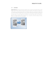
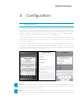
Videophone for iOS user manual . 1
DIVUS
VIDEOPHONE
Videophone for iOS user manual
Version 1.0
REV02-20150717
Videophone for iOS user manual . 2
GENERAL INFORMATION
DIVUS GmbH
Pillhof 51
I-39057 Eppan (BZ)
Operating instructions, manuals and software are protected by copyright. All rights are reserved. Copying, multiplication, translation and conversion, either partially or as a whole, is not permitted. You are allowed to make a
single copy for backup purposes.
We reserve the right to make changes to the manual without prior notification.
We assume no responsibility for any errors or omissions that may appear in this document.
We do not assume liability for the flawlessness and correctness of the programs and data contained on the
delivered discs.
You are always welcome to inform us of errors or make suggestions for improving the program.
The present agreement also applies to special appendices to the manual.
This manual can contain terms and descriptions, which inproper use by third can harm the copyrights of the
author.
Please read the manual before beginning and keep the manual for later use.
The manual has been conceived and written for users who are experienced in the use of PCs and automation
technology.
CONVENTIONS
[KEYS]
Keys that are to be pressed by the user are given in square brackets, e.g. [CTRL] or [DEL]
COURIER
On-screen messages are given in the Courier font, e.g. C:\>
COURIER BOLD
Keyboard input to be made by the user are given in Courier bold, e.g. C:\>DIR).
„…“
PICTOGRAMS
Names of buttons to be pressed, menus or other onscreen elements and product names are
given within double quotes. (e.g. “Configuration”).
In this manual the following symbolic are used to indicate particular text blocs.
Caution!
A dangerous situation may arise that may cause damage to material.
Hint
Hints and additional notes
New
New features
Videophone for iOS user manual . 3
INDEX:
1
2
3
GENERIC INFORMATION ___________________________________________________________________________ 4
1.1
INTRODUCTION ______________________________________________________________________________ 4
1.2
MINIMUM REQUIREMENTS ____________________________________________________________________ 4
1.3
LIMITATION _________________________________________________________________________________ 4
1.4
INSTALLATION _______________________________________________________________________________ 5
FUNCTIONALITY __________________________________________________________________________________ 6
2.1
USER INTERFACE ____________________________________________________________________________ 6
2.3
FUNCTIONALITY _____________________________________________________________________________ 8
2.3.1
VIDEO DOOR COMMUNICATION __________________________________________________________ 8
2.3.2
SPY-FUNCTION__________________________________________________________________________ 8
2.3.3
INTERPHONE ____________________________________________________________________________ 9
CONFIGURATION ________________________________________________________________________________ 10
3.1
CONFIGURATION MENU _____________________________________________________________________ 10
3.1.1
VOIP SETTINGS _________________________________________________________________________ 11
3.1.2
EXTERNAL/INTERNAL UNITS _____________________________________________________________ 11
3.1.2.1
PHONEBOOK ______________________________________________________________________ 11
3.1.2.2
SELECT SPY CAMERA ______________________________________________________________ 14
3.1.2.3
DOOR OPENER SETTINGS ___________________________________________________________ 14
3.1.3
GENERAL SETTINGS ____________________________________________________________________ 14
3.1.4
ABOUT ________________________________________________________________________________ 15
3.2
REMOTE FUNCTIONALITY ____________________________________________________________________ 16
4.1
IMPORTANT TERMSE ________________________________________________________________________ 17
4.3
NOTES _____________________________________________________________________________________ 19
Videophone for iOS user manual . 4
1
Generic information
1.1
INTRODUCTION
The app DIVUS VIDEOPHONE completes the DIVUS intercom portfolio and makes video communication possible
also on iOS devices. The app follows the Windows version of the Videophone-Software (now available in version
3.0) as well in functional as in design terms.
When starting the app for the first time, it will show a welcome message with some useful information. Before
being able to use the app, it namely has to be configured and integrated as VoIP member into the existing
system.
Note: This manual exclusively shows the configuration of the DIVUS VIDEOPHONE app and does not go deeper
into the intercom topic. Depending on the system in use, you can find more details regarding the whole setup
either in the manual of DIVUS VIDEOPHONE or in the ones of KNXCONTROL. In order to use the app it is
required that a configured and working VoIP server is present in the system and that a user for the app has
been configured correctly.
1.2
MINIMUM REQUIREMENTS
In order to run the Videophone app correctly the following requirements must be met:
•
iOS 6 or higher
•
Wifi access to the local network
•
Internet router with port forwarding for supporting 3G mode
•
Compatible VoIP server installed in the local network
1.3
LIMITATION
The operating system iOS implies some limitations:
•
The app can’t be automatically started on startup of the used device; only if the app was active
before shut down the device the operating system will start it automatically on startup of the device
•
The app must be active in fore- or background to be able to receive calls; if the app is closed totally
any call can be received on the iOS device.
Videophone for iOS user manual . 5
•
The app doesn’t support SIP-video. A lot of IP ready external units uses video codecs, which normally
are forwarded by the VoIP-server to the called client, which then automatically shows the video
stream of the calling external unit; premised, that the called client device or software supports this
behavior. The Videophone app doesn’t support the SIP-video format; the video sources are defined in
the phonebook and shown in dependency of the VoIP-ID of the calling client.
Attention: Continuosly active Wifi is very battery consuming on iOS devices! The usage of a docking station in
local network can prevent low battery situations.
1.4
INSTALLATION
The Videophone app for iOS can simply be installed and updated from the Apple app store.
Pre-release beta versions are not avaiable inside the App store, but they are distributed to the beta community
over TestFlight. For beta testing of such pre-relase versions iOS 8 and the TestFlight App is required. To become
a beta tester please contact [email protected].
Videophone for iOS user manual . 6
2
2.1
Functionality
USER INTERFACE
The following picture shows the user interface of the DIVUS Videophone app. Moreover, on this page you can
find some explanations of the individual areas / buttons of the app:
8
1
5
2
3
9
4
7
6
10
1)
Video window: Shows the active video signal. If there should be no video source configured or the
configured video source not be available a loading screen appears in the video window.
2)
Status bar: Shows information regarding the app status, caller, call state and much more
3)
Key- and Light-button: customizable buttons, which can start actions on the connected intercom or
KNXCONTROL system (e.g. door opener, light, auxiliary relay etc.)
Videophone for iOS user manual . 7
4)
Camera-button: Shows / hides the camera signal during active calls; if there is no active call all video
sources configured as „default“ will be shown (spy function).
5)
Next- and Previous: Switch to the next or previous video source defined for the same door station or as
"default" by a horizontal swipe gesture made directly on the active video window in the appropriate
direction (right to left = next video source, left to right = previous video source).
6)
Volume control/DND buttons: These buttons allow the audio volume adjustment or to mute / unmute the
application and to switch to DND-mode or back to normal mode. When muting is enabled, incoming calls
are displayed, but no sound is heard. The muting-button mutes loudspeaker and microphone. A long press
of the mute button enables the DND-mode: the device won’t receive calls in this mode. A second long
press on the mute button disables the DND mode.
7)
Accept- and Hangup-button: Are used to accept or reject / end calls. If there is no incoming call,
pressing the accept button will shoe the dial screen where a free number can be entered to call or a
quickdial number can be selected to be called.
8)
Quickdial-buttons: Max. 10 quick dial buttons can be allocated in this area, which will call a number
related to the contact name shown upon a button, when it is pressed.
9)
Dial pad: Field in which a free number can be entered to be called. With the OK-button the call is started
to the entered number, with cancel the operation can be aborted and the dial screen is closed.
10) Logo: By clicking the DIVUS Logo the configuration menu appears, through which all settings can be
configured.
Videophone for iOS user manual . 8
2.3
FUNCTIONALITY
2.3.1
VIDEO DOOR COMMUNICATION
Standard-function: If a door call is processed from an external unit (analogue intercom connected to the
Videophone-Box, OPENDOOR or other compatible IP door station) the Videophone app will show the
corresponding video sources inside the video window; with the appropriate swipe gesture on the active video
window it’s possible to switch between the single video sources defined for the calling external unit. At the
same time the status bar shows the name and caller ID of the calling external unit. The call can then be
accepted, rejected, or just the door opener can be activated. If the Key-button is pressed without answering the
call, the Videophone-Software automatically performs the following sequence: "Accept" - "Send DTMF-tone to
activate the door opener" - "Hangup". Of course it is also possible to activate the door opener during an open
conversation with the guest outside by pressing the Key-button.
Conversely, it is also possible to establish a conversation with the door station, when no one has pressed a ring
button outside: first enter the call number of the outside door station through the dial pad of the Videophone
App byentering the ID which should be called or by pressing one of the quick dial buttons.
2.3.2
SPY-FUNCTION
Standard-function: If there isn’t any active call, with the Camera-button the spy-function can be enabled and
disabled. If the spy-function is activated, the video window sows all the video sources defined for the external
unit selected as doorspy. With the appropriate horizontal swipe gesture on the active video window it’s possible
to switch between the single video sources.
Videophone for iOS user manual . 9
2.3.3
INTERPHONE
Standard-Function: Basically each Videophone-Software client is connected to the VoIP-server like a normal
telephone is connected to a telephone central. Therefore it’s also possible to make calls from one VideophoneSoftware client to an-other Videophone-Software client. When the call number of a Videophone-Software client
is entered through the dial pad inside the status bar and afterwards the green Accept-button is pressed, a call
to the whished Videophone-Software client is processed and the called Videophone-Software client will popup
and ring. The same can be achieved through quick dial buttons, if the Videophone-Software client whished to
call is listed inside the phonebook. Only if in the VoIP-server con-figuration calls between some VideophoneClients are not allowed (different areas, apartments etc.) or if the limit of max-imum simultaneous calls is
reached on the VoIP-server, interphone calls will fail.
Videophone for iOS user manual . 10
3
3.1
Configuration
CONFIGURATION MENU
The configuration menu can be accessed by clicking on the DIVUS logo located at the bottom of the
Videophone app user interface. The above list allows to navigate into the corresponding sub menus, while the
back button at the bottom brings you back to the Videophone app user interface and saves the changes done
inside the configuration of the app. In each sub menu a back button will appear on the upper left for navigation
purposes; clicking this button will bring you back to the previous configuration page.
The first time the Videophone app is started a message will appear, which leads you automatically into the
configuration menu, becuase the app can’t be used, if the core configuration (voip server, username and
password) are not configured.
The settings are allocated in list form. By clicking on a parameter a popup window will appear, which contains
an input field showing the corresponding value and giving the possibility to change the value. The popup
window can be closed with „OK“ or the change of the value can be aborted with „CANCEL“. Boolean values are
represented by a 1/0-Switch which can be directly accessed.
Hint: When the configuration menu is accessed, the Videophone app is automatically disconnected from the
used VoIP server and can therefore not receive any calls until the configuration menu is left and the standard
Videophone app user interface shows up again.
Hint: All the changes made in the configuration menu are only saved, when you return to the standard
Videophone app user interface. If the app is terminated with opened configuration menu all changes will be lost.
Videophone for iOS user manual . 11
3.1.1
VOIP SETTINGS
The core settings to setup the voip communication are located here:
Generic
•
VoIP server IP: Enter the IP address of the used VoIP server here
•
VoIP username: Enter the username for the registration at the VoIP server here
•
VoIP password: Enter the password for the registration at the VoIP server here
•
VoIP port: Enter the IP port (UDP) which the VoIP server uses for SIP communication here
•
Enable re-registration: A periodically re-registration on the VoIP server can be enabled here. This can
be necessary for certain VoIP servers like for example the AVM Fritzbox. In normal use case this
setting should be disabled.
•
Registration timeout: The timeout for the periodically re-registration can be specified here. This
setting is only available if the re-registration is enabled.
Remote
•
Remote conection: If enabled the Videophone app can connect also from remote to the VoIP server
by using the corresponding remote settings (corresponding port forwarding require).
•
VoIP server address: Here the remote address of the VoIp server can be defined. Normally it is the
external IP of the installation or a dyndns url.
•
VoIP port: The external port forwarded to the local SIP port of the VoIP server can be defined here;
the required port forwarding must be defined in the local internet router.
•
RTP min. port: Here the minimum port number of the rtp port range for aduio conversation can be
defined.
•
RTP max. port: Here the maximum port number of the rtp port range for aduio conversation can be
defined.
•
Local WIFI SSID: The SSID of the local WIFI can be specified here. The local SSID is used to identify
the local network. If only 3G or another WIFI is available the Videophone app will switch to remote
mode; only in the local WIFI the Videophone app will switch to local mode. If no SSID is defined here
the app will switch to local mode if WIFI is available.
3.1.2
EXTERNAL/INTERNAL UNITS
3.1.2.1 PHONEBOOK
The phonebook contains all information about the individual caller. The “Caller-ID”, also called “VoIP-ID”, is the
value through which a caller is related to the information stored in the phonebook for one of the contained
contacts. The "Call-er-ID" is mostly a three-digit number which identifies a contact unique in the whole system.
It is the number which
the Videophone app gets on an incoming call from the calling client; of course the
client must be registered on the VoIP server with the appropriate VoIP-ID. If a quickdial-button is enabled, the
“Caller-ID” must be identical to the number to dial for calling the client. It is possible to navigate through the
single defined contacts divided in external and internal units. The Videophone app supports 10 external units
Videophone for iOS user manual . 12
and 20 internal units in the phonebook, where external units with VoiP-ID 901-910 and internal units with VoIPID 101-120 are present in the phonebook and can be adapted to the required needs.
For better overview the settings here are allocated in tabellaric form, where on the left is a label explaining the
setting and on the right is an input field or a boolean switch can be found ti change the the according settings;
for selections a new list will be opened, where the whished setting can be selected (for example selecting a
ringtone).
For each external unit up to two video sources can be defined; switching between the video sources can be
done in the Videophone app user interface with a horizontal gesture on the active video window.
Internal and external units have different settings as follows:
External unit 1-10:
•
Type: The type of the used external unit can be selected here. For example if “DIVUS OPENDOOR” is
used as external unit, the type to choose would be “OPENDOOR”. The correlated DTMF tones for
accept, trigger the dooropener, trigger the auiliary relais and hangup will be set up automatically. If
the type “MANUAL CONF.” is chosen, the DTMF tones can be defined freely. This is required if the
used external unit is not present in the list.
•
VoIP ID: This is the VoIP ID to which all the settings of the according external unit inside the
phonebook will be applied on incoming calls from the external unit and outgoing calls to the external
unit.Therefore this ID must be the same with which the real external unit is registered at the VoIP
server. If a quickdial button is enabled for the external unit inside the phonebook, the Videophone app
will call the same number as defined for the VoIP ID here, when the quickdial button is pressed.
•
Display name: Name of the external unit. The name is shown on a related quickdial button or in the
status bar on incoming/outgoing calls from/to the corresponding external unit.
•
Ringtone: This setting defines, if for incoming calls from the selected external unit, the default
ringtone will be played or a custom one. "default" means that the default ringtone will be used for this
external unit; the default ringtone is configured in the “General settings” menu. If for the external unit
a personalized ringtone shall be used, you can choose one of the available ringtones from a list.
•
Quickdial button: If this option is enabled a quickdial button for the selected internal unit will appear
on the dialpad screen of the Videophone app; on the button the name of the selected contact will be
shown. Clicking on this quickdial button will immediately start a call to the external unit, which belongs
to the clicked quickdial button.
•
DTMF-…: Here the DTMF tones for accept a call, triggering the dooropener, triggering the auxiliary
relais and hangup a call can be defined. These settings are available only if the chosen external unit
type is “MANUAL CONF.”, otherwise the input fileds will be grayed out and show only the pre-defined
values, which can’t be changed. An empty value or the value “x” means that no DTMF tone will be
sent in the according situation.DTMF-…: Here the DTMF tones for accept a call, triggering the
dooropener, triggering the auxiliary relais and hangup a call can be defined. These settings are
available only if the chosen external unit type is “MANUAL CONF.”, otherwise the input fileds will be
grayed out and show only the pre-defined values, which can’t be changed. An empty value or the
value “x” means that no DTMF tone will be sent in the according situation.
•
Stream type: The stream type to use for receiving the video from the according video source can be
defined here. Available stream types are:
o
Motion Jpeg: You have to define the whole path to the motion Jpeg source
Videophone for iOS user manual . 13
o
Generic Jpeg: You have to define the whole path to the Jpeg source
o
Use camera of selected intercom type: According to the above chosen type, the path to the
video source and the stream type are chosen automatically and therefore only the Ip
address of the video source must be specified.
•
IP address/Local Url: If the stream type “Use camera of selected Intecom type” is selected in the
previous setting, here local ip address of the camera can be specified. If stream type “Motion Jpeg”
or “Generic Jpeg” is selected, the whole path to the video source must be entered here, without
leading “http”.
•
Remote IP/Remote Url: If the stream type “Use camera of selected Intecom type” is selected, here
the remote address to the camera can be specified; the address must including the external port
forwarded to the local camera port without leading http:// (for example “external.com:8088”). If
stream type “Motion Jpeg” or “Generic Jpeg” is selected, the whole path to the video source must be
entered here by using the external address including the forwarded port without leading “http” (for
example “external.com:8088/jpg/image.jpg”).
•
Username: The user name for accessing password protected cameras can be entered here.
•
Password: The password for accessing password protected cameras can be entered here.
Attention! The Videophone app doesn’t support the SIP-video format (forwarding of the video stream through
the VoIP-server encoded with a special video codec)! The assignment of the video sources is done in the
phonebook in dependency of the Caller-ID.
Internal unit 1-20:
•
VoIP ID: This is the VoIP ID to which all the settings of the according internal unit inside the
phonebook will be applied on incoming calls from the internal unit and outgoing calls to the internal
unit.Therefore this ID must be the same with which the real internal unit is registered at the VoIP
server. If a quickdial button is enabled for the internal unit inside the phonebook, the Videophone app
will call the same number as defined for the VoIP ID here, when the quickdial button is pressed.
•
Display name: Name of the internal unit. The name is shown on a related quickdial button or in the
status bar on incoming/outgoing calls from/to the corresponding internal unit.
•
Ringtone: This setting defines, if for incoming calls from the selected internal unit, the default
ringtone will be played or a custom one. "default" means that the default ringtone will be used for this
internal unit; the default ringtone is configured in the “General settings” menu. If for the external unit
a personalized ringtone shall be used, you can choose one of the available ringtones from a list.
•
Quickdial button: If this option is enabled a quickdial button for the selected internal unit will appear
on the dialpad screen of the Videophone app; on the button the name of the selected contact will be
shown. Clicking on this quickdial button will immediately start a call to the internal unit, which belongs
to the clicked quickdial button.
•
Image file: For better personlization of incoming/outgoing calls from/to an internal unit, an image file
stored on the used iOS device can be correlated to a VoIP ID here. The corresponding image file will
show up inside the video window of the Videophone app user interface on incoming/outgoing calls
from/to the corresponding internal unit.
Videophone for iOS user manual . 14
3.1.2.2 SELECT SPY CAMERA
Here the external unit can be selected, from which the defined vide osources should be visible when the
camera button is pressed on the Videophone app user interface, when there is no call ongoing. This enables the
user to check up to two cameras when there is no call ongoing and so to spy outside.
3.1.2.3 DOOR OPENER SETTINGS
The dooropener functionality can be defined here for the main dooropener (key symbol) and the auxiliary door
opener (light bulb symbol):
•
Send DTMF: The DTMF tones defined for the external unit to which a call is ongoing
•
Send KNX signal: Indipendent from the external unit to which a call is ongoing, the defined KNXObject available on KNXSERVER/KNXSUPERIO is triggered, whenever the corresponding button is
pressed on the Videophone app user interface, also if there is no call ongoing.
Send DTMF
The only setting available here is the „Default delay for multiple DTMF tones“. This settingdefines the delay
between one and the next DTMF tone if multiple DTMF tones (more than one digit) are used. In some situations
can be necessary to use a higher delay than the default value.
Send KNX signal
This functionality can only be used if a KNXSERVER or KNXSUPERIO is available inside the system. The
Videophone app can then trigger one of the available KNX-Objects on KNXSERVER/KNXSUPERIO. The settings
here are the following:
•
KNXCONTROL IP address: IP address of the installed KNXSERVER/KNXSUPERIO
•
KNXCONTROL
remote
address:
KNXSERVER/KNXSUPERIO
including
Full
external
protocol,
address
address
to
and
the
port
port
(for
forwarded
example
https://www.external.com:8443).
•
Object ID: ID of the KNX-Object present on KNXSERVER/KNXSUPERIO, which should be triggered. The
ID can be found in OPTIMA administration inside the search engine, when the target KNX-Object is
listed as search result.
•
Duration of door opener signal: The correlated object will be switched on and then off again after a
certain time. The duration for which the object will be switched on, can be defined here.
Attention! The option “Send KNX signal” will work only if a KNXSERVER or KNXSUPERIO is available in the
installation from which the target KNX output can be triggered!
3.1.3
GENERAL SETTINGS
Her the generial settings of the Videophone app can be defined and the logging functionality can be accessed.
The following options are available:
•
Keep Display on: If this parameter is enabled, the Videophone app will keep the display of the used
iOS device on and prevent the device from being locked after the defined time.
Videophone for iOS user manual . 15
•
Default ringtone: Here the default ringtone can be slected from a list of available ringtones. The here
selected ringtone will be used for every incoming call coming from a VoIP ID for which in the
phonebook the “default” ringtone was defined or and for every incoming call coming from a unknown
VoIP ID (not present inside the phonebook).
•
“Do not disturb” mode: If enabled the mute button in the Videophone app user interface will show a
red mute symbol and all incoming calls are rejected automatically by the Videophone app without.
This setting can also be enabled/disable from within the Videophone app user interface through long
click on the mute button.
•
Password Protection: Here a password can be defined to protect the settings of the Videophone
app. This can be necessary to prevent the end user t make changes by accident. If a password is set
the configuration menu can accessed only by entering the right password. To disable the password
protection the input field for the password, which appears in a popup window by clicking on the
corresponding option, must be confirmed empty.
•
Log: This option leads to a sub menu where the logging paramters can be accessed:
o
Enable log: The logging can be enabled/disabled here
o
Clear log: The log file can be cleared here. This is recommended whenever a new logging
period is started to avoid chaos for the later analysis; this option is only avaiable if the
logging is enabled.
o
Send log: By clicking on this option automatically a mail is created containing the settings of
the Videophone app and the log file; the standard receiver is [email protected] but it can
be modified as usual in mails. To be able to use this feature a mail account must be
configured for the native mail client on iOS devices! This option is only available if the
logging is enabled.
Hint: Enable the logging function only if the DIVUS support give instrucion to do it for tracking singalled
misbehaviour on installation. Once the analysis is over please disable the logging functionality.
3.1.4
ABOUT
Here all information about the Videophone app are shown:
•
Name
•
Detailled version
•
Copyright
•
DIVUS homepage
•
Support mail adress and phone number
Videophone for iOS user manual . 16
3.2
REMOTE FUNCTIONALITY
Attention! The usage of the remote functionality gives also access to the dooropener from outside when
nobody is at home. DIVUS does not take any responsibility if the user shall open the door from remote by
accident because of hurry or not proper usage!
To be able to use the remote functionality and so receive calls also outside of the installation the network must
set up in right way to give access from outside to the single devices. The following steps must be considered:
•
Port forwarding of the local SIP port from outside to the local IP address of the used VoIP server
•
Port forwarding of the local cameras from outside to the local IP address of each single camera on
port 80; this way the Videophone app can show the video also from outside the network.
•
Port forwarding of the rtp ports used for audio communication. Normally the range 10.000-20.000 is
used for communiction. In this case this range must be forwarded in the internet router from outside
to the local IP address of the VoIP server. If the forwarding of this range is not possible the range can
be adapted in the Videophone app settings and the port forwarding can be done accordingly.
•
If a KNXSERVER/KNXSUPERIO is used for triggering dooropener or light, also the access to
KNXSERVER/KNXSUPERIO must be forwarded. Normally this is done over ssl on port 443.
Videophone for iOS user manual . 17
4
4.1
Appendix
IMPORTANT TERMSE
VoIP: "Voice over IP" is an international standard; like the name already lets suspect, it allows speech
communication through the network. Initially developed for internet phoning, this technology is used also in
other areas, for example for telephone exchange systems or Videophone systems.
VoIP-Server: This VoIP server is a software which administers the calls of the individual clients present in the
network, just like a telephone central; the identification of this VoIP server takes place through the IP address of
the hardware on which the VoIP server is running. In a network, several VoIP servers can coexist without any
problems. It is only important that all clients and each software that should communicate among each other,
are using the same VoIP server. On Windows XP OS a small VoIP server can be installed together with the
Video-phone-Software.
Client: as client we define nothing else than a software or a device which is able to register on the VoIP server
and afterwards can receive and make calls; the Videophone software for example is such a client. Each client is
identified by a 3 digit number ( 101,102,103…) and can be reached by calling this number.
It is even possible to run the VoIP server and the Videophone software as client on the same PC; the client will
run contemporarily with the server without any problems.
Videophone-Box: the Videophone-Box is a hardware, which converts the analog signals of the video intercom
to LAN signals and enters into interaction with the VoIP server. Simultaneously, the Videophone-Box makes
available the camera picture of the door station as a network stream which can be accessed at any time by the
individual clients through the Videophone-Software (provided that the video signal is active permanently).
Videophone software/app: software for the communication with the intercom system and visualization of the
cam-era picture of the door camera, as well as for the communication of the individual clients among each
other.
a/b phone signal: internationally standardized signal (analogous telephone signal), as it is used by customary
analogous telephones.
DTMF signal: "Dual-Tone-Multi-Frequency" is a standardized process to transmit the chosen telephone number
to the telephone network. Every number / character corresponds to a certain tone which consists of several
frequencies and is recognized from standardized switchboards and the telephone network. The a/b transformer
modules, to which the Videophone-Box is connected, also use this technology in order to execute an action
over the conveyed DTMF signal (for example to activate the door opener). Usually only short sign combinations,
mostly even just individual numbers, are used on that occasion. The a/b transformer module of BPT for example
opens the door if it receives the number "2" from the client as a DTMF signal during an active communication.
Network stream: essentially it is a data flow that can be accessed through the network. In case of the Videophone-Box we are speaking about still image collected from the Videophone-Box that are called from the
Videophone software as data flow and are displayed in the main window of the Videophone software as a
video.
Videophone for iOS user manual . 18
GUI: „Graphical User Interface“. term for a graphical interface through which the user can command the software. Also the Videophone software has an integrated "GUI".
UDP: „User Datagram Protocol“. UDP is a simplified network protocol which can be used to remotely control the
Videophone software. For example, it enables you to create your individual "GUI" which can be used instead of
the frontend of the Videophone software.
SIP: The “Session Initiation Protocol” is a global standard used in VoIP communication. In general it’s used by
VoIP-Servers for managing the call in a VoIP system or for IP-IP calls by the devices themselves. The SIP
Protocol is a UDP telegram based protocol, which normally uses Port 5060 for communication. Videophone
Software 2.0, Videophone-Box and OPRNDOOR support the SIP protocol and can so be integrated in SIP based
systems.
OPENDOOR: OPENDOOR is the IP based door communication system from DIVUS. The loudspeaker module ODSip in fact is a SIP phone optimized for door communication in software and hardware. The OPENDOOR door
station can be power supplied and connected to the network over the same network cable if PoE (“Power over
Ethernet”) is available. Since OPENDOOR is also using the SIP standard it can integrated in SIP systems directly
without any conversion modules.
Videophone for iOS user manual . 19
4.3
NOTES
Videophone for iOS user manual . 20


![PLAS A O ]-OR](http://vs1.manualzilla.com/store/data/005852706_1-5db0b7ed584537f0e62af161fb124638-150x150.png)