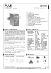
1
DIALOG DUAL
SPECIFICHE
TECNICHE
TECHNICAL
SPECIFICATIONS
DIALOG DUAL
3,3-4-5-6 kVA SINGLE PHASE INPUT/OUTPUT
On Line Double Conversion (VFI) Technology
1
SPEDDXX0205REN
DIALOG DUAL
Table of contents
..1.. OBJECTIVE
3
..2.. DESCRIPTION OF THE SYSTEM
3
..3.. APPLICATIONS
3
..4.. CHARACTERISTICS
4
..5.. REFERENCE STANDARDS
10
> 5.1 Main reference standards
> 5.2 Standards relating to systems and installation
..6.. INSTALLATION INSTRUCTIONS
10
11
12
> 6.1 Tower or Rack installation
> 6.2 Installation of the 5 and 6kVA version
14
15
..7.. SYSTEM BLOCK DIAGRAM
16
> 7.1 Operation of the UPS
> 7.2 Block diagram of the UPS
> 7.3 Operating modes
16
16
18
..8.. INTERFACING
20
> 8.1 Expansion slot
21
..9.. OPTIONS
22
> 9.1 Summary table of options
> 9.2 Replacing the Battery Pack
> 9.3 Communication software
> 9.4 Function of the Powershield2 communication software
..10.. CONTROL / DISPLAY PANEL
22
23
24
25
26
> 10.1 Control and signalling panel
> 10.2 Display panel indications
> 10.3 Measurements display area
> 10.4 Configuration area
26
27
28
29
..11.. UPS CONFIGURATION
30
..12.. VIEWS OF THE UPS
32
> 12.1 Views Ups 3.3 and 4kVA
> 12.2 Views Ups 5 and 6kVA
32
33
..13.. TECHNICAL DATA
34
> 13.1 Models
> 13.2 Back-up expansion modules
> 13.3 Values summary sheet
34
34
34
2
SPEDDXX0205REN
DIALOG DUAL
1
- OBJECTIVE
This technical document has been produced to be used by UPS system designers and installers.
The objective of this document is to provide and illustrate:
-
2
the technical information required to enable you to choose the correct UPS to suit your needs
the information required to set up and configure the system
the information concerning the installation and location of the UPS
the information the UPS displays locally to the user or to the monitoring systems it is connected to
(e.g. control centres, etc.)
a list of the possible options available to configure the UPS to the operators specific requirements.
- DESCRIPTION OF THE SYSTEM
The Dialog Dual range of UPS systems is available in 3.3-4-5 and 6kVA single/single phase models and
uses On Line double conversion (VFI) technology:
The load is constantly powered by the inverter, which supplies a filtered and stabilised sinewave output
voltage and frequency; with the addition of input and output filters which significantly increases the
immunity of the load against mains interference and disturbances.
The technology used offers selectable functions (Economy Mode, Smart Active Mode, Standby/Off) and
intelligent self diagnostics (digital display, RS232 and USB interfaces, communication card slot - network
interface, second serial card, serial duplexer) Dialog Dual is the best solution for protecting sensitive and
vital "mission critical" applications and safety devices (electro medical) with maximum reliability.
3
- APPLICATIONS
=> Personal computers
=> Small computer networks
=> Local Area Networks (LAN)
=> Workstations
=> Servers
=> Point Of Sale Systems (POS)
=> Data centers
=> Industrial PLCs
=> Cash registers
=> Electro medical devices
=> Emergency devices (lights/alarms)
=> Telecom devices
3
SPEDDXX0205REN
DIALOG DUAL
4
- CHARACTERISTICS
Flexibility of installation and use
-
The UPS can be installed as a floor standing tower or 19" rack mount UPS. The front panel digital display
can be removed (using the keys provided) and rotated to suite the installation format.
-
Very low audible noise level (<40bBA) ensures a very low noise impact on the surrounding environment.
This due to the use of high speed IGBT switching technology and PWM controlled ventilation system in
relation to temperature and load applied (>20kHZ, above the audible range).
Personalisation of operation
The user can select the following functions from the front control panel:
-
Economy Mode: used to select Line Interactive (VI) technology to power non-critical loads from the mains
supply. The function can be software programmed or manually set from the UPS.
Smart Active: the UPS selects whether to work in on-line (VFI) or Line Interactive (VI) mode depending on
the stability of the mains supply
Emergency Mode: the UPS can be programmed to work only when the mains fails (suitable for
emergency lighting)
Frequency conversion: 50 or 60Hz
Output voltage selection: 220-230-240V
The software provided enables the customisation of a wide range of functions:
- Auto restart: automatic restart on mains supply return
- Bypass on: when the unit is switched off the loads are automatically routed through the bypass and the
battery is charged
- Shutdown: due to minimum load
- Alarm: end of discharge
- Delay: on start up
- Back up limitation: restricts the back-up time available
- Battery test interval:
- System sensitivity:
Maximum reliability for applications
The system provides a filtered, stable and reliable voltage (On Line double conversion VFI technology in
accordance with European standard IEC62040-3) with filters for suppressing atmospheric and mains borne
disturbances.
The On Line technology provides the maximum protection for the connected loads. The double conversion
stage filters and stabilises the input voltage, and then reproduces it free of any disturbances such as
overvoltages, variations in frequency and voltage, noise, etc.
The IEC62040-3 standard defines this technology as VFI (Voltage and Frequency Independent), meaning
that the output voltage and frequency are completely independent of any variations or disturbances caused
to the incoming mains supply.
High immunity to surges: 4kV in accordance with IEC61000-4-5 - protections against overvoltages have
been provided (VDR). The UPS has been subjected to an overvoltage surge on its input, defined in the
standard (IEC 801-5) as several kV, with a leading edge of 1.2 microseconds and duration of approx. 50
microseconds and maximum energy of 300 Joules
4
SPEDDXX0205REN
DIALOG DUAL
High level of reliability: The digital control system dramatically improves the overall reliability and
efficiency of the UPS; resulting in a reduction in the number of electronic components required, the
microprocessor controls and monitors all of the functions of the UPS from one common control card. The
control card can be used across a number of various systems, even systems in different ranges, thereby
increasing the productivity and reliability of the range.
Low impact on the mains power supply
-
Power factor correction (UPS input factor close to 1):
The UPS absorbs power from the incoming mains supply with a power factor close to 1, even if the systems
supplied by the UPS have a power factor inferior to this. For example, if the UPS supplies a piece of IT
equipment with an input power factor of 0.65, the UPS input power factor will still remain close to 1,
ensuring that any mains supply power factor correction banks are not overloaded.
-
Sinusoidal absorption:
The UPS draws a sinusoidal current from the mains supply, meaning that the system has a very low impact
on the mains supply and, as a consequence, on the other pieces of electrical equipment connected to it.
High reliability and battery availability
-
Hot swapping the batteries:
The Dialog Dual UPS has ‘hot swap’ internal batteries. Replacement can take place whilst the UPS is
powering the load from the mains supply. The UPS uses a dedicated internal battery pack with an
integrated protection system.
When the battery needs to be replaced, the lower front panel can be removed to provide easy access to
the battery pack. Pressing the switch located above the pack informs the UPS to switch onto bypass as the
battery cannot be used whilst it is being changed.
The user can then release and slide out the pack and replace it as necessary by removing and then
reinserting the battery connection.
This operation can be carried out safely due to the integrated protection system and without any disruption
caused to the load connected to the UPS.
-
Automatic battery test:
The UPS carries out battery tests automatically; these tests enable the system to periodically check the
efficiency of the batteries in order to prevent any faults occurring to them. The test does not in any way
compromise the supply to the connected equipment, and given the short duration (seconds), it does not
affect the life or the back-up time of the batteries.
The battery test can also be activated manually from the mimic panel by pressing the “ON” key for several
seconds.
5
SPEDDXX0205REN
DIALOG DUAL
-
Active control (LRCD: Low Ripple Current Discharge)
The LRCD device constantly controls the discharge of the battery system when a mains supply failure
occurs, thus limiting the harmful ac component (ripple at 50 and 100Hz) normally produced during battery
discharge, maintaining a low ripple prevents damage and prolongs the life of the batteries.
Figure 1. ripple current without and with LRCD
- High Hold Up Time (<40msec):
The system can continue to operate normally even during mains supply interruptions of up to 40mS in
duration, this is due to the high hold up time provided by the system. This means that the inverter continues
to power the load during such interruptions without the need to draw energy from the batteries. Battery life is
a function of temperature and the number of charge/discharge cycles experience so this function helps to
optimise the overall battery performance.
- Protection against deep discharge:
The end of battery discharge voltage is automatically increased when low loads are connected to the UPS.
This ensures that deep battery discharges are avoided, as these can dramatically affect the batteries
operational working life.
- Auto Power Off function:
For automatic shutdown of the UPS with minimum loads (<5% of the nominal load):
When operating from the battery, the UPS can be programmed to shut down, if the connected load is less
than 5% of the nominal value. This function (programmable via software) avoids deep discharge of the
battery through the unnecessary powering of very low loads or even with no load over long periods.
- Unlimited expandability of back up time
By means of external battery extension packs which can be supplied with or without their own internal battery
charger to maintain a reasonable recharge time.
6
SPEDDXX0205REN
DIALOG DUAL
- Sinusoidal absorption
The UPS draws a sinusoidal current from the mains supply, meaning that the system has a very low impact
on the mains supply and, as a consequence, on the other pieces of electrical equipment connected to it.
Maximum battery reliability
- Temperature compensated charger:
The system compensates for any variations in temperature whilst recharging the batteries, as temperature
represents the greatest threat to the overall life and performance of the batteries. The recharge voltage is
temperature dependent – the higher the temperature, the lower the recharge voltage will be. This system
ensures that the batteries operate effectively, efficiently and prolongs their life.
- Automatic battery test
The UPS carries out battery tests automatically; these tests enable the system to periodically check the
efficiency of the batteries in order to prevent any faults occurring to them. The test does not in any way
compromise the supply to the connected equipment, and given the short duration (seconds), it does not
affect the life or the back-up time of the batteries.
The period between each test can be configured via the software, or the test can be completely deactivated.
The batteries are also protected against prolonged slow discharge. An electronic device automatically
disconnects the batteries if the discharge period is too long (for example when the UPS is operating on backup either with no load or with very low loads). This protects the batteries from discharging completely, which
inevitably accelerates the ageing process.
Advanced diagnostics:
The control and display panel provides the user with all of the visual (LED and LCD) and acoustic (buzzer)
signals regarding the operational status of the UPS. The panel also enables control, monitoring, diagnosis
and customisation of the UPS through the easy-to-use menu system.
Low consumption
A low power consumption especially in the “Economy Mode” or “Smart Active Mode” functions where
efficiencies of up to 98% can be achieved.
-
Operating modes to reduce consumption
In addition to the On Line operating mode, another four operating modes are provided. These can be
programmed according to user and load characteristic, these being: Economy Mode/Smart Active
Mode/Emergency backup and Standby Off.
-
Economy Mode:
Enables the user to select the Line Interactive (VI) technology, this mode provides power to non sensitive
loads from the incoming mains supply for certain applications. In the event of a mains supply failure
occurring or the incoming voltage or frequency exceeding the pre-determined range, the load is
automatically switched onto the inverter for continued operation. This function can be programmed via the
software.The tolerance range can be programmed using 3 levels of sensitivity (minimum / medium /
maximum) depending on the sensitivity of the connected load.
7
SPEDDXX0205REN
DIALOG DUAL
Smart Active Mode
-
Enables the user to allow the UPS to automatically determine which method of operation (on-line or line
interactive) is most suitable dependent on the quality of the incoming mains supply. If the mains supply is not
within the acceptable limits for both voltage and frequency, the UPS will supply power to the load from the
inverter (on-line). When the mains supply returns to within the acceptable limits, the system will first ensure
that the supply remains stable, before switching the load back onto the mains supply.
During both of these operating modes, the load is powered directly from the mains supply via the bypass.
However, due to the EMI filters in both the input and output, the mains supply is filtered and therefore free of
any electrical disturbances.
If the incoming mains supply fails, the load is supplied directly by the inverter. This function reduces energy
consumption as when the mains supply is present, the inverter is off.
Emergency back-up mode
-
The UPS can function as an emergency stand-by device. This particular operating mode is configurable from
the control panel or the software, and enables the supply to emergency lighting. The UPS output remains off
under normal operating conditions and the batteries are charged. The output only activates when the mains
power supply fails.
The inverter switches on within 320ms in accordance with the current regulations, which stipulates a
maximum delay time of 500ms, the inverter starts up gradually, thus preventing any sudden current surges.
This operating mode enables considerable energy savings, as the inverter is off under normal conditions and
therefore does not consume any energy. In addition, the system does not need to be over-sized, as the
gradual start up of the inverter prevents any current surge problems that might otherwise occur.
Standby-Off operation:
-
The UPS can be configured to power the loads through the bypass when the UPS is powered down. The
battery charger remains active during this period.
Flexibility of use
-
Automatic restart
Auto restart (programmable automatic restart on mains return):
It is possible to program the UPS to automatically restart after the UPS has been switched off for one of the
following reasons. This can be programmed via the software supplied.
Auto restart can be selected for the following scenarios:
-
-
On mains return after the UPS has shut down due to full discharge of the batteries.
On mains return after the UPS has been instructed to power down by remote UPS monitoring and
management software.
Programmed UPS auto shutdown if Auto Power Off has been activated due to load removal
Start up from battery (cold start)
The UPS can start up on inverter, even when there is no mains supply available.
-
Standby:
Standby operation can be selected: during this mode the inverter is off and the batteries are charged. The
standby function is automatically activated when the UPS is shut down and is useful when prolong periods of
inactivity occur.
8
SPEDDXX0205REN
DIALOG DUAL
-
Operation as frequency converter:
The UPS can be configured (from the control panel) to function as a frequency converter, therefore when the
input frequency is 50Hz the output frequency can be 60Hz and vice versa. During this mode of operation the
automatic by-pass is deactivated.
-
Frequency auto detection
The UPS can be configured to automatically select the output frequency (50 or 60Hz), by using the input
frequency as its reference (50 or 60Hz).
-
Compact dimensions:
The compact dimensions make it one of the smallest on the market:
-
Thanks to:
microprocessor control
IGBT technology
internal batteries
ventilation, front to rear which eliminates the need for any clearance down either side of the unit.
Low audible noise (<40db(A):
Achieved by:
use of high frequency IGBT technology
electronically controlled ventilation with PWM (Pulse Width Modulation) technology for improved cooling
fan reliability and speed control in relation to the loads applied and internal UPS temperature.
- special design of the magnetic components
-
Advanced Communication
Monitoring software including shut down
Powershield² provides an efficient and intuitive system for controlling and monitoring the UPS, displaying
all of the most important information, such as input voltage, applied load, battery capacity, etc. using a
series of bar charts.
The software is able to provide detailed information even if the UPS has malfunctioned, enabling the user
to find out why the fault has occurred and when.
Powershield² has been developed using a client/server architecture that renders it flexible and easy to use,
with multilingual support and on line help.
The Powershield² software is provided free of charge with an SNMP agent, this version will operate on
Windows 95, 98, 2000, Windows 2003 Server, Me, Xp, NT4.0, Novell, Mac OS, Mac Osx, Mac Os 9.x &
Linux operating systems.
The software enables the user to programme the automatic start-up and shutdown of the system on a
weekly basis.
The UPS is supplied with the following hardware interfaces:
-
RS232 serial port
USB port
isolated contacts interface
network and communications card slot
9
SPEDDXX0205REN
DIALOG DUAL
5
- REFERENCE STANDARDS
> 5.1 Main reference standards
The company quality system has been certified as conforming to ISO 9001 (Certificate No. CERT-0467499-AQ-VEN-SINCERT). This covers all of the procedures, operating methods and controls from the design
stage to production, sales, through to the after sales service support.
This certification guarantees the following aspects to our customers:
− the use of quality materials
− rigorous standards in production and testing
− receptiveness and openness to our customers
− constant support of all our customers
As well as conforming to this certification, the company also produces “state of the art” products, as
dictated by the requirements of the standards quoted below.
The advances that have taken place in Information Technology systems, means that the power systems
used to power them must be able to provide an absolutely precise, and even more importantly, absolutely
reliable source of power. The standards produced by IEC/CENELEC in the IEC/EN62040 series, cover all
aspects of the product: safety, electromagnetic compatibility and performance. In more detail, this series is
divided into the following individual standards:
STANDARDS
EN62040-1:
Uninterruptible power systems (UPS): general and safety regulations
EN62040-1-1:
Uninterruptible power systems (UPS): general and safety regulations for use in areas accessible to the
operator
EN60950 (CEI74-2):
ITE (Information Technology Equipment) safety
EN50091-2:
Uninterruptible power systems (UPS): electromagnetic compatibility regulations.
EN50081-2:
Electromagnetic compatibility (immunity)
IEC61000-4-2:
Immunity: Electro Static Discharge (ESD)
IEC61000-4-3:
Immunity: electromagnetic fields
IEC61000-4-4:
Immunity: transitory overvoltages (BURST)
IEC61000-4-5:
Immunity: lightning overvoltage (Surge)
IEC61000-4-11:
Low frequency interference
EN50141:
Conducted radio interference
EN55022:
Radiofrequency interference
EN62040-3:
Uninterruptible power systems ( UPS ): regulations for performance and testing methods.
10
SPEDDXX0205REN
DIALOG DUAL
EN50171:
Centralized power supply for emergencies (CSS)
IEC146 (CEI22):
Semiconductor electronic converters
IEC529 (CEI70-1):
Degree of casing protection
European Directives
73/23
Low voltage directive requiring obligatory CE marking as from 1/1/97.
This directive safeguards aspects with regard to equipment safety.
89/336
Electromagnetic compatibility directive enforcing the use of the CE marking from 1/1/96. This directive
concerns all issues of immunity and emissions relating to the UPS once installed.
> 5.2 Standards relating to systems and installation
The above product regulations refer specifically to uninterruptible power supply systems. It is these
regulations that manufacturers of uninterruptible power supply systems are obliged to adhere to. However,
with regard to the electrical system, the installer must refer to other standards.
− standard CEI 64-8 ( HD384/IEC60364 )
for electrical systems in general
− standard CEI 64-8/7 variant 2:
for installation in hospital environments
− standard CEI 11-20:
for systems with UPS machines connected to category I or II networks
− standard CEI 17-13 ( EN60439-1 )
relating to control equipment
− standard CEI 21-6/3 (EN50272):
for battery installation
− CEI 20:
for electrical cables
11
SPEDDXX0205REN
DIALOG DUAL
6
- INSTALLATION INSTRUCTIONS
Equipment and accessories provided with UPS 3.3 and 4kVA
The UPS system is supplied with the following items:
UPS
2 plastic covers
(top panels)
2 plastic keys
to release the front panel display
Power supply cable
(Schuko/UK plug –IEC 16A socket)
2 IEC 10A connection cables
RS232 serial cable
IEC 16A loose plug
User manual + CD-ROM with software
User's
m an u al
Note the UPS is also supplied with a rack enclosure
handles kit as shown on the next page
12
SPEDDXX0205REN
DIALOG DUAL
Equipment and accessories provided with UPS 5 and 6kVA
The UPS system is supplied with the following items:
UPS
3 plastic covers
(top panels)
2 cable glands
2 plastic keys
to release the front panel display
Cable end ferrules
RS232 serial cable
Rack handles kit
User manual + CD-ROM with software
User's
manual
13
SPEDDXX0205REN
DIALOG DUAL
> 6.1 Tower or Rack installation
TOWER VERSION
Once removed from the packaging, the UPS is ready for installation in a tower configuration.
All that is needed to complete this configuration is to mount the plastic covers provided (two for the 3.3 and 4kVA
and three for the 5 and 6kVA) on the top part of the UPS, following
the instructions below:
The 2 covers have an interlocking system:
locate the specific cover mounting holes on the top part of the UPS
and, with the utmost care, push in the covers gently, as shown in the
figure opposite.
Note: as the covers are exactly the same, they can be mounted on
either side (front or back) of the top part of the UPS.
5 and 6kVA shown above
RACK VERSION
The sequence of operations required to convert the UPS into the rack version is described below.
1 - First remove the 4 feet from the base of the UPS.
Put the UPS into a horizontal position and with a
small slotted screwdriver carefully lift the pin at
the centre of the foot. Once it has been lifted,
remove the foot from the base of the UPS.
Repeat the same operation for the remaining
feet. The exact sequence to follow is shown
opposite:
1
2 - Once all of the feet have been removed, the display mask must then be rotated.
Insert the keys provided in to the release slots located at the sides of the display
mask and exert enough gentle pressure to release the mask from the UPS, as
shown in the figure opposite.
3 - Rotate the mask through 90° to suit the layout and carefully replace it in the UPS
housing until a slight click is heard.
4 - Rotate the UPS 90° as required.
5 - At this point, with the UPS in a horizontal position, fasten the handles to the sides
of the UPS with the specific screws as shown in the figure opposite. Note:
handles and screws are included in the handles kit)
NOTE: The UPS is compatible for mounting in standard rack cabinets of 600mm x
800mm or more (in width).
Support brackets (guides with L-shaped support), available as options or a shelf, must
be used in the rack installation due to the weight of the batteries. It is recommended
that you install the UPS in the lower part of the rack cabinet for the same reason.
14
SPEDDXX0205REN
2
DIALOG DUAL
> 6.2 Installation of the 5 and 6kVA version
For the mains input and load connections follow the instructions as below:
1. Install a 32A magnetic-thermal switch (MCB) with a type B or C trip curve
upstream of the equipment.
2. The terminals to be used for the connection of the input and output cables are
located inside the IN/OUT connections drawer. Undo the screw securing the
connections drawer located on the right-hand side of the drawer (see figure
opposite).
3. Pull the drawer out as much as is needed to access the terminals (see figure
opposite). WARNING: the drawer has a locking system to prevent it being pulled
out completely. Do not try to remove the drawer completely.
4. Use 3-core cables with a cross section of 4mm2. With reference
to the figure shown opposite:
- Insert the cable from the 32A magnetic-thermal switch into cable
guide P1 (input line).
- Insert the cable from the load into cable guide P2 (output line).
- Strip the cables observing the measurements provided.
- Insert the stripped end in the terminals provided.
5. Connect the wires to the relative terminals
strictly following the instructions set out below:
B y- P a s s
M a n ut e n z i o n e R emoto
Remote Maintenance
By-Pass
Input cable
a - Ensure that the magnetic-thermal switch
upstream is open.
b - Connect the earth wire to terminal 3.
c - Connect the neutral wire to terminal 1.
d - Connect the phase wire to terminal 2.
P2
P1
8
7
6
5
4
Output cable
a - Connect the earth wire to terminal 4.
b - Connect the neutral wire to terminal 5.
c - Connect the phase wire to terminal 6.
3
2
6. Ensure that a jumper is connected at terminals
7 and 8; this is needed for the UPS to operate
correctly.
1
7. Secure the cable glands to the flange close the drawer and secure it with the screw previously removed.
15
SPEDDXX0205REN
DIALOG DUAL
7
- SYSTEM BLOCK DIAGRAM
> 7.1 Operation of the UPS
Description of the UPS
The purpose of a UPS is to provide a perfect power supply voltage to the equipment connected to it,
regardless of the quality and stability of the incoming mains supply. Once connected and switch on, the
UPS generates a sinusoidal alternating voltage with stable amplitude and frequency, regardless of any
surges and/or variations present on the mains supply.
Whilst the UPS draws energy from the incoming mains supply, the batteries are charged. The
microprocessor continuously monitors the amplitude and frequency of the incoming mains voltage, the
amplitude and frequency of the voltage generated by the inverter, the applied load, the internal
temperature and the state battery charge and efficiency.
The block diagram for the 3.3 and 4kVA UPS is shown below (see Fig. 5) followed by a description of the
individual components. For the 5 and 6kVA UPS block diagram (see Fig. 6) shown later.
> 7.2 Block diagram of the UPS
Fig. 5 Block diagram of the 3.3-4kVA
KEY:
1) Input protection (restorable thermal protection).
2) EMI input filter + back-feed protection:
Input filter for protecting the UPS and load against any electromagnetic disturbances.
Back-feed protection: intervenes when the mains power supply fails, therefore isolating the UPS from the
input socket to prevent any back feed to the mains power supply. This protection is required to prevent any
voltage from returning to the supply, which could put the operator at risk whilst carrying out maintenance
work.
16
SPEDDXX0205REN
DIALOG DUAL
3) Input fuse:
The input fuse is discriminated with respect to the re-settable input fuse (1): a fault occurring to the
rectifier/booster will open this protection before the thermal input fuse intervenes, ensuring that the power
supply to the connected load is not interrupted, as the by-pass line will remain powered.
4) AC/DC input stage (PFC):
When the mains power supply is present, this converts the mains alternating current (AC) into a direct
current (DC) whilst controlling the power factor. If the mains power supply fails, it increases the voltage
from the battery to an appropriate voltage level to power the inverter stage.
5) DC/AC Inverter stage:
Converts the direct current (DC) into alternating current (AC) to supply the load.
6) Automatic bypass:
The automatic bypass automatically switches the UPS output onto the input mains in the event of an
overload and/or inverter fault.
7) Inverter switch:
Transfers the load to the bypass supply.
8) Battery pack:
Maintenance-free, sealed lead acid batteries: Supplies power to the inverter to support the load when the
incoming mains power supply fails.
9) Battery charger:
A DC-DC converter which converts the output voltage from the rectifier/booster to a suitable level to
recharge the batteries, it is deactivated when the mains power supply fails.
10) Battery protection:
Battery to UPS protection fuses
11) Interface card:
An RS232, a USB (Universal Serial Bus) interface and isolated contacts are supplied as standard. The UPS
automatically detects whether the RS232 or USB port has been selected for remote communication.
12) Network adapter and communication card slot:
The communications card slot can be used to insert various interface card: for example a second RS232
serial card, an SNMP interface for communication over the computer network, an RS232 serial interface
duplexer or a volt free contact card.
13) Display:
The display panel provides the user with visual (LED + LCD) and acoustic (buzzer) signals relating to the
status of the UPS. The panel also enables the user to control and customise the operation of the UPS.
14) Output sockets
1 x IEC standard 16 A socket + 2 x 10 A IEC sockets are available at the rear of the unit for load
connection.
17
SPEDDXX0205REN
DIALOG DUAL
Fig. 6 Block diagram of the 5-6kVA
> 7.3 Operating modes
Operating modes:
The default operational mode that provides maximum protection to the load is the ON LINE mode. During this
mode the load is supplied with a sinewave that is stabilised and regulated in terms of voltage and frequency, the
waveform is independent of the incoming mains supply (VFI technology) and controlled by the digital
microprocessor.
The following other modes can also be selected:
ECONOMY (LINE INTERACTIVE)
SMART ACTIVE (shown on the display as “SMART”)
STANDBY OFF (shown on the display as “STBYOFF”)
During economy mode the load is normally powered via the bypass, in order to optimise the operating efficiency. If
the incoming mains supply exceeds the predefined operating range (voltage or frequency), the UPS switches to
battery operation.
If the user cannot decide which operating mode is the most suitable for the application (ON LINE or ECONOMY),
this decision can be left to the UPS by selecting the SMART ACTIVE mode. In this mode, the UPS automatically
decides which mode to use based upon an assessment of the quality and availability of the incoming mains supply.
18
SPEDDXX0205REN
DIALOG DUAL
The STANDBY OFF mode is used for emergency lighting applications when the load is not powered until the
incoming mains supply fails, at which point the output from the UPS is switched on.
Status of the
mains supply
and loads
Comments
Mains present, loads
not powered*
The UPS is in a condition of minimum power consumption because the booster and the
inverter are switched off. The microcontroller is powered and carries out supervision and selfchecking functions, the batteries are charging and everything is ready for the UPS to be started
up. The UPS only operates in stand-by mode from the batteries if it has been set for
programmed start up via software.
Operating
mode
STANDBY
ON-LINE
ON-LINE
ON-LINE
LINE-INTERACTIVE
LINE-INTERACTIVE
LINE-INTERACTIVE
Mains present, loads
powered from the
inverter with energy
drawn from the
mains
Mains present, loads
powered from bypass
Mains absent, loads
powered from the
inverter with energy
drawn from the
batteries
Mains present, loads
powered from
bypass
Mains present, loads
powered from the
inverter with energy
drawn from the
mains
Mains absent, loads
powered from the
inverter with energy
drawn from the
mains
This is the normal state for this operating mode. The loads are powered from the inverter with
a frequency and voltage stabilised waveform. The battery chargers ensure that the batteries
are charged.
The UPS goes into this state on start up from the mains (before passing to the inverter), or
when a distorting load is applied or there is a temporary overload
The UPS goes into this state when the mains fails (Black out) or goes out of the admitted range
(overvoltage or undervoltage). The loads are powered from the inverter with a frequency and
voltage stabilised waveform and energy is received from the batteries.
This is the normal state for this operating mode. The loads are powered from the bypass
through the internal EMI filters when the mains returns within the set voltage and frequency
ranges; the batteries are charged.
The UPS goes into this state when the bypass (mains) voltage and frequency go out of the set
range.
The UPS goes into this state when the mains fails (Black out) or goes out of the admitted range
for operation from the mains (overvoltage or undervoltage)
* if the StandBy Off function, which provides power to the load when the unit is switched off by means of the Bypass
circuit, is not set.
Emergency Power Off (EPO) (version 5 and 6kVA)
This isolated input is used to switch off the UPS remotely in an emergency. Any remote “Emergency Power Off”
(EPO) switch that is normally closed must be connected to the connector located at the back of the UPS.
The UPS is supplied with the EPO terminals short circuited: remove the short circuit if this contact is to be connected
to the auxiliary of a remote emergency switch.
The EPO circuit is self-powered with SELV type circuits. No external power supply voltage is therefore required.
When it is closed (normal condition) there is a current of 10mA max.
Programmable auxiliary socket (PowerShare - 5 and 6kVA versions)
The UPS is provided with two output sockets which can be programmed to switch off or remain on during a mains
supply failure – PowerShare. The events that trigger the PowerShare can be user-selected using the UPSTools
configuration software (see paragraphs Configuration software and UPS Configuration).
It is possible for example to select switch off after a certain time of operation from battery, on reaching the end of a
battery discharge pre-alarm threshold, or during an overload condition.
19
SPEDDXX0205REN
DIALOG DUAL
8
- INTERFACING
Communication ports
The UPS is supplied with an RS232 and USB serial interface. The serial interface must be supplied with a +/- 12V
isolated power supply.
The serial interface has a female sub-D 9-pole connector that carries the signals for the interface (fixed baud rate
=1200) and three auxiliary opto-isolated contacts with the following pin configuration:
Pin
7
2
3
8
9
Name
+12V
TX
RX
BL
BW
1
5
ALARM
GND
Function
Notes
Serial transmission line
Serial receive line
Auxiliary opto-isolated contact
Auxiliary opto-isolated contact
Auxiliary opto-isolated contact
Signals end of discharge
Signals operation from battery or mains
fail
Signals operation from by-pass
In addition to the USB and serial port, the UPS also has an expansion slot located at its rear, where various types of
interfaces can be inserted. For example a second serial/USB, serial multiplexer. The signals sent to the slot are
shown in the table below.
PIN
NAME
TYPE
FUNCTION
NOTES
1
Not used
2
Not used
3
ALARM
UD Signals UPS fault
4
INIT
UD System initialisation
5
REMOTE ON
ID Remote UPS start up
6
Not used
7
Not used
8
REMOTE OFF
ID Remote UPS shutdown
9
INVOFF
ID Inverter shutdown and passage onto bypass
10
BL
UD Signals end of discharge
11
BW
UD Signals operation from battery
12
BY-PASS
UD Signals operation from bypass
13
DCD2
ID DCD secondary serial line
14
DTR2
UD DTR secondary serial line
15
Not used
16
+5V
PWR
17
Not used
18
+12V
PWR
19
Not used
20
Not used
21
Not used
22
RX2
ID RX secondary serial line
23
TX2
UD TX secondary serial line
24
GND
PWR
25
Not used
26
Not used
Where UD = digital output, ID = digital input, PWR = power signal.
The communication protocol used for the remote control of the UPS via the serial port is: PSGPSER.
20
SPEDDXX0205REN
DIALOG DUAL
> 8.1 Expansion slot
The UPS has an expansion slot for a wide range of interface cards (see figure opposite):
UPS
•
Second RS232 port
•
Serial port duplexer
•
Ethernet network agent with TCP/IP, HTTP and SNMP protocol
•
RS232 + RS485 port with JBUS / MODBUS protocol
•
Volt free contact signalling relay card
21
SPEDDXX0205REN
DIALOG DUAL
9
- OPTIONS
> 9.1 Summary table of options
Description
Battery expansion pack for DLD 3300VA
rack/tower version
(9 12V-7Ah batteries)
Battery expansion pack for DLD 3300VA
rack/tower version (9+9 12V-7Ah batteries
without battery charger)
Battery expansion pack for DLD 3300VA
rack/tower version (9+9 12V-7Ah batteries with
battery charger)
Battery expansion pack for DLD 4000VA
rack/tower version
(9 12V-7Ah batteries)
Battery expansion pack for DLD 4000VA
rack/tower version (9+9 12V-7Ah batteries
without battery charger)
Battery expansion pack for DLD 4000VA
rack/tower version (9+9 12V-7Ah batteries with
battery charger)
Battery expansion pack for DLD 5000VA
rack/tower version
(16 batteries 12V-7Ah without battery charger)
Battery expansion pack for DLD 5000VA
rack/tower version
(16 batteries 12V-12Ah without battery charger)
Battery expansion pack for DLD 5000VA
rack/tower version
(16 batteries 12V-12Ah with battery charger)
Battery expansion pack for DLD 6000VA
rack/tower version
(16 batteries 12V-7Ah without battery charger)
Battery expansion pack for DLD 6000VA
rack/tower version
(16 batteries 12V-12Ah without battery charger)
Battery expansion pack for DLD 6000VA
rack/tower version
(16 batteries 12V-12Ah with battery charger)
Mains adapter pack on slot
Communication software
Interface card, second serial card
Handles kit (for rack version)
Dimensions (HLD) mm
Weight (Kg)
455x175x520
30
455x175x520
50
455x175x520
50
455x175x520
30
455x175x520
50
455x175x520
50
455x175x660
60
455x175x660
80
455x175x660
80
455x175x660
60
455x175x660
80
455x175x660
80
Battery expansion pack:
This is used to extend the UPS back up time. It is supplied in a metal cabinet to match the UPS and is
available without or with an additional battery charger to help maintain reasonable recharge times.
22
SPEDDXX0205REN
DIALOG DUAL
> 9.2 Replacing the Battery Pack
As mentioned in the introduction, the UPS comes with dedicated battery packs (1 in the 3.3 and 4 kVA and 2 in the
5 and 6kVA) that can be safely and easily ‘hot-swap’ replaced,
VERSION 3.3 - 4kVA
VERSION 5 - 6kVA
The battery pack is located behind the front panel of the
UPS. Hold the panel centrally from the sides and gently
pull it outwards as shown in the figure at the side.
Press the circuit breaker located under the front panel
putting it into position “II” as shown in the figure opposite.
When the breaker is in this position, the load is powered
from the bypass and the display should show the message
C02. If during the replacement procedure you should
forget to switch the breaker back to position “I”, this will
be done automatically when the front plastic cover is
reconnected.
The battery pack is connected to the rest of the UPS via a
cable with terminal. Referring to the figure on the left
hand side for the 3.3 and 4kVA version:
press the 2 tabs at the sides of the terminal ( A ) and
remove it by gently pulling it upwards. Use your thumbs to
press the 2 fastening hooks ( B ) together and, keeping
them pressed, insert your index finger in the slot
underneath the connector ( C ).
Referring to the figure on the right hand side for the 5 and
6kVA version:: take hold of the connector ( A ) and
remove it by gently pulling. Undo the two screws securing
the battery pack to the UPS ( B ) and take hold of the
handle ( C ) for removal.
Holding the position described in the previous step,
remove the battery pack by pulling it outwards, as shown
in the figure at the side.
Insert the new battery pack in the compartment and slide it in until it engages with the UPS. Reconnect the cable
with terminal to the connector, put the circuit breaker back to position “I” and close the front panel. Check that the
display has returned to normal display mode.
If the installation procedure is not performed correctly, or if some of the sections are missed out (such as
reconnecting the battery connector), the display will show an alarm message
23
SPEDDXX0205REN
DIALOG DUAL
> 9.3 Communication software
MAIN FEATURES
1) Sequential shut-down with defined priority:
PowerShield2 enables the user to shutdown the network without having to individually switch off each PC or
server, and before doing so, Powershield² will save the work that was being done regardless of the application
that was being used. The user may also define their own shutdown procedure and also prioritise the shutdown
of critical components within the system (such as vital and non vital servers).
2) Multiplatform compatibility:
PowerShield2 provides the user with a standard control and monitoring capability, using TCP/IP communication
protocol.
This enables the user to monitor computers that use different operating systems from a single console. For
example, not only could the user monitor a UNIX server from a PC with Windows 98, the user could also
connect to UPS systems situated in different locations by using either a dedicated network (intranet) or the
Internet.
3) Events scheduling:
PowerShield2 enables the user to define their own shutdown/switch off and on procedures, for the systems that
are connected to the UPS. Not only does this noticeably increase the degree of security of the system, it also
enables the user to make significant energy savings.
4) Management of messages:
PowerShield2 keeps the user constantly informed of the status of the UPS, whether locally or by sending
messages to users connected to the network. It is also possible to create a list of the people who will receive
messages by e-mail, fax and SMS should a fault or sudden blackout occur.
5) Integrated SNMP agent:
PowerShield2 contains an integrated SNMP agent for managing the UPS via SNMP. This agent is able to send
all of the information regarding the UPS and is capable of generating traps using the RFC 1628 MIB standard.
This enables the user to control the UPS using SNMP compatible workstations such as HP Open View, Novell
Managewise and IBM NetView.
OPERATING SYSTEMS SUPPORTED (Powershield² FULL version )
-
Windows 95, 98, Me, NT 4.0, Win 2000, Win 2003 Server, XP.
Novell Netware 3.x, 4.x, 5.x, Intra NetWare
IBM OS/2 Warp and Server,
Mac OS, 9.X, OSX
The most commonly available UNIX systems such as:
IBM AIX, HP UNIX, SUN OS SPARC, SUN Solaris INTEL and SPARC, SCO Unix and UnixWare,
Siemens SINIX, Silicon Graphic IRIX, Compaq True64 UNIX and DEC UNIX, Linux, BSD UNIX and FreeBSD
UNIX
24
SPEDDXX0205REN
DIALOG DUAL
> 9.4 Function of the communication software
1) Graphic monitoring of UPS status
PowerShield2 is the easy to use yet powerful program that enables the user to monitor and control the UPS systems.
There are various graphical versions including Windows, Java, OS/2 and MacOS.
2) Version for MacOS
The PowerShield2 software is the only UPS control and shutdown software available for the Macintosh that has a
client-server architecture.
Enabling the user to access the Windows, Novell, IBM OS/2 and the most commonly available UNIX operating
systems, when using a TCP/IP network.
It also enables the user to support the NetMan series network agents to control the UPS via a network, and
furthermore, comes with multilingual support.
3) Detailed display with all UPS values
PowerShield2 provides all the data required to make an accurate and swift assessment of the UPS operation and
status.
4) UPS block and operating diagrams
PowerShield2 displays a block diagram of the UPS, thus providing the user with conceptual information as to the
status of the system.
5) Saving the event history log and graphic display of the main values
All of the events regarding the operation of the UPS are saved and recorded, thus allowing the user to monitor such
data as the input voltage, applied load or the remaining back-up time available from the batteries.
6) Alarm notification via e-mail and SMS
It is possible to configure PowerShield2 to automatically notify of an alarm via an e-mail or SMS message.
7) Programming UPS controls
Enables the user to program all of the commands that would normally be carried out manually, to be performed
automatically, for example: shutting down or switching the servers back on, UPS battery test, etc.
25
SPEDDXX0205REN
DIALOG DUAL
10
- CONTROL / DISPLAY PANEL
> 10.1 Control and signaling panel
View of the display
11
9
10
8
1
2
Display
LCD
3
4
5
6
7
1
Regular operation
7
Configuration area
2
Operation from mains
8
Service intervention
3
Operation from battery
9
Timer
4
Load on bypass
10
Measurements display
5
Battery level indicator
11
Stand-by / fault
6
Load level indicator
The upper part of the front panel houses a display with yellow/green reversed backlighting. The layout of the
display, designed to Riello UPS specifications, can be divided into 3 basic areas.
The first area, consists of the icons on the left and a red triangle, this area is dedicated to the UPS status (on mains,
on battery, on bypass, normal operation and alarm).
The second area comprises of two bar graphs, numerical indications and the upper part of the central area is
reserved for measurements. The two bar graphs show the load and percentage of battery charge, while the
numerical indications show the input frequency and voltage, output frequency and voltage, estimated battery back
up time (mins), estimated battery charge level (%), battery voltage, load in percentage and the current and
temperature of the internal heat sinks. Each of these indications has a name and unit of measurement; press the
middle button under the display to scroll from one to the other.
The same figures are also used to indicate alarm or lock up codes.
26
SPEDDXX0205REN
DIALOG DUAL
The last area on the right consists of the set-up area which is accessed by pressing down the middle button for
several seconds. The output voltage and frequency and the operating mode can be changed directly from the front
panel (removing the need to use dip switches). The visual signals can be accompanied by a audible buzzer that
provides an acoustic alarm in the following cases:
-
on start up / shutdown
when the output is synchronized with the input
transfer from inverter to bypass and vice versa
during operation from the battery
during overload
during a fault or lock
> 10.2 Display panel indications
This section describes in detail all the information that can be shown on the LCD display. All the information
displayed can be divided into three main groups:
UPS status indicators
Measurements display area
Configuration area
UPS status indicators
ICON
STATUS
DESCRIPTION
Constant
Indicates a fault
Flashing
The UPS is in stand-by state
Constant
Indicates normal operation
Constant
The UPS is operating from the mains
Flashing
The UPS is operating from the mains, but the output voltage is not
synchronised with the mains voltage
Constant
The UPS is operating from the battery. When it is in this state the UPS
emits an audible signal (beep) at regular intervals of 4 sec.
Flashing
End of discharge pre-alarm. Indicates that the battery back up time is
coming to an end. In this condition the UPS emits a beep at regular
intervals of 1 sec.
Constant
Indicates that the loads connected to the UPS are powered from the
bypass
27
SPEDDXX0205REN
DIALOG DUAL
Dynamic
If the UPS is operating from the mains, it indicates the battery charge
status (%). If the UPS is operating from the battery, it indicates the
battery back up time (%)
Dynamic
Indicates the % of load applied to the UPS with respect to the nominal
value
Flashing
A Service is required (service centre).
Contact your local Riello UPS service center.
Constant
Indicates that the timer is activated (UPS auto-start up and/or autoshutdown). The timer can be activated/deactivated via the software
provided
> 10.3 Measurements display areas
The most important UPS measurements can be shown in sequence on the display. When the UPS is started up, the
display shows the value of the mains voltage. To go on to a different display press the “SEL / SET” button
repeatedly until the required measurement is displayed.
If a fault / alarm (FAULT) or a lock (LOCK) should occur, the type and corresponding alarm code is automatically
shown on the display.
Some examples are shown below:
GRAPHIC EXAMPLE
(1)
DESCRIPTION
GRAPHIC EXAMPLE
DESCRIPTION
Mains voltage
Total battery voltage
Mains frequency
Percentage of the
applied load
Voltage output from the
UPS
Current absorbed by the
load
Frequency of the output
voltage
Temperature of the
cooling system for the
UPS internal electronics
Estimated battery back
up time
Fault / Alarm (2): the
corresponding code is
displayed
Percentage of battery
charge
Lock (2): the
corresponding code is
displayed
28
SPEDDXX0205REN
(1)
DIALOG DUAL
> 10.4 Configuration area
The configuration area groups together the main UPS operating parameters and displays its current status. The
parameters contained in this area can be changed directly from the display panel.
CONFIGURABLE PARAMETERS:
Frequency: Output voltage frequency
Frequency
Voltage: Output voltage
Voltage
Mode: UPS operating mode
Mode
The figure opposite shows the setup display area (configuration
area) showing the three configurable parameters.
HOW TO CHANGE THE SETTINGS:
To access the configuration area, hold the “SEL / SET” button down for at least 2 sec.
The word “SET” will light up and an arrow ( d ) will appear to the left of Frequency.
The arrow shows the selected setting. To select a different parameter press the “SEL / SET’ button.
To change the selected item, press the “ON” button.
To exit from the configuration area, hold the “SEL / SET” button down for at least 2 sec.
POSSIBLE SETTINGS
Frequency:
d 50 Hz
d 60 Hz
d Off (frequency auto-sensing)
Voltage:
d 220 V
d 230 V
d 240 V
Mode:
d ON LINE
d ECO
d SMART
29
SPEDDXX0205REN
d STBYOFF
DIALOG DUAL
11
- UPS CONFIGURATION
The following table shows all the possible configurations available to customise the UPS to the user’s requirements.
KEY:
=
Indicates that the configuration can be changed from the display panel as well as by
the configuration software provided.
=
Indicates that the configuration can only be changed via the configuration software
provided.
FUNCTION
DESCRIPTION
Output
frequency
To select the nominal
output frequency
Output voltage
To select the nominal
output voltage
To select one of the 4
Operating mode
different operating
modes
DEFAULT
POSSIBLE CONFIGURATIONS
•
•
•
50 Hz
60 Hz
Auto: automatic sensing from
the input frequency
•
•
•
•
220V
230V
240V
220 - 240 in 1V steps
(only via the software)
ON LINE
•
•
•
•
ON LINE
ECO
SMART ACTIVE
STAND-BY OFF
Auto
230V
Start up delay
Delay before
automatic restart on
the mains returns
5 sec.
•
•
Disabled
1 - 255 in 1 sec. steps
Shutdown due to
minimum load
Automatic shutdown
of the UPS when
operating from the
battery if the load is
less than 5%
Disabled
•
•
Enabled
Disabled
Disabled
•
•
Disabled (full battery discharge)
1 - 65000 in 1 sec. steps
Back up time
limit
End of
discharge alarm
Maximum time of
operation from the
battery
Estimated remaining
back up time for the
end of discharge
alarm
3 min.
1 - 255 in 1 min. steps
30
SPEDDXX0205REN
MODE
DIALOG DUAL
FUNCTION
DESCRIPTION
PREDEFINED
POSSIBLE CONFIGURATIONS
Battery test
Time interval between
the automatic battery
test
40 hours
•
•
Disabled
1 - 1000 1 hour steps
Alarm threshold
for maximum
load
Selects the user
overload limit
Disabled
•
•
Disabled
0 - 103 in 1% steps
Display
brightness
Selects the level of
brightness of the LCD
display
Maximum
Acoustic alarm
Selects the operating
mode of the acoustic
alarm
Low
Minimum ÷ Maximum in 20 steps
•
•
Normal
Low: does not sound for
momentary bypass intervention
ADVANCED FUNCTIONS
Input frequency
tolerance
Selects the allowed
input frequency range
for the transfer to
bypass and for
synchronisation of
the output
± 5%
Bypass voltage
thresholds
Selects the allowed
voltage range for the
transfer onto bypass
Low: 180V
High: 264V
Bypass voltage
thresholds for
ECO
Sensitivity of
intervention for
ECO
•
•
•
•
± 0.25%
± 0.5%
± 0.75%
± 1 - ±10 in 1% steps
Low: 180 - 200 in 1V steps
High: 250 - 264 in 1V steps
Selects the allowed
voltage range for
Low: 200V
Low: 180 - 220 in 1V steps
High: 253V
High: 240 - 264 in 1V steps
operation in
Economy mode
Selects the sensitivity
•
Low
of intervention during
Normal
•
Normal
operation in
•
High
Economy mode
Power supply of
the load in
standby
Bypass operation
Power supply of the
load on bypass with
UPS switched off
(standby state)
Selects bypass line
operating mode
Disabled
(load NOT
powered)
Normal
•
•
•
•
•
31
SPEDDXX0205REN
Disabled (not powered)
Enabled (powered)
Normal
Disabled with input / output
synchronisation
Disabled without input / output
synchronisation
MODE
DIALOG DUAL
12
- VIEWS OF THE UPS
> 12.1 Views UPS 3.3 and 4kVA
32
SPEDDXX0205REN
DIALOG DUAL
> 12.2 Views UPS 5 and 6kVA
Release slots
Rotatable display
Manual bypass
switch
Main switch
Battery pack
Removable front
panel
Cable with terminal
Cable with terminal
Battery pack
(front panel removed)
(front panel fitted)
Front view
Fan
Battery expansion connector
COMMUNICATION SLOT
RS232 communication port
IEC 10A PowerShare sockets
USB communication port
PowerShare sockets thermal breaker
IN / OUT connections box
Emergency Power Off.
(EPO)
Rear view
33
SPEDDXX0205REN
DIALOG DUAL
13
- TECHNICAL DATA
> 13.1 Models
Dialog Dual Model
MODEL
Dialog Dual DLD 3300VA tower
Dialog Dual DLD 3300VA rack
Dialog Dual DLD 4000VA tower
Dialog Dual DLD 4000VA rack
Dialog Dual DLD 5000VA tower
Dialog Dual DLD 5000VA rack
Dialog Dual DLD 6000VA tower
Dialog Dual DLD 6000VA rack
POWER
3300VA/2300W
3300VA/2300W
4000VA/2400W
4000VA/2400W
5000VA/3500W
5000VA/3500W
6000VA/4200W
6000VA/4200W
BACK UP TIME ( min )
12
12
10
10
10
10
8
8
DIMENSIONS (HLD) mm
455x175x520
4Ux483x520
455x175x520
4Ux483x520
455x175x660
175 (4U)x483x660
455x175x660
175 (4U)x483x660
> 13.2 Back-up expansion packs
For types and back up times of the Dialog Dual models refer to the Riello Ups's price list.
> 13.3 Values summary sheet
MODELS
3300
4000
5000
6000
INPUT
Input phases
Nominal voltage
Maximum input voltage without battery
Minimum input voltage without battery (applied load
100%)
Minimum input voltage without battery (applied load
50%)
Nominal frequency
Maximum current
1
220-230-240Vac single-phase
276Vac single-phase
164Vac single-phase
84Vac single-phase
50-60Hz +/-5 Hz
15 A
34
SPEDDXX0205REN
16 A
25 A
30 A
DIALOG DUAL
MODELS
Nominal current
Power factor
Current distortion (THDi)
Input protection
3300
11 A
Bypass protection
Back up time in minutes
No. of batteries
Nominal battery voltage
Type of battery
Configuration of the batteries
Type of recharge
Recharge current
Recharge time
Intervention time (mains failure)
6000
22 A
>0.98
Resettable thermal
protection 16A
Overvoltage protection
(VDR)
<6%
Resettable thermal
protection 16A
Overvoltage protection
(VDR)
40ms
BY-PASS
Overvoltage protection
(VDR)
Overvoltage protection
(VDR)
≥ 35ms
264V single-phase
180V single-phase
± 5% of the selected frequency (configurable)
Resettable thermal
Resettable thermal
Overvoltage protection
Overvoltage protection
protection 16A
protection 16A
(VDR)
(VDR)
Overvoltage protection
Overvoltage protection
(VDR)
(VDR)
BATTERY
12’
10’
18’
13’
9
16
108Vdc
192Vdc
Lead acid, maintenance free
High efficiency
In series
Single level (floating)
1A
6-8h
Zero
Nominal battery connector voltage
108Vdc
35
SPEDDXX0205REN
5000
18 A
<7%
“Hold up” time
Maximum acceptable voltage for switching onto
mains
Minimum acceptable voltage for switching onto
mains
Frequency tolerance accepted for switching
4000
12 A
192Vdc
DIALOG DUAL
MODELS
Nominal power supplied
Recharge voltage
End of discharge voltage
Stability of the battery voltage (fully charged)
Battery protection
3300
2600
4000
2700
5000
3400
122V
85,5V
6000
4070
217V
152V
0.7%
Fuse 35AGF
Fuse 35AGF
Fuse 35AGL
Fuse 35AGL
OUTPUT
Nominal voltage
Waveform
Frequency
Operation as frequency converter
Current crest factor (in accordance with standard
EN62040-3)
Nominal power (VA)
Nominal power (W)
Static variation
Dynamic variation (with impact of the load from 0 to
100%)
Variation of the output frequency with mains absent
Speed of frequency variation (Hz/s)
Restored voltage after dynamic variation
Voltage distortion (linear load)
Voltage distortion (non linear load)
220/230/240Vac selectable
Sinusoidal
50/60Hz auto-sensing or selectable
YES (with batteries)
3:1
3300
2300
6000
4200
<5%
<0.1%
<1
<20ms
<2%
<6%
<5%
OVERLOAD TIMES
Overload on battery
60’’
60’’
4’’
4’’
0.5’’
0.5’’
1.5In for 0.5’’
1.5In for 0.5’’
Overload from the bypass
36
SPEDDXX0205REN
5000
3500
±1%
100%<Load<=110%
110%<Load<=150%
Load>150%
Maximum effective inverter current
4000
2400
<5%
60’’
4’’
0.5’’
60’’
4’’
0.5’’
1.5In for 0.5’’
1.5In for 0.5’’
DIALOG DUAL
MODELS
100%<Load<=110%
110%<Load<=150%
Load>150%
3300
120’’
4’’
1’’
4000
120’’
4’’
1’’
5000
120’’
4’’
1’’
6000
120’’
4’’
1’’
85%
85%
88%
88%
89%
89%
91%
91%
90%
90%
92%
92%
90%
90%
92%
92%
98%
98%
98%
98%
SUNDRY
AC/AC performance (Double conversion operation) 25% of load
AC/AC performance (Double conversion operation) 50% of load
AC/AC performance (Double conversion operation) 75% of load
AC/AC performance (Double conversion operation) 100% of load
AC/AC performance (Line Interactive operation)
Maximum permanent operating temperature
Operating ambient temperature
Recommended operating temperature
(for the batteries)
40°C
40°C
20/25°C
Humidity
<90% non condensing
Protections
Battery overvoltage - Inverter overvoltage (on peak) - Inverter voltage out of tolerance
Back feed protection (input supply relay to isolate the
UPS input with mains absent)
YES
NO
Safety compliance
EN62040-1-1
Directives 73/23/EEC and 93/68/EEC
EMC compliance
EN50091-2 cl. A, directive 89/336/EEC
Immunity to surges
IEC61000-4-5
(protections for overvoltage (VDR)
Noise
<40dB(A)
37
SPEDDXX0205REN
<45dB(A
DIALOG DUAL
MODELS
3300
4000
5000
DIMENSIONS (Tower version)
455
455
455
0175
175
175
520
520
660
38
40
64
DIMENSIONS (Rack version)
175
175
175
483
483
483
520
520
660
38
40
64
Shielded metal cabinet with plastic front
Height (mm)
Length (mm)
Depth (mm)
Weight in Kg (with integral batteries)
Height (mm)
Length (mm)
Depth (mm)
Weight in Kg (with integral batteries)
Mechanical data
Degree of protection
6000
455
175
660
64
175
483
660
64
IP205
Resistance to vibrations (G)
Dissipated power with load (W/Cal)
Dissipated power no load (W/Cal)
Colour
Differential input current
<2
208/179
79/68
252/217
96/82
315/271
110/95
Metallic grey (silver)
< 10 mA
458/395
130/112
OUTPUT PROTECTIONS (RECOMMENDED VALUES TO BE SELECTED)
Normal fuses (GI)
Normal circuit breakers (C curve)
Fast blowing fuses (UR-URG)
Cable entry
Input connections
Output connections
Cooling
In (Nominal Current)/7
In (Nominal Current)/7
In (Nominal Current)/2
From rear
Socket
Terminal / Optional plug kit
Socket
Terminal / Optional plug kit
Forced ventilation, variable according to load and ambient temperature
38
SPEDDXX0205REN