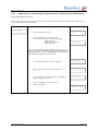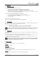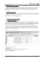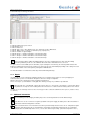
1
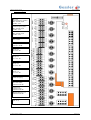
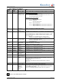
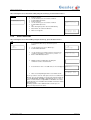
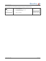
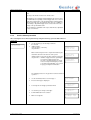
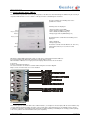
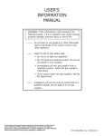
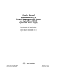
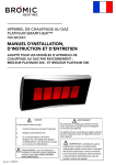
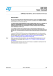
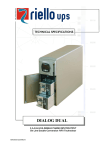
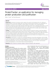
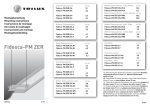
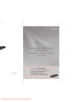
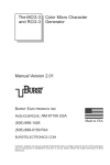
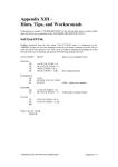
Manual
NANO 2
LPS-system according to EN50171
NANO 2 Low Power System
State: 07.03.2012
Table of Contents
1
2
3
4
Introduction ..................................................................................................................................... 2
Intended use ................................................................................................................................... 2
Description ...................................................................................................................................... 2
Technical Data ................................................................................................................................ 2
4.1
General ................................................................................................................................... 2
4.2
Connecting Consumers Power .............................................................................................. 2
4.3
Operating mode ..................................................................................................................... 3
4.3.1 Operating mode current monitoring ( absolute and relative current measurement )......... 3
4.3.2 Operating mode lamp monitoring ...................................................................................... 3
5
Connection plan .............................................................................................................................. 4
6 Panel and display .............................................................................................................................. 6
6.1
Key assignment ...................................................................................................................... 6
6.2
Meaning of LED Display......................................................................................................... 6
6.3
Menu structure ....................................................................................................................... 7
6.3.1 Service menu Language .................................................................................................... 7
6.3.2 Service menu Light Control ............................................................................................... 8
6.3.3 Service menu Device ID .................................................................................................... 9
6.3.4 Service menu USB............................................................................................................. 9
6.3.5 Service menu Buzzer ....................................................................................................... 10
6.3.6 Service menu Test Time .................................................................................................. 11
6.3.7 Service menu System Info ............................................................................................... 12
6.3.8 Service menu Clear Log .................................................................................................. 13
6.3.9 Service menu Clock ......................................................................................................... 13
6.4
Protocol book ....................................................................................................................... 14
6.4.1 Protocol book for operating mode lamp monitoring ......................................................... 15
6.4.2 Protocol book for operating mode current monitoring ..................................................... 16
6.4.3 Manual entry of a defect lamp in the protocol book ( absolute current measurement ) .. 17
7
Commissioning ............................................................................................................................. 19
7.1
Switching on the mains supply ............................................................................................. 19
7.2
Calibration and Registration ................................................................................................. 19
8
Testrelease ................................................................................................................................... 20
8.1
Manual test release .............................................................................................................. 20
8.2
Function test ......................................................................................................................... 20
8.3
Duration test ......................................................................................................................... 20
8.4
Menu Settings ...................................................................................................................... 20
9
Maintained / non maintained mode............................................................................................... 21
9.1
Mode current monitoring: ..................................................................................................... 21
9.2
Mode lamp monitoring: ......................................................................................................... 21
9.3
Manual Switch back to non maintained light ( meeting facilities )....................................... 21
9.4
Lighting Control ( energy saving ) ........................................................................................ 22
10 Emergency light blocking .............................................................................................................. 22
11 Operation oft he emergency lighting ............................................................................................. 22
11.1
Test / USB Stick / CSV file ................................................................................................... 22
11.2
Repair ................................................................................................................................... 23
12 Additional information ................................................................................................................... 23
13 Fault indication panel „FMT-01“ .................................................................................................... 25
14 Network-Interface.......................................................................................................................... 25
15 Housing assembly and drilling plan .............................................................................................. 26
Technical changes excepted
Page 1 of 27
NANO 2 Low Power System
1
State: 07.03.2012
Introduction
The guide is aimed exclusively at qualified electricians or persons instructed by electrical specialists. It contains summary
information about installation, operation, testing and maintenance. To avoid problems or damage during installation and
operation of the device, the instructions must be observed. The following symbols refer to particular risks or facilitate the work to
be performed:
Important ! The symbol indicates special hazards, the damage may result to persons or property. By following the
instructions you can also avoid an increase of effort in the implementation of the work.
Attention ! This sign is an advice to execute a necessary activity easily.
2
Intended use
The luminaires have to be suitable for operation on AC and DC.
The luminaries have to be operated within the specified voltage ranges.
The connected load of the lamps in emergency mode is not allowed to exceed 200W (225V DC)
In the assembly / installation and operation of the device these instructions and the applicable regulations have to be strictly
observed. Upcoming damages due to non-observing are excluded from liability, warranty and guarantee.
3
Description
Security lighting device for decentralized arrangement, each within a fire compartment, to supply a maximum of 2 x 16 rescue
signs and / or security lighting such as with cold cathode fluorescent lamps or LED with power in case of faulty main. The
emergency power is supplied through low-maintenance, sealed lead acid batteries.
The running of the Pb-battery at an ambient temperature <10 ° C and> 25 ° C leads to a reduction in service life,
combined with capacity losses and possibly a premature failure.
The Nano 2 needs to be maintained regularly by trained experts to ensure the operational function according to the
valid regulations.
4
4.1
Technical Data
General
Power supply:
System fuse:
Output voltage:
Continuous power (emergency mode):
Emergency duration:
Permissible ambient temperature :
Maximum cable length:
Minimum power per group:
4.2
1~/ N 230 V; max. 0,625 A; 50 Hz
16A (characteristic B
230 V ~ ( AC-Operation ) / 225 V = ( DC-Operation ) +/-7%
max. 200 VA
1 h, 3 h or 8 h
+ 5 to + 40 °C ( electronic ) / 0 to + 20 °C ( accumulator )
500m from circut
3 VA ( lamp )
Connection Loads Rating
The power consumption of some operating units in DC operation at the time of switching is bigger than the limit of the
overload or short-circuit disconnection of the device. An operation of such luminiares is prohibited. To determine the
exact running time the technical data of used gear have to be observed as well.
The connected load should be divided symmetrically between the two main groups ( group 1 and group 2 ).
If this is not, the maximum power rating of 120W per lamp group cannot be exceeded.
The total output of 200W has to be maintained in any case.
maximum connected load 200VA
Emergency Duration
Nominal capacity
Nominal capacity
10h Discharge duration
20h Discharge duration
1h
40 Ah
50 Ah
3h
100 Ah
120 Ah
maximum connected load 85VA
Emergency Duration
8h
Nominal capacity
Nominal capacity
10h Discharge duration
20h Discharge duration
100 Ah
120 Ah
The maximum battery size is ( High x Wide x Deep ) 250mm x 370mm x 180mm.
Technical changes excepted
Page 2 of 27
NANO 2 Low Power System
4.3
State: 07.03.2012
Operating modes
The Nano 2 can be used for the following modes:
4.3.1
Operating mode current monitoring ( absolute and relative current measurement )
Operating mode current monitoring ( absolute and relative current measurement )
Current monitoring:
Two groups of lamps / each group 2 circuits.
Each lamp group optionally configurable in maintained or non maintained mode.
Storage of the load current measured at the start of each lamp group.
Protocol book with up to 730 kinds of protocols. Through the USB interface it is possible the entire protocol book
to save to a USB stick.
Manual start of the function test by pressing a button.
Choice between daily, weekly or monthly function test and typing fixed test dates.
Visual indication of the need for an annual duration test. Programming of the triggering of the visual display is possible.
The duration test must be started manually.
During building rest periods the steady light of the lamps can turned off to save energy.
During operating time you can switch between English and German per menu.
Summer ( if enabled ) for error and system messages.
Setting of relative or absolute power measurement ( see also 6.3.7 Service menu “System Info” ):
Absolute current measurement: Error detection in a deviation of 3 watts per luminaire group. Suitable for systems with
a high number of consumers ( eg, 40 lights, each with 3W lamps ). At the absolute current measurement it is to ensure that
the status of the connected lamps before the commencement of trial operation corresponds to the state of the plant before
the balance ( maintained light or non maintained light ). After initial manual balance an alignment will be
repeated 24 hours later automatically by the system to realize the definite operating mode ( maintained light or non
maintained light ) of the luminaires.
Relative current measurement: Error detection in a current deviation of -20% / +40% for each group of lamps. Please
prefer the relative current measurement in systems with varying operating conditions ( eg. use of the switchable continuous
light, use of lighting control ), and end-users with higher loads. Ex works the system is set to the relative
current measurement.
4.3.2
Operating mode lamp monitoring
Operating mode lamp monitoring
lamp monitoring:
Two groups of lamps / 4 outputs with a total of 32 lights ( max. 16 per group ).
Remote controll of any lamp with Nano 2 compliant addressable monitoring modules.
Maintained and „non maintained“ lamps at the same circuit ( mixed mode ) - possible with compliant addressable switch
and monitoring modules.
Protocol book including the storage of faulty lamps with up to 730 possible records. Through the USB interface it is
possible to store the entire protocol book onto an USB stick.
Manual start of the function test by pressing a button.
Choice between daily, weekly or monthly function test and typing fixed test dates.
Visual indication of the need for an annual duration test. Programming of the triggering of the visual display is possible.
The duration test must be started manually.
During building rest periods the steady light of the lamps can turned off to save energy.
During operating time you can switch between English and German per menu.
Summer ( if enabled ) for error and system messages.
Technical changes excepted
Page 3 of 27
NANO 2 Low Power System
5
State: 07.03.2012
Connection plan
Message
main/emergency operation
Max. 250VAC / 2,5A
30VDC / 2,5A
Message
inhibit emergency active
Max. 250VAC / 2,5A
30VDC / 2,5A
General alarm contact
Max. 250VAC / 2,5A
30VDC / 2,5A
Output 12V DC
max. 100mA
Voltage Monitor
Attention 12V DC
Output
Group 2 B
b2- / B2+ / PE
Output
Group 2 A
a2- / A2+ / PE
Output
Group 1 B
b1- / B1+ / PE
Output
Group 1 A
a1- / A1+ / PE
Inhibit emergency
Manual control for BS
Fire alarm switch
!Attention 230V AC!
Critical circle
voltage monitor
!Attention 230V AC!
Maintained Group 1 / 2
!Attention 230V AC!
Mains connection
(PE / N / L)
Technical changes excepted
Page 4 of 27
NANO 2 Low Power System
6
State: 07.03.2012
Description of the terminals
Terminal
number
1/2/3
Associate
d Fuse
F1/F2
4/5/6
F3/F4
description
Note
230V AC - Mains
and charging
Switchable
maintained mode
for Group 1 and 2
In case of power failure or damaged fuse the Nano 2 switches to emergency
operation
Operating mode Lamp monitoring
Link from terminal 6 to 4 and 6 to 5
The decision maintained or non maintained mode must be set on
the monitoring module in each lamp
Operating mode Current monitoring
Group 1 maintained
Link from terminal 6 to 4
Group 2 maintained
Link from terminal 6 to 5
Group 1 switched maintained
Lamps on with closed contact between terminal 6 to 4
Group 2 switched maintained
Lamps on with closed contact between terminal 6 to 5
11/12
--------
13/14
-------
230V AC are
switched via
contact !
Fire alarm switch
15/16
--------
Inhibit emergency
(standard setting)
15/16
- Option -
---------
a1-/A1+/PE
F21/F21
a2-/A2+/PE
F23/F24
b1-/B1+/PE
F25/F26
b1-/B1+/PE
F27/F28
31/32/33
-----------
34/35
------------
36/37/38
-----------
Inhibit emergency
( Specify when
ordering )
Lampgroup 1
Circut 1a
Lampgroup 1
Circut 1b
Lampgroup 2
Circut 2a
Lampgroup 2
Circut 2b
Signal contact
main operation /
emergency
Signal contact
Inhibit emergency
General alarm
contact
39/40
41/42
--------
12V DC
Remote control
External electric
distribution
12V DC are
switched via
contact !
Attention: Terminals are leading mains voltage !
Don´t remove the jumper!
Depending on the operation mode - see "Capture 9” - the terminals have to
be opened, linked or connected to a switch.
a) Non maintained groups or lamps manually off after emergency = no link
b) Non maintained groups or lamps automatic off after emergency = link
c) Fire alarm switch
– Open to set non maintained groups or lamps in work
- Closed to reset groups or lamps in non maintained mode
Passive mode :
Linking the terminals F/f to activate
Note: ensure that multiple devices in parallel are connected on the
same Polarity of F / f
Active mode:
Activation by applying a control voltage
Allowable Control Voltage 6 to 12V DC
You absolutely have to pay attention to correct polarity of consumers(+/-L/N)
particularly in case of using monitoring modules
You absolutely have to pay attention to correct polarity of consumers(+/-L/N)
particularly in case of using monitoring modules
You absolutely have to pay attention to correct polarity of consumers(+/-L/N)
particularly in case of using monitoring modules
You absolutely have to pay attention to correct polarity of consumers(+/-L/N)
particularly in case of using monitoring modules
In main mode contact 31/32 is closed
In emergency mode contact 32/33 is closed
Contact closed when emergency light blocking is activated
In the following disturbance contact 37/38 is closed
- Not enough battery capacity detected in the last duration / function test
- Lamp failure during the last function test
- Charging error
- Emergency mode although emergency light blocking is activated
- Device off
Power supply for peripheral systems ( panel „FMT-01“ )
Control of a 2nd electric network by using voltage alarm.
In case of breakdown of this network the contact on the terminal 42 ( + NW )
and 41 ( NWC ) is open and the supply of lampgroups takes place by the
rest of remaining AC-network.
If there is no monitoring terminals 42 and 41 have to be jumpered.
Caution : The terminals may have voltage!
Technical changes excepted
Page 5 of 27
NANO 2 Low Power System
6
State: 07.03.2012
Panel and display
Start function test
Confirmation
Protocol book
Menu
Clock
Boost charge
Trickle charge
Emergency operation
Charging fault
Luminaire group 1
1
2
3
4
5
6
Test ( Function / Duration )
Luminaire group 2
Deep discharge protection
Capacity error
Inhibit emergency active
Provision BS lights
6.1 Key assignment
Button
Protocol book
Menu
Start function test
Confirmation
Function
Description of the display-protocol-book
Call the main menu for selection and query
Trigger a manual test,
Triggering a system-required duration test
Acknowledge the message “deep discharge” when activated / acoustic messages
Provision BS lights ( non maintained light )
Clock
Enabling the date and time display
▲ ▼
Up / Down – scroll in the selected menu
With each press the backlight will be on for about 10 minutes.
6.2 Meaning of LED Display
LED
LED (1) - Status Display
LED (2) – Test display
LED (3) - Group 1
indicator lamp
LED (4) - Group 2
indicator lamp
LED (5) – Indicator
Inhibit Emergency mode
Provision BS lights
LED (6) – Indicator
Shutdown by discharging
Technical changes excepted
Display
FLASHING GREEN = Main operation - boost charge the battery
DURATION GREEN = Main operation - maintenance charge of the battery
ORANGE FLASHING = Battery operation ( emergency operation )
Red = Disturbed or defective charge
FLASHING ORANGE ( 0.5 sec. Clock ) = Function test runs
FLASHING ORANGE ( 2 sec. Clock ) = Duration test runs
DURATION ORANGE = Request start duration test ( activated by pressing a key )
ORANGE FLASH = Display transition between states ( at test start and end )
See also chapter “manual test release”
PERMANENT RED = In the last test an error was found in luminaire group 1
or = The currently displayed entry in the log book contains an error in a luminaire group 1
DURATION GREEN = Light Group 1 in the last test with no errors
PERMANENT RED = In the last test an error was found in luminaire group 1
or = The currently displayed entry in the log book contains an error in a luminaire group 1
DURATION GREEN = Light Group 1 in the last test with no errors
ORANGE FLASHING = emergency light blocking is activated
PERMANENT ORANGE = Manual downshift of Non maintained groups after main fault is required
FLASHING RED = In the last test a battery capacity fault was found
or = The currently displayed entry in the log book contains a battery capacity fault
PERMANENT RED = Deep discharge was activated in the last emergency operation
The Indicator “deep discharge” must be confirmed by pressing the button “test release”.
Page 6 of 27
NANO 2 Low Power System
State: 07.03.2012
Only after the confirmation, a new test can be started.
The LED indicator flashes very quickly until the acknowledgment has been confirmed by the system
6.3
Menu structure
Please refer to the associated drawing „Menu Structure Nano 2 ".
Main screen
Display
• Measured voltage of the battery
• Charging current in main mode
• Discharge current in emergency mode
U battery: 13,8V
I charge : 2,4A
Because of the measurement method, it takes a few seconds to show on the display updated data.
The Menu button is used as a starting point for starting the service menu =>
Press the Menu button =>
Selection of submenus by pressing the arrow keys =>
Service
•
•
•
•
•
•
•
•
•
-SERVICE>Cancel<
6.3.1
Language ( German or English )
Light Control ( Energy saving while building rest periods )
Device ID
USB ( Write protocol )
Buzzer ( enable / disable )
Test Time ( Functional testing / duration test )
System Info ( System information )
Clear log ( Clear memory protocol )
Clock ( Set time )
-SERVICE>Language<
.
.
.
.
.
-SERVICE>Clock<
Service menu language
After selecting the service menu language by using the arrow keys, press the button menu =>
Language
>English<
Technical changes excepted
Use the arrow keys to select English or German
Use button to confirm menu choice
Main screen appears
U battery: 13,8V
I charge : 2,4A
Page 7 of 27
NANO 2 Low Power System
6.3.2
State: 07.03.2012
Service menu Light Control
After selecting the service menu light control by using the arrow keys, press the button menu =>
Light control
-Light control>Cancel<
Use the arrow keys to select the following sub-menus:
>Weekly<
>Vacation<
>Manual<
With button menu choice of sub-menus confirm
eg. Weekly space 1
Use the arrow keys to select memory 1-7
( 7 presets are available )
Selection of the character with the button Menu
( selected character will flash )
Selection of the value to be set using the arrow keys
( Letter A stands for activating the saving time )
When all characters are set, navigate ( no character may
blink more, otherwise button Menu press briefly ) with the
arrow keys on –Weekly- > Return<.
Press the button Menu to exit the submenu
Weekly.
-Light control>Weekly<
1 – MO 00:00
MO 00:00
1 A MO 15:00
MO 18:00
-Weekly-
uerung
>Return<
-Light control>Cancel<
Now make other settings in the submenu of lighting control
( selection by arrow keys ) or leave service menu “Light
Control” by pressing the button Menu.
Main screen appears
U battery: 13,8V
I charge : 2,4A
Note: The same procedure applies to the setting of the vacation
( also 7 presets with additional input date ). When the times in the
sub-menu Weekly and sub-menu Vacation are activated, it must be
ensured that the sub-menu Manual “Light Control” is set to automatic =>
Select sub-menu Manual by using the arrow keys in the
service menu “light control”
-Light Control>Manual<
Confirm with button Menu selection
Use the arrow keys Automatic or Manual off
select.
Confirm with button Menu selection
Light Control
Manual Off
-Light Control>Cancel<
Leave „Light Control“ service menu by pressing the menubutton
U battery: 13,8V
I charge : 2,4A
Main screen appears
Note: continious lighting can be manually turned off for an indefinite
period of time. Manual control has priority over a programmed
vacation period. Vacation period in turn has priority over a
programmed weekly period.
Attention: When you activate the light control in the main display
every 3 seconds the signature "Light Control Active" will be
shown for 1 second.
Technical changes excepted
Light Control
Active
Page 8 of 27
NANO 2 Low Power System
6.3.3
State: 07.03.2012
Service menu Device ID
After selecting the service menu Device ID by using the arrow keys, press the button menu =>
Device ID
- Device ID –
----------------
6.3.4
Position 1 flashes
Use the arrow keys to select letters / numbers
Confirm with button Menu
Position 2 flashes
Use the arrow keys to select letters / numbers
Confirm with button menu
etc.
After entering the position 16 and confirmation by
button Menu, the sub-menu will leave
- Device ID LPS-----00000013
Main screen appears
U battery: 13,8V
I charge : 2,4A
Service menu USB
After selecting the service menu USB by using the arrow keys, press the button menu =>
USB
Put standard USB memory stick into the port of
device !
- USB –
>Cancel<
Use the arrow keys to select > Write Log <
Confirm with button Menu
Use the arrow keys you want to transfer select protocols
( number in parentheses = last protocol ) => from ... to
Each confirm with button menu
Writing operation is initiated by specifying the
number of records to be transferred
If a transmission error or no USB stick, an error is displayed
After successfully writing the main screen will be shown
- USB >Write Log<
Log from...to
001...100 (100)
USB...100
USB error
U battery: 13,8V
I charge : 2,4A
Note: It is possible to save the entire protocol book on a USB stick via
USB port. The corresponding file is saved in CSV text format and can
be used in MS-EXCEL / OpenOffice. Regarding the process-sing of
data it is recommended to use OpenOffice or LibreOffice. For a later
system-allocation a free definable device ID with 16 characters will be
written into the file.
The writing operation on the USB flash drive can take up to 15
minutes for 730 protocol book entries.
Technical changes excepted
Page 9 of 27
NANO 2 Low Power System
6.3.5
State: 07.03.2012
Service menu Buzzer
After selecting the service menu Buzzer by using the arrow keys, press the button menu =>
Buzzer
- Summer –
Off
Current setting flashes
Use the arrow keys select On or Off
Confirm with button Menu
Main screen appears
Technical changes excepted
- Buzzer –
On
U battery: 13,8V
I charge : 2,4A
Page 10 of 27
NANO 2 Low Power System
6.3.6
State: 07.03.2012
Service menu Test Time
After selecting the service menu Test Time by using the arrow keys, press the button menu =>
Test Time
Use the arrow keys to select the following sub-menus:
>Program FT< ( function test )
>Program BT< ( duration test )
- Test Time –
- Test Time –
>Program FT<
>Cancel<
Confirm with button menu selection sub-menu >Program
FT< ( function test )
Selection of the character with the button Menü ( selected
character will flash )
Selection of the value to be set using the arrow keys
Choose between daily, weekly or a monthly function test
( 005 as the last character block = 5 minutes )
FT Daily
23:00 005
FT Weekly
MO 23:00 005
FT Monthly
MO 12 23:00 005
When all characters are set and passed through it
automatically changes to the submenu
- Test Time >Cancel<
Make other settings in the submenus of test times (elected
by the arrow keys) or leave service test times by pressing
the menu-button
Main screen appears
U battery: 13,8V
I charge : 2,4A
Note: There is a choice between daily, weekly or monthly function
test. Depending on the selection different settings can be programmed.
Daily function test:
Time / duration => Testing releases once per day for the programmed
time out.
Weekly function test:
Day / time / duration => Testing releases automatically at the
specified day of the programmed time.
Monthly functional test:
The test automatically triggers at the specified weekday after day of
the month at the programmed time of day. Alternatively, also an accurate test date can be selected . Then the test automatically triggers
the programmed date. The duration of the test can be programmed
from 5 up to 15 minutes. The resolution setting is 1 minute.
The same procedure applies to the setting of the duration test =>
- Test Time –
>Program BT<
Confirm with button menu selection sub-menu >Program
BT< ( duration test )
Selection of the character with the button Menü ( selected
character will flash )
Selection of the value to be set using the arrow keys
When all characters are set and passed through it
automatically changes to the submenu
MO 31.12
16:00 180
- Test Time >Cancel<
Make other settings in the submenus of test times (elected
by the arrow keys) or leave service test times by pressing
the menu-button
Main screen appears
U battery: 13,8V
I charge : 2,4A
Technical changes excepted
Page 11 of 27
NANO 2 Low Power System
State: 07.03.2012
Note: For a duration test the following information can be programmed:
Day / day of the month / month / hour / minute / time
The duration test is not triggered automatically by the system. There
is an LED indicator requesting a manual trigger start of use. The test
requirement is dependent on the programmed time and input will be
carried out the day of the week after the date entered. In addition to
the weekday, a day-definite trigger can be selected. Then the call is
exactly on the specified date / time.
The test duration is adjustable from 15 up to 480 minutes, adjustable
in steps of 15 minutes.
6.3.7
Service menu System Info
After selecting the service menu System Info by using the arrow keys, press the button menu =>
System Info
>Mains Return<
31.08.11 08:40
Use the arrow keys, the following sub-menus
be selected:
>Mains Return<
>Current Type< ( sub-menu )
>System Info<
Mains return and system info is only an information to give
statements about the current state of the system:
>Mains Return<: Last power up after emergency operation
>System Info<: Number of logged onto the system lights.
In a current-controlled system, the
message "currentmonitoring" are shown.
In case of single monitoring it is possible
to show all registered lights ( press arrow
keys) by pressing the menu-button.
>Mains Return<
31.08.11 08:40
>System Info<
Reg.Lumin. 32
>System Info<
Currentmonitor
The following selection is only possible in current-controlled
systems=>
Use the arrow button menu > Current Type <
Present current type is displayed
To change the current type push button menu
Use arrow keys to change current type
Confirm with button menu selection
Main screen appears
Technical changes excepted
>Current Type<
act: relativ
- Current Type > relativ <
- Current Type > absolut <
U battery: 13,8V
I charge : 2,4A
Page 12 of 27
NANO 2 Low Power System
6.3.8
State: 07.03.2012
Service menu Clear Log
After selecting the service menu Clear Log by using the arrow keys, press the button menu =>
Clear Log
Clear ?
>Cancel<
Change with the arrow key to >Clear Log<
Clear ?
>Clear Log<
Confirm with button menu selection
Entire protocol is deleted
--730
Note: The progress is in evidence of the current numbers. If the
number reaches 0, the deletion is complete. Due to the amount of
memory this function needs several minutes.
After the deletion the main screens appears
6.3.9
U battery: 13,8V
I charge : 2,4A
Service menu Clock
After selecting the service menu Clock by using the arrow keys, press the button menu =>
Clock / date
Setting the date and time for the protocol book and test trips
MO 05.09.11
08:55:03
Weekday flashes. Selection of those to be
value or weekday with the arrow keys
Confirm selection by pressing the button menu. After
confirmation flashes the keypad next to be set. selection the
adjusted number pad with the arrow keys, etc.
TU 06.09.11
08:57:00
Note: The seconds can not be set. You can only zeroise them by
using the arrow key. When leaving, the currently shown time is saved.
When all characters are set and passed through it
automatically changes to the main screen
U battery: 13,8V
I charge : 2,4A
Note: The change from summer to winter time or from winter to summer time will be carried out automatically.
Technical changes excepted
Page 13 of 27
NANO 2 Low Power System
State: 07.03.2012
6.4 Protocol book
The button protocol book serves as a starting point for the retrieval of stored test protocols
=> press the button protocol book =>
Protocol book
Protocol of the last tests will be shown
P004 FT OK
04.09.11 23:05
The following information is shown:
Protocol number of the last test performed
Type of test: - FT ( Function Test )
- BT ( duration test )
- MT ( manual test )
- DF ( shifted test )
Results of the tests: - OK ( test ok )
- Error ( test error )
Test Date
Test time ( time trial end )
If no test was performed and recorded then "No Log" will be
shown on the display.
P004 FT OK
04.09.11 23:05
No Log
Note: Use the arrow keys to thumb through the protocols. The
indicator LED’s of the lighting group 1, lighting group 2 as well as the
LED of the capacity error will be set in accordance with the
selected protocol.
In case of not pressing any buttons in a menu for more than 60 seconds, the system automatically switches back to the
main screen.
Technical changes excepted
Page 14 of 27
NANO 2 Low Power System
6.4.1
State: 07.03.2012
Protocol book for operating mode lamp monitoring
Press the button protocol book =>
Lamp monitoring
P004 FT OK
04.09.11 23:05
Without error in the test
Press the button protocol book once again:
Display: Protocol number ( here P004 )
Batt. ok = battery capacity sufficient
Lamps OK = no lights error is detected
P004 FT OK
04.09.11 23:05
P004 Batt. ok
Lamps OK
To exit the display press the menu-button
Main screen appears
U battery: 13,8V
I charge : 2,4A
With error in the test
P004 FT Error
04.09.11 23:05
Press the button protocol book once again:
Display: Protocol number ( here P004 )
Batt. ok = Battery capacity sufficient ( ex. )
Batt. Kap = Battery capacity is not sufficient
Group number = Group 1 ( ex. )
Lighting lamp number = Lamp 05 ( ex. )
Lighting condition = Lp err. ( defective lamp )
missing ( no feedback of the
light )
Use the arrow keys to scroll through the menu to show any
defective or missing lamp.
P004 Batt. ok
G1 L05 Lp err.
P004 Batt. ok
G2 L03 miss.
To exit the display press the menu-button
Main screen appears
Technical changes excepted
U battery: 13,8V
I charge : 2,4A
Page 15 of 27
NANO 2 Low Power System
6.4.2
State: 07.03.2012
Protocol book for operating mode current monitoring
Press the button protocol book =>
P004 FT OK
04.09.11 23:05
Current monitoring
Without error in the test
Press the button protocol book once again:
Display: Protocol number ( here P004 )
Batt. ok = battery capacity sufficient
Lamps OK = no lights error is detected
To exit the display press the menu-button
Main screen appears
With errors in the test
Press the button protocol book once again:
Display: Protocol number ( here P004 )
Batt. ok = Battery capacity sufficient ( ex. )
Batt. Kap = Battery capacity is not sufficient
Err.G1 = Error in Group 1 found ( ex. )
Err.G2 = Error in Group 1 found
Err.G1 Err.G2 = Error in Group 1 and Group 2
found
P004 FT OK
04.09.11 23:05
P004 Batt. ok
Lamps OK
U battery: 13,8V
I charge : 2,4A
P004 FT Error
04.09.11 23:05
P004 Batt. ok
Err.G1
To exit the display press the menu-button
Main screen appears
Technical changes excepted
U battery: 13,8V
I charge : 2,4A
Page 16 of 27
NANO 2 Low Power System
6.4.3
State: 07.03.2012
Manual entry of a defect lamp in the protocol book ( absolute current measurement )
Press the button protocol book =>
Note: If connected to a current monitoring system with absolute current measurement of several lamps, broken lamps can be
entered and recorded on the protocol book.
P004 FT Error
04.09.11 23:05
Press the button protocol book
Press the button protocol book once again
Ad man. Error List: Protocol number ( here P004 )
Group ( here G1 )
Lamp number ( here L01 )
Status ( here OK )
P004 Batt. ok
Err.G1
Man.Err.List
P004 G1 L01 OK
Note: In each group 20 lamps can be marked as defective. Use the
arrow keys to reach the relevant lamp-number. After reaching lamp L20
it automatically switches on lamps skipped G2 group (Group 20 L01).
Mark Sample light 5 / Group 1 to be defective
Set arrow button until group 1 lamp L05 appears
Man.Err.List
P004 G1 L05 OK
Press the menu-button. The status changes to L05
err.
Man.Err.List
P004 G1 L05 err.
Press the button protocol test. Setting is saved. Display
jumps to the protocol overview
P004 FT Error
04.09.11 23:05
To exit the display press the menu-button
Main screen appears
Technical changes excepted
U battery: 13,8V
I charge : 2,4A
Page 17 of 27
Technical changes excepted
Menu Protoc ol
Book
Menu Servic e
Butt
on
Taster
(Selection Protocol)
Taster
Butt
on
Ackno wled gment buzzer
when set
Or
Ackno wled geme nt d eep
discha rge pro tection
when set
Or
Duration test if
a utoma tic re quest
Or
Func tion te st
Dura tion de pending on the
set test time
Start
Button
Taster
(Submenu Selec tion)
Button
Taster
Menu
Button Protoc ol Single Protocol
Book
Button m enu
Start
Menu Struc ture Nano 2
Button Menu
Button Protoc ol Book
Button
Start func tion
test
Menu Start
Start
Button Menu
Button Menu
Lig ht Co ntrol
De vic e ID
Button Menu
Syste m Info
Clo ck
C lea r
lo g
Button Menu
Test Tim e
Button Menu
Button
Taster
(Selection Function)
Taster
Button
Button Menu
Buzzer
Button Menu
Button Menu
La ngua ge
USB
Button Menu
Button Menu
Button Protoc ol Book
Ca nce l
Button
Taster
(Selection Lamps)
Taster
Butt
on
Start
Start
Button Menu
Button
Taster
Taster
Button
Butt
on
Taster
Butt
Taster
on
Butt
on
Taster
Taster
Butt
on
Put selec tion
to the en d
Ca nce l
C lea r
Start
Button Menu
Disp la y of the
de letion
Button Menu
Start
Start
Se le ctio n
relative / ab solu te
Ap p ea l p end ing
lights
Button Menu
Put selec tion
to the en d
Taster
Butt
on
Taster
Button
(Setting)
Butt
Taster
on
Taster
Butt
on
(Setting)
Button
Taster
Button
Taster
(After each c haracter c hange
press the button menu !)
Start
Start
Button
Taster
(Setting)
Butt
Taster
on
Button
Taster
(Setting)
Taster
Butt
on
Button Menu
Butt
Taster
on
(After each c haract er c hange
press the button menu !)
Butt
Taster
on
Taster
Butt
on
(After each c haract er c hange
press the button menu !)
Butt
on
Taster
Ca nce l
Button Menu
Current
Type
Exit
Butt
on
Taster
(Tim e Block set)
Button
Taster
Put selec tion
to the en d
Button Menu
Tim e Blo ck
Butt
Taster
on
(Setting)
Butt
on
Taster
Butt
Taster
on
(After each c haracter c hange
press the button menu !)
Butt
Taster
on
Start
Button Menu
Taster
Button
Taster
Butt
on
(Einstellung)
Button Menu
Start
Start
Butt
on
Taster
Butt
Taster
on
(Setting)
Start
Start
Button Menu
Button Menu
Se le ctio n:
Auto m atic
Man uel Off
Button Menu
Button Menu
Registered
lamps
Mains return
Ca nce l
Se le ctio n:
FT / BT
Se le ctio n:
On/ Off
Write p ro toc ol
Put selec tion
to the en d
Ca nce l
Button Menu
Manua l
Weekly
Va ca tio n
Se le ctio n:
Germ a n/English
NANO 2 Low Power System
State: 07.03.2012
Page 18 of 27
NANO 2 Low Power System
7
State: 07.03.2012
Commissioning
For proper operation with the implementation of automatic testing and reporting faulty lights, gradually commissioning
as per the following instructions is mandatory.
Errors that arise due to deficient or incomplete implementation of commissioning are not subject to the warranty.
When commissioning is initiated, connected luminaries without integrated address module are detected and the mode " current
monitoring " will run. The load current is measured and stored. During a test the Nano 2 compares the actual measured load
current with the one stored current. Variations in a specified amount in the system lead to the indicator " error in luminaire
group * "
Luminaries equipped with an address module are detected automatically during the commissioning. The Nano 2 activates
independently the operating mode "lamp monitoring" and applies the detected address.
The process of commissioning is the same for all operating modes
When commissioning an automatic detection of the modes occurs.
The common operation of lamps with and without address modules is not allowed. The NANO 2 switches in the
recognition of address modules during the login automatically to the lamp monitoring mode. Current deviations due to
the failure of lights are not evaluated or shown. A duplicate address in a group of lamps is not allowed to be existent.
Before commissioning starts the correct connection of all cables and consumers must be examined according to the
wiring diagram. Damage caused by connection errors are not subject to the warranty.
7.1
Switching on the mains supply
•
•
•
•
•
7.2
The indicator LED (1) shows permanently or flashing green.
The lamps in a non maintained light group are in standby operation. (No link 4-6 / 5-6).
The lamps in a maintained light group are in continuous operation. (Link 4-6 / 5-6 in).
For setting maintained or non maintained mode please read the chapter 9.
Luminaries with address modules are in standby or continuous operation similar to the setting of the mode switch and
depending on the prior operating.
Calibration and Registration
•
•
•
•
Check the indicated charging voltage - this should be significantly higher than 13V. The charge current should be less
than 0.5 A to ensure that the battery has sufficient capacity for commissioning.
Press the button LM test ( see wiring diagram or chapter 15 housing assembly - detailed View A ).
The device switches from main to emergency operation. The LED “LM-test” will flash red for a short time. Then the
LED changes to permanent red. The application can take up to 5 minutes depending on operating mode.
When current measurement or registration of lamps with address module was successful, the LED “LM-Test” will
switch off.
•
Check the results on the menu “System Info” ( chapter 6.3.7 ). The number of registered lights must match the
number of mounted lights. For lamps without address modules it automatically switches to the mode "current
monitoring". In the operating mode "lamp monitoring" is the possibility to switch between relative and absolute current
monitoring. When using the relative current monitoring, the deviation is calculated as a percentage (-20% / +40%).
When using absolute current monitoring a deviation from 3W ( Bulb ) from the measured current value ( Calibration )
is recognized as an error. At the absolute current measurement it is to ensure that the status of the connected lamps
before the commencement of trial operation corresponds to the state of the plant before the balance ( maintained light
or non maintained light ). After initial manual balance an alignment will be repeated 24 hours later automatically by the
system to realize the definite operating mode ( maintained light or non maintained light ) of the luminaries.
On commissioning you have to pay attention if relative or absolute current monitor is set for the operation mode
"current monitoring" ( see also 6.3.7 System Info ).
The correct display of the current type in the mode "current monitoring" may take up to a minute to change.
•
•
Enter in the "Time / Date" ( see. 6.3.9 service menu clock ) the current date and time.
Program in the menu "test time" ( see 6.3.6 ), the test time of annual duration and functional tests.
•
If the above steps have been carried out successfully, you should check the function of Nano 2 by triggering a manual
test.
If this testing is successful, the device is ready now.
•
The power of the connected lamps can only be determined correctly when all lamps are connected.
In case of adding, removing or replacing lamps to the system the commissioning has to be repeated.
Technical changes excepted
Page 19 of 27
NANO 2 Low Power System
8
State: 07.03.2012
Testrelease
8.1
Manual test release
A first manual test has to be carried out after commissioning.
•
•
•
•
After pressing the manual test button, the “Test” LED flashes very quickly (FLASH).
The Nano 2 requires a short period of time to verify whether a test can be started.
If the test can be started, the display of the LED "TEST" changes from fast to slow orange flashing.
A manual test is based on the set time of the functional tests. If the functional test is set to 5 minutes, so the manual
test also lasts 5 minutes and then shuts off automatically.
Should it be necessary to stop the test prematurely, proceed as follows.
•
•
•
•
Press the manual test button again until the “Test” LED flashes very quickly.
The Nano 2 will interrupt the test and turns back to the status that existed before the test.
The LED "test" will flash orange once and turns off.
The test is terminated.
Manual tests can only be activated from the Start menu.
To get a correct result, the duration of the test should be at least 5 minutes.
8.2
Function test
Depending on weather the selected time interval is daily, weekly ( every 7 days ) or monthly an automatic function test will be
activated. The test duration can be freely selected between 5 and 15 minutes.
Shift of the function test in case of power failure:
Emergency operation for up to 4 hours before test initiation delays the test by 24 hours
A power failure during the function test moves the test for 24 hours after mains return
From the time of the original test activation the display of the displacement on the display is visible. The test time will
automatically reprogramm. After completion of the delayed test the original test time is programmed. The delayed tests
show in the test protocol type "DF". A daily test will be reprogrammed temporarily for the delay to a weekly test.
8.3
Duration test
If the set release date reached the duration time test, the system calls by a permanently lit LED (2) the manual activation of a
duration test.
The duration test must be performed by pressing the button ( Start function test ) to activate the test. The procedure is as for the
manual test trip. Depending on the connected battery and load fitting a test can run for 1 or 3 hours.
According to EN62034 section 6.3.3 a manual activation is to ensure that the test is conducted at a time with low risk. In the
protocol book the result of the duration test is recorded.
An automatic delay of the duration test because of a power failure is not provided. A duration test is activated manually
on the device. In the service menu "System Info" submenu must "mains return" has to be checked if and when a power
failure has occurred ( date and time of last connection to the main is shown ). In case of a power failure the manual
activation is only allowed to be activated after 24 hours at the earliest.
8.4 Menu Settings
With the menu ( see Menu Structure 6.3 ) you can do the following settings:
Language:
Selection: German or English
Light Control:
Selection:
Weekly Time: 7 presets
Holiday Time: 7 presets + entry date
Manually off for an indefinite period
The manual control has priority over a scheduled weekly time. The programmed weekly time takes precedence over a
scheduled holiday time.
Device ID:
For a clear assignment of a read test report ( eg for objects with multiple operating units ).
Technical changes excepted
Page 20 of 27
NANO 2 Low Power System
State: 07.03.2012
USB:
With the USB interface it is possible to save the entire protocol book on a USB stick.
Buzzer:
Selection: On or Off.
Sound ( Buzzer On ) with the following error messages:
Charge failure, emergency operation, mains monitoring.
Test Time:
Functional test: daily, weekly or monthly.
Programmable from 5 to 15 minutes (Resolution 1 minute)
Duration test: No automatic release! There is an LED display which requests a manual start by user. Programmable 15 -480
minutes ( resolution 15 minutes ).
System Info:
Mains return: About the last power up after emergency operation.
System Info - registered lights: Number of lamps logged into the system. In a current-controlled System, the message "current
monitoring" is shown.
Current Type: For current monitored systems ( no function for lamp monitoring ! ).
Relative: Error detection in case of deviation -20% / +40%.
Absolute: Error detection in case of deviation from 3W ( bulbs ).
Clear Log:
Delete the protocol report ( max. 730 protocol entries ).
Clock:
Setting the date and time for the protocol entries.
9
Maintained / non maintained mode
9.1 Mode current monitoring:
The lights can be switched with switch on the feeder clamp ( maintained light group 1 or maintained light group 2 ). When the
lights are off due to these terminals ( non maintained light ) they can be turned on by using the following functions:
•
Open the switch for fire alarm system.
When the switch fire alarm system is open, this has priority over other switching operations.
9.2 Mode lamp monitoring:
Precondition:
The terminals for maintained light group 1 or maintained light group 2 are jumpered in accordance with wiring
diagram.
The monitoring device of switchable lamp must be set to non maintained light.
Then the switching of the light is possible
•
Open the switch for fire alarm system.
When the switch fire alarm system is open, this has priority over other switching operations.
The maintained light will be turned on or off temporally delayed ( up to 1 minute ) because firstly there has to be made a data
transfer between the individual components of the system.
9.3 Manual switch back to non maintained light ( meeting facilities )
For meeting facilities, a manual downshift of the non maintained lights after a power failure of the loading phase and on the
response of the voltage monitors is required.
To the possibility of manual downshift, the fire alarm switch must be open. For an automatic downshift to the fire alarm switch is
closed.
The display of a manual downshift results from the LED "Provision BS lights". With the button "Confirmation" LED goes out and
the return circuit is controlled by up to 1 minute.
By installing a switch the fire alarm switch can switch non maintained lights on or off. After opening the fire alarm switch, the
LED "Provision BS lights" will be turned on. Now the light can be turned off by using the button "Confirmation" or by closing off
the fire alarm switch.
Technical changes excepted
Page 21 of 27
NANO 2 Low Power System
State: 07.03.2012
9.4 Lighting Control ( energy saving )
It is possible to turn off maintained light during rest periods (eg holidays, at night) to save energy (see also 6.3.2 service menu
light control). Maintained lighting can be adjusted manually for an indefinite Off period. For the setting of the weekly time 7
memory locations are available to set daily shut intervals. For setting the holiday season also 7 memory locations with an
additional date entry are available. Manual control has priority over a holiday period, which in turn takes precedence over a
scheduled weekly.
10 Emergency light blocking
The LED of the display are turned off in emergency mode and activated emergency light blocking. Only LED (5) - ( Emergency
lighting blocking / Provision BS lights ) is used to show the status of emergency light in case of power failure. The LED flashes
in the following cycle: 5 seconds OFF, 0.5 seconds ON.
A activated buzzer is turned off by emergency light blocking.
11
Operation of the emergency lighting
11.1 Test / USB Stick / CSV file
The device is part of a security lighting. According to the legal standards cyclic function tests and annual audits of operation of
emergency lighting have to be carried out. A protocol book is integrated. This can be read via the USB interface of the device (
CSV-File) and by using a spreadsheet program / text editor to view and edit ( recommended OpenOffice / LibreOffice). Due to
different methods for CSV import( columns separated by comma ) may be you have to consult the guidance of the spreadsheet
program. In the CSV-File you find all generated protocols and the current status of the lights are documented.
Due to the nature of the data access of USB flash drives, the writing operation will need some time (see also section 6.3.4
Service menu USB). The writing operation of the complete log memory with 730 protocol book entries may take up to 15
minutes. For a later system-allocation a free definable device ID with 16 characters will be written into the file. ( Assignment see section 6.3.3 Service menu Device ID ). In the case of a typographical error the message "USB Error" appears on the
display supported by an acoustic warning signal.
CSV-file with current monitoring performance:
Column A: Number of the protocol book
Column B: Date of test
Column C: End of test
Column D: Type of test => BT = Duration test / FT = Function test / MT = Manual test
Column E: Battery status => battery ok oder battery cap ( capacity error )
Column F: Group G1 => OK or error
Column H: Group G2 => OK or error
Technical changes excepted
Page 22 of 27
NANO 2 Low Power System
State: 07.03.2012
CSV-file with lamp monitoring performance:
Column A: Number of the protocol book
Column B: Date of test
Column C: End of test
Column D: Type of test => BT = Duration test / FT = Function test / MT = Manual test
Column E: Battery status => battery ok oder battery cap ( capacity error )
Column F: Number of registered lights
Column G: Group 1 => Number and address of the defective lamps
Column H: Group 1 => Number and address of the defective lamps
Column I: Group 2 => Number and address of the defective lamps
Column H: Group 2 => Number and address of the defective lamps
Due to the large number of different USB flash drives it can not be excluded that some sticks cancel the writing
operation prematurely. In this case, the USB flash drive from another manufacturer has to be used.
The protocol book uses the FIFO ( First In / First Out ). Upon reaching the end of memory, the oldest log will be deleted. The
built-in test equipment leads to the device function tests and service life tests automatically depending on the setting. The result
of the last test is visible on the control panel by looking at the LED indicators.
The manual activation of a functional test must be performed with charged battery.
11.2 Repair
If a failure appears on the control panel following a function test or a duration test, it must be to resolve promptly by an
authorized service person or an electrician. Exception to this is the change of a light tube.
After the repair on the control panel you have to initiate a functional test.
This is necessary to a) control that the security light unit is working correctly or b) confirm the reported fault.
When the 40A fuse of the DC-DC converter disconnects there is a short circuit or the battery is connected the wrong
way. When the 7.5 amp fuse of the loading device disconnects there is a device fault or the battery cables were shorted.
If in both cases, the exchange of the fuses does not help you need to contact an authorized service person ( location of fuses,
see item 15 ).
12
Additional information
To avoid damage from discharging, the battery may not be stored longer than three months without charge.
If the Nano 2 is set out of service for a long time (shutdown of the power supply) the battery has to disconnected after 1
at the latest month and charged after 3 months.
Make sure that the device is not mounted in areas where permanent temperature increases 25 °C. Temperatures higher
than 25 °C will reduce battery life. To avoid damages of the battery at temperatures higher than 25 °C a temperature
compensation circuit with temperature sensor ( see also item 15 Housing assembly - placement temperature sensor )
Technical changes excepted
Page 23 of 27
NANO 2 Low Power System
State: 07.03.2012
regulates the final charge voltage off during charging. The full capacity therefore can not be achieved or guaranteed at
temperatures over 25 °C. From 40 °C, the charge is switched off. For an efficient function of the temperature sensor the battery
must be pushed to the battery brackets or flush with this.
The device may be used for indoor applications only.
Technical changes excepted
Page 24 of 27
NANO 2 Low Power System
State: 07.03.2012
13 Fault indication panel „FMT-01“
The fault indication panel FMT1 shows the operating states of the Nano 2 to external authority. The tableau may be used only in
conjunction with the Nano 2. A cross-match or a wrong connection could damage the electronics.
The panel evaluates the switching states of the
potential-free contacts.
Following states are displayed:
System ok
Eme rge ncy ope ra tion
Disturba nce
- System operation ( green LED )
- Power supply from battery ( red LED )
- Device disturbed ( LED flashing red )
- Emergency prevented ( LED flashing red )
Eme rge ncy bloc ke d
The built-in buzzer sounds when the following error is
displayed :
- Device disturbed
- Emergency prevents
LED Test
Buzzer off
The buzzer is turned off via the "Buzzer off". The error (
optical and acoustical ) is reset, if the error was
corrected.
Whether the display LED and the buzzer work correctly can be controlled by the button "LED Test”
Pressing the button all the LED at the panel light on and the buzzer sounds.
When the button "LED test" is no longer pressed, the display switches back to the current status.
Connection:
Power is supplied from the Nano 2.
The other connections are made in accordance with below given connection diagram.
Only a correct connection leads to a correct evaluation.
14 Network-Interface
There is the option to connect the device via a network interface ( see chapter 5 Connection plan ) with the same network to any
computer. With the included software, the status of the system can be checked and protocols are available. There is also the
possibility of testing times and holiday periods and weekly set. When installing or retrofitting into an existing system the placing
of the user’s guide for the Network-Interface takes place separately.
Technical changes excepted
Page 25 of 27
NANO 2 Low Power System
State: 07.03.2012
15 Housing assembly and drilling plan
1.
2.
3.
4.
Lift up housing cover and remove to the front.
Set assembly area
Transfer the drilling plan in the specified dimensions on the mounting surface
Create the holes for fastening with a 10mm drill (pre-drill recommended)
5.
Fix the device with the supplied anchors to the assembly level.
Note! Because of the battery weight are both battery holding bracket to fasten with 2 screws fixed to the
mounting level
Lead cable through the rubber grommets into the housing and electrical connection acc. Connection diagram. The
cable catch rail is used for strain-relief of the introduced cable.
Put the battery on the mounting bracket and establish a connection. Therefore fix the battery cables (red = + / black =
-) with the provided screws to the corresponding pins
Attention! Reverse polarity of the battery will destroy the electronics! This error is not covered by warranty.
6.
Technical changes excepted
Page 26 of 27
NANO 2 Low Power System
State: 07.03.2012
Drillplan:
110
529
190
Technical changes excepted
Page 27 of 27