1
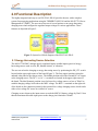
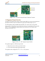
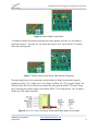
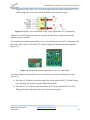
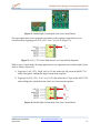
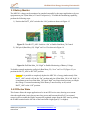
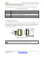
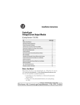
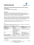
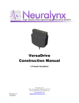
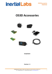
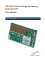
IPS-EVAL-EH-01 Energy Harvesting
Evaluation Kit
User Manual
UM003 (v 0.3) August 2011
IPS-EVAL-EH-01 Energy Harvesting Evaluation Kit
Revision History
Date
Version
Revision
07/07/11
08/04/11
0.1
0.2
0.3
Initial Draft
New hardware revision using Maxim MAX17710 PMIC
Added Appendix A: Schematic and Gerber Files
References
[1] THINERGY® MEC101 Datasheet
[2] Maxim MAX17710 Datasheet (19-5872; Rev 0, 6/11)
®
®
© 2011 Infinite Power Solutions, Inc. All rights reserved. Infinite Power Solutions , THINERGY and MEC, and the Infinite Power
Solutions, THINERGY and MEC logos are trademarks or registered trademarks of Infinite Power Solutions in various countries. All
other names are the property of their respective owners. Information in this document supersedes and replaces all information
previously supplied. All specifications are subject to change without notice.
UM003 (v0.3) August 2011
User Manual
www.InfinitePowerSolutions.com
2
IPS-EVAL-EH-01 Energy Harvesting Evaluation Kit
Table of Contents
Table of Contents ................................................................................ 3 1.0 Introduction .................................................................................... 4 2.0 Functional Description ................................................................ 5 2.1 Energy-Harvesting Source Selection ................................................................... 5 2.2 Regulated Output Selection ..................................................................................... 6 2.2.1 High-Current Mode ................................................................................................... 7 2.2.2 Low‐Current Mode ..................................................................................................... 9 2.3 Battery Monitor ........................................................................................................... 12 2.4 Off/Active Wake .......................................................................................................... 12 2.5 Battery Check LED .................................................................................................... 13 2.6 Boost Select ................................................................................................................ 13 3.0 Configuration and Connection ...................................................... 13 3.1 Slide Switches ............................................................................................................ 14 3.2 Momentary Push-button Switches ..................................................................... 15 3.3 Output Header (J1/J2) .............................................................................................. 15 3.4 Charging Terminals .................................................................................................. 17 3.5 Test Point Terminals ................................................................................................ 17 3.6 WAKE/GND Terminals ............................................................................................. 17 4.0 Physical Connector Information ............................................. 18 4.1 Output Header Mating Socket .............................................................................. 18 Appendix A: Schematic and Gerber Files ................................... 19 UM003 (v0.3) August 2011
User Manual
www.InfinitePowerSolutions.com
3
IPS-EVAL-EH-01 Energy Harvesting Evaluation Kit
1.0 Introduction
This user manual describes the configuration and use of the IPS-EVAL-EH-01 Energy
Harvesting Evaluation Kit.
This kit allows the user to efficiently store harvested energy in the board mounted, industryleading THINERGY® MEC101 Micro-Energy Cell (MEC) available from Infinite Power
Solutions, Inc. (IPS). The THINERGY MEC101 is the ideal energy storage device for deeply
embedded applications that require the lowest cost of ownership with a battery that can accept
minute amounts of harvested energy while lasting the lifetime of the application.
The printed circuit board assembly incorporates an IPS MEC101, the Maxim MAX17710
integrated power management IC for battery and load management, and a Sanyo/Amorton
amorphous silicon solar panel. This self-charging, self-regulated platform provides an example
of an energy harvesting and storage system intended to be used with autonomously powered
wireless systems.
The IPS-EVAL-EH-01 board can be easily connected to a target system, such as a
microcontroller or wireless demonstration kit, to create a stand-alone system that does not
require external power or replacement of batteries (Figure 1).
Figure 1: Simple Connection of a Target Board to the IPS-EVAL-EH-01 for a Complete
Energy-Harvesting System
UM003 (v0.3) August 2011
User Manual
www.InfinitePowerSolutions.com
4
IPS-EVAL-EH-01 Energy Harvesting Evaluation Kit
2.0 Functional Description
The highly integrated and easy-to-use IPS-EVAL-EH-01 provides the user with a complete
system for prototyping applications using the THINERGY MEC101 and the MAX17710 Power
Management IC (PMIC). The user can select one of several options as an energy-harvesting
charging source and configure the regulated output voltage for various applications. These
features are depicted in Figure 2.
Figure 2: System level block diagram of the IPS-EVAL-EH-01
2.1 Energy-Harvesting Source Selection
The MAX17710 PMIC manages poorly regulated, highly variable inputs typical of energyharvesting sources such as solar, RF, thermal-electric, or vibration.
The user can select the charging or energy-harvesting source by positioning the EH_CTL switch
located on the upper right corner of the board (Figure 3). The first (upper) position selects the
onboard solar panel as the charge source. The middle position selects the external DC/AC inputs
as the charging source. The DC+/- or AC +/- terminals are located in the upper right corner of
the board. The third (bottom) position is used to boost low voltage sources as low as 700mV to
suitable charging voltage levels above the MEC voltage. The BST+/- terminals on the right side
of the board are the connection points for this external low voltage charging source which can be
either a low-voltage DC source or rectified AC source.
Charging occurs whenever the input source exceeds the MEC101 battery voltage by 50mV. Note
that the maximum allowable input power to the charge pin is limited to 150mW.
UM003 (v0.3) August 2011
User Manual
www.InfinitePowerSolutions.com
5
IPS-EVAL-EH-01 Energy Harvesting Evaluation Kit
Figure 3: EH_CTL Select Switch and External Connection Terminals
2.2 Regulated Output Selection
The MAX17710 internal LDO regulates voltage from the MEC101 to a load circuit connected to
the IPS-EVAL-EH-01 on pin-2 at connector J1 or pin-2 on J2 header (Figures 1 & 17).
The LDO regulator output is disabled when the PWR_CTL switch is in the “Off” position
(Figure 4 below). This pulls the Active Enable (AE) and Low-Current Enable (LCE) pins on the
MAX17710 low, disabling the regulated output. Refer to Reference [2] for details on the
operation of the MAX17710.
Figure 4: PWR_CTL “Off”, Regulator Output Disabled
The regulator supports two different output modes:
1) High-Current mode (150mA typical load current)
2) Low-Current mode (100µA typical load current)
The regulator can be configured for 3.3V, 2.3V, or 1.8V operation.
UM003 (v0.3) August 2011
User Manual
www.InfinitePowerSolutions.com
6
IPS-EVAL-EH-01 Energy Harvesting Evaluation Kit
The MAX17710 quiescent current (IQBATT) in High-Current mode is 650nA typical, and in LowCurrent mode IQBATT is 75nA. The low-current mode is intended to support watchdog timers, real
time clocks and low power sleep modes available in modern microcontrollers.
The regulator becomes active when a rising edge is detected on the Active Enable pin of the
MAX17710. The regulator output is activated after the external capacitor on the PCKP pin
(component C9, 100uF) on the underside of the IPS-EVAL-EH-01 board is charged from the
MEC. When the voltage level on PCKP exceeds 3.7V the regulator output is enabled in HighCurrent mode.
The capacitor on PCKP allows the MAX17710 to support large surge or startup inrush currents
from the load that the MEC would be unable to handle directly. This capacitor also assists the
current capability if the board is used in low temperature environments.
To set the regulated output voltage, position the REG_SEL switch to the desired voltage setting
as shown in Figure 5.
Figure 5: Regulated Output Voltage Selection
2.2.1 High-Current Mode
The High-Current mode can be enabled or disabled manually by the user. It can also be enabled
and disabled with control signals from the target application connected at J1 or by test signals at
J2 (refer to the Output Header pin descriptions in Section 3.3).
The High-Current regulator output becomes enabled when the Active Enable (AE) pin on the
MAX17710 part detects a rising edge signal. To do this on the IPS-EVAL-EH-01 the following
sequence must be followed (Figure 6):
1) Slide the PWR_CTL switch to the “On” position.
2) Press the AE_HI button switch. This strobes the AE pin high on the MAX17710 enabling
the regulator output.
UM003 (v0.3) August 2011
User Manual
www.InfinitePowerSolutions.com
7
IPS-EVAL-EH-01 Energy Harvesting Evaluation Kit
Figure 6: Enable High-Current Mode
To disable the High-Current mode and shut down the regulator, press the AE_LO button as
indicated in Figure 7. Pressing AE_LO strobes the AE pin “Low” on the MAX17710 which
shuts down the regulator.
Figure 7: Disable High-Current Mode, Shut Down the Regulator
The target application or test equipment can also enable the High-Current mode output by
toggling pin-1(AE_CTL) “High” on J1 or J2.(Figure 8) When AE_CTL is toggled “High,” the
circuitry on the IPS-EVAL-EH-01 board strobes the AE pin on the MAX17710 with a rising
pulse, enabling the regulator output. Note that the PWR_CTL switch must be “On” in order to
enable any of the output regulators.
Figure 8: AE_CTL Used to Externally Enable and Disable High-Current Mode
UM003 (v0.3) August 2011
User Manual
www.InfinitePowerSolutions.com
8
IPS-EVAL-EH-01 Energy Harvesting Evaluation Kit
The users target application or test equipment can also disable the High-Current mode output by
toggling pin-1 (AE_CTL) “Low” on J1 or J2 (Figure 8). When AE_CTL is toggled “Low,” the
board circuitry strobes the AE pin with a falling pulse on the MAX17710, disabling the regulator
output.
2.2.2 Low-Current Mode
The Low-Current mode regulator output can be enabled or disabled manually by the user. It can
also be enabled and disabled with control signals from the target application connected at J1 or
by test signals at J2 (refer to the Output Header Section 3.3 for details about J1 and J2).
To enable the Low-Current mode, the High-Current mode regulator on the MAX1770 must be
enabled. Perform the following steps (Figure 9):
1) Slide the PWR_CTL switch to the “On” position.
2) Press the AE_HI button switch; this strobes the AE pin high on the MAX17710, which
enables the regulator output.
3) Press the LCE_HI button switch; this strobes the LCE pin on the MAX17710 with a
rising edge signal and enables Low-Current mode.
4) Press the AE_LO button switch; this strobes the AE pin on the MAX1770 with a falling
edge signal and disables High-Current mode.
Figure 9: Enable Low-Current Mode
The target application or test equipment can also enable the Low-Current mode regulated output
by performing the following steps (Figure 10):
1) Toggle pin-1(AE_CTL) “High” on J1 or J2; this strobes the AE pin on the MAX17710
with a rising pulse, enabling the regulator output in High-Current mode.
2) Toggle pin-6 (LTE_CTL) “High” on J1 or J2; this strobes the LCE pin on the
MAX17710 with a rising pulse, which enables the regulator output in Low-Current mode.
UM003 (v0.3) August 2011
User Manual
www.InfinitePowerSolutions.com
9
IPS-EVAL-EH-01 Energy Harvesting Evaluation Kit
3) Toggle pin-1 (AE_CTL) “Low” on J1 or J2; this strobes the AE pin on the MAX17710
with a falling pulse, which shuts down the High-Current regulator output.
Figure 10: Enable Low-Current Mode Using Target Application or Test Equipment
When in Low-Current mode the regulator can either be shut down or High-Current mode
regulator can be re-enabled.
To shut down the regulator output while in Low-Current mode, press the LCE_LO button switch,
this strobes the LCE pin on the MAX17710 with a falling pulse that shuts down the regulator
(Figure 11):
Figure 11: Shutdown Regulator Output When in Low-Current Mode
To return to High-Current mode from Low-Current mode, perform the following two steps
(Figure 12):
1) Press the AE_HI button switch; this strobes the AE pin on the MAX17710 with a rising
pulse, enabling the regulator output in High-Current mode.
2) Press the LCE_LO button switch; this strobes the LCE pin on the MAX17710 with a
falling pulse which shuts down the Low-Current mode regulator.
UM003 (v0.3) August 2011
User Manual
www.InfinitePowerSolutions.com
10
IPS-EVAL-EH-01 Energy Harvesting Evaluation Kit
Figure 12: Enable High-Current Mode from Low-Current Mode
The target application or test equipment can shut down the regulator output when in LowCurrent mode by toggling pin-6 (LCE_CTL) “Low” on J1 or J2 (Figure 13).
Figure 13: LCE_CTL Used to Shut Down Low-Current Mode Regulator
While in Low-Current mode, the target application or test equipment can re-enable High-Current
mode as follows (Figure 14):
1) Toggle pin-1 (AE_CTL) “High” on J1 or J2; this strobes the AE pin on the MAX17710
with a rising pulse, enabling the High-Current mode regulator.
2) Toggle pin-6 (LCE_CTL) “Low” on J1 or J2; this strobes the LCE pin on the MAX17710
with a falling pulse which shuts down the Low-Current mode regulator.
Figure 14: Enable High-Current Mode from Low-Current Mode
UM003 (v0.3) August 2011
User Manual
www.InfinitePowerSolutions.com
11
IPS-EVAL-EH-01 Energy Harvesting Evaluation Kit
2.3 Battery Monitor
The MEC101 voltage can be monitored or sampled externally by the target application or by test
equipment on pin-3 (Batt Mon) of J1 and J2 respectively. To enable this monitoring capability,
perform the following steps:
1) Position the BATT_ADC switch to the “On” position as shown in Figure 15.
Figure 15: Turn BATT_ADC Switch to “On” to Enable Batt Mon_Ctl Control
2) Pull pin-4 (Batt Mon_Ctl) “High” on J1 or J2 as shown in Figure 16.
Figure 16: Pull Batt Mon_Ctl “High” to Enable Monitoring of Battery Voltage
To disable external monitoring, pull pin-4 (Batt Mon_Ctl) “Low” on J1 or J2 (Figure 16), or
position the BATT_ADC to the “Off” position.
Caution: It is possible to completely deplete the MEC101 of energy inadvertently if the
BATT_ADC switch is left in the “On” position and pin-4 (Batt Mon_Ctl) is left “high”. It
is important to not leave Batt Mon_Ctl signal “high” any longer than necessary to sample
the voltage. If external monitoring of the battery is not necessary at all, switch
BATT_ADC to the “Off” position.
2.4 Off/Active Wake
This feature allows the target application to be in an OFF/Active state, drawing zero current
when the application circuit does not need any power and has turned itself off. An external
source/event can enable the High-Current mode regulated output from the OFF state by pulsing
the WAKE terminal on the left side of the board with a high signal (1V or higher).
UM003 (v0.3) August 2011
User Manual
www.InfinitePowerSolutions.com
12
IPS-EVAL-EH-01 Energy Harvesting Evaluation Kit
2.5 Battery Check LED
The presence of an MEC101 that has a voltage of at least 2.15V can be confirmed by pressing
the LED switch in the lower, middle of the board, just to the left of the MEC101.
2.6 Boost Select
The BST_SEL switch, located on the bottom right side of the board, allows the user to select the
internal impedance value of the boost input, thereby controlling the current drive through the
inductor of the external boost circuit.
When the BST_SEL switch is in the upper position, the internal impedance is set to 4.0Ω and the
boost converter consumes 30µA to efficiently support energy-harvesting sources with power
greater than 35µW.
When the BST_SEL switch is in the lower position, the internal impedance is set to 0.4Ω and the
boost converter consumes 130µA to efficiently support energy-harvesting sources with power
greater than 200µW.
3.0 Configuration and Connection
Figure 17 shows the locations of all the switches, terminals, and test points that are used to
configure and connect to the IPS-EVAL-EH-01.
Figure 17: The IPS-EVAL-EH-01
UM003 (v0.3) August 2011
User Manual
www.InfinitePowerSolutions.com
13
IPS-EVAL-EH-01 Energy Harvesting Evaluation Kit
3.1 Slide Switches
The five slide switches on the IPS-EVAL-EH-01 are described in the following tables.
Table 1. Energy-Harvesting Source Selector Switch, EH_CTL
Switch
EH_CTL
EH_CTL
EH_CTL
Position
1 (Upper)
2 (Middle)
3 (Lower)
Energy Harvesting Source
Onboard Solar Panel
External DC/AC
Low voltage external DC/AC(rectified)
Notes
Test Point (Solar+)
Connections at DC+/-, AC+/Connections at BST+, BST-
Table 2. Power Control Selector Switch, PWR_CTL
Switch
Position
PWR_CTL 1 (Left)
PWR_CTL 2 (Right)
Configuration Notes
Regulated output can be enabled at J1/J2
Power On
Regulated output not available at J1/J2
Power Off
Table 3. Battery Monitor Selector Switch, BATT_ADC
Switch
Position
BATT_ADC 1 (Left)
BATT_ADC 2 (Right)
Configuration
Battery Monitoring On
Battery Monitoring Off
Notes
Batt Level at J1/J2; Batt Mon_Ctl (High)
Batt Level not available at J1/J2
Table 4. Boost Internal Resistance Selector Switch, BST_SEL
Switch
BST_SEL
BST_SEL
Position
1 (Upper)
2 (Lower)
Internal Impedance
4.0Ω
0.4Ω
Notes
EH sources with power > 35µW
EH sources with power > 200µW
Table 5. Regulated Output Voltage Selector Switch, REG_SEL
Switch
REG_SEL
REG_SEL
REG_SEL
Position
1 (Upper)
2 (Middle)
3 (Lower)
UM003 (v0.3) August 2011
User Manual
Regulated Output Voltage
3.3V
2.3V
1.8V
Notes
PWR_CTL (ON), AE_CTL (High)
PWR_CTL (ON), AE_CTL (High)
PWR_CTL (ON), AE_CTL (High)
www.InfinitePowerSolutions.com
14
IPS-EVAL-EH-01 Energy Harvesting Evaluation Kit
3.2 Momentary Push-button Switches
The five push button switches on the IPS-EVAL-EH-01 are described in the following table.
Table 6. Push-button Switches
Switch
AE_HI
AE_LO
LCE_HI
LCE_LO
LED
Description
Enables High-Current mode Regulated Voltage Output
Shuts down High-Current Regulated Voltage Output
Enables Low-Current mode Regulated Voltage Output; AE_HI must first be pressed,
AE_LO must be pressed after LCE-HI
Shuts down Low-Current mode Regulated Voltage Output
Lights blue LED when MEC101 voltage is greater than 2.15V
3.3 Output Header (J1/J2)
Figure 18 shows the pin-out on the Output header J1 and the test point J2. Output header J1 is the
intended interface for connecting to various evaluation kits, such as the TI EZ-430 demonstration
kit. Output header J2 is unpopulated, but intended for test/control points. The pins on these
headers are detailed in Table 7.
J1/J2
LCE_CTL
GND
Batt Mon_Ctl
Batt Mon
Reg Out
AE_CTL
6
5
4
3
2
1
6
6
Output
Header
1
J1
J1
1
Figure 18: Output Header J1/J2
NOTE! If BATT_ADC switch is in the “On” position and Batt Mon_Ctl is left High, it is
possible to deplete the battery through the 200kΩ divider at 20µA.
UM003 (v0.3) August 2011
User Manual
www.InfinitePowerSolutions.com
15
IPS-EVAL-EH-01 Energy Harvesting Evaluation Kit
Table 7. Header J1/J2 Pin Descriptions
Pin Number
Name
Function
1
AE_CTL
Provides the ability to externally enable the High-Current mode
Regulated Voltage Output. Toggle High to enable.
2
Reg Out
High-Current or Low-Current mode Regulated Voltage Output; 1.8V,
2.3V or 3.3V, dependent on REG_SEL position.
Provides a switched connection allowing MEC voltage to be
measured when pin-4 is pulled high.
3
Batt Mon
4
Batt Mon_Ctl
5
GND
6
LCE_CTL
UM003 (v0.3) August 2011
User Manual
Used for battery state of charge (SOC) monitoring.
The battery voltage is reduced by ½ through a voltage divider made
of two 100KΩ resistors. NOTE: Leaving pin-4 high will drain the
MEC through the 200kΩ resistance.
Provides MEC voltage on pin-3 when pulled High.
Ground or return line for the target application.
Provides the ability to externally enable the Low-Current mode
Regulated Voltage Output. AE_CTL must first be toggled High, then
LCE_CTL toggled High, finally AE_CTL must be toggled Low.
www.InfinitePowerSolutions.com
16
IPS-EVAL-EH-01 Energy Harvesting Evaluation Kit
3.4 Charging Terminals
The IPS-EVAL-EH-01 has terminals that allow the user to connect external charge sources to the
board (see Table 8).
Table 8. External Charging Terminals Descriptions
Name
Function
DC+/DC-
External DC voltage charge input. Connect directly to a
4.15V to 5.5V charge source. Higher voltages can be used
with a series resistor.
AC+/AC-
External AC voltage charge input, rectified onboard with a
Schottky Barrier Diode Array.
BST+/BST-
External charging source connection that is less than battery
voltage. The boost circuit is enabled by driving the FB pin
on the MAX17710 above the FBON threshold, typical 0.75V.
The boost circuit is disabled by driving the FB pin below
the FBOFF threshold, typical 0.25V.
3.5 Test Point Terminals
The IPS-EVAL EH-01 has three test point terminals, BATT+, BATT-, and Solar+. The MEC
voltage can be measured directly at the BATT+/BATT- terminals.
CAUTION Shorting the pins at BATT+ and BATT- will permanently damage
or destroy the MEC(s)
The onboard solar panel voltage can be measured directly at the Solar+ terminal.
3.6 WAKE/GND Terminals
The WAKE terminal provides the user with the option to use an external source to enable the
High-Current mode regulated voltage output as described in Section 2.4.
The GND terminal is board ground and also BATT-.
UM003 (v0.3) August 2011
User Manual
www.InfinitePowerSolutions.com
17
IPS-EVAL-EH-01 Energy Harvesting Evaluation Kit
4.0 Physical Connector Information
4.1 Output Header Mating Socket
The mating female connector for the J1 Output Header is:
Connector Description
Mfg. Part Number
Mouser Part Number
IC & Component Sockets
.05 50 POS R/ANGLE
851-93-050-20-001000 (MillMax Manufacturing Corp)
575-501201
UM003 (v0.3) August 2011
User Manual
www.InfinitePowerSolutions.com
18
IPS-EVAL-EH-01 Energy Harvesting Evaluation Kit
Appendix A: Schematic and Gerber Files
UM003 (v0.3) August 2011
User Manual
www.InfinitePowerSolutions.com
19
IPS-EVAL-EH-01 Energy Harvesting Evaluation Kit
UM003 (v0.3) August 2011
User Manual
www.InfinitePowerSolutions.com
20