1
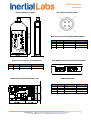
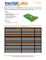
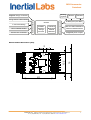
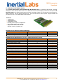
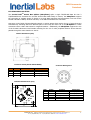
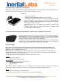
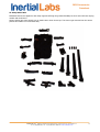
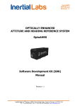
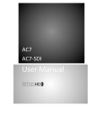
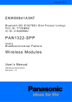
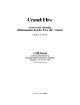
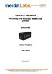
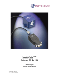
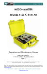
OS3D Accessories Datasheet OS3D Accessories Datasheet Revision 1.1 TM Inertial Labs, Inc Address: 39959 Catoctin Ridge Street, Paeonian Springs, VA 20129 U.S.A. Tel: +1 (703) 880-‐4222, Fax: +1 (703) 935-‐8377 Website: www.inertiallabs.com 1 OS3D Accessories Datasheet I. SENSOR BUS USB CONTROL UNIT (SB-CU-USB) The Inertial LabsTM Sensor Bus USB Control Unit (SB-CU-USB) is designed to work with the full family of Inertial LabsTM OS3D orientation sensors. The SB-CU-USB is a data acquisition system, which provides power to and receives data simultaneously via TIA/EIA-485A serial protocol and transmits data to the PC via a standard mini-USB cable. Highlights USB interface to the PC VCP interface to application software TIA/EIA-485A serial interface to sensors 3 hot-pluggable sensor chain connectors Compact and rugged metal case Supports up to 31 simultaneous devices (sensors and sensor bus extenders) • OEM version available • • • • • • Applications • Biomechanics research • Motion capture • Virtual reality simulation and training The SB-CU-USB is equipped with 3 hot-pluggable connectors able to support a combined total of up to 31 OS3D orientation sensors and sensor bus extenders (SB-Extender) simultaneously. Input supply power is able to be provided by the Inertial Labs Battery Module or an equivalent 5VDC supply. Power is then provided out to all of the connected sensor bus chains. SB-CU-USB Specifications (T=25 ºC, Vdd = 12V, unless otherwise noted) Parameter SB-CU-USB to PC interface SB-CU-USB to sensor bus interface Value USB VCP TIA/EIA-485A Units +25 -40 to +85 -40 to +85 ºC ºC ºC 5.0 to 15.0 4.5 to 5.0 3000 V V mA TIA/EIA-485A (half-duplex) 1000000 8 1 No bps bits bits - Environment Specified temperature Operating temperature Storage temperature Electrical Input supply voltage Output supply voltage Maximum output current Sensor Bus Interface Standard Baud Rate Byte Size Stop Bites Parity TM Inertial Labs, Inc Address: 39959 Catoctin Ridge Street, Paeonian Springs, VA 20129 U.S.A. Tel: +1 (703) 880-‐4222, Fax: +1 (703) 935-‐8377 Website: www.inertiallabs.com 2 OS3D Accessories Datasheet Outline Dimensions (mm) Bus Connector Mating View Bus Connector Pinout (Binder 0931118604) Num 1 2 3 4 Num Name Function Parameters GND PWR supply ground supply voltage 5.0V to 15.0V OEM Board Outline Dimensions (mm) Parameters supply voltage ground, shield A RS-485 B RS-485 4.5V to 5.0V 1 Mbps, 120Ω 1 Mbps, 120Ω OEM Board Pinout Num 4,8,12 3,7,11 2,6,10 1,5,9 TM Function PWR GND A B Mini-USB and Power Connector Mating View Power Connector Pinout (Tyco 2029030-2) 1 2 Name Name Function Parameters PWR GND A B supply voltage ground, shield A RS-485 B RS-485 4.5V to 5.0V 1 Mbps, 120Ω 1 Mbps, 120Ω Inertial Labs, Inc Address: 39959 Catoctin Ridge Street, Paeonian Springs, VA 20129 U.S.A. Tel: +1 (703) 880-‐4222, Fax: +1 (703) 935-‐8377 Website: www.inertiallabs.com 3 OS3D Accessories Datasheet II. ENHANCED CONTROL UNIT - MINICU MiniCU is designed to work with Inertial Labs orientation sensors as well as with the third-party equipment. The MiniCU is the data acquisition system, which provides power to and receives data simultaneously from multiple devices on sensor bus and transmits data via BlueTooth or other external interface. It also has build-in Li-Pol charger and DC/DC convertor for sensor bus supply. Highlights • • • • • • • BlueTooth interface TIA/EIA-485A serial interface to sensors Support 1-cell Li-Pol battery Sensor bus power supply 3V3 TTL external UART interface 16 GPIO (6 with ADC feature) LED status indicators Applications • Motion capture • Virtual reality simulation and training The device is intended for buid-in solutions. It is equipped with two expansion connectors. Three LED indicators reflect the state of the device (on or off), battery charge status. Parameter MiniCU connection diagram MiniCU wireless interface MiniCU to sensor bus interface MiniCU external interface Analog inputs Digital inputs/outputs Startup time Value BlueTooth 2.0 TIA/EIA-485A 3V3 TTL UART 6 16 <1 Units -40 to +85 -40 to +85 degC degC 4.5 to 6.5 3.0 to 5.5 5.1±0.1 500 250 V V V mA mA ±1 25 mA kOhm 3.3 16 >10 V bits KHz 1000000 8 1 No bps bits bits - sec Environment Operating temperature Storage temperature Electrical Input supply voltage (for battery charge) Input supply voltage (instead of battery) Output supply voltage (Vbus) Maximum output current (Ibus) Maximum output current (3V3) GPIO Driving capability per pin Pull up resistance ADC Input voltage range Resolution Update Rate Sensor Bus Interface Baud Rate Byte Size Stop Bites Parity TM Inertial Labs, Inc Address: 39959 Catoctin Ridge Street, Paeonian Springs, VA 20129 U.S.A. Tel: +1 (703) 880-‐4222, Fax: +1 (703) 935-‐8377 Website: www.inertiallabs.com 4 OS3D Accessories Datasheet Analog joystick [email protected] charge connector Buttons Indicators Power ON/OFF button Sensor bus connector miniCU 3xLEDs: PowerOn Charge Connect Onboard BlueTooth module PAN1321 Extender connector 1-cell LiPol battery System connector Charge status LED indicator 15 GPIO pins (6 /w ADC) 3V3 TTL UART module for external communication [email protected] power output MiniCU Outline Dimensions (mm) 16 13.5 2 24 TM Inertial Labs, Inc Address: 39959 Catoctin Ridge Street, Paeonian Springs, VA 20129 U.S.A. Tel: +1 (703) 880-‐4222, Fax: +1 (703) 935-‐8377 Website: www.inertiallabs.com 5 OS3D Accessories Datasheet II. SENSOR BUS EXTENDER-RS232 The Inertial Labs Sensor Bus Extender-20 (SB-Extender-20) is a miniature input-output controller designed to work with the OSv3 sensor bus to allow the inclusion of third-party devices into the system. SBExtender-20 has 20 digital inputs/outputs including 4 analogue inputs (w/ an internal 10-bit analogue-todigital converter) and 16 general purpose I/O. The unit also has a built-in power supply module and provides data out via a TIA/EIA-485A serial interface. Features • 16 GPIO pins • 4 GPIO/ADC pins • 3V3@500mA output • Provides power output of 5V@500mA • Uses TIA/EIA-485A serial interface • Supports the inclusion of external switches, sensors, joysticks, etc SB-Extender-20 Absolute Maximum Ratings Parameter Supply voltage (Vdd to Vss) GPIO pins voltage Value -0.3 to +6.0 -0.3 to +6.0 Units V V SB-Extender-20 Specifications (T=25 ºC, unless otherwise is noted) Parameter SBE2 to sensor bus interface Digital inputs/outputs Digital inputs/outputs or ADC Startup time Value TIA/EIA-485A 16 4 <1 Units sec -40 to +85 degC 4.0 to 5.6 3.3±2% 500 V V mA ±1 25 mA KOhm 0 to Vout 10 >10 V bits KHz TIA/EIA-485A (half-duplex) 1000000 8 1 No bps bits bits - Environment Operating temperature Electrical Input supply voltage (Vin) Output supply voltage (Vout) Maximum output current (Iout) GPIO Driving capability per pin Pull up resistance ADC Input voltage range Resolution Update Rate Sensor Bus Interface Standard Baud Rate Byte Size Stop Bytes Parity TM Inertial Labs, Inc Address: 39959 Catoctin Ridge Street, Paeonian Springs, VA 20129 U.S.A. Tel: +1 (703) 880-‐4222, Fax: +1 (703) 935-‐8377 Website: www.inertiallabs.com 6 OS3D Accessories Datasheet Communication connector pinout Num 1 2 3 4 5 6 7 8 9 10 11 12 13 14 15 16 17 18 19 20 21 22 23 24 Name Function PWR GND DDIN14 DDIN16 DDIN15 DDIN17 DAIN05 DDIN19 DAIN06 DDIN18 DAIN07 DDIN13 DAIN08 DDIN12 DDIN01 DDIN11 DDIN02 DDIN10 DDIN03 DDIN09 DDIN04 DDIN20 PWR GND Supply power Supply ground General purpose input/output pin 14 General purpose input/output pin 16 General purpose input/output pin 15 General purpose input/output pin 17 Analog 1 or digital input/output pin 5 General purpose input/output pin 19 Analog 2 or digital input/output pin 6 General purpose input/output pin 18 Analog 3 or digital input/output pin 7 General purpose input/output pin 13 Analog 4 or digital input/output pin 8 General purpose input/output pin 12 General purpose input/output pin 01 General purpose input/output pin 11 General purpose input/output pin 02 General purpose input/output pin 10/RxD General purpose input/output pin 03 General purpose input/output pin 09/TxD General purpose input/output pin 04 General purpose input/output pin 20 Supply power Supply ground Parameters 3V3@500mA up to +3V3 in up to +3V3 in up to +3V3 in up to +3V3 in up to +3V3 in up to +3V3 in up to +3V3 in up to +3V3 in up to +3V3 in up to +3V3 in up to +3V3 in up to +3V3 in up to +3V3 in up to +3V3 in up to +3V3 in up to +3V3 in up to +3V3 in up to +3V3 in up to +3V3 in up to +3V3 in 3V3@500mA - Right angle male connector SULLINS GRPB122MWCN-RC. The mating parts are SULLINS LPPB122CFFN-RC, MILLMAX 853-43-024-20 and HARWIN M50-3201245 Board drawing dimensions, (mm) Bus connection pinout (Binder 0931118604): Num 1 2 3 4 Name PWR GND A B Function supply voltage ground, shield A RS-485 B RS-485 Parameters 4.0 to 5.6V 1 Mbps, 120Ω 1 Mbps, 120Ω TM Inertial Labs, Inc Address: 39959 Catoctin Ridge Street, Paeonian Springs, VA 20129 U.S.A. Tel: +1 (703) 880-‐4222, Fax: +1 (703) 935-‐8377 Website: www.inertiallabs.com 7 OS3D Accessories Datasheet III. SENSOR BUS SPLITTER The Inertial LabsTM Sensor Bus Splitter (SB-Splitter) splits a single TIA/EIA-485 data bus into 3 TIA/EIA-485 buses. Intended for use with Inertial Labs OS3D family of sensors, the SB-Splitter supports the connection of multiple chains of devices to a single data acquisition and transmission unit such as the Inertial Labs SB-CU-W915, wireless controller, or the SB-CU-USB direct PC connection. Customers in the fields of biomechanical research or motion capture that require the use of several sensors simultaneously collecting data from different parts of the body can make use of the SB-Splitter to create convenient sensor chains that extend to targeted locations. Additionally, the SB-Splitter supports the use of the Inertial Labs Sensor Bus Extender allowing for the use of other peripheral devices whose data are passed through the same data bus to the PC. Outline Dimensions (mm) Connector Pinout (Binder 0931118604) Num 1 2 3 4 Connector Mating View Name Function Parameters PWR GND A B supply voltage ground, shield A RS-485 B RS-485 3.5V to 5.7V 1 Mbps, 120Ω 1 Mbps, 120Ω 1.5 OEM Board Dimensions (mm) 1 2 Num 3 1 2 3 4 5 13.5 4 4 3 5 Name Function Parameters B1 A1 GND PWR A2 B1 RS-485 A1 RS-485 ground supply voltage A2 RS-485 1 Mbps, 120Ω 1 Mbps, 120Ω 3.5V to 5.7V 1 Mbps, 120Ω 6 13.5 1.5 TM Inertial Labs, Inc Address: 39959 Catoctin Ridge Street, Paeonian Springs, VA 20129 U.S.A. Tel: +1 (703) 880-‐4222, Fax: +1 (703) 935-‐8377 Website: www.inertiallabs.com 8 OS3D Accessories Datasheet IV. ANKER ASTRO-3E MOBILE BATTERY PACK Anker Astro* is a line of portable external batteries designed for our modern mobile age. High capacity power and compact designs make these batteries a reliable power companion on the go. Features: • 10000mAh of capacity; • Charges one device at maximum speed or two at 3A total; • A lightweight, unassuming solution to life's daily power needs (0.59in thick). LEDs display just how much juice you've got left. Reliable lithium polymer core ensures quality, supplying you with more than 500 charge cycles during the course of its life; • Input: 5V / 1.5A; Use a 1.5A adapter (not included) for fastest charge times (8 hours); • Package contents: Anker Astro 3E External Battery, 4 adapters; USB wire, user manual, and travel pouch. V. OS3D MOUNTING PLATE AND INTERSENSE** INERTIACUBE** PRODUCTS EMULATOR I-Sense Emulator allows users to utilize the Inertial Labs™ OS3D family products as a direct replacement for Intersense InertiaCube products: IC2, IC3, and IC4. Software that is designed currently to operate with an InertiaCube product should, without any redesign, be able to accept the Inertial Labs™ OS3D data. In addition to the software interface, the standard OS3D sensor can be shipped, upon request, with an IC2 compatible mounting plate. This allows for the unit to be mounted in the same location as the IC2 unit in the application. Before You Begin When using the I-Sense Emulator it will be required to overwrite the current isense.dll that is called by your application. It is recommended prior to replacing it to either rename the file or copy the file to an alternative directory in case it is needed for future use. Additionally, it is recommended to first utilize the OS3D sensor with its native software prior to attempting to emulate the InertiaCube in your application. This will ensure that the sensor is operating properly and that the software drivers on the PC are working properly. The following software and documentation should be reviewed prior to use: Software • Inertial LabsTM SDK Lite • OS3D QuatView Demo Software Documentation • SDK Lite and Demo Software User’s Manual • SDK Initialization File Overview • OS3D Datasheet The I-Sense Emulator is designed for use on Windows based operating systems. Development testing was specifically conducted on Windows 7 but also should be applicable to Windows XP and Windows 8. Notes: * Anker Astro is a trade mark of Company ASTRO ** Intersense and InertiaCube are the trade marks of Company INTERSENSE TM Inertial Labs, Inc Address: 39959 Catoctin Ridge Street, Paeonian Springs, VA 20129 U.S.A. Tel: +1 (703) 880-‐4222, Fax: +1 (703) 935-‐8377 Website: www.inertiallabs.com 9 OS3D Accessories Datasheet Mounting plate mechanical interface drawing USB Driver Installation In order to work with the USB interface provided with the sensor shipment, it is required to install device drivers for the USB converter. Driver installations for Windows 7 and Windows XP are described below. On Windows 7 the system will recognize when the device is installed and will create an object under Device Manager. From there it is needed to select the device and do an update driver process. This process will have to be performed twice: once to install the USB Serial Converter and a second time to configure the USB Serial Port. Once completed successfully, there should be visible within Device Manager, under “Ports (COM & LPT)”, the “InertialLabs USB Serial Port” listing the COM port for the sensor. If this exists, the drivers are already installed and the device is working properly. No further installation is needed, however information of the COM port number should be kept for use within the application. Steps for installation: 1) Connect the USB device (either SB-CU-USB or USB Dongle) to the PC. 2) The system will recognize new hardware and attempt to automatically install it. In most cases, the system will not complete a successful automatic installation. 3) On the PC, go to Device Manager. This can be found under Start > Control Panel > System and Security > System > Device Manager. 4) Within Device Manager there should be a directory termed “Other devices” and within that directory the dongle should be visible as “InnaLabs Sensor NW” or “InertialLabs Sensor NW”. 5) Select the device and select “Update Driver”. 6) Select to “Browse my computer for driver software”. 7) Find the folder in which the USB Drivers can be found. This is provided with the software disk that comes with the OS3D sensor under a folder titled “USB Drivers”. 8) Windows will provide the warning “Windows can’t verify the publisher of this driver software”. Select “Install this driver software anyway”. 9) The driver should install properly stating “Windows has successfully updated your driver software”. 10) Within the Device Manager window there should still be an “Other devices” folder. Inside this directory it should show “USB Serial Port”. 11) Repeat steps 5 through 9 to setup the Serial Port. 12) Driver installation is complete. Locate the device’s COM port information in Device Manager under “Ports (COM & LPT)”. The COM port number is defined in the device name. For example, if the COM port is COM 3 the name would read “InertialLabs USB Serial Port (COM3). Make a note of the port number for later usage in the application. TM Inertial Labs, Inc Address: 39959 Catoctin Ridge Street, Paeonian Springs, VA 20129 U.S.A. Tel: +1 (703) 880-‐4222, Fax: +1 (703) 935-‐8377 Website: www.inertiallabs.com 10 OS3D Accessories Datasheet On Windows XP, when using the device for the first time, the system should launch the Windows Found New Hardware Wizard that will walk through the process of installation. The driver install process will have to be done twice to configure both the device and the USB virtual COM port. Once completed successfully, there should be visible within Device Manager, under “Ports (COM & LPT)”, the “InertialLabs USB Serial Port” listing the COM port for the sensor. If this exists, the drivers are already installed and the device is working properly. No further installation is needed, however information of the COM port number should be kept for use within the application. Steps for installation: 1) Connect the USB device (either SB-CU-USB or USB Dongle) to the PC. 2) The system will recognize new hardware and will launch the Windows Found New Hardware Wizard. 3) In the Windows Found New Hardware Wizard it will ask about driver installation. Select “No, not at this time” from the available options and click “Next” to selecte the location of the drivers manually. 4) Select “Install from a list or specific location (Advanced)” and then click “Next”. 5) Select “Search for the best driver in these locations” and browse your local folders by selecting the browse option and scrolling to the appropriate folder in which the USB Drivers can be found. This is provided with the software disk that comes with the OS3D sensor under a folder titled “USB Drivers”. 6) Click “Next” to proceed with installation. 7) It is likely that Windows will provide a warning about unsigned drivers (non-WHQL certified). Click on “Continue Anyway” to continue with the installation. 8) After completing the initial installation Windows should display a message indicated that the installation was successful. Click “Finish” to complete the installation. 9) The device is installed, but now the serial port must be configured. As such Windows will again launch the Windows Found New Hardware Wizard. 10) Repeat steps 3 through 8 to configure the Serial Port. 11) Driver installation is complete. 12) Locate the device’s COM port information in Device Manager. This can be found under Start > Control Panel > System, then under the “Hardware” tab select “Device Manager”. Select “View > Devices by Type” and the device should appear as “InertialLabs USB Serial Port (COMXX)” under “Ports (COM & LPT)”. Make a note of the port number for later usage in the application. Troubleshooting Tip If the sensor does not appear to operate correctly in the application it is possible that some of the settings within the USB Serial Port are not setup properly. This is supposed to be configured automatically in the application, but in some cases this may not happen. To check, go into Device Manager and find the “InertialLabs USB Serial Port (COMXX)” under “Ports (COM & LPT)”. Under the “Port Settings” tab, under “Advanced Settings”, check that the Latency Timer is set to 1msec. If this is not set to 1msec sensor performance may be erratic. Emulator Setup Instructions The I-Sense Emulator replaces the isense.dll on the PC with an direct emulator that then communicates to/from the OS3D sensor via the InertialLabs_SDK_Lite.dll. From that point all sensor data comes from OS3D and is presented in the user application in the same manner as the Intersense unit. Follow the below steps to setup the I-Sense Emulator: 1) Backup the isense.dll currently in use. This can either be done by renaming the file (ie. isense.dll.old) or by copying the file to a new location on the PC. To minimize confusion, it is recommended to rename the file in any case. 2) Insert the Inertial LabsTM Software Disk that came with the OS3D sensor. 3) Copy the contents from the Software Disk to the local PC. 4) From within the “Software” folder from the disk, go to the “I-Sense Emulator” folder. 5) Copy the files isense.dll, InertialLabs_SDK_Lite.dll, and InertialLabs_SDK_Lite.ini and paste them into the location on the PC where the original isense.dll was located. 6) Connect the Inertial LabsTM OS3D device to the PC. Be sure that you have the USB Drivers properly installed (See USB Driver Installation section above). 7) Set the COM-port in the InertialLabs_SDK_Lite.ini file under [WorksetNode_0]. See the document SDK Initialization File Overview under the Documents folder for more information on how to work within the initialization file. 8) The OS3D sensor is now configured and ready for use with the application. Start the application and test for proper sensor performance. TM Inertial Labs, Inc Address: 39959 Catoctin Ridge Street, Paeonian Springs, VA 20129 U.S.A. Tel: +1 (703) 880-‐4222, Fax: +1 (703) 935-‐8377 Website: www.inertiallabs.com 11 OS3D Accessories Datasheet VI. Strap-Based Suit Individual fixtures are applied to each body segment offering the greatest flexibility for those who will have varying models and model sizes. Sensor pockets are sewn directly into an Under Armor short sleeve top. The sensors get mounted into the sensor pockets and cables are routed externally. TM Inertial Labs, Inc Address: 39959 Catoctin Ridge Street, Paeonian Springs, VA 20129 U.S.A. Tel: +1 (703) 880-‐4222, Fax: +1 (703) 935-‐8377 Website: www.inertiallabs.com 12