1
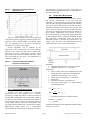
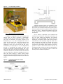
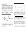
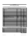
MEAM-446-2012-11 Senior Design Project - Final Report April 27, 2012 Department of Mechanical Engineering and Applied Mechanics School of Engineering and Applied Science University of Pennsylvania Philadelphia, Pennsylvania, USA TECLA: THERMOELECTRIC CHARACTERIZATION LAB APPARATUS Ellen Chang Noah Granieri Anam Omar Shengxi Yuan David Kim 1 1 1 Jennifer Lukes PhD , Robert L. Jeffcoat PhD faculty advisor instructor Department of Mechanical Engineering and Applied Mechanics, University of Pennsylvania ABSTRACT 1. INTRODUCTION AND BACKGROUND TECLA, thermoelectric characterization lab apparatus, was developed in order to characterize the performance of thermoelectric (TE) devices. TE devices utilize temperature differentials to produce voltage. TECLA is able to: vary the hot and cold side temperatures of TE devices using a scientific hot plate and a liquid cooling system; accurately measure hot and cold side temperatures using thermocouples; accurately measure the voltage output using a precision voltage sensor; apply uniform contact pressure across the surfaces of the TE device using a pneumatic actuator; allow easy access to the TE device between tests; and interface with the user via a MATLAB program to collect and process test data. TECLA produces repeatable results consistent with known TE data. Therefore, TECLA is a reliable test apparatus for research in the field of thermoelectric power generation technology. 1.1 Motivation In today’s energy-intensive world, reducing energy consumption is seen as a vitally important task. Energy generation not only has economic implications but also impacts the environment. In the U.S., 94.6 quads (quadrillion BTUs) of energy were used in 2009. Of this, approximately 54.64 quads, or 58% of the total energy use, were lost as rejected energy. Although some magnitude of energy loss due to machine inefficiencies is inevitable due to fundamental laws of thermodynamics, there has been much research in reducing the magnitude of losses by improving machine efficiency. Another way to reduce energy consumption is to capture and make use of the rejected energy, which would otherwise be dissipated into the surroundings without being used for any useful purposes. Thermoelectric generation is one emerging technology used to capture rejected energy. 1.2 Thermoelectric Generators Thermoelectric generators use a phenomenon known as the ‘thermoelectric effect’ to convert temperature differential (i.e. heat) into voltage. Thermoelectric devices are flat modules (typically with approximate dimensions of 1”×1”×0.1”) that use temperature differences between two surfaces to generate an output voltage. The voltage output MEAM-446-2012-11 page 1 Copyright © 2012 by the authors of a TE device is proportional to the temperature differential across the TE device, as well as its dimensions. Figures 1 and 2 show the construction and operation of TE devices. Figure 1 Construction of a TE Device [1] contact pressure, presence of thermal grease, etc.). However, to our knowledge, there has been little effort to aggregate the different factors identified by past studies and consolidate the measurement techniques into a single laboratory apparatus. This project aims to create a reliable apparatus by which TE devices can be characterized. 2. REQUIREMENTS AND OBJECTIVES This project aimed for TECLA to achieve the following objectives: Figure 2 Operation of a TE Device [2] 3. Simultaneous variation of hot and cold side temperatures Continuous measurement of hot and cold side temperatures and voltage output from TE device Uniform surface contact across TE device to ensure consistent heat transfer Ease of use for the operator Development of PC interface to collect and process data Ability to accommodate TE devices of various dimensions (height, width, and thickness) Minimal manual adjustment from user during testing Compact size CANDIDATE CONCEPTS 3.1 Description of Design Concepts The two basic principles needed to test a TE device are temperature difference and uniform contact between the TE device surfaces and the heat source and heat sink. These principles are identified and discussed in subsequent sections and the following three candidate design concepts were proposed to achieve them: Advantages of TE devices include compactness, solid-state operation and modularity. Because a huge proportion of waste energy comes in the form of heat, thermoelectric technology has garnered much attention, both in academia and in industry, as a promising technology for capturing waste heat. 1.3 Need for Performance Characterization Despite the promises of TE devices, their low efficiencies limit their use in practical applications. This limitation has led to active research in the field. Currently, novel thermoelectric materials and internal constructions of TE devices are being researched and developed to improve their performances and efficiencies. Furthermore, such research efforts have created a need for a reliable and consistent lab apparatus to characterize TE devices. Prior studies have explored novel testing methods for characterization of TE devices [3], identifying the variables that must be controlled to accurately characterize them (i.e. MEAM-446-2012-11 3.1.1 Liquid Baths In this design, a liquid container would be physically separated into two compartments (i.e. a wall between the two liquid baths). The temperature of each compartment would be controlled separately using a heating element for the hot side, and a heat exchanger and a pump for the cold side. In addition, a blade mixer would be installed on each side to maintain uniform temperature in each liquid bath. The two compartments would be insulated from each other but there would be a small fitting (opening) in the middle of the compartment such that a TE device could be placed inside the hole. (This would require good sealing and thermal insulation around the TE device.) Thus, with this construction, one side of the TE device would be exposed to liquid at high temperature and the other side would be exposed to liquid at a lower temperature. page 2 Copyright © 2012 by the authors 3.1.2 Applied Weights In this design, a heating element with a solid, flat surface would be used as heat source and forced convection cooling would be used for best heat rejection rate. Heat transfer between the TE device surfaces and heat source/heat sink is achieved by conduction through solid-tosolid surface contact. In order to ensure sufficient heat transfer through uniform contact, weights would be placed to apply pressure. The appropriate amount of weight would be determined by the size of the TE device and the desired pressure. Figure 3 Exploded View of the Main Parts of the TECLA Assembly 3.1.3 Pneumatic Actuator This design is identical to the previous candidate design concept (applied weights) except for the mechanism ensuring uniform contact and sufficient heat transfer. In this design, a pneumatic actuator controlled by compressed air would be used to apply pressure to the TE device surfaces. 3.2 Comparison and Downselection The liquid baths concept has two main advantages: first, perfect contact between heat source/sink and TE surfaces; second, ability to control temperatures precisely and accurately. However, it was the least feasible design due to limitations in liquid temperatures, extensive insulation of electronics from liquids, sealing of liquid containers, and perhaps most importantly, ease of use. This concept would likely be a apparatus for research use (i.e. The user would not be able to switch in and out the TE device between tests easily). The applied weights concept has the advantage of being much neater in its construction compared to the liquid baths concept. It is also able to control and measure hot and cold side temperatures with proper placement of measurement devices. However, it has a critical disadvantage of not being able to continuously vary the pressure on TE devices and requires the user to manually place weights (that would be quite cumbersome to handle for most users) for each test. The pneumatic actuator concept, which is a modification of the applied weights concept, was ultimately chosen as a more elegant and neater solution with the ability to provide variable pressures for different TE devices and greater usability for the end user. 4. The remainder of this section is used to provide the analyses involved in the design decisions for different components of TECLA. 4.2 Contact Pressure During preliminary testing of TE devices, we learned that there is a strong correlation between output voltage and force exerted on the TE device. The plot in Figure 4 provides testing data showing the effect of an applied pressure on the output voltage of a given TE device at a constant temperature difference. Figure 4 shows the results of the test that was done to show the dependence of voltage on applied pressure. This test was performed by heating the TE device to a steady-state condition, varying the pressure applied on the TE device, and subsequently measuring the output voltage. DESIGN DESCRIPTION 4.1 Overall System Design In TECLA, the TE device whose performance is being characterized is “sandwiched” between a heat source and a heat sink, which have smooth and flat surfaces. Sufficient and consistent contact pressure is applied to the TE device during the test. Temperature and voltage are measured and processed on a PC. Figure 3 shows the overall construction of TECLA. MEAM-446-2012-11 page 3 Copyright © 2012 by the authors Figure 4 Dependence of Voltage Output on Applied Pressure this turned out to be false; in section 5 of this paper, we discuss additional instrumentation that was implemented to meet this requirement. 4.4 The test of variable weights on the TE device displayed an asymptotic behavior suggesting a minimum pressure was required to achieve optimal results. The optimal weight may vary depending on the TE device, stressing the importance of a variable pressure supply. Temperature Measurement In order to characterize TE devices accurately, precise and accurate measurements of hot and cold side temperatures of the TE device must be obtained. This goal was achieved by placing an aluminum block (with thickness 0.25”) above the hot plate and below the heat sink. These aluminum conduction blocks transfer heat from the heat source, across the TE device, and into the heat sink. They also allow easy temperature measurements at the surfaces of the TE device. Temperatures at the surfaces of the TE device were measured by placing thermocouples inside slots on both conduction blocks. Analytical calculations showed that temperature measurements inside the block are sufficiently accurate to measure the temperatures at the surfaces of the TE device. The calculation done for the conduction block for the hot side is shown below: Pressure dependence can be explained by the microscopic surface imperfections seen at the interface between the TE devices and heat sources. Small voids filled with air create a high thermal resistance, which decreases the heat transferred from the heat source to the heat sink through the TE device. This phenomenon is illustrated in Figure 5. [4] Figure 5 4.3 Schematic of Micro-Scale Surface Roughness and Asperities Dimensions: Aluminum block thickness: L=0.25in=0.00635m Thermal conductivity (k) = 237 W/m*K Assumptions: Perfect contact between the aluminum block and the hot plate due to application of thermal grease Temperature of the hot plate: Tplate = 250 ºC Power input of the hot plate: q’’ = 1000 Watts Steady State Heat only flows in the vertical direction Slot for the thermocouple is very small compared to the aluminum block k × (T -T ) L plate TE.hot 237 1000 = .(250 -T TE,hot ) 0.00635 q'' = Small Voltage Measurement Accuracy and high resolution are desirable characteristics for a lab apparatus. This is especially important for voltage measurement for TECLA because of the small order of magnitude of the voltage that is produced by TE devices. For accurate measurement, the resolution of the measurement device must be finer than the change in voltage output between consecutive measurements. This was initially deemed feasible with a commercially available high-precision voltage sensor and a corresponding microcontroller. However, during our prototype realization, MEAM-446-2012-11 x Î [0, 0.00635m] (thickness of conduction block) and when x = 0.00635m: T TE,hot = 249.97°C Temperature distribution of the aluminum conduction block is shown as T(x) below: page 4 Copyright © 2012 by the authors T (x) = Tplate - Tplate -TTE.hot L T(x) = 250 - 4.72x, x Î [0, 0.00635m] Note, x = 0 at the hot plate and x = 0.00635m at the surface of the TE device. Therefore, the temperature difference between the hot plate surface and the TE device surface is negligible, at only 0.03 degrees Celsius. 4.5 User Friendliness and Safety A fundamental requirement for TECLA was the facility with which TE modules could be swapped in and out. In order to achieve this goal, a design that allowed the user to lift the heat sink unit and easily place a TE device below it was implemented. The heat sink unit was retrofitted to a custom machined aluminum holder that allowed for a hinge to be attached to it such that the user would be able to 'open' and ‘close’ the unit to place and remove a TE device. Figure 6 shows a diagram of this mechanism. Figure 6 PROTOTYPE REALIZATION 5.1 Figure 7 Integrated Cooling Unit with Heat Exchanger and Pump Opening and Closing of Retrofitted Cooler Unit When testing a TE device using TECLA, a significant amount of heat is generated to reach temperatures as high as 250 degrees Celsius. In order to make this hot environment safe for the user, a transparent enclosing box was made. The user would be able to observe the test without being directly exposed to this heat. 5. A copper CPU cooler with a gold plated conductive surface (CPU-300-V10, Koolance) was retrofitted to cool the cold side of the TE device. An integrated liquid cooling system (EXT-440CU, Koolance) was used with the copper cooler. The cooling system is able to cool the TE device down to approximately 30 degrees Celsius over time; a wide range of temperature difference can thus be created, enabling complete characterization of the performance of the TE device. The heat sink was retrofitted with custommachined parts for seamless integration into the TECLA. The liquid cooling system circulates the coolant into the heat sink, providing additional cooling capability. The liquid cooling system, shown in Figure 7, is a combination of a heat exchanger, a pump, and a reservoir. The fan power and the coolant pump speed can be controlled to vary the rate of heat rejection. Overall Prototype Description A commercially available scientific hot plate (Cimarec) was used to raise the temperature of the hot side of the TE device. The hot plate is capable of achieving temperatures up to 450 degrees Celsius, which is beyond 250 degrees Celsius, the upper limit for most TE devices. MEAM-446-2012-11 A pneumatic actuator, along with a set of valves, is actuated by compressed air to apply uniform contact pressure on the TE device. Thermocouples are used to measure the temperatures of both the hot and cold sides of the TE device. A precision voltage sensor, with appropriate circuits, is used to measure the voltage. Both temperature and voltage data are collected by corresponding microcontrollers and sent to the PC. Finally, a MATLAB program stores the data for further processing while providing a user-friendly interface for the control of the apparatus. page 5 Copyright © 2012 by the authors Figure 8 Final Assembly of TECLA Aluminum conduction blocks were machined to allow for temperature measurements near the TE device surfaces. These blocks were machined with the finest possible surface finish for optimal heat transfer capabilities. Each conduction block had 1” deep, ⅛” diameter holes drilled into the sides so that thermocouples could be inserted for temperature measurement. 5.2 Manufacturing of Components A number of components were custom-machined for TECLA. First, in order to integrate a commercially available heat sink unit into TECLA’s assembly, a multipart mount was machined. The mount consisted of an aluminum tray (4” x 5”), with a rectangular slot cut out to expose only the copper plate of the heat sink unit when placed on the TE device. An aluminum fastener was machined to secure the top of the heat sink unit to the aluminum tray. An acrylic plate (6” x 6”) was designed and laser-cut to accommodate the mount and heat sink assembly, an aluminum counterweight handle, and a steel hinge. The other end of the hinge was attached to a slider machined to facilitate the vertical movement of the heat sink unit. The slider had two drilled out through-holes that were fitted with linear bearings to enable smooth vertical movement along the aluminum shafts used as guide rods. Diagrams of the machined parts (shaded areas) are shown in Figure 9. Figure 9 All of TECLA’s components were assembled and combined on a wooden base. Wood was selected due to its low cost, light weight, high durability, and aesthetic qualities. The most challenging task at this stage was attaching the two aluminum shafts so that the heat sink unit would be able to slide seamlessly along these shafts. After much consideration, the shafts were tapped and screwed into the wooden base with wood insert screws. This method was chosen to ensure that the shafts remained as vertical as possible. In order to make TECLA safe for the user, an enclosing box made of acrylic was laser-cut and attached to the wooden base with a steel hinge. Figure 10 shows the assembly of these machined components. Schematic Diagrams of CustomMachined Parts MEAM-446-2012-11 page 6 Copyright © 2012 by the authors Figure 10 Easy Access to TE Device 5.4 Contact Pressure For TECLA, a pneumatic actuator was installed to apply a constant pressure on the TE device, with a precisely machined flat aluminum piece that was mounted to the end of the actuator. This ensures an even distribution of pressure over the TE device surface area during tests. Figure 12 shows the schematic diagram of the pressure system. The 2-way pneumatic actuator has two inputs, one of which extends the shaft while the other retracts it. The three-way valve directs compressed air from a single source into the appropriate input port to either extend or retract the actuator shaft. Figure 12 5.3 Configuration Used for Contact Pressure: Schematic and Picture Thermal Grease for Heat Transfer During our prototype fabrication, we learned the importance of thermal grease for effective heat transfer. For instance, the heat rejection rate of the heat sink is significantly improved by application of thermal grease within its assembly. Figure 11 exemplifies the strong effect thermal grease had on TECLA’s performance. Figure 11 Effect of Thermal Grease on Heat Sink Performance 5.5 Without thermal grease, the maximum temperature and rate of temperature increase of the cold side were significantly greater than analogous values with thermal grease applied. Using thermal grease, cold side temperature varied only 1-2 degrees Celsius during the length of a test even when hot side temperature exceeded 100 degrees Celsius. Thus, for effective heat transfer, thermal grease was applied at every contact interface. MEAM-446-2012-11 Temperature Measurement Hot and cold side temperatures are measured with Ktype (Phidget) thermocouples. They have a range of -50 degrees Celsius to 450 degrees Celsius and an accuracy of ±0.75 degrees Celsius. Typical noise of 0.02 degrees Celsius found in the Phidget temperature sensor accounts for some of the error in the data. 5.6 Small Voltage Measurement: Output Voltage Amplification After the TECLA prototype was initially assembled, the voltage measurement exhibited a stepping effect in which the voltage remained at a certain level for a length of time, and then “jumped” to another level instantaneously. Further page 7 Copyright © 2012 by the authors investigation revealed that the precision voltage sensor used to measure the voltage had a resolution of 0.07 volts. The change in voltage with each measurement was too small for the voltage sensor to detect. In order to ensure that even the smallest changes in voltage could be recorded, the output voltage was amplified before being read by the voltage sensor. The voltage was then scaled down in the MATLAB program. The voltage outputted by the TE device was run through an operational amplifier (op-amp) circuit, shown in Figure 13, and amplified by a factor of R2/R1. Using an LM358 op-amp, and two 100k ohm and 15k ohm resistors, the voltage was amplified by approximately 6.7. This gain was decided by the voltage range produced by TE device and the op-amp voltage supply. The op-amp cannot amplify a voltage beyond its supply voltage. Hence, the amplified voltage could not exceed 30V. The maximum recorded value of TE voltage output was approximately 2.2 volts. With an amplification of 6.7, this provided a safety factor of 2.0. Figure 13 Op-Amp Circuit Used for TECLA Figure 14 The accuracy of voltage measurement is affected by the op-amp circuit and the voltage sensor. Calibration of the opamp circuit revealed that it has an output range of 0V to 30V and an accuracy of ±0.2V. The Phidget voltage sensor has a range of -30V to +30V with a maximum error of ±0.6V. The total accuracy of the voltage measurement is, therefore, ±0.8V. After scaling it down, the accuracy is within ±0.09V. 5.7 Ideally, the amplification should be R2/R1, but in actuality the amplification includes a gain and an offset. Data points were gathered by inputting known voltages into the circuit and measuring the output voltage. The relationship is linear. With a linear fit, the gain (slope of the line) and the offset (y-intercept) were found and accounted for in the MATLAB code. The data used for this calibration is plotted in Figure 14. MEAM-446-2012-11 Calibration of Op-Amp Data Collection and Processing Both temperature and voltage data are collected by corresponding microcontrollers and sent to the MATLAB program. When starting a test, the Graphical User Interface (GUI) provides the user with two options: 1) start test and stop when all readings stabilize; 2) start test and stop manually, as shown in Figure 15. During a test, the GUI displays hot and cold temperatures, temperature difference, and voltage readings in real time. At the end of each test, the GUI produces plots that help the user visualize the performance of the TE device. One of the plots produced is voltage output as a function of temperature difference, which shows the direct relationship between temperature difference and voltage. Another plot is temperatures and voltage as a function of time, which allows the user to evaluate the transient behavior of the TE device. In addition, the GUI saves all temperature and voltage data as a .out file for access in the future. The GUI code is relatively simple and can be easily modified by experienced MATLAB users. page 8 Copyright © 2012 by the authors Figure 15 TECLA’s GUI Figure 17 show comparison between test results obtained from TECLA’s measurement of a TE device and published values from Hi-Z [5] for their similarly dimensioned product. Figure 17 6. Comparisons between TECLA Results and Published Value EVALUATION AND TEST Multiple tests were conducted to ensure reliability and accuracy of TECLA. Voltmeter measurements of output voltage to check consistency of TECLA measurements were used as a first order verification. Additionally, the TE device was connected to an oscilloscope to verify accuracy of previous TECLA measurement data. Both tests verified the accuracy of TECLA voltage measurements. Also important to the viability of any test apparatus is repeatability. Multiple tests using the same TE device under identical conditions were conducted to check for similar results. TECLA proved repeatable, as measured values of voltage under identical operating conditions never deviated more than 20mV, or 3%. Results of successive tests are presented in Figure 16. Figure 16 Repeatability Tests Finally, results from published values for TE devices were compared to tests from TECLA. High-end suppliers of TE devices provide data for their products allowing direct comparison between test results of open circuit voltage from TECLA and known values. Data presented in MEAM-446-2012-11 It should be noted the TE device used for testing was a generic, non-brand module with similar dimensions to the Hi-Z 2 (1.15’’ x 1.15’’ x 0.2’’); the voltage outputs of currently available TE devices, with identical operating conditions, depend almost exclusively on the dimensions because the materials used and the internal construction are similar across manufacturers. Thus the results, which are expected to be similar although not necessarily identical, prove the reliability and accuracy of TECLA. 7. DISCUSSION Overall, TECLA’s current design satisfies the basic requirements of a TE device characterization apparatus. Particularly successful aspects include: guaranteed surface contact with variable pressures, efficacy of heat sink and heat source to create large temperature differentials, usability of entire device (ease of swapping in/out TE devices, set up of test, GUI, etc.), and accuracy and reliability of measurements. Although the fundamental mechanism behind the characterization is quite straightforward and not novel to both industry and academia, there had been no testing instruments available for use in research. It is, in fact, unclear how TE device performances are reported by manufacturers. The testing procedure for TE device performances are largely unreported; therefore, many reports of TE device performances seem vague and, to a certain extent, quite arbitrary. TECLA is a successful example of a custom-built lab apparatus for TE device characterization. In addition, in this paper, we have reported the construction of the machine, measurement techniques, and verifications of TECLA. Therefore, we believe TECLA is a successful example of design and implementation of an integrated system for researchers who need reliable and consistent characterization of TE devices. page 9 Copyright © 2012 by the authors 8. CONCLUSIONS AND RECOMMENDATIONS TECLA successfully fulfills the requirements laid out for this project. However, for more comprehensive performance characterization we suggest two additions/modifications that can be made to the system. First, a precise measurement of the pressure/load applied by the actuator may prove useful. Currently, the reading on the pressure gauge is taken as the pressure applied on the TE device. A direct measurement at the point of mechanical contact would provide a more accurate measurement of this pressure. Second, power output and efficiency, in addition to voltage output, may be measured by adding modular/variable load resistances. Both of these additions can be implemented with relative ease and simplicity and will make TECLA, which is already fully functional in its current construction, more comprehensive in its ability to characterize TE device performance. 9. REFERENCES [1] Scansen, Don. "Thermoelectric Energy Harvesting." Digi-Key. Web. 23 Apr. 2012. <http://www.digikey.com/us/en/techzone/energyharvesting/resources/articles/thermoelectric-energyharvesting.html>. [2] "Thermoelectric Generator." Thermoelectric Generator. Web. 23 Apr. 2012. <http://www.tegpower.com/>. [3] Ciylan, B., and S. Yilmaz. "Design of a Thermoelectric Module Test System Using a Novel Test Method." International Journal of Thermal Sciences 46.7 (2007): 71725. Web. [4] Zou, Mingqing, Boming Yu, Jianchao Cai, and Peng Xu. "Fractal Model for Thermal Contact Conductance." Journal of Heat Transfer 130.10 (2008): 101301. Web. [5] "Hi-Z 2 Thermoelectric Module." Hi-Z Technology, Inc. Web. <http://hi-z.com/documents/HiZ_Module_Properties.xls>. MEAM-446-2012-11 page 10 Copyright © 2012 by the authors APPENDIX A MATERIALS AND COST SUMMARY The materials cost of the prototype TECLA was approximately $2,380, of which $1,338 was associated with items made available on loan or from MEAM supplies. $1,252 of the $1500 MEAM authorized budget was spent leaving a surplus of $248 EMBEDDED, EXPENDED, and CONSUMED ITEMS qty Description Cooling System (heat sink, tubing, pump/heat exchanger, coolant, 1 power adapter) 1 Scientific Hot Plate 1 Air Compressor 4 Thermocouples 1 Temperature Phidget 1 Voltage Phidget and interface kit 1 Artic Silver 5 Thermal Paste, 12g 2 Swiftech HydrX Coolant 1 Acrylic Cement and Syringe Applicator 3 Steel Shaft 1/4" OD, 7" Length 1 Steel Shaft 1/8" OD, 4" Length 1 Anodized Aluminum Shaft, 3/8" Diameter, 18" Length 1 SS Flat Head Machine Screw, 8-32 Thread, 1.25" Length 1 Pneumatic Actuator 20 Blue Polyurethane Tubing, 1/4" OD, 0.16" ID 10 Clear Polyurethane TubingTubing, 1/2" OD, 3/8" ID 2 1/4" Tube Adapter 10-32 UNF 3 1/4" Tube Adapter, 3/8" NPT 1 1/4" Tube Fitting Adapter, 1/4" NPT 1 3-Port Brass Ball Valve 2 Aluminum Threaded Pipe Tee, 3/8" Pipe Size and Pipe nipple 2 ASME Pop-Safety Valve, 3/8 NPT Male, 150 PSI 2 6" SS Surface Hinge 2 3/8" Linear Bearing 4 External Retaining Ring for Linear Bearing for 5/8" OD 1 Steel Draw Latch, Pack of 5 1 Wood block, Red Oak Source Koolance McQueen.com BrandNewEngines Phidgets Inc. Phidgets Inc. Phidgets Inc. Coolerguys.com Coolerguys.com Tap Plastics McMaster McMaster McMaster McMaster McMaster McMaster McMaster McMaster McMaster McMaster McMaster McMaster McMaster McMaster McMaster McMaster McMaster School of Design Cost/item $ $ $ $ $ $ $ $ $ $ $ $ $ $ $ $ $ $ $ $ $ $ $ $ $ $ $ Total 354.60 189.00 141.16 11.65 97.00 75.77 20.50 3.95 25.30 4.67 2.99 23.86 12.59 60.45 0.89 1.10 3.23 3.60 2.83 35.75 9.13 6.12 7.46 17.63 0.34 8.88 5.00 Total Cost $ $ $ $ $ $ $ $ $ $ $ $ $ $ $ $ $ $ $ $ $ $ $ $ $ $ $ 354.60 189.00 141.16 46.60 97.00 75.77 20.50 7.90 25.30 14.01 2.99 23.86 12.59 60.45 17.80 11.00 6.46 10.80 2.83 35.75 18.26 12.24 14.92 35.26 1.36 8.88 5.00 $ 1,252.29 RECOVERABLE ITEMS and CAPITAL RETAINED BY MEAM qty 1 1500 30 1 1 Description Generic Thermoelectric device ¼” Clear Acrylic Aluminum bar stock Assorted screws, nuts, wires, resistors, op-amps, standoffs Laptop Computer Source Ebay MEAM Supplies MEAM Supplies MEAM Supplies Noah Granieri Cost/item Total Cost $ 20.00 $ 20.00 $ 0.06 $ 90.00 $ 0.73 $ 21.90 $ 6.00 $ 6.00 $ 1000.00 $ 1000.00 Total MEAM-446-2012-11 page 11 $ 1,137.90 Copyright © 2012 by the authors APPENDIX B TECLA USER MANUAL 1. Make sure all components requiring power are plugged in (hot plate, cooling unit) 2. Open box and place thermoelectric device on hot plate. Make sure hot side of TE device is face down (i.e. on conventional TE devices when hot side is faced down red lead is on right, black lead is on left). 3. Close heat sink unit on top of TE device. 4. Plug leads of TE device into lead labeled “Thermoelectric” coming out of circuit box. 5. Plug batteries/power supply into lead labeled “Power in” coming out of circuit box. Be sure to plug appropriate power/ground into the leads - failing to do so will BREAK the OP-AMP. 6. Connect the 2 USBs coming out of circuit box into laptop/desktop. 7. Open MATLAB and change to appropriate directory where GUI and corresponding files are saved. 8. Type “GUI” in command window to run the GUI and initialize all parameters. 9. Close box of TECLA and secure latches. 10. With compressed air supply connected to actuator, turn 3-way valve to position labeled “OUT.” This will extend the actuator. Make sure to pull the release valve of whatever line you are NOT supplying air to - this releases residual pressures from previous use of the actuator! Amount of pressure can be controlled via the compressed air supply. 11. Power on cooler to desired pump and fan speeds (speeds vary from 1-10 and are controlled using buttons on the cooler). 12. Power on hot plate to desired temperature. 13. Start taking measurements using GUI. Select desired option to manually stop or run until stable. 14. Once test is complete, power off all units. 15. To retract the actuator, turn the 3-way valve to position labeled “IN”. If it does not retract, pull release valve of “OUT” line to get rid of residual pressure in the tubing. Note: - Current MATLAB code was run on 32-bit version. There have been issues running the GUI on the 64-bit version of MATLAB. The current code has not yet run successfully on 64-bit. We advise running the current GUI on 32-bit. - In order to make this procedure easier on the user, a video demonstration of how to use TECLA will be provided to the user. MEAM-446-2012-11 page 12 Copyright © 2012 by the authors


![The Pinball Interface Gadget [PIG] User Manual](http://vs1.manualzilla.com/store/data/005778998_1-4ef7b51c0feccb7069db304928e0e19c-150x150.png)