1
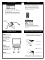
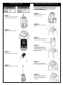
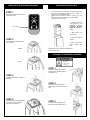
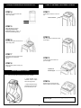
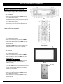
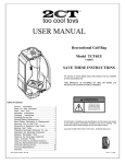
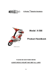
TM
USER MANUAL
Recreational Golf Bag
Model TCT6EU
V29T
SAVE THESE INSTRUCTIONS
For service or more details about this product visit our website
at www.toocooltoys.net
THIS PRODUCT IS COVERED BY ONE OR MORE U.S
PATENTS OR OTHER PATENTS PENDING.
Table of Contents
WARNING
Service Information………………....................... 1
Rules for Safe Operation……….……...………... 2
Know Your Unit…………………………………… 3
Assembly Instructions………….…………………. 3
Charging Instructions……………....................... 4
Powering On the Unit……………………………..... 4
Remote Battery Replacement……………………... 4
Main Battery Information & Replacement…...…. 4
Securing Unit on Golf Cart…...………..………… 5
Removing or Replacing Logo Patch.................... 5
Ejecting Golf Clubs……………………………...... 6
Preparing Beverage Dispenser for use………… 6
Operating the Beverage Dispenser……….……. 7
Keeping Beverages Cold………………………... 7
Cleaning the Beverage Dispenser……………… 7
Using Umbrella Pocket…………………………... 8
Using TV Antenna and Stereo Antenna……......... 8
Using the Stereo/DVD/CD/TV and Monitor………. 9
Care and Cleaning of Unit………………………….10
Technical Specifications……………………………10
Warranty…………………………………………......10
Document Number 108-06
All information. illustrations and specifications in this manual are based
on the latest product information available at the time of printing. We
reserve the right to make changes at any time without notice.
Copyright © 2006 TOO COOL TOYS, INC., All Rights Reserved.
Rev1 (12/06)
RULES FOR SAFE OPERATION
READ ALL INSTRUCTIONS BEFORE OPERATING
AUDIO AND VIDEO SAFETY WARNINGS:
• Mobile DVD Player is a class I laser product. However this
mobile DVD player uses a visible/invisible laser beam which
could cause hazardous radiation exposure if directed.
• Be sure to operate the mobile DVD player correctly as
instructed.
• Do not open covers and - DO NOT repair yourself. Refer
servicing to qualified personnel.
• To reduce the risk of fire or electric shock, DO NOT expose this
equipment to rain or moisture.
• This device is intended for continuous operation.
• Read the instructions carefully. Be familiar with the controls and
proper use of the unit.
• Children must not use the unit, except teens guided by an adult.
• Do not place head over top of unit when ejecting Golf Club – Be
aware of the risk of injury to head or face.
• Always make sure area around bag is clear when ejecting a golf
club.
• High wind may carry golf club when ejected from unit.
ELECTRICAL SAFETY WARNINGS
OTHER SAFETY WARNINGS:
DANGER! RISK OF ELECTRICAL AND FIRE HAZARD. MAY
RESULT IN DEATH, SERIOUS INJURY, SHOCK OR BURNS.
• Store the unit in a dry place.
• Store the unit in an upright position.
• Secure the unit properly on any golf cart – follow ALL
instructions.
• Use caution when lifting the unit.
• Keep these instructions. Refer to them often and use them to
instruct other users.
• Save these instructions.
TO HELP REDUCE THIS RISK:
• Unit is an electrical device - care must be taken when charging the
battery. Follow all battery charging instructions.
• DO NOT short-circuit or disassemble the battery. A short-circuit may
cause severe damage to the battery.
• DO NOT drop, hit or otherwise abuse the battery. This behavior may
result in the exposure of the cell contents, which are corrosive.
FCC SAFETY NOTICE:
• DO NOT expose the battery to moisture or rain. Keep battery away
from fire or from other sources of extreme heat. Do not incinerate.
• This device complies with Part 15 of the FCC Rules.
Exposure of battery to extreme heat may result in an explosion.
•
Operation of this device is subject to the following two
• DO NOT disassemble charger. Take it to a qualified service person
conditions:
when service or repair is required. Incorrect reassembly may result
• This device may not cause harmful interference, and
in a risk of electric shock or fire.
• this device must accept any interference received, including
• DO NOT expose charger to rain, snow, water, gas, oil, etc.
interference that may cause undesired operation.
• DO NOT operate charger if it has received a sharp blow, been
• This equipment has been tested and found to comply with the
dropped, or otherwise damaged in any way; take it to a qualified
limits for a Class B digital device, pursuant to Part 15 of the FCC
service person.
Rules. These limits are designed to provide reasonable
• DO NOT block air holes in top or bottom of charger.
protection against harmful interference in a residential
• Charger MUST be grounded to reduce risk of electric shock.
installation. This equipment generates, uses and can radiate
• The plug MUST be plugged into an outlet that is properly installed
radio frequency energy and, if not installed and used in
and GROUNDED in accordance with all local codes and ordinances.
accordance with the instructions, may cause harmful
interference to radio communications. However, there is no
guarantee that interference will not occur in a particular
installation. If this equipment does cause harmful interference to
radio or television reception, which can be determined by turning
the equipment off and on, the user is encouraged to try to
correct the interference by one or more of the following
measures:
• Reorient or relocate the receiving antenna.
• Increase the separation between the equipment and receiver.
• Connect the equipment into an outlet on a circuit different from
that to which the receiver is connected.
• Consult the dealer or an experienced radio/TV technician for
help.
• This equipment has been certified to comply with the limits for a
Class B computing device, pursuant to FCC Rules. In order to
maintain compliance with FCC regulations, shielded cables must
be used with this equipment. Operation with non-approved
equipment or unshielded cables is likely to result in
interference to radio and TV reception. The user is cautioned
that changes and modifications made to the equipment without
the approval of manufacturer could void the user’s authority to
operate this equipment.
2
KNOW YOUR UNIT
ASSEMBLY INSTRUCTIONS
Step 4
Step 1
Install the Carry Strap by attaching the
single quick clip to the top ring and
attaching the two lower quick clips to the
bottom anchor rings.
Install the battery,
springs first and up,
into the access door.
Step 2
Step 5
Open the battery door by sliding the
latch. Swing open.
Plug battery charger into
Charger Port.
Step 3
Latch
Orient the battery with spring
contacts toward the top of the
battery.
Step 6
Plug Charger into wall outlet
and charge for 12 hours.
Springs up
3
CHARGING INFORMATION
REMOTE BATTERY REPLACEMENT
The remote unit utilizes a standard CR2032 lithium
button cell. In normal use, it will provide 1 to 2 years of
operation. To replace the battery, remove the access
cover by pressing down firmly on the label area and
sliding it off. Once the unit is open, remove the battery
by sliding it from beneath the holder.
Charger should
only be used in
grounded outlet
•
•
•
•
Charger should only be used in grounded outlet.
When the Charger is plugged in to a wall outlet the
Green light will illuminate.
A completed charge cycle is indicated by the red LED.
The charger can be left on the battery without damage,
and keeps the battery fully charged, ready for use at all
times.
Green LED
Power On
There may be the risk of explosion if the battery is
replaced by the wrong type. Replace it with the same
type of battery while observing the polarity shown in the
adjacent figure.
Red LED
Battery
Charged
POWERING ON THE UNIT
MAIN BATTERY INFORMATION & REPLACEMENT
Step 1
In order to provide power to the
unit it is necessary to activate
the Main Power Switch.
Locate the switch beneath the
Stereo and Video Access
Zipper and just below the
stereo on the left side.
Step 2
•
Under normal operating conditions, four or five years of
dependable service life can be expected in stand-by
applications, or between 200 and 1000 charge/discharge
cycles depending on the average depth of discharge.
•
To replace battery:
1. Remove from unit
Press switch to ON position.
2. Remove springs.
Step 3
In order to allow the remote
control to function, it is
necessary to activate the
Ejector Safety Switch. Locate
the switch to the right of the
Main Power Switch.
Step 4
3. Slip pull tab off of the
battery
Main
Power
Switch
Ejector
Safety
Switch
4. Reverse to reinstall
Press switch to ON position.
Replacement batteries are available at www.toocooltoys.net or
your local battery retailer. Replace only with exact size battery.
4
SECURING THE UNIT ON A GOLF CART
SECURING THE UNIT ON A GOLF CART cont.
INSTALL UNIT ONLY ON DRIVER SIDE
OF GOLF CART
STEP 4
Open the cam buckle on golf
cart.
STEP 1
Lift unit onto DRIVER SIDE of golf
cart.
STEP 5
Locate the Supplemental Cart
Strap on left side of unit. Pass
the Strap through the cam buckle
on the golf cart.
STEP 2
Locate Golf Cart Strap
Securing Rings on the right
side of unit. Feed golf cart
strap through openings of
both Securing Rings.
STEP 6
Pull the Strap tightly and close
cam buckle.
STEP 3
Loop strap back through
opening of rear Securing
Ring and pull tightly.
REMOVING AND REPLACING LOGO PATCH
•
•
STEP 4
Logo Patch is attached to unit with velcro material and can
be removed or replaced as needed.
To remove Logo Patch:
1. Pull up one end of
Logo Patch and pull
gently
Loop strap back through outer opening of the front
securing ring only, and pull tightly.
2. To install, place
patch in position and
tuck under flap
Replacement or custom Logo Patches are available at
www.toocooltoys.net.
5
EJECTING GOLF CLUBS
Use Caution
when ejecting
Golf Clubs
PREPARING BEVERAGE DISPENSER FOR USE
BEVERAGE DISPENSER CAN BE USED WITH
ALL BEVERAGE TYPES – DO NOT USE ICE
INSIDE BEVERAGE TANK
Do place head
over ejector tubes
when operating
STEP 1
Open zipper access to Beverage
Tank and remove tank.
STEP 1
Insert club shaft into ejection tube and
press down until the spring latches
STEP 2
Press quick disconnects to remove
hoses.
STEP 2
Identify ejection tube of selected
club.
STEP 3
Remove cap and fill tank to no more
than 2” from top. Close cap tightly.
MAX FILL LINE
STEP 4
Reconnect color coded hoses.
Connect black fitting on hose to
black fitting on tank. Connect red
fitting on hose to red fitting on tank.
Close zipper access.
STEP 3
Press appropriate button on remote.
STEP 5
Slide pump handle access door
open and pull up the pump handle.
STEP 4
Prepare to catch club as it is ejected.
STEP 6
Pump the handle until the tank is
pressurized. Store handle in the
down position and replace the
access door.
6
OPERATING THE BEVERAGE DISPENSER
KEEPING BEVERAGES COLD
•
•
STEP 1
Depress and hold the UP button on
the remote control.
•
•
Your unit comes with a Cool Jacket for the Beverage Tank.
The Cool Jacket will keep beverages cold – there is no
need for ice in the Beverage Tank.
Prepare the Cool Jacket in advance of using your unit.
Place it in a freezer overnight to ensure best results.
To remove the Cool Jacket
1. Remove Tank from
unit according to the
directions in Section:
Preparing Beverage
Dispenser For Use –
page 5
Press and hold
2. Slide Tank out of
Cool Jacket.
3. Place Cool Jacket in
Freezer.
STEP 2
Press button until tap dispenser is
fully extended.
4. When Cool Jacket is
frozen, replace over
tank.
WRONG
Replacement or Cool Jackets are available at:
www.toocooltoys.net.
CLEANING THE BEVERAGE DISPENSER
Thoroughly clean
Beverage
Dispenser after
each use
RIGHT
STEP 1
Remove Beverage Tank from unit
and disconnect the RED pressure
hose fitting only.
STEP 4
Pull tap handle forward to dispense
beverage
STEP 2
Open Dispenser Tap Handle to
allow Supply Tube to drain back into
tank.
STEP 5
STEP 3
Depress and hold the DOWN button
on the remote control until tap
dispenser is fully stowed.
Disconnect BLACK supply hose
fitting and empty Beverage Tank.
7
CLEANING THE BEVERAGE DISPENSER Cont
USING TV ANTENNA AND STEREO ANTENNA
STEP 4
STEP 1
Fill bottom two inches of tank with
warm soapy water.
Locate Stereo Antenna on front of
unit.
Stereo Antenna
2”
STEP 5
Follow directions in section:
Preparing the Beverage
Dispenser for Use – page 5, to
reconnect the Beverage Tank.
STEP 2
Pull up on Stereo Antenna and raise
to full height.
STEP 6
Pressurize the system and flush out
all the soapy water.
STEP 7
Refill bottom two inches of tank with
clear water and repeat steps
5 and 6.
STEP 3
Locate TV Antenna Pocket and
open the zipper.
STEP 8
Allow tank to dry before closing cap
for storage.
TV Antenna
Pocket Zipper
USING UMBRELLA POCKET
•
Your unit comes with a pocket for carrying an umbrella.
1. Insert umbrella in the
Umbrella Pocket located
above the Logo Patch.
STEP 4
Remove both TV Antennae and
adjust to obtain best picture quality.
2. Slide umbrella through
pocket and place the tip in
the Umbrella Tip Anchor.
NOTE: Television reception will vary greatly by location and
signal strength.
8
USING THE STEREO/DVD/CD/TV AND MONITOR
Refer to Stereo and Monitor instructions for complete
information regarding the operation of these units.
Refer to diagrams at right for Stereo and Stereo Remote
button identification.
• To use the Radio
• Power on the Stereo by pressing the POWER button (#1)
or use Stereo Remote button #1
• Switch to Radio Mode by pressing the POWER button (#1)
repeatedly (until selected) or use Stereo Remote button #6
• Select AM or FM band by pressing the BAND button (#17)
or use Stereo Remote button #7
• Tune to desired frequency using the ▲Up ▼Down buttons
(#15 and #16) or use Stereo Remote buttons #5 and 25)
Stereo
Refer to diagrams at the lower right for Monitor and
Monitor Remote button identification.
• To use the DVD Player
• Power on the Stereo by pressing the POWER button (#1)
or use Stereo Remote button #1
• Power on the Monitor by pressing the monitor POWER
button or use Power button on the Monitor Remote
• Switch to DVD Mode by pressing the POWER button (#1)
on the stereo repeatedly (until selected) or use Stereo
Remote button #22
• Insert DVD Disc. Play will begin automatically. Use
▲▼◄ ► and ENTER buttons on Stereo Remote to make
DVD menu selections. #5,25,6,24 and 7 respectively.
Power
Stereo Remote
• To use the TV
• Power on the Stereo by pressing the POWER button (#1)
or use Stereo Remote button #1
• Power on the Monitor by pressing the Monitor POWER
button or use Power button on the Monitor Remote
• Switch to TV Mode by pressing the POWER button (#1)
on the stereo repeatedly (until selected) or use Stereo
Remote button #22
IMPORTANT FOR FIRST USE
Raise the TV Antenna. Press the AST/RDM (#14) button
on the Stereo This will scan and store available TV
Stations for viewing.
Monitor
Selecting Channels
Press ▲Up ▼Down buttons on the Stereo (#15 and #16) to
select from scanned stations. To use the Stereo Remote to
change channels press the ▲▼ buttons (#6 and #25) to
select from scanned stations
Power
• To use the CD Player
• Power on the Stereo by pressing the POWER button (#1)
or use Stereo Remote button #1
• Switch to CD Mode by pressing the POWER button (#1)
on the stereo repeatedly (until selected) or use Stereo
Remote button #22
• Insert CD Disc and play will begin automatically.
Monitor Remote
9
CARE AND CLEANING OF UNIT
•
•
•
•
•
•
•
•
•
•
•
TECHNICAL SPECIFICATIONS Cont.
Clean the exterior your unit with a damp soft cotton cloth.
A general purpose vinyl cleaner can also be used.
Use a general purpose vinyl protectant can be used after
cleaning to keep the unit looking new.
DO NOT use ammonia based products to clean the
Monitor.
Clean the Beverage Tank and Beverage Dispenser
according to the directions on page 7.
Do Not store unit outside.
Avoid exposure to rain or other precipitation. In cases
where this cannot be avoided, ensure that the Beverage
Dispenser and Pump Handle Access doors are closed.
Also close the Stereo and Video Access zipper.
Maintain a charged battery according to steps 2 through 6
of the assembly instructions found on page 3.
DO NOT place debris into the ejector tubes.
Remove Battery when transporting unit to decrease lifting
weight. Use care when lifting the unit.
Transport the unit on it’s side. Remove Beverage Tank
before transporting.
Stereo Specifications:
Power Supply Requirements : 12V DC (11V-15V), test voltage
14.4V, negative ground
Chassis Dimensions : 178 (W) x 160 (D) x 50 (H)
Tone Controls
- Bass (at 100 Hz) : ± 10 dB
- Treble (at 10 KHz) : ± 10 dB
Maximum Output Power : 4 x 60 watts
Current Drain : 5 Ampere (max.)
Monitor Specifications:
Screen Size: 7” (16:9)
Resolution 1440 x234
2
Brightness: 300cd/m (Nit)
WARRANTY
Limited Warranty
View the Too Cool Toys web site for other care related
questions: www.toocooltoys.net.
What Does This Warranty Cover? This warranty covers any
defects or malfunctions in your new Too Cool Toys Golf Bag.
TECHNICAL SPECIFICATIONS
How Long Does The Coverage Last? This warranty lasts for
one year from date of purchase. Coverage terminates if you sell
or otherwise transfer the unit.
Specifications of Unit:
13” W x 21.5” D x 40.75” H
Dry Transporting Weight: 68 lbs.
Dry Weight w/o Battery: 71 lbs.
Overall Dry Weight: 86lbs.
Beverage Tank Capacity: 2.5 Gal
Beverage Tank size: 8” W x 8” D x 13.25” H
Beverage Tank Material: High density polyethylene meets FDA standards.
Golf Club Capacity: 16
# Ejector Tubes: 6
Battery discharge duration: Approximately 6.5 hours (varies)
What Will Too Cool Toys Do? Too Cool Toys will repair or
replace any defective or malfunctioning part at no charge. You
must pay any shipping charges.
What Does This Warranty Not Cover? Batteries, or any
problem that is caused by abuse, misuse, or an act of God (such
as a lightning) are not covered. Also, consequential and
incidental damages are not recoverable under this warranty.
Some states do not allow the exclusion or limitation of incidental
or consequential damages, so the above limitation or exclusion
may not apply to you.
Battery Specifications:
Voltage: 12V
Amp Hours: 18AH
Length 7.13 in, Width 2.99 in., Height 6.57 in.
1 Year Warranty
How Do You Get Service? In order to be eligible for service
under this warranty you must return the warranty registration
card within 30 days of purchasing the unit.
Remote Specifications:
315 or 418MHz
If something goes wrong with your unit, contact Too Cool Toys
for shipping instructions. You will be asked to describe the
problem:
Too Cool Toys, Inc..
14592 S Twilight Lane
Olathe, KS 66062
www.toocooltoys.net
888-891-1171
We will inspect your unit and contact you within 72 hours to
give the results of our inspection and an estimate of the time
required to fix the unit. You will be responsible for any shipping
charges upon receipt of the repaired unit.
Charger Specifications:
1.5 Amp
12 Volt
Input 0.4 A 60 Hz 120 VAC
Output: 1.5 A 12 VDC
3.5” H, 4.75” W, 1.75” D
If you inform us that you wish us to provide necessary parts to
you but you wish to have repairs performed elsewhere, we will
send you the replacement parts at no charge and you will not be
responsible for shipping.
There is no charge for inspection.
How Does State Law Apply? This warranty gives you specific
legal rights, and you may also have other rights which vary from
state to state.
10