1
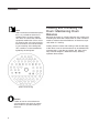
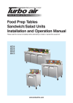
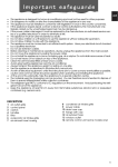
Cel-Gro
Tissue Culture Rotators
Model No.
1640Q
1645Q
056-747-00 • 11/ 05/ 11
Table of Contents
Safety Information ..............................................................................................................................................3
Alert Signals..................................................................................................................................................3
Specifications ......................................................................................................................................................4
Power Requirements ....................................................................................................................................4
Tissue Culture Drum Capacity......................................................................................................................4
Speed of Rotation ........................................................................................................................................4
Angle of Rotation ..........................................................................................................................................4
Dimensions ..................................................................................................................................................4
Shipping Weight............................................................................................................................................4
Unitʼs Environmental Operating Conditions ................................................................................................5
Unpacking and Installation ..................................................................................................................................6
Shipping Carton ............................................................................................................................................6
Location ........................................................................................................................................................6
Electrical Requirements................................................................................................................................6
Operation ............................................................................................................................................................7
Startup and Operation ................................................................................................................................7
Loading and Unloading the Drum: Maintaining Drum Balance ....................................................................8
Maintenance........................................................................................................................................................9
Gearmotor and Shaft Bearing Lubrication ....................................................................................................9
Motor Brush Inspection/Replacement Model 1640Q ..........................................................................................9
Power Switch Replacement........................................................................................................................10
Tightening the Timing Belt Model 1645Q....................................................................................................11
Replacing the Motor....................................................................................................................................11
Troubleshooting ................................................................................................................................................13
Replacement Parts............................................................................................................................................14
Ordering Procedures ........................................................................................................................................15
Two Year Limited Warranty ..............................................................................................................................16
Safety Information
Alert Signals
Warning
Warnings alert you to a possibility of
personal injury.
Caution
Cautions alert you to a possibility of
damage to the equipment.
Note
Notes alert you to pertinent facts and
conditions.
Hot Surface
Hot surfaces alert you to a possibility of
personal injury if you come in contact
with a surface during use or for a period
of time after use.
Warning
This rotator is designed to operate at
a temperature not to exceed 40º.
Operating at temperatures above 40º
will damage the unit and/or result in
injury to personnel.
Model 1640Q
Models 1640Q and 1645Q provide both small and large
laboratories with the versatility to carry out a variety of
rotating and mixing operations. Optimum culture results
are achieved in such applications as tissue and virus
growth, hormone production from selected tissues, sample testing to determine the presence of viruses and cytotoxicity assays.
Model 1640Q rotates a single drum that can be adjusted
from 5º above horizontal to 90º. The variable-speed feature permits a range of motion from a slow, gentle rotation, 12 rpm, to a progression of more vigorous rotating
speeds up to 70 rpm.
Model 1645Q accommodates 1 or 2 drums that can be
rotated at a fixed speed of 0.2 rpm. Drums are not fastened to a motor shaft, but are placed on the parallel,
motor driven, grooved rollers for instant operation.
Available drums: Model #1647 holds 142, 16 mm tubes;
Model #1648 holds 76, 25 mm tubes; and Model #1651
holds 60, 30 mm tubes. Drums must be ordered separately. The drums consist of 3 circular plates (2 are perforated) that are carefully aligned and securely formed into
a rigid assembly of heavy-gauge, anodized aluminum.
The rotators can also fit into and be operated in standard
incubators for cultivation under controlled temperature
conditions. A pilot light indicates when units are operational.
Every unit is finished in a powder coated stainless steel
for easy clean up and maintenance.
Model 1645Q
3
Specifications
Power Requirements:
1640Q: 120 VAC, 60 Hz, 60 W, 0.5 Amps
1645Q: 120 VAC, 60 Hz, 100 W, 0.8 Amps
Tissue Culture Drum Capacity:
1647Q: 142, 16 mm tube capacity
1648Q: 76, 25 mm tube capacity
1651Q: 60, 30 mm tube capacity
Note: Drums are not included, and must be ordered separately.
Speed of Rotation:
Model 1640Q: Adjustable from 12 to 70 rpm
Model 1645Q: Fixed 0.2 rpm
Angle of Rotation:
Model 1640Q: Adjustable 5º above horizontal to 90º
Model 1645Q: Non-adjustable
Dimensions:
Model 1640Q, with drum: 14" W x 22-1/2" H x 15" D (36 x 57x 38 cm)
Model 1645Q: 15-1/2" W x 18" H x 28" D (39 x 46 x 71 cm)
Shipping Weight:
Model 1640Q: 19 lbs. (9 kg)
Model 1645Q: 28 lbs. (13 kg)
4
SPECIFICATIONS
Unitʼs Environmental Operating Conditions
Pollution Degree:
Installation Category:
Altitude:
Humidity:
Electrical Supply:
Voltage Tolerance:
Temperature:
Product Usage:
2
II
2000 meters MSL (Mean Sea Level)
80% maximum, non-condensing
120VAC
±10% of normal rated line
15°C to 40°C
This product is intended for use indoors only
5
Unpacking and Installation
Shipping Carton
The shipping carton should be inspected upon delivery.
When received, carefully examine for any shipping damage before unpacking. If damage is discovered, the delivering carrier should both specify and sign for the damage
on your copy of the delivery receipt.
Open the carton carefully making certain that all parts are
accounted for before packaging materials are discarded.
After unpacking, if damage is found promptly report it to
the carrier and request a damage inspection promptly.
IMPORTANT: Failure to request an inspection of damage
within a few days after receipt of shipment absolves the
carrier from any liability for damage. You must call for a
damage inspection promptly.
Location
Place the rotator on a bench in a convenient location or
inside an incubator.
Note
Leave unit disconnected when not in
use.
6
Electrical Requirements
120 VAC models require a 120 VAC, 50/60 Hz power
source. They are supplied with a 3-wire line cord and
should be plugged into an outlet designed for 3-prong
plugs. If an extension cord is used, it also should be the
3-wire grounded type. For an outlet designed to accept
2-prong plugs (ungrounded), it is required that a qualified
electrician replace the outlet with a new grounded type.
Operation
Warning
Do not use in the presence of flammable or combustible materials or
explosive gases. Do not use in the
presence of pressurized or sealed
containers – fire or explosion may
result, causing death or severe
injury.
Startup and Operation
1.
2.
3.
4.
5.
6.
Make sure that on/off power switch is in the OFF
position. In addition, for Model 1640Q, rotate the
speed control dial all the way to the LEFT or the
completely counterclockwise position. Model
1645Q incorporate a fixed rotation.
When loading test tubes in the rotating drum, space
tubes as evenly as possible throughout the drum
area-this will insure an even rotational speed and
reduce wear on the drive assembly. Make sure
that test tubes are inserted to the back of the drum
and that they are capped so that no spilling of the
contents can occur.
To attach the rotating drum for Model 1640Q, slide
or insert the center hole of the drum onto the stainless steel shaft that extends from the center of
drum mounting unit. Thread the drum-retaining
knob onto the shaft until drum is securely in place.
Model 1645Q requires the drums be placed side by
side on the parallel, grooved rollers.
For Model 1640Q, the angle of rotation can be
adjusted by loosening the bolts on the sides of the
drum-mounting unit. Adjust to the desired angle
and securely retighten the bolts on both sides. For
Model 1645Q, turning the leveling foot on the base
of the unit can change the angle of rotation to a
maximum of approximately 15º from the horizontal.
Turn ON the unit by depressing the on/off power
switch.
For Model 1640Q, it is suggested that the speed of
rotation be adjusted slowly to the desired setting to
insure that drum is secure and rotating properly in a
counter-clockwise rotation, and that test tubes are
securely capped preventing loss of any of their contents.
7
OPERATION
Note
After continued and extended operation, it is possible for the drum to
exhibit uneven or erratic rotation.
This does not necessarily indicate
equipment malfunction and a cause
for returning the unit to the manufacturer. Instead, it can indicate stretching or loosening of the timing belt.
This condition can be remedied by
tightening the timing belt.
Drum, Front Facing
Caution
Failure to load or unload the drum
as listed above may result in uneven
drum rotation or possible stalling of
the drum.
8
Loading and Unloading the
Drum: Maintaining Drum
Balance
Because the rotator is a finely balanced unit, loading and
unloading the drum with culture tubes or other containers
needs to maintain the overall balance of the drum, especially when it is moving.
Starting from the center and working to the outside edge
of the drum, insert or remove tubes that are diametrically
opposed-that is, from the top, bottom, left, right. In this
way container weight is distributed evenly, allowing
optimum drum rotation.
Maintenance
Note
Make no attempt to service or repair
a Thermo Scientific product under
warranty before consulting your
Thermo Scientific dealer. After the
warranty period, such consultation is
still advised, especially when the
repair may be technically sophisticated or difficult. If assistance is needed
beyond what the distributor can provide, please call Customer Service at
800-553-0039. No merchandise
should be returned directly to the factory without obtaining a Return
Materials Authorization (RMA) number from Customer Service.
Warning
Disconnect plug from electrical outlet
before attempting any maintenance or
repair of this unit.
Note
To extend the life of the rotator, keep
the on/off switch in the OFF position
when unit is not in use. Clean the unit
occasionally with a damp cloth or
immediately if an accidental spill of
any kind should occur.
Note
In the event that the unit is operated
for continuous periods of time at elevated temperatures in an incubator,
more frequent lubrication is recommended to keep unit operating at optimum levels.
Note
If the equipment is used in a manner
not specified by the manufacturer, the
protection provided by the equipment
may be impaired.
Gearmotor and Shaft Bearing
Lubrication
1.
2.
3.
4.
Turn OFF power to the unit and disconnect from
outlet.
It is recommended that the gear motor be oiled
every 6 months of use.
Remove 10 Phillips screws that secure one half
of assembly of drum mounting unit. This will
permit access to oil holes on motor. A few drops
of good quality oil will be sufficient.
At the same time, a few drops of oil should be
placed on the main drive shaft bearing.
Motor Brush Inspection/
Replacement Model 1640Q
The recommended procedure to determine when motor
brush replacement is necessary is to conduct periodic
inspections of the brushes. This can be done at the same
time that the motor and drive shaft bearing are lubricated
as described on previous page.
1.
2.
3.
4.
Turn OFF power to the unit and disconnect from
outlet.
Remove Phillips screws that secure one half of
assembly of drum mounting unit. This permits
access to gear motor.
Note that there is a black plastic retaining clip at
one end of motor that is connected to a wire
lead. Carefully slide the clip out and away from
the motor. The spring-loaded brush can then be
removed and inspected. If it measures 1/8"
(0.32 cm) or less, it is time to replace BOTH
brushes.
Exercise care when sliding brush-retaining clip
on and off bracket by aligning the two accurately.
This will avoid breaking either or both of the two
plastic parts.
9
MAINTENANCE
5.
6.
7.
8.
9.
Remove 4 nuts that secure motor and drive
shaft assembly bracket to drum mounting unit.
This permits access to the other brush that is
located on the opposite side of the motor.
Note that there are quick-connect wire leads
attached to brush terminal.
Disconnect lead to one brush terminal at a time,
remove old brush, carefully insert new brush
and reconnect wire to terminal.
Repeat procedure for the other brush.
Reverse procedure to secure motor and drive
shaft assembly bracket to the drum-mounting
unit by replacing and securing 4 nuts.
Reassemble the drum-mounting unit with the
Phillips screws.
Power Switch Replacement
1.
2.
3.
4.
5.
10
Turn OFF power to the unit and disconnect from
outlet.
Turn unit on side and remove 8 screws that hold
the bottom panel.
Disconnect wires to power switch. Remember
the location of the wires.
From inside panel, grasp switch on sides with
fingers and depress the plastic springs that
mount the switch. Maintaining pressure on the
springs, work switch out the panel front.
Insert new switch in from front until it clicks into
place and is flush with panel, connect wires and
reverse the remainder of the procedure.
MAINTENANCE
Tightening the Timing Belt
Model 1645Q
1.
2.
3.
4.
5.
Turn OFF power to the unit and disconnect from
outlet.
Remove Phillips screws that secure one half of
assembly of drum mounting unit. This permits
access to timing belt.
Note 4 screws in slots that secure motor to
panel. Loosen screws and slide gear assembly
until timing belt is tightened. The vertical movement of the belt should be in the range of 1/8"
(0.32 cm) to 1/4" (0.64 cm).
Tighten the motor-mounting screws securely.
Reassemble drum-mounting unit and tighten
screws securely.
Replacing the Motor
1.
2.
3.
4.
5.
Turn OFF power to the unit and unplug power
cord from outlet.
Turn unit on its side and remove 8 screws on
outer edges of the bottom of the unit. Still on
the bottom, remove 2 screws that are next to
vent slots. These secure motor cover.
Return unit to normal position and slide top
housing off to gain access to front housing plate.
Note leads to on/off switch. Disconnect the 3
leads. Remove top housing of unit completely.
Front housing plate of unit is now accessible.
Note 2 screws at either end of housing plateremove. This releases rest of motor cover.
Slide motor cover to back of unit out of the way.
Initially LOOSEN the 4 screws that secure motor
to front housing plate. Slide screws to center of
slots and remove pulley belt. Now remove
screws completely.
11
MAINTENANCE
6.
Note: Wrench may have to be manipulated to gain
access to screw.
7.
Remove set screws and two lead wires on the PCB.
9.
Position the new motor and PCB in place and carefully reverse procedure to install.
8.
12
Use a 5/64" Allen wrench (0.19 cm) to remove
setscrew from timing belt pulley. This pulley is
attached to motor shaft.
Remove motor together with PCB.
Troubleshooting
Note
Before attempting any repair,
disconnect power cord from outlet.
Symptom
Drum not rotating:
The following is intended as a guide to help in servicing
this unit, if problems should occur.
Possible Causes of Problem
Power cord not connected--connect.
Electric power interruption--push in circuit breaker.
Electric short--check wiring/power cord.
Brushes burned out, Model 1640Q--replace.
Drum not responding to speed
control, Model 1640Q:
Drum(s) rotating erratically:
Power switch broken--replace.
Loose timing belt, Model 1645Q--tighten.
Speed control assembly failed--replace.
Drum retaining knob loose, Model 1640Q--tighten.
Drum retaining knob loose, Model 1640Q--tighten.
Pulley(s) loose on shafts--tighten setscrew(s) on pulley(s).
Loose timing belt, Model 1645Q--tighten.
Test tubes loaded unevenly into drum(s)--space tubes
evenly.
13
Replacement Parts
DESCRIPTION
Circuit Breaker, 1.0 Amp:
Cordset, 120 VAC units:
Cordset, CE certified units:
Drum-Retaining Knob, Model 1640Q:
Feet, Rubber (4):
Motor, Model 1640Q:
PCB, Model 1640Q:
Motor, Model 1645Q:
RPO Motor Kit:
Bearing Housing Assy:
Speed Control PCB Assy Model 1640Q:
Switch, 120V:
Timing Belt, Model 1645Q:
Timing Belt, Model 1640Q:
Wiring Schematic, 1640Q:
Wiring Schematic, 1645Q:
Fuse, Model 1640Q:
14
PART NUMBER
330-158-00
470-132-00
470-299-00
560-237-00
790-214-00
370-398-00
PC1662X1
370-328-00
017-948-01
011-483-00
019-086-00
440-359-00
150-259-00
150-258-00
229-097-00
227-846-00
FZX49
Ordering Procedures
Please refer to the Specification Plate for the complete
model number, serial number, and series number when
requesting service, replacement parts or in any correspondence concerning this unit.
All parts listed herein may be ordered from the Thermo
Scientific dealer from whom you purchased this unit or
can be obtained promptly from the factory. When service
or replacement parts are needed we ask that you check
first with your dealer. If the dealer cannot handle your
request, then contact our Customer Service Department
at 563-556-2241 or 800-553-0039.
Prior to returning any materials, please contact our
Customer Service Department for a “Return Materials
Authorization” number (RMA). Material returned without
an RMA number will be refused.
15
North America: USA/Canada +1 866 984 3766 (866-9-THERMO) www.thermo.com
Europe: Austria +43 1 801 40 0, Belgium +32 2 482 30 30, France +33 2 2803 2180, Germany
national toll free 08001-536 376,
Germany international +49 6184 90 6940, Italy +39 02 02 95059 434-254-375, Netherlands +31 76
571 4440, Nordic/Baltic countries +358 9 329 100,
Russia/CIS +7 (812) 703 42 15, Spain/Portugal +34 93 223 09 18, Switzerland +41 44 454 12 12, UK/
Ireland +44 870 609 9203
Asia: China +86 21 6865 4588 or +86 10 8419 3588, India toll free 1800 22 8374, India +91 22 6716
2200, Japan +81 45 453 9220,
Other Asian countries +852 2885 4613 Countries not listed: +49 6184 90 6940 or +33 2 2803 2180