1
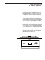
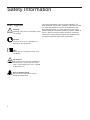
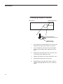
Thermal Rocker®
Model No.
4637Q
4637JPNQ
4637-1CEQ
4637-1CECN
057-089-00 •11/05/11
Table of Contents
Description ..........................................................................................................................................................3
Safety Information ..............................................................................................................................................4
Alert Signals..................................................................................................................................................4
Specifications ......................................................................................................................................................5
Power Requirements ....................................................................................................................................5
Rocking Speed..............................................................................................................................................5
Temperature Range ......................................................................................................................................5
Overall Dimensions ......................................................................................................................................5
Platform ........................................................................................................................................................5
Shipping Weight ............................................................................................................................................5
Declaration of Conformity ............................................................................................................................6
Units Environmental Operating Conditions ..................................................................................................6
Unpacking and Installation ..................................................................................................................................7
Shipping Carton ............................................................................................................................................7
Location ........................................................................................................................................................7
Electrical Requirements................................................................................................................................7
Operation ............................................................................................................................................................9
Temperature Controlled Operations..............................................................................................................9
Auto Tune ....................................................................................................................................................10
For Best Results ..................................................................................................................................10
Auto Tuning Procedure ........................................................................................................................11
Temperature Calibration..............................................................................................................................11
Rocking Motion Only Applications ..............................................................................................................13
General Notes ............................................................................................................................................13
Maintenance......................................................................................................................................................14
Cleaning Spills ............................................................................................................................................14
Parts Replacement ....................................................................................................................................14
3-Position Rocker Switch......................................................................................................................14
Rocker Motor ........................................................................................................................................14
Motor Brushes ......................................................................................................................................15
Temperature Controller ........................................................................................................................15
Changing Angle of Motion....................................................................................................................16
Replacement Parts............................................................................................................................................17
Ordering Procedures ........................................................................................................................................18
Warranty ............................................................................................................................................................19
2
Description
The Thermo Scientific Lab-Line Thermal Rocker provides
the versatility of a variable speed rocking platform in a
temperature-controlled environment. This makes it ideal
for hybridizations, cell culture studies and blood procedures.
Rocking speed can be set from 0 to 100 cycles per
minute and the angle of rotation is adjustable from 10° to
15° from horizontal. Microprocessor-based temperature
controller maintains temperature under the polycarbonate
cover from ambient +5ºC to 70ºC. Automatic resetting
thermal cutoff terminates power to the heaters in the
event temperature set point is exceeded.
The 14-3/16" square (36 cm) platform has a rubber mesh
pad that prevents vessels from slipping and is removable
for easy cleaning. A 1/2" (1.3 cm) ledge on all sides prevents vessels from sliding off. Rubber feet provide stability and keep the unit from creeping during operation.
The enclosed motor and rugged, all-steel, powder coated
body are designed to provide years of virtually maintenance-free service. Convenient, panel mounted, switch
allows operation with or without heat.
3
Safety Information
Your Thermo Scientific Lab-Line Thermal Rocker® has
been designed with function, reliability, and safety in mind.
It is your responsibility to install it in conformance with
local electrical codes. It is most important that the user
Warning
Warnings alert you to a possibility of per- follow installation instructions exactly as written. Failure to
do so is likely to lead to improper operation, erroneous
sonal injury.
calibrations and possible damage to the equipment. Do
not attempt operation without this information.
Alert Signals
Caution
Cautions alert you to a possibility of
damage to the equipment.
Note
Notes alert you to pertinent facts and
conditions.
Hot Surface
Hot surfaces alert you to a possibility of
personal injury if you come in contact
with a surface during use or for a period
of time after use.
Risk of Electric Shock
Disconnect unit from power source
before removing cover.
4
Specifications
Power Requirements
4637Q:
4637JPNQ:
4637-1CEQ & 4637-1CECN:
120 V, 50/60 Hz, 3.3 Amps, 400 Watts
100-120 V, 50/60 Hz, 3.0-3.3 Amps, 400 Watts
220-240 V, 50/60 Hz, 1.7 Amps, 400 Watts
Rocking Speed
0 to 100 cycles per minute
Temperature Range
From ambient +5ºC to 70ºC (with polycarbonate cover in place) as measured by a thermocouple positioned at
approximate geometric center. The temperature in vessels with the polycarbonate cover in place will vary from
these values depending on such factors as vessel size and contents, thickness of the glassware used and
ambient conditions.
Measurements conducted under controlled conditions with 30 cm dna tube filled with 10 ml water, ambient at
23ºc and temperature equalizes at 42ºC.
Overall Dimensions
16" W x 13-1/4" D x 7-3/4" H* (41 x 34 x 20 cm)
Platform
14-3/16" W x 14-3/16 D (36 x 36 cm)
Shipping Weight
25 lb. (11 kg)
*Polycarbonate cover adds 5" (12.7 cm) to rocker's height
5
SPECIFICATIONS
Declaration of Conformity
(For 220 to 240 volt, CE models only)
We hereby declare under our sole responsibility that this product conforms with the technical requirements of
the following standards:
EMC:
EN 61000-3-2
EN 61000-3-3
EN 61326-1
Limits for harmonic current emissions
Limits for voltage fluctuations and flicker
Electrical equipment for measurement, control, and laboratory use;
Part l: General Requirements
Safety: EN 61010-1
Safety requirements for electrical equipment for measurement, control, and
laboratory use; Part I: General Requirements
Part II: Particular requirements for laboratory equipment for the heating of
materials
Part II: Particular requirements for laboratory equipment for mixing and stirring
EN 61010-2-010
EN 61010-2-051
per the provisions of the Electromagnetic Compatibility Directive 2004/108/EC, and per the provisions of the
Low Voltage Directive 2006/95/EC.
The authorized representative located within the European Community is:
Thermo Fisher Scientific
Electrothermal House
Unit 12A
Purdeys Industrial Estate
Purdeys Way
Rochford, Essex, SS4 1ND
United Kingdom
Tel: +44(0)1702 303350
Copies of the Declaration of Conformity are available upon request.
Unit's Environmental Operating Conditions
Pollution Degree:
Installation Category:
Altitude:
Humidity:
Electrical Supply:
Voltage Tolerance:
Temperature:
Product Usage:
*Refer to IEC 664-1
6
2
II
2000 Meters MSL (Mean Sea Level)
80% maximum, non-condensing
120VAC or 240VAC
±10% of normal rated line
15ºC to 40ºC
This product is intended for use indoors only
Unpacking and Installation
Shipping Carton
This should be inspected upon delivery. When received,
carefully examine for any shipping damage before unpacking. If damage is discovered, the delivering carrier should
both specify and sign for the damage on your copy of the
delivery receipt.
Open the carton carefully making certain that all parts are
accounted for before packaging materials are discardedafter unpacking, if damage is found promptly report it to
the carrier and request a damage inspection promptly.
IMPORTANT: Failure to request an inspection of damage
within a few days after receipt of shipment absolves the
carrier from any liability for damage: you must call for a
damage inspection promptly.
Location
Place the unit on a level surface in a convenient location
and near a grounded electrical outlet that matches the
requirements listed on the nameplate. Locate the unit
away from heat sources that might affect the temperature
being maintained by a Thermal Rocker.
Electrical Requirements
Caution
The power cord serves as the main
power disconnect. Access to the
power outlet should be unobstructed
to allow the unit to be unplugged (disconnected) from the power source.
120 VAC models require a 120 VAC, 50/60 Hz power
source. They are supplied with a 3-wire line cord. It should
be plugged into an outlet designed for 3-prong plugs. If an
extension cord is used, it also should be the 3-wire
grounded type. For an outlet designed to accept 2-prong
plugs (ungrounded), it is required that a qualified electrician replace the outlet with a new grounded type.
240 VAC models require a 240 VAC, 50/60 Hz power
source and are supplied with a European cord set.
Note
Leave rotator disconnected when
not in use.
100-120 VAC models require a 100-120 VAC, 50/60 Hz
power source. Because of the variety of plug configurations in use worldwide for 100 to 120 VAC power, the unit
is furnished with the plug removed. The user must install a
plug to conform with local code and configuration requirements.
7
7
UNPACKING
AND INSTALLATION
If a plug must be installed, use only the 3-prong grounded
type, rated for the unit load requirements and matching
the power outlet. Make sure the green ground wire is
secured to the plug ground terminal.
The user shall be made aware that the protection provided by the equipment may be impaired if the equipment is
used with accessories not provided or recommended by
the manufacturer, or used in a manner not specified by
the manufacturer.
8
Operation
Control Panel
1
2
3
1.
ROCKER SWITCH: 3-position switch enables
platform to: rock with heat, rock without heat, or
heat only without motion.
2.
STATUS LAMP: Illuminates when rocker's
heaters are activated.
3.
TEMPERATURE CONTROLLER:
Microprocessor-based controller maintains temperature and provides display of either set point
or actual temperature.
4.
SPEED CONTROL: Adjusts rocking speed.
Markings on dial are for reference purposes
only.
4
Warning
Do not use in the presence of flammable or combustible materials or explosive gases. Do not use in the presence
of pressurized or sealed containersfire or explosion may result, causing
death or severe injury.
Warning
The outer edges and bottom of the
platform can become very hot at elevated temperatures. To avoid burns do
not touch or get too close to the platform when heating at higher temperatures. Allow unit to cool down before
removing vessels or touching unit.
Temperature Controlled
Applications
•
The polycarbonate cover must be in place for
those applications where temperature control
and rocking action are combined.
•
Make certain that the 3-position rocker switch is
in OFF position.
•
Connect power cord to electrical outlet meeting
requirements stated on unit's nameplate.
•
Load platform with vessels to be shaken. Allow
ample space between vessels so that accidental
contact will be avoided.
The user is responsible for determining safe
operation in the use of vessels at various rocking motion speeds and for checking that the vessels are secure while in motion.
•
Turn the rocker switch to the ROCK N HEAT
position to rock and heat simultaneously. Status
light over switch will illuminate indicating power
is supplied to the heaters. Adjust the temperature and speed control dials to desired settings.
9
OPERATION
Actual or Setpoint Temperature
1.
Controller Self-Test: When the rocker is powered
up, the controller will display 8888 along with the
three decimal points and the heat ON indicator
lamp. The display will then blank out for 2 seconds before showing the temperature.
2.
Heat On Indicator: The heat ON indicator lamp
is lit when the rocker's heaters are receiving
power. The lamp will normally flash when the
temperature is at set point.
3.
Set Point Adjustments: The controller normally
displays the temperature. To view or change the
temperature set point proceed as follows:
Heat Indicator
70.0
Control Buttons
✱
▼
▼
Press
.
.M
.L
Controller
View setpoint
Decrease setpoint
Increase setpoint
A.
Press and hold the star key and use either the
up or down arrow key to adjust the set point to
the desired temperature. Release the star key.
B.
Allow at least 30 minutes for the chamber temperature to stabilize.
Auto Tune
The auto tune program automatically adjusts the controller's parameters to achieve optimal temperature control. It is not necessary to run the auto tune program
when setting up the rocker. However, if the temperature
appears to be unstable, the auto tune program can be run
using the procedure shown below:
For Best Results
10
•
Set the usual set point temperature and use normal load conditions.
•
Allow the rocker to stabilize at set point for at
least 30 minutes.
OPERATION
Auto Tuning Procedure
A.
Enter the program mode by pressing and holding
BOTH the up and down arrow keys for 3 seconds.
B.
Release BOTH arrow keys when tunE is displayed.
C.
The controller display should now be alternating
between tunE and oFF.
D.
Press and hold the "STAR" (.) key. Press and
release the up arrow key until At.SP is displayed.
Release the "STAR" (.) key.
E.
After one minute has elapsed, the controller display will begin to alternate between showing the
chamber temperature, tunE and At.SP.
F.
Allow the program to run until the display again
shows only the temperature.
Temperature Calibration
A.
Place a calibrated thermometer near the approximate geometric center of the platform in a position that would allow it to be read through the
glass door.
B.
Press and hold the "STAR" (.) key and using the
up or down arrow key, adjust the set point to the
desired temperature.
C.
Allow the unit to run for at least 30 minutes.
D.
Controller display should now be indicating the
set point temperature. Make note of the thermometer reading.
E.
Press and hold both arrow keys until the controller display indicates tunE. Release the arrow
keys. Press and release the down arrow key, the
11
OPERATION
display should now indicate LEUL. Press and
hold the "STAR" (.) key and using the up arrow
key adjust the display to read 3. Release the
"STAR" (.) key. Press and release the up arrow
key until the display indicates Zero. The display
should now alternate between Zero and a
numerical value.
F.
Using the examples shown below and the thermocouple value obtained in step above, enter
the correct Zero value into the controller by
pressing the "STAR" (.) key and using the up or
down arrow keys. If there is already a Zero
value present then add the new value to the one
already present.
Thermometer
Controller Reading
Subtract
Enter Zero value of
12
= 70 °C
= 75 °C
= -5 °C
-5 °C
Thermometer
Controller Reading
Subtract
Enter Zero value of
= 70 °C
= 65 °C
= +5 °C
+5 °C
G.
When the correct Zero value has been entered,
press and hold the two arrow keys together until
the display again indicates the chamber temperature. If the procedure was done correctly, the
controller display should now agree with the
thermometer reading to within ±0.5ºC.
H.
Allow the unit to run for at least 30 minutes.
I.
Re-check the thermometer reading, the controller display and the thermometer should agree
to within ±0.5ºC. If not repeat steps D, E and F
above.
OPERATION
Rocking Motion Only
Applications
•
Turn the rocker switch to the ROCK position for
rocking action only.
•
Adjust the speed control to the desired rocking
speed.
•
Load platform with vessels to be shaken. Allow
ample space between vessels, so that accidental contact will be avoided.
The user is responsible for determining safe
operation in the use of vessels at various rocking motion speeds and for checking that the vessels are secure while in motion.
General Notes
During rocking action, observe vessels in motion to determine that contents are not escaping or spilling onto the
platform. If this should occur, turn temperature and speed
control dials to 0 and the 3-position rocker switch to the
OFF position. Wait for platform to cool down before
attempting clean up.
In the event of electrical overload, the unit is protected by
resettable, pushbutton circuit breaker on the back. If overload occurs, the breaker will trip. To reset, disconnect
rocker from power source and push button in.
However, if breaker trips repeatedly, unplug the unit and
have the shaker serviced.
It is best to leave unit disconnected from power source
when not in use.
13
Maintenance
Cleaning Spills
Note
Make no attempt to service or repair a
Thermo Scientific product under warranty before consulting your distributor. After the warranty period, such
consultation is still advised, especially
when the repair may be technically
sophisticated or difficult.
If assistance is needed beyond what
the distributor can provide, please call
the customer service department at 1800-553-0039. No merchandise, however should be returned without prior
approval.
Caution
Disconnect plug from electrical outlet
before attempting any maintenance or
repair of this unit.
14
In the event of any spills on the surfaces of the unit, carry
out appropriate neutralization procedures and/or wash off
with a cleaning solution of warm water and a mild detergent. Rinse off with clean water and dry thoroughly. Do
not use abrasive cleaners on surfaces.
Parts Replacement
3-Position Rocker Switch
To access the rocker switch, remove the cover. Turn the
unit over and remove 6 Phillips screws holding the bottom. Remove the 5 wires attached to the switch. Note
attachment sequence and numbers imprinted on switch
terminal. Compress spring release on sides of switch and
withdraw through the front of the panel. Insert the replacement switch. Reconnect wires to the new switch in the
correct locations.
Reverse procedure and reattach the bottom cover.
Rocker Motor
•
To access rocker motor, remove bottom plate.
•
Remove Allen screw from the end of the eccentric. Loosen the 2 set screws holding the eccentric to the motor shaft.
•
Slide the eccentric off the end of the motor
shaft. Remove the 4 screws holding the motor
to bracket.
•
Disconnect wires to the motor.
•
Install new motor and reverse the procedure.
MAINTENANCE
Motor Brushes
•
Under normal conditions of use, the DC motor
brushes should be checked once a year and
replaced if worn.
•
Disconnect plug from outlet. Remove bottom
plate.
•
Unscrew brush cap from side of motor.
•
Remove spring and brush. Replace brushes if
worn to less than 1/4" (0.64 cm) in length. It is
important that BOTH brushes be replaced, even
though only one may be worn.
Temperature Controller
Note
PCB contacts at rear of controller fit
into contacts at rear of controller
housing.
1.
Place ON/OFF switch in OFF position.
2.
Unplug rocker from outlet power supply.
3.
To remove controller from control housing:
•
use both hands to firmly grip each side of
the controller bezel
•
press on the bezel side grips until the bezel
tabs release
•
slowly pull controller from housing
4. To install new, factory configured controller:
•
Carefully slide new controller into controller
housing.
•
Press controller bezel into controller housing
until bezel tabs securely lock controller into
place
5. Plug rocker into outlet power supply.
6. Place ON/OFF switch in ON position.
15
MAINTENANCE
Changing Angle of Motion
Rear Panel
Stroke Adjustment
Access Hole
Stroke Adjustment Arm
3 Stroke Angle
Adjustment Slots
16
1.
Pry off plug from stroke adjustment accesses hole
located on the right side of rocker's rear panel.
2.
Insert screwdriver and remove the stroke adjustment screw that holds stroke adjustment arm in
place.
3.
Reposition stroke adjustment arm over one of the
2 remaining stroke adjustment slots.
4.
Tighten into position with screw removed in step 1.
5.
Snap plug into place over access hole.
6.
Repositioning stroke adjustment allows angle of
rotation to be adjusted from 10° to 15° from horizontal.
Replacement Parts
Description
Circuit Breaker, 1 Amp:
Circuit Breaker, 5 Amp:
Cordset for 4637Q and 4637JPNQ:
Cordset for 4637-1CEQ:
Cordset for 4637-1CECN:
Cover:
Rubber Feet (4):
Heater, 100/120V, 200 Watts:
Speed Control Knob:
Mat, Rubber:
Motor:
RPO Motor Brushes:
Lamp Base, Green:
Lens, Green:
Speed Control, 120V:
Speed Control, 240V:
Switch, Rocker:
Configured Temperature Controller:
RTD Temperature Sensor:
Solid State Relay:
Wiring Schematic, 100/120V Unit:
Wiring Schematic, 240V Unit:
Part Number
330-158-00
330-118-00
470-187-00
CRX77
CRMX10
720-505-00
790-214-00
340-002-00
560-225-00
790-380-00
370-341-00
370-341-01
360-249-01
360-238-00
227-841-00
229-419-00
440-373-00
485-360-12
410-632-00
400-233-00
229-235-00
229-299-00
17
Ordering Procedures
Please refer to the Specification Plate for the complete
model number, serial number, and series number when
requesting service, replacement parts or in any correspondence concerning this unit.
All parts listed herein may be ordered from the Thermo
Scientific dealer from whom you purchased this unit or
can be obtained promptly from the factory. When service
or replacement parts are needed we ask that you check
first with your dealer. If the dealer cannot handle your
request, then contact our Customer Service Department
at 563-556-2241 or 800-553-0039.
Prior to returning any materials, please contact our
Customer Service Department for a “Return Materials
Authorization” number (RMA). Material returned without
an RMA number will be refused.
18
North America: USA/Canada +1 866 984 3766 (866-9-THERMO) www.thermo.com
Europe: Austria +43 1 801 40 0, Belgium +32 2 482 30 30, France +33 2 2803 2180, Germany
national toll free 08001-536 376,
Germany international +49 6184 90 6940, Italy +39 02 02 95059 434-254-375, Netherlands +31 76
571 4440, Nordic/Baltic countries +358 9 329 100,
Russia/CIS +7 (812) 703 42 15, Spain/Portugal +34 93 223 09 18, Switzerland +41 44 454 12 12, UK/
Ireland +44 870 609 9203
Asia: China +86 21 6865 4588 or +86 10 8419 3588, India toll free 1800 22 8374, India +91 22 6716
2200, Japan +81 45 453 9220,
Other Asian countries +852 2885 4613 Countries not listed: +49 6184 90 6940 or +33 2 2803 2180