1
Gearmotors \ Industrial Gear Units \ Drive Electronics \ Drive Automation \ Services
Fieldbus Interface DFE24B
EtherCAT
Edition 05/2007
11571810 / EN
Manual
SEW-EURODRIVE – Driving the world
1 Important Notes...................................................................................................... 6
1.1 Explanation of symbols .................................................................................. 6
1.2 Integral part of the product ............................................................................. 6
1.3 Note on the documentation ............................................................................ 6
1.4 Liability for defects ......................................................................................... 7
1.5 Product names and trademarks ..................................................................... 7
1.6 Waste disposal............................................................................................... 7
2 Safety Notes ........................................................................................................... 8
2.1 Preliminary information .................................................................................. 8
2.2 General safety notes ...................................................................................... 8
2.2.1 General safety notes for bus systems.................................................. 8
2.3 Transportation / putting into storage .............................................................. 8
2.4 Assembly / installation.................................................................................... 9
2.5 Startup / operation ......................................................................................... 9
3 Introduction .......................................................................................................... 10
3.1 Content of this manual ................................................................................. 10
3.2 Additional documentation............................................................................. 10
3.3 Features ....................................................................................................... 10
3.3.1 MOVIDRIVE®, MOVITRAC® B and EtherCAT .................................. 10
3.3.2 Access to all information .................................................................... 11
3.3.3 Cyclic data exchange via EtherCAT ................................................. 11
3.3.4 Acyclic data exchange via EtherCAT ................................................ 11
3.3.5 Configuration of the EtherCAT option card ........................................ 11
3.3.6 Monitoring functions........................................................................... 12
3.3.7 Diagnostics ........................................................................................ 12
3.3.8 Fieldbus monitor ................................................................................ 12
4 Assembly and Installation Notes ........................................................................ 13
4.1 Installing option card DFE24B in MOVIDRIVE® MDX61B ........................... 13
4.1.1 Before you begin................................................................................ 13
4.1.2 Basic procedure for installing and removing an option card .............. 14
4.2 Installing option card DFE24B in MOVITRAC® B ........................................ 15
4.2.1 SBus connection ................................................................................ 15
4.2.2 System bus connection...................................................................... 16
4.3 Installing the UOH11B gateway housing...................................................... 18
4.4 Connection and terminal description of the DFE24B option ........................ 19
4.5 Pin assignment ............................................................................................ 20
4.6 Shielding and routing bus cables ................................................................. 21
4.7 Bus termination ............................................................................................ 21
4.8 Setting the station address .......................................................................... 21
4.9 Operating displays of the DFE24B option .................................................... 22
4.9.1 EtherCAT LEDs ................................................................................. 22
4.9.2 Gateway LED..................................................................................... 24
Manual – Fieldbus Interface DFE24B EtherCAT
3
5 Configuration and Startup................................................................................... 25
5.1 Validity of the XML files for DFE24B ............................................................ 25
5.2 Configuring the EtherCAT master for MOVIDRIVE® B with the XML file..... 25
5.2.1 XML for operation in MOVIDRIVE® B................................................ 25
5.2.2 Configuration procedure .................................................................... 26
5.2.3 PDO configuration for operation in MOVIDRIVE® ............................. 27
5.3 Configuring the EtherCAT master for MOVITRAC® B / gateway
with XML file................................................................................................. 35
5.3.1 XML files for operation in MOVITRAC® B and
gateway housing UOH11B ................................................................ 35
5.3.2 Configuration procedure .................................................................... 35
5.3.3 PDO configuration for DFE24B gateway for MOVITRAC® B............. 36
5.3.4 Auto setup for gateway operation ...................................................... 41
5.4 Setting the MOVIDRIVE® MDX61B drive inverter ....................................... 42
5.5 Setting the MOVITRAC® frequency inverter ................................................ 43
6 EtherCAT Operating Characteristics.................................................................. 45
6.1 Controlling the MOVIDRIVE® MDX61B drive inverter ................................. 45
6.1.1 Control example in TwinCAT with MOVIDRIVE® MDX61B ............... 46
6.1.2 EtherCAT timeout (MOVIDRIVE® MDX61B) ..................................... 48
6.1.3 Fieldbus timeout response (MOVIDRIVE® MDX61B)........................ 48
6.2 Controlling the MOVITRAC® B (Gateway) frequency inverter ..................... 49
6.2.1 Control example in TwinCAT with MOVITRAC® B (gateway) ........... 50
6.2.2 SBus timeout ..................................................................................... 51
6.2.3 Unit faults ........................................................................................... 51
6.2.4 DFE24B fieldbus timeout in gateway operation ................................. 52
6.3 Configuration via EtherCAT ........................................................................ 52
6.3.1 SDO READ and WRITE services ...................................................... 52
6.3.2 Example of reading a parameter in TwinCAT via EtherCAT.............. 53
6.3.3 Example of writing a parameter in TwinCAT via EtherCAT ............... 55
6.4 Configuration return codes........................................................................... 56
6.4.1 Elements ............................................................................................ 56
6.4.2 Error class.......................................................................................... 56
6.4.3 Error code .......................................................................................... 56
6.4.4 Additional code .................................................................................. 57
6.4.5 List of the error codes for SDO services ............................................ 57
7 Motion Control via EtherCAT ............................................................................. 58
7.1 Introduction to EtherCAT ............................................................................. 58
7.1.1 Velocity mode .................................................................................... 61
7.1.2 Position mode .................................................................................... 62
7.2 Settings in MOVIDRIVE® B with MOVITOOLS® MotionStudio.................... 63
7.2.1 Settings for velocity mode.................................................................. 63
7.2.2 Settings for position mode ................................................................. 65
7.3 Settings in EtherCAT master........................................................................ 67
7.3.1 Settings for velocity mode.................................................................. 67
7.3.2 Settings for position mode ................................................................. 68
7.4 Example in TwinCAT.................................................................................... 69
7.4.1 Velocity mode .................................................................................... 71
4
Manual – Fieldbus Interface DFE24B EtherCAT
8 Operating MOVITOOLS® MotionStudio via EtherCAT ...................................... 74
8.1 Introduction .................................................................................................. 74
8.2 Required hardware ...................................................................................... 75
8.3 Required software ........................................................................................ 75
8.4 Installation .................................................................................................... 75
8.5 Configuring the mailbox gateway ................................................................. 76
8.6 Network settings on the engineering PC...................................................... 76
8.7 Configuring the SEW communication server ............................................... 78
8.7.1 Establishing communication .............................................................. 78
8.7.2 Procedure .......................................................................................... 78
8.8 Automatic search for connected units (unit scan) ........................................ 80
8.9 Activating online mode ................................................................................. 81
8.10 Familiar problems during the operation of MOVITOOLS® MotionStudio ..... 81
9 Error Diagnostics ................................................................................................. 82
9.1 Diagnostic procedures ................................................................................. 82
9.2 List of errors ................................................................................................. 85
10 Technical Data ...................................................................................................... 86
10.1 Option DFE24B for MOVIDRIVE® MDX61B ................................................ 86
10.2 Option DFE24B for MOVITRAC® B and
Universal Gateway Housing UOH11B ......................................................... 87
11 Index ...................................................................................................................... 88
Manual – Fieldbus Interface DFE24B EtherCAT
5
Important Notes
Explanation of symbols
1
1
Important Notes
1.1
Explanation of symbols
Manual
Always observe the safety and warning information in this documentation.
Electrical hazard
Possible consequences: Severe or fatal injuries.
Hazard.
Possible consequences: Severe or fatal injuries.
Hazardous situation.
Possible consequences: Slight or minor injuries.
Harmful situation.
Possible consequences: Damage to the unit and the
environment.
Tips and useful information.
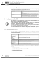
1.2
Integral part of the product
This manual is an integral part of the DFE24B EtherCAT fieldbus interface and contains
important notes on operation and service.
1.3
Note on the documentation
•
You must adhere to the documentation to ensure:
– Fault-free operation
– Fulfillment of any rights to claim under limited warranty
6
•
Therefore, make sure you read this manual carefully before you install and startup
frequency inverters with the DFE24B EtherCAT option card.
•
This manual assumes that the user has access to and is familiar with the
MOVIDRIVE® and MOVITRAC® documentation, in particular the MOVIDRIVE®
MDX60B/61B and MOVITRAC® B system manuals.
Manual – Fieldbus Interface DFE24B EtherCAT
Important Notes
Liability for defects
1.4
1
Liability for defects
Incorrect handling or any action performed that is not specified in this manual could
impair the properties of the product. In this case, you lose any right to claim under limited
warranty against SEW-EURODRIVE GmbH & Co KG.
1.5
Product names and trademarks
The brands and product names in this manual are trademarks or registered trademarks
of the titleholders.
1.6
Waste disposal
Please follow the current national regulations.
Dispose of the following materials separately in accordance with the country-specific
regulations in force:
•
Electronics scrap
•
Plastics
•
Sheet metal
•
Copper
etc.
Manual – Fieldbus Interface DFE24B EtherCAT
7
Safety Notes
Preliminary information
2
2
Safety Notes
Only install and startup the DFE24B EtherCAT fieldbus interface in accordance
with the relevant accident prevention regulations and the MOVIDRIVE®
MDX60B/61B and MOVITRAC® B operating instructions.
2.1
Preliminary information
The following safety notes refer to the use of the DFE24B EtherCAT fieldbus
interface.
Please also observe the supplementary safety notes in the individual sections of
this manual.
2.2
General safety notes
Never install damaged products or take them into operation.
Submit a complaint to the shipping company immediately in the event of damage.
2.2.1
General safety notes for bus systems
This communication system allows you to adjust the MOVIDRIVE® drive inverter to your
specific application very accurately. As with all bus systems, there is a danger of
invisible, external (as far as the inverter is concerned) modifications to the parameters which give rise to changes in the inverter behavior. This may result in unexpected (not uncontrolled) system behavior.
2.3
Transportation / putting into storage
Inspect the shipment for any damage that may have occurred in transit as soon
as you receive the delivery. Inform the shipping company immediately. Do not
operate the product if it is damaged.
Use suitable, sufficiently rated handling equipment if necessary.
Possible damage caused by incorrect storage!
Store the unit in a dry, dust-free room if it is not to be installed straight away.
8
Manual – Fieldbus Interface DFE24B EtherCAT
Safety Notes
Assembly / installation
2.4
2
Assembly / installation
Follow the instructions in section 4, "Assembly and Installation Notes."
2.5
Startup / operation
Follow the instructions in section 5, "Configuration and Startup."
Manual – Fieldbus Interface DFE24B EtherCAT
9
Introduction
Content of this manual
3
3
Introduction
3.1
Content of this manual
This user manual describes how to:
3.2
•
install the DFE24B EtherCAT option card in the MOVIDRIVE® MDX61B drive
inverter
•
use the DFE24B EtherCAT option card in the MOVITRAC® B frequency inverter and
in the UOH11B gateway housing
•
startup MOVIDRIVE® MDX61B on the EtherCAT fieldbus system
•
startup MOVITRAC® B on the EtherCAT gateway
•
configure the EtherCAT master using XML files
•
operate MOVITOOLS® MotionStudio via EtherCAT.
Additional documentation
For information on how to connect MOVIDRIVE® simply and effectively to the EtherCAT
fieldbus system, in addition to this user manual on the EtherCAT option, you should
request the following documentation on fieldbus technology:
•
"MOVIDRIVE® Fieldbus Unit Profile" manual
•
MOVITRAC® B system manual
The "MOVIDRIVE® Fieldbus Unit Profile" manual and the MOVITRAC® B system
manual describe the fieldbus parameters and their coding, and explains the whole range
of control concepts and application options in the form of brief examples.
The "MOVIDRIVE® Fieldbus Unit Profile" manual contains a list of all drive inverter
parameters that can be read or written via the various communication interfaces, such
as system bus, RS485 and also via the fieldbus interface.
3.3
Features
The MOVIDRIVE® MDX61B drive inverter and the MOVITRAC® B frequency inverter
enable you to use the DFE24B option to connect to higher-level automation systems via
EtherCAT using its powerful, universal fieldbus interface.
3.3.1
MOVIDRIVE®, MOVITRAC® B and EtherCAT
The unit behavior of the inverter that forms the basis of EtherCAT operation is referred
to as the unit profile. It is independent of any particular fieldbus and is therefore a
uniform feature. This feature allows the user to develop drive applications independent
of the fieldbus in operation. This makes it much easier to change to other bus systems,
such as DeviceNet (option DFD).
10
Manual – Fieldbus Interface DFE24B EtherCAT
Introduction
Features
3.3.2
3
Access to all information
MOVIDRIVE® MDX61B offers digital access to all drive parameters and functions via
the EtherCAT interface. The drive inverter is controlled via fast, cyclic process data. You
can use this process data channel to enter setpoints (e.g. setpoint speed, ramp generator time for acceleration/deceleration, etc.) and to trigger various drive functions such
as enable, controller inhibit, normal stop, rapid stop, etc. At the same time you can use
this channel to read back actual values from the drive inverter, such as the actual speed,
current, unit status, fault number and reference signals.
3.3.3
Cyclic data exchange via EtherCAT
Process data is usually exchanged cyclically between the EtherCAT master and the
MOVIDRIVE® B and MOVITRAC® B inverters. The cycle time is specified during the
configuration of the EtherCAT master.
3.3.4
Acyclic data exchange via EtherCAT
The EtherCAT specification defines acyclical READ/WRITE services that are transferred together with the telegrams during ongoing cyclical bus operation without impacting on the performance of the process data communication via EtherCAT.
Read and write access to the drive parameters is enabled via SDO (Service Data
Object) services that are implemented according to CoE (CANopen over EtherCAT) or
VoE (Vendor-specific over EtherCAT) services.
This parameter data exchange enables you to implement applications in which all the
important drive parameters are stored in the higher-level programmable controller, so
that there is no need to make parameter settings manually on the drive inverter itself.
3.3.5
Configuration of the EtherCAT option card
The EtherCAT option card is designed so that all fieldbus-specific settings are made
during startup of the EtherCAT system. This process enables the drive inverter to be
integrated and operated in the EtherCAT environment within a very short period of time.
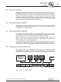
EtherCAT
Master
Ethernet
Header
Frame
Header
SEW
Drive
EtherCAT Data
Header
SEW
Drive
Drive 1
Drive 2
SEW
Drive
Drive 3
I/O
...
FCS
EtherCAT
Figure 1: EtherCAT with MOVIDRIVE®
Manual – Fieldbus Interface DFE24B EtherCAT
61211AXX
11
Introduction
Features
3
3.3.6
Monitoring functions
Using a fieldbus system requires additional monitoring functions for the drive
technology, for example, cycle time monitoring of the fieldbus (fieldbus timeout) or rapid
stop concepts. You can, for example, adapt the monitoring functions of MOVIDRIVE® B
/ MOVITRAC® B specifically to your application. You can determine, for instance, which
of the drive inverter’s fault responses should be triggered in the event of a bus error. It
is a good idea to use a rapid stop function for many applications. However you can also
freeze the last setpoints so that the drive continues to operate with the most recently
valid setpoints (for example, conveyor belt). As the functions of the control terminals are
still active in fieldbus operation, you can still implement fieldbus-independent
emergency stop concepts via the drive inverter terminals.
3.3.7
Diagnostics
The MOVIDRIVE® B drive inverter and MOVITRAC® B frequency inverter both offer a
number of diagnostic options for startup and service. For example, you can use the
integrated fieldbus monitor to control setpoint values sent from the higher-level
controller and the actual values.
3.3.8
Fieldbus monitor
Furthermore, you are supplied with a variety of additional information about the status
of the fieldbus option card. In conjunction with the MOVITOOLS® MotionStudio PC software, the fieldbus monitor function offers you an easy-to-use diagnostic tool for setting
all drive parameters (including the fieldbus parameters) and for displaying the fieldbus
and device status information in detail.
12
Manual – Fieldbus Interface DFE24B EtherCAT
Assembly and Installation Notes
Installing option card DFE24B in MOVIDRIVE® MDX61B
4
4
Assembly and Installation Notes
This section provides you with information on assembly and installation for the DFE24B
option card in MOVIDRIVE® MDX61B, MOVITRAC® B and the UOH11B gateway
housing.
4.1
Installing option card DFE24B in MOVIDRIVE® MDX61B
Only SEW-EURODRIVE personnel may install or remove option cards for
MOVIDRIVE® MDX61B size 0.
4.1.1
•
Users may only install and remove options cards for MOVIDRIVE® MDX61B sizes 1
to 6.
•
The DFE24B option is powered with voltage via MOVIDRIVE® B. A separate voltage
supply is not required.
Before you begin
The DFE24B option card must be installed in the fieldbus slot.
Read the following notes before installing or removing the option card:
•
Disconnect the inverter from the power. Switch off the DC 24 V and the supply
voltage.
•
Take appropriate measures (discharge strap, conductive shoes, etc.) to protect the
option card from electrostatic charge before touching it.
•
Before installing the option card, remove the keypad and the front cover (→
MOVIDRIVE® MDX60B/61B operating instructions, Sec. "Installation").
•
After installing the option card, replace the front cover and the keypad (→
MOVIDRIVE® MDX60B/61B operating instructions, Sec. "Installation").
•
Keep the option card in its original packaging until immediately before you are ready
to install it.
•
Hold the option card by its edges only. Do not touch any subassemblies.
Manual – Fieldbus Interface DFE24B EtherCAT
13
Assembly and Installation Notes
Installing option card DFE24B in MOVIDRIVE® MDX61B
4
4.1.2
Basic procedure for installing and removing an option card
2.
1.
2.
1.
3.
3.
3.
4.
4.
60039AXX
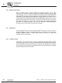
Figure 2: Installing an option card in MOVIDRIVE® MDX61B sizes 1 to 6
1. Remove the two retaining screws holding the card retaining bracket. Pull the card
retaining bracket out evenly from the slot (do not twist!).
2. Remove the 2 retaining screws from the black cover plate on the card retaining
bracket. Remove the black cover plate.
3. Position the option card onto the retaining bracket so that the 3 retaining screws fit
into the corresponding holes on the card retaining bracket.
4. Insert the retaining bracket with the installed option card into the slot, pressing
slightly so it is seated properly. Secure the card retaining bracket with the two retaining screws.
5. To remove the option card, follow the instructions in reverse order.
14
Manual – Fieldbus Interface DFE24B EtherCAT
Assembly and Installation Notes
Installing option card DFE24B in MOVITRAC® B
4.2
4.2.1
4
Installing option card DFE24B in MOVITRAC® B
•
MOVITRAC® B does not require any special firmware status.
•
Only SEW-EURODRIVE personnel may install or remove options cards into
MOVITRAC® B.
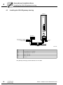
SBus connection
MOVITRAC® B
DFE 24B
S1
[1]
S2
RUN
ERR
ON
OFF
[2]
X44
FSC11B
X45
X46
0
1
AS
F1
HL ⊥ 1 2 3 4 5 6 7
X31
OUT
X30
IN
EtherCAT
H1
H2
X24
X12
+
DC 24 V =
–
24V IO
GND
X26
1
2
3
4
5
6
7
8
9
12 3 45 6 7
61212AXX
[1]
Terminating resistor activated, S1 = ON
[2]
DIP switch S2 (reserved), S2 = OFF
•
DFE24B has an integrated SBus terminating resistor and must always be installed at
the start of the SBus line.
•
DFE24B always has the address 0.
X46
X26
X46:1
X26:1
SC11 SBus +, CAN high
X46:2
X26:2
SC12 SBus –, CAN low
X46:3
X26:3
GND, CAN GND
X46:7
X26:7
DC 24 V
X12
X12:8
DC 24 V input
X12:9
GND reference potential for binary inputs
Manual – Fieldbus Interface DFE24B EtherCAT
15
Assembly and Installation Notes
Installing option card DFE24B in MOVITRAC® B
4
For simple cabling, the DFE24B option can be provided with DC 24 V voltage at X26.7
from X46.7 of MOVITRAC® B.
When powering option DFE24B through MOVITRAC® B, MOVITRAC® B itself must be
provided with DC 24 V voltage at terminals X12.8 and X12.9.
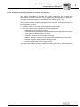
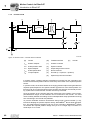
4.2.2
System bus connection
MOVITRAC® B
DFE 24B
S1
S2
RUN
ERR
ON
OFF
X44
FSC11B
X45
X46
0
1
AS
F1
HL⊥1 2 3 4 5 6 7
X31
OUT
X30
IN
EtherCAT
H1
H2
MOVITRAC® B
MOVITRAC® B
X24
S1
X12
+
DC 24 V =
-
24V IO
GND
1
2
3
4
5
6
7
8
9
S2
X26
ON
12 3 45 6 7
OFF
X44
X46
HL ⊥ 1 2 3 4 5 6 7
16
ON
OFF
FSC11B
X45
X46
HL ⊥ 1 2 3 4 5 6 7
61073AXX
Figure 3: System bus connection
DFE24B
GND = System bus reference
SC11 = System bus high
SC12 = System bus low
S2
X44
FSC11B
X45
S1
MOVITRAC® B
GND
= System bus reference
SC22 = System bus low, outgoing
SC21 = System bus high, outgoing
SC12 = System bus low, incoming
SC11 = System bus high, incoming
S12
= System bus terminating resistor
Manual – Fieldbus Interface DFE24B EtherCAT
Assembly and Installation Notes
Installing option card DFE24B in MOVITRAC® B
4
Please note:
•
If available, use a 2 x 2 core twisted and shielded copper cable (data transmission
cable with braided copper shield). Apply the shield at both ends to the electronics
shield clamp of MOVITRAC® B over a large area. When using a 2-core cable connect
the shield ends additionally to GND. The cable must meet the following specifications:
– Core cross section 0.25 ... 0.75 mm2 (AWG23 ... AWG18)
– Line resistance 120 Ω at 1 MHz
– Capacitance per unit length ≤ 40 pF/m at 1 kHz
Suitable would be CAN bus or DeviceNet cable.
•
The permitted total cable length depends on the baud rate setting of the SBus:
– 250 kBaud: 160 m
– 500 kBaud: 80 m
– 1000 kBaud:40 m
•
Connect the system bus terminating resistor (S1 = ON) at the end of the system bus
connection. Switch off the terminating resistor on the other units (S1 = OFF). The
DFE24B gateway has a permanently installed terminating resistor and must always
be located at the beginning or end of the system bus line.
•
Star like bus structure is not permitted.
•
There must not be any potential displacement between the units connected with the
SBus. Take suitable measures to avoid potential displacement, e.g. by connecting
the unit ground connectors using a separate lead.
Manual – Fieldbus Interface DFE24B EtherCAT
17
Assembly and Installation Notes
Installing the UOH11B gateway housing
4
4.3
Installing the UOH11B gateway housing
UOH11B
DFE 24B
RUN
ERR
0
1
AS
F1
X31
OUT
X30
IN
EtherCAT
H1
H2
X24
SEW Drive
X26
1234567
SC11 Systembus +, CAN high
SC12 Systembus -, CAN low
GND, CAN GND
DC+24 V
GND
61074AXX
X26
X26:1
SC11 System bus +, CAN high
X26:2
SC12 System bus -, CAN low
X26:3
GND, CAN GND
X26:6
GND, CAN GND
X26:7
DC 24 V
The gateway housing is powered with DC 24 V at X26.
18
Manual – Fieldbus Interface DFE24B EtherCAT
Assembly and Installation Notes
Connection and terminal description of the DFE24B option
4.4
4
Connection and terminal description of the DFE24B option
Part number
EtherCAT interface type DFE24B: 1821 126 7
The option "EtherCAT interface type DFE24B" is only possible in conjunction with
MOVIDRIVE® MDX61B, not with MDX60B.
Plug the DFE24B option into the fieldbus slot.
Front view of DFE24B
DFE 24B
RUN
ERR
0
Description
Function
RUN: EtherCAT operation LED
(orange/green)
Shows the operating status of bus electronics and
communication.
ERR: EtherCAT error LED (red)
Displays EtherCAT errors.
DIP switch
1
DIP
switches
Terminal
AS
F1
AS
F1
Auto setup for gateway operation
Reserved
EtherCAT
IN
LED Link/Activity (green)
Shows that the EtherCAT connection with the preceding unit is available/active.
X30
X30 IN: Incoming EtherCAT
connection
OUT
LED Link/Activity (green)
Shows that the EtherCAT connection with the following unit is available/active.
X31
X31 OUT: Outgoing EtherCAT
connection
58083AXX
Front view in
MOVITRAC® B and
UOH11B
Description
Function
H1
LED H1 (red)
System error (only for gateway functionality)
H2
LED H2 (green)
Reserved
X24
X24 X terminal
RS485 interface for diagnostics via PC and
MOVITOOLS® MotionStudio
58129AXX
Manual – Fieldbus Interface DFE24B EtherCAT
19
Assembly and Installation Notes
Pin assignment
4
4.5
Pin assignment
Use prefabricated, shielded RJ45 plug connectors to IEC11801 edition 2.0, category 5.
[6]
[3] [2] [1]
12
3
A
6
B
Figure 4: Pin assignment of an RJ45 plug connector
54174AXX
A = Front view
B = View from back
[1] Pin 1 TX+ Transmit Plus
[2] Pin 2 TX– Transmit Minus
[3] Pin 3 RX+ Receive Plus
[6] Pin 6 RX– Receive Minus
DFE24B EtherCAT
connection
Option DFE24B is equipped with two RJ45 connectors for a linear bus structure. The
EtherCAT master is connected (if necessary, via additional EtherCAT slaves) to X30 IN
(RJ45) with a shielded, twisted-pair cable. Additional EtherCAT units are then
connected via X31 OUT (RJ45).
In accordance with IEC 802.3, the maximum permitted cable length for 100 MBaud
Ethernet (100BaseT), e.g. between two DFE24B units, is 100 m.
20
Manual – Fieldbus Interface DFE24B EtherCAT
Assembly and Installation Notes
Shielding and routing bus cables
4.6
4
Shielding and routing bus cables
Only use shielded cables and connection elements that also meet the requirements of
category 5, class D according to IEC 11801 edition 2.0.
Correct shielding of the bus cable attenuates electrical interference that can occur in
industrial environments. The following measures ensure the best possible shielding:
•
Manually tighten the mounting screws on the connectors, modules, and equipotential
bonding conductors.
•
Use only connectors with a metal housing or a metallized housing.
•
Connect the shielding in the connector over a wide surface area.
•
Apply the shielding of the bus line on both ends.
•
Route signal and bus cables in separate cable ducts. Do not route them parallel to
power cables (motor leads).
•
Use metallic, grounded cable racks in industrial environments.
•
Route the signal cable and the corresponding equipotential bonding close to each
other using the shortest possible route.
•
Avoid using plug connectors to extend bus cables.
•
Route the bus cables closely along existing grounding surfaces.
In case of fluctuations in the ground potential, a compensating current may flow via the
bilaterally connected shield that is also connected to the protective earth (PE). Make
sure you supply adequate equipotential bonding according in accordance with relevant
VDE regulations in such a case.
4.7
Bus termination
Bus termination (e.g. with bus terminating resistors) is not necessary. If no further device
is connected to an EtherCAT slave, it recognizes this automatically.
4.8
Setting the station address
EtherCAT devices from SEW-EURODRIVE do not have an address that can be set on
the unit. The units are detected by their position in the bus structure and are assigned
an address by the EtherCAT master. The addresses can be displayed, for example,
using the DBG60B keypad (parameter P093).
Manual – Fieldbus Interface DFE24B EtherCAT
21
Assembly and Installation Notes
Operating displays of the DFE24B option
4
4.9
Operating displays of the DFE24B option
4.9.1
EtherCAT LEDs
There are two LEDs on the DFE24B EtherCAT option card that display the current status
of the DFE24B option and the EtherCAT system.
DFE24B
RUN
ERR
61070AXX
LED RUN
(green/orange)
The RUN LED (green/orange) signals the status of option DFE24B.
Status
State
Description
Off
INIT
Option DFE24B is in the state INIT.
Flashing
green
PRE-OPERATIONAL
Option DFE24B is in the state PRE-OPERATIONAL.
Lights up
once (green)
SAFE-OPERATIONAL
Option DFE24B is in the state SAFE-OPERATIONAL.
Green
OPERATIONAL
Option DFE24B is in the state OPERATIONAL.
Flickering
green
INITIALISATION or
BOOTSTRAP
•
•
Flashing
orange
LED ERR (red)
22
NOT CONNECTED
Option DFE24B is booting and has not yet reached the state
INIT.
Option DFE24B is in the state BOOTSTRAP. The firmware
is being downloaded.
Option DFE24B has been switched on but has not yet been
addressed by an EtherCAT master.
The ERR LED (red) signals an error on EtherCAT.
Status
Error
Description
Off
No error
EtherCAT communication of the DFE24B option is in the
operating state.
Flickering
Boot error
A boot error has been detected. The state INIT was achieved,
but the "Change" parameter in the AL status register has been
set to "0x01:change/error".
Flashing
Invalid configuration
General configuration error.
Lights up
once
Unrequested change
in status
The slave application has changed the EtherCAT state automatically. The "Change" parameter in the AL status register has
been set to "0x01:change/error".
Lights up
twice
Application watchdog
timeout
A watchdog timeout occurred in the application.
Lights up
three times
Reserved
-
Lights up
four times
Reserved
-
On
PDI watchdog timeout
A PDI watchdog timeout occurs.
Manual – Fieldbus Interface DFE24B EtherCAT
Assembly and Installation Notes
Operating displays of the DFE24B option
4
Definition of the display statuses
Display
Definition
On
Display is always switched on.
Off
Display is always switched off.
Flickering
Display switches on and off at a
frequency of 10 Hz.
Time profile
50ms
on
off
50ms
58094AXX
Lights up briefly
once
The display lights up briefly, followed
by on off phase.
50ms
on
off
58095AXX
Flashing
Display switches on and off at a
frequency of 2.5 Hz (200 ms on,
200 ms off).
on
200ms
200ms
off
58096AXX
Lights up once
The display lights up once (200 ms),
followed by a longer off phase
(1000 ms).
on
200ms
1s
off
58097AXX
Lights up twice
The display lights up twice in succession, followed by on off phase.
on
200ms
200ms
200ms
1s
off
58100AXX
Lights up three
times
The display lights up three times in
succession, followed by on off phase.
on
200ms
200ms
200ms
200ms
200ms
1s
off
58101AXX
Lights up four
times
The display lights up four times in
succession, followed by on off phase.
on
200ms
200ms
200ms
200ms
200ms
200ms
200ms
1s
off
58102AXX
Manual – Fieldbus Interface DFE24B EtherCAT
23
Assembly and Installation Notes
Operating displays of the DFE24B option
4
Each EtherCAT connection has a "Link/Activity" LED for the incoming EtherCAT cable
(X30) and the outgoing EtherCAT cable (X31). They signal whether the EtherCAT
connection to the preceding (X30) or following (X31) unit is available / active.
IN
LED Link/Activity
(green)
X31
OUT
X30
LED"Link/Activity"
61195AXX
4.9.2
Gateway LED
LEDs for the
gateway communication status
H1
H2
X24
58129axx
LED H1 Sys-Fault (red)
Only for gateway function
Status
State
Description
Red
System error
Gateway not configured or one of the drives
is inactive
Off
SBus ok
Gateway is configured correctly
Flashes
Bus scan
Bus is being checked by the gateway
LED H2 (green) is reserved at present.
X terminal X24 is the RS485 interface for diagnostics via PC and MOVITOOLS® MotionStudio.
24
Manual – Fieldbus Interface DFE24B EtherCAT
Configuration and Startup
Validity of the XML files for DFE24B
I
5
0
5
Configuration and Startup
This section provides you with information on configuration for the EtherCAT master and
startup of the drive inverter for fieldbus operation.
The current version of the XML file for the DFE24B control card is available on the SEW
homepage (http://sew-eurodrive.de) under the heading "Software."
5.1
Validity of the XML files for DFE24B
The XML file is needed when DFE24B is used as a fieldbus option in MOVIDRIVE® B
and as a gateway in MOVITRAC® B or a gateway housing (UOH11B).
Do not change or expand the entries in the XML file. SEW assumes no liability for
inverter malfunctions caused by a modified XML file!
5.2
Configuring the EtherCAT master for MOVIDRIVE® B with the XML file
5.2.1
XML for operation in MOVIDRIVE® B
An XML file (SEW_DFE24B.XML) is available for configuring the EtherCAT master.
Copy this file to a folder in the configuration software.
Refer to the manuals for the appropriate configuration software for details on this
procedure.
The XML files standardized by the EtherCAT Technology Group (ETG) can be read by
all EtherCAT masters.
Manual – Fieldbus Interface DFE24B EtherCAT
25
I
5
Configuration and Startup
Configuring the EtherCAT master for MOVIDRIVE® B with the XML file
0
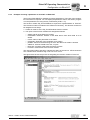
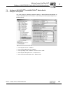
5.2.2
Configuration procedure
Proceed as follows to configure MOVIDRIVE® B with EtherCAT fieldbus interface:
1. Install (copy) the XML file according to the specifications of your configuration software. Once the file has been installed correctly, the device appears next to the slave
stations (under SEW EURODRIVE → Drives) with the designation
MOVIDRIVE+DFE24B.
2. Use the [Insert] menu item to add the device to the EtherCAT structure. The address
is assigned automatically. You can give the device a name to make it easier to
identify.
3. Select the process data configuration required for your application (see section
5.2.3).
4. Connect the I/O or periphery data to the input and output data of the application
program.
Once configuration is complete, you can start EtherCAT communication. The LEDs
RUN and ERR indicate the communication status of option DFE24B (see section 4.9
"Operating displays of the DFE24B option").
26
Manual – Fieldbus Interface DFE24B EtherCAT
Configuration and Startup
Configuring the EtherCAT master for MOVIDRIVE® B with the XML file
I
5
0
5.2.3
PDO configuration for operation in MOVIDRIVE®
In the CoE (CANopen over EtherCAT) variant, EtherCAT uses the process data objects
(PDO) defined in the CANopen standard for cyclical communication between master
and slave. CANopen Standard distinguishes between the process data objects Rx
(Receive) and Tx (Transmit).
Rx process data
objects
Rx process data objects (Rx-PDO) are received by the EtherCAT slave. They transfer
process output data (control values, setpoints, digital output signals) from the EtherCAT
master to the EtherCAT slave.
Tx process data
objects
Tx process data objects (TX-PDO) are returned from the EtherCAT slave to the
EtherCAT master. They transfer process input data (actual values, status, digital input
information, etc.).
In the DFE24B operating mode of MOVIDRIVE® B, two different PDO types can be used
for cyclical process input and output data.
•
OutputData1 (Standard 10 PO)
Static PDO with 10 cyclical process output data words that are connected in fixed
configuration with the standard process data of MOVIDRIVE® B (→ "MOVIDRIVE®
Fieldbus Unit Profile" manual).
•
OutputData2 (Configurable PO)
Configurable PDO with up to 10 cyclical process output data words (16 Bit) and up
to 8 cyclical system variables (32 Bit) that can be configured as required and
connected to various process data of the drive inverter.
•
InputData1 (Standard 10 PI)
Static PDO with 10 cyclical process input data words that are connected in fixed
configuration with the standard process data of MOVIDRIVE® B (→ "MOVIDRIVE®
Fieldbus Unit Profile" manual).
•
InputData2 (Configurable PI)
Configurable PDO with up to 10 cyclical process input data words (16 Bit) and up to
8 cyclical system variables (32 Bit) that can be configured as required and connected
to various process data of the drive inverter.
Manual – Fieldbus Interface DFE24B EtherCAT
27
5
I
Configuration and Startup
Configuring the EtherCAT master for MOVIDRIVE® B with the XML file
0
List of the possible process data objects (PDO) for DFE24B MOVIDRIVE® B
Index
Size
Name
Mapping
1600hex
(5632dec)
20 bytes
OutputData1 (Standard 10 PDO)
Fixed
content
2
0
1602hex
(6656dec)
2 ... 52 bytes
OutputData2 (Configurable PO)
-
2
0
1A00hex
(5632dec)
20 bytes
InputData1 (Standard 10 PI)
Fixed
content
3
0
1A02hex
(6658dec)
2 ... 52 bytes
InputData2 (Configurable PI)
-
3
0
Ethernet
Header
Frame
Header
EtherCAT
Data
Header
Sync manager
Drive
EtherCAT
Master
acycl. Mailbox
cycl. OutputData1
Communication (Standard 10 PO)
EtherCAT
cycl. InputData1
(Standard 10 PI)
...
FCS
SEW
Drive
acycl. Mailbox
Communication
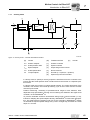
Figure 5: Use of the process data objects OutputData1 and InputData1
28
Sync unit
61221AXX
Manual – Fieldbus Interface DFE24B EtherCAT
Configuration and Startup
Configuring the EtherCAT master for MOVIDRIVE® B with the XML file
I
5
0
Static PDO for 10
cyclic process
data words
acycl. Mailbox cycl. OutputData1
Communication (Standard 10 PO)
PO 1
PO 2
PO 3
PO 4
MOVIDRIVE®
Process Data 1...3 or
®
IPOSplus Process Data 1...3
PO 5
PO 6
PO 7
PO 8
PO 9 PO 10
MOVIDRIVE®
®
IPOSplus Process Data 4...10
61223AXX
Figure 6: Assignment of standard process output data for OutputData1
The process output data transferred with OutputData1 are assigned according to the following table. The process output data PO1 ... PO3 can be connected with various
process data (control words, setpoints) using the process data configuration in the
MOVIDRIVE® B drive inverter (→ "MOVIDRIVE® Fieldbus Unit Profile" manual). The
process output data PO4 ... PO10 are only available in IPOSplus®.
Fixed assignments of the configured process
output data for
PDO OutputData1
Index.Subindex
Offset in PDO
Name
Data type
3DB8.0hex
(15800.0dec)
0.0
PO1
UINT
3DB9.0hex
(15801.0dec)
2.0
PO2
UINT
3DBA.0hex
(15802.0dec)
4.0
PO3
UINT
3DBB.0hex
(15803.0dec)
6.0
PO4
UINT
3DBC.0hex
(15804.0dec)
8.0
PO5
UINT
3DBD.0hex
(15805.0dec)
10.0
PO6
UINT
3DBE.0hex
(15806.0dec)
12.0
PO7
UINT
3DBF.0hex
(15807.0dec)
14.0
PO8
UINT
3DC0.0hex
(15808.0dec)
16.0
PO9
UINT
3DC1.0hex
(15809.0dec)
18.0
PO10
UINT
Manual – Fieldbus Interface DFE24B EtherCAT
Size in bytes
2
29
5
I
Configuration and Startup
Configuring the EtherCAT master for MOVIDRIVE® B with the XML file
0
Fixed assignment
of the configured
process input data
for PDO
InputData1
MOVIDRIVE®
Process Data 1...3 or
®
IPOSplus Process Data 1...3
PI 1
PI 2
PI 3
MOVIDRIVE®
®
IPOSplus Process Data 4...10
PI 4
PI 5
PI 6
PI 7
PI 8
PI 9
PI 10
cycl. InputData1 acycl. Mailbox
(Standard 10 PI) Communication
61226AXX
Figure 7: Assignment of the standard process input data for PDO InputData1
The process input data transferred with InputData1 are assigned according to the
following table. The process input data PI1 ... PI3 can be connected with various process
data (status words, actual values) using the process data configuration in the
MOVIDRIVE® B drive inverter (→ "MOVIDRIVE® Fieldbus Unit Profile" manual). The
process input data PI4 ... PI10 are only available in IPOSplus®.
Index.Subindex
Offset in PDO
Name
Data type
3E1C.0hex
(15900.0dec)
0.0
PI1
UINT
3E1D.0hex
(15901.0dec)
2.0
PI2
UINT
3E1E.0hex
(15902.0dec)
4.0
PI3
UINT
3E1F.0hex
(15903.0dec)
6.0
PI4
UINT
3E20.0hex
(15904.0dec)
8.0
PI5
UINT
3E21.0hex
(15905.0dec)
10.0
PI6
UINT
3E22.0hex
(15906.0dec)
12.0
PI7
UINT
3E23.0hex
(15907.0dec)
14.0
PI8
UINT
3E24.0hex
(15908.0dec)
16.0
PI9
UINT
3E25.0hex
(15909.0dec)
18.0
PI10
UINT
Size in bytes
2
If fewer than 10 process data words are to be transferred, or if the PDO mapping is to
be adjusted, the configurable PDOs are to be used instead of the static PDO.
30
Manual – Fieldbus Interface DFE24B EtherCAT
Configuration and Startup
Configuring the EtherCAT master for MOVIDRIVE® B with the XML file
I
5
0
Configurable PDO
for up to 8 IPOSplus® variables and
10 process data
words
The process data transferred with OutputData2 and InputData2 can be configured as required with process data information according to the following table. 32-bit variables of
type DINT and standard process data PO1 ... PO10 and PI1 ... PI10 can be configured.
In this way, the PDO can be configured to suit any application.
Ethernet
Header
Frame
Header
EtherCAT
Data
Header
Drive
...
EtherCAT
Master
SEW
Drive
acycl. Mailbox cycl. OutputData2
Communication (Configurable PO)
EtherCAT
FCS
cycl. InputData2 acycl. Mailbox
(Configurable PI) Communication
61230AXX
Figure 8: Use of the configurable PDO OutputData2, InputData2
acycl. Mailbox cycl. OutputData2
Communication (Configurable PO)
PO1
1. Variable
PO2
max. 10 Process Data
PO1..10(UINT)
6. Variable
7. Variable
PO10
8. Variable
®
max. 8 IPOSplus
Variables (DINT)
61232AXX
Figure 9: Configurable PDO mapping for OutputData2
max. 10 Process Data
PI1..10(UINT)
1. Variable
PI1
2. Variable
®
max. 8 IPOSplus
Variables (DINT)
7. Variable
PI10
8. Variable
cycl. InputData2
acycl. Mailbox
(Configurable PI) Communication
Figure 10: Configurable PDO mapping for InputData2
Manual – Fieldbus Interface DFE24B EtherCAT
61237AXX
31
5
I
Configuration and Startup
Configuring the EtherCAT master for MOVIDRIVE® B with the XML file
0
Assignment of the
configurable
process input and
output data for
PDO OutputData2
and InputData2
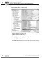
32
The maximum amount of configurable PDO OutputData2 and InputData2 data is
•
10 process data words (type UINT)
•
8 IPOSplus® variables (type DINT)
Index.Subindex
Name
Data
type
2AF8.0hex
(11000.0dec)
Template IposVar (0...1023)
Template for IPOSplus® variables
2CBD.0hex
(11453.0dec)
ModuloCtrl
(H453)
Control word of the Modulo function
2CBE.0hex
(11454.0dec)
ModTagPos
(H454)
Modulo target position
2CBF.0hex
(11455.0dec)
ModActPos
(H455)
Modulo actual position
2CC0.0hex
(11456.0dec)
ModCount
(H456)
Modulo counter value
2CD1.0hex
(11473.0dec)
StatusWord
(H473)
IPOS status word
2CD2.0hex
(11474dec)
Scope474
Direct Scope variable
2CD3.0hex
(11475.0dec)
Scope475
H475)
Direct Scope variable
2CD6.0hex
(11478.0dec)
AnaOutIPOS2
(H478)
Analog output 2 option DIO11B
2CD7.0hex
(11478.0dec)
AnaOutIPOS
(H479)
Analog output option DIO11B
2CD8.0hex
(11480.0dec)
OptOutIPOS
(H480)
Optional digital outputs
2CD9.0hex
(11481.0dec)
StdOutIPOS
(H481)
2CDA.0hex
(11482.0dec)
OutputLevel
(H482)
Status of the digital outputs
2CDB.0hex
(11483.0dec)
InputLevel
(H483)
Status of the digital inputs
2CDC.0hex
(11484.0dec)
ControlWord
(H484)
IPOSplus® control word
2CE4.0hex
(11492.0dec)
TargetPos
(H492)
Target position
2CE7.0hex
(11495.0dec)
LagDistance
(H495)
Lag distance
2CEB.0hex
(11499.0dec)
SetpPosBus
(H499)
Bus position setpoint
2CEC.0hex
(11500.0dec)
TpPos2_VE
(H500)
Touch probe position 2 virtual
encoder
2CED.0hex
(11501.0dec)
TpPos1_VE
(H501)
Touch probe position 1 virtual
encoder
2CEE.0hex
(11502.0dec)
TpPos2_Abs
(H502)
Touch probe position 2
2CEF.0hex
(11503dec)
TpPos1_Abs
(H503)
Touch probe position 1
DINT
Size in
bytes
4
Read
Write
4
Access attribute
Standard digital outputs
Manual – Fieldbus Interface DFE24B EtherCAT
Configuration and Startup
Configuring the EtherCAT master for MOVIDRIVE® B with the XML file
I
5
0
Index.Subindex
Name
2CF0.0hex
(11504.0dec)
TpPos2_Ext
(H504)
Touch probe position 2 external
2CF1.0hex
(11505.0dec)
TpPos2_Mot
(H505)
Touch probe position 2 motor
encoder
2CF2.0hex
(11506.0dec)
TpPos1_Ext
(H506)
Touch probe position 1 external
2CF3.ohex
(11507.0dec)
TpPos1_Mot
(H507)
Touch probe position 1 motor
2CF4.0hex
(11508.0dec)
ActPos_Mot16
bit (H508)
2CF5.0hex
(11509dec)
ActPos_Abs
(H509)
Actual position absolute encoder
2CF6.0hex
(11510.0dec)
ActPos_Ext
(H510)
Actual position external encoder
X14
2CF7.0hex
(11511.0dec)
ActPos_Mot
(H511)
Actual position motor encoder
3DB8.0hex
(15800.0dec)
PO1
Standard process output data word
PO1
3DB9.0hex
(15801.0dec)
PO2
Standard process output data word
PO2
3DBA.0hex
(15802.0dec)
PO3
Standard process output data word
PO3
3DBB.0hex
(15803.0dec)
PO4
Standard process output data word
PO4
3DBC.0hex
(15804.0dec)
PO5
Standard process output data word
PO5
3DBD.0hex
(15805.0dec)
PO6
Standard process output data word
PA6
3DBE.0hex
(15806.0dec)
PO7
Standard process output data word
PO7
3DBF.0hex
(15807.0dec)
PO8
Standard process output data word
PO8
3DC0.0hex
(15808.0dec)
PO9
Standard process output data word
PO9
3DC1.0hex
(15801.0dec)
PO10
Standard process output data word
PO10
3E1C.0hex
(15900.0dec)
PI1
3E1D.0hex
(1590010dec)
PI2
Standard process input data word
PI2
3E1E.0hex
(15902.0dec)
PI3
Standard process input data word
PI3
3E1F.0hex
(15903.0dec)
PI4
Standard process input data word
PI4
3E20.0hex
(15904.0dec)
PI5
Standard process input data word
PI5
3E21.0hex
(15905.0dec)
PI6
Standard process input data word
PI6
3E22.0hex
(15906.0dec)
PI7
Standard process input data word
PI7
3E23.0hex
(15907.0dec)
PI8
Standard process input data word
PI8
3E24.0hex
(15908.0dec)
PI9
Standard process input data word
PI9
3E25.0hex
(15909.0dec)
PI10
Standard process input data word
PI10
Manual – Fieldbus Interface DFE24B EtherCAT
Data
type
DINT
UINT
Size in
bytes
4
2
Read
Write
4
2
Access attribute
Actual position motor 16 Bit
Standard process input data word
PI1
33
5
I
Configuration and Startup
Configuring the EtherCAT master for MOVIDRIVE® B with the XML file
0
Plausibility of the configuration of process data objects:
34
•
In the freely configurable process data objects OutputData2 and InputData2, cyclical
process output data PO1 ... 10 cannot be inserted when OutputData1 or InputData1
is configured at the same time.
•
Multiple configuration of process data objects is not possible.
•
Only standard process data objects PO1 ... PO10, PI1 ... PI10 or IPOSplus® variables
(indices 11000.0 ... 12023.0) can be configured as process data.
Manual – Fieldbus Interface DFE24B EtherCAT
Configuration and Startup
Configuring the EtherCAT master for MOVITRAC® B / gateway with XML file
I
5
0
5.3
Configuring the EtherCAT master for MOVITRAC® B / gateway with XML file
This section describes the configuration of the EtherCAT master with MOVITRAC® B
and the DFE24B gateway / UOH11B.
5.3.1
XML files for operation in MOVITRAC® B and gateway housing UOH11B
An XML file (SEW_DFE24B.XML) is available for configuring the EtherCAT master.
Copy this file to a folder in the configuration software.
Refer to the manuals for the appropriate configuration software for details on this
procedure.
The XML files standardized by the EtherCAT Technology Group (ETG) can be read by
all EtherCAT masters.
5.3.2
Configuration procedure
Proceed as follows to configure MOVITRAC® / gateways with the EtherCAT interface:
1. Install (copy) the XML file according to the specifications of your configuration software. Once the file has been installed correctly, the device appears next to the slave
stations (under SEW EURODRIVE → Drives) with the designation DFE24BGateway.
2. Use the [Insert] menu item to add the device to the EtherCAT structure. The address
is assigned automatically. You can give the device a name to make it easier to
identify.
3. Connect the I/O or periphery data to the input and output data of the application
program.
Once configuration is complete, you can start EtherCAT communication. The LEDs
RUN and ERR indicate the communication status of option DFE24B (see section 4.9
"Operating displays of the DFE24B option").
Manual – Fieldbus Interface DFE24B EtherCAT
35
I
5
Configuration and Startup
Configuring the EtherCAT master for MOVITRAC® B / gateway with XML file
0
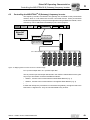
5.3.3
PDO configuration for DFE24B gateway for MOVITRAC® B
In the DFE24B gateway operating mode for MOVITRAC® B, one PDO each is used for
cyclical process input and output data.
•
OutputData1 (Standard 24 PO)
Static PDO with 24 cyclical process output data words that are connected in fixed
configuration with the process data of a maximum of 8 MOVITRAC® B connected to
the gateway.
•
InputData1 (Standard 24 PI)
Static PDO with 24 cyclical process input data words that are connected in fixed
configuration with the process data of a maximum of 8 MOVITRAC® B connected to
the gateway.
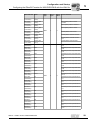
List of the possible PDO for the DFE24B gateway:
Ethernet
Header
Index
Size
Name
Mapping
1601hex
(5633dec)
48 bytes
OutputData1 (Standard 24 PO)
Fixed
content
2
0
1A01hex
(5633dec)
48 bytes
InputData1 (Standard 24 PI)
Fixed
content
3
0
Frame
Header
EtherCAT
Data
Header
Drive
...
EtherCAT
Master
Sync unit
FCS
DFE 24B
RUN
acycl. Mailbox cycl. OutputData1
Communication (Standard 24 PO)
EtherCAT
Sync manager
ERR
cycl. InputData1 acycl. Mailbox
(Standard 24 PI) Communication
0
1
AS
F1
X31
OUT
X30
IN
EtherCAT
MOVITRAC® B
Unit = SBus-Address:
1
EURODRIVE
2
EURODRIVE
3
EURODRIVE
Figure 11: Data exchange (PDO OutputData1, InputData1) with EtherCAT master
36
4
EURODRIVE
5
EURODRIVE
6
EURODRIVE
7
EURODRIVE
8
EURODRIVE
61242AXX
Manual – Fieldbus Interface DFE24B EtherCAT
Configuration and Startup
Configuring the EtherCAT master for MOVITRAC® B / gateway with XML file
I
5
0
Assignment of the fixed configured process output data (PDO 1)
acycl. Mailbox cycl. OutputData1
Communication (Standard 10 PO)
PO1
PO2
PO3
PO4
Drive 1
PO1...PO3
PO5
PO6
Drive 2
PO1...PO3
PO22 PO23 PO24
Drive 8
PO1...PO3
Figure 12: Assignment of standard process output data for OutputData1
61239AXX
The process output data transferred with OutputData1 are assigned according to the following table. For each inverter, the process output data PO1 ... PO3 can be connected
with various process data (control words, setpoints) using the process data configuration in the MOVITRAC® B drive inverter (→ "MOVITRAC® B" operating instructions).
Index.Subindex
Offset in PDO
Name
Assignment
3DB8.0hex
(15800.0dec)
0.0
PO1
Drive 1 PO1
3DB9.0hex
(15801.0dec)
2.0
PO2
Drive 1 PO2
3DBA.0hex
(15802.0dec)
4.0
PO3
Drive 1 PO3
3DBB.0hex
(15803.0dec)
6.0
PO4
Drive 2 PO1
3DBC.0hex
(15804.0dec)
8.0
PO5
Drive 2 PO2
3DBD.0hex
(15805.0dec)
10.0
PO6
Drive 2 PO3
3DBE.0hex
(15806.0dec)
12.0
PO7
Drive 3 PO1
3DBF.0hex
(15807.0dec)
14.0
PO8
Drive 3 PO2
3DC0.0hex
(15808.0dec)
16.0
PO9
Drive 3 PO3
3DC1.0hex
(15809.0dec)
18.0
PO10
Drive 4 PO1
3DC2.0hex
(15810.0dec)
0.0
PO11
Drive 4 PO2
3DC3.0hex
(15811.0dec)
2.0
PO12
Drive 4 PO3
3DC4.0hex
(15812.0dec)
4.0
PO13
Drive 5 PO1
3DC5.0hex
(15813.0dec)
6.0
PO14
Drive 5 PO2
3DC6.0hex
(15814.0dec)
8.0
PO15
Drive 5 PO3
Manual – Fieldbus Interface DFE24B EtherCAT
Data type
UINT
Size in bytes
2
37
5
I
Configuration and Startup
Configuring the EtherCAT master for MOVITRAC® B / gateway with XML file
0
38
Index.Subindex
Offset in PDO
Name
Assignment
3DC7.0hex
(15815.0dec)
10.0
PO16
Drive 6 PO1
3DC8.0hex
(15816.0dec)
12.0
PO17
Drive 6 PO2
3DC9.0hex
(15817.0dec)
14.0
PO18
Drive 6 PO3
3DCA.0hex
(15818.0dec)
16.0
PO19
Drive 7 PO1
3DCB.0hex
(15819.0dec)
18.0
PO20
Drive 7 PO2
3DCC.0hex
(15820.0dec)
18.0
PO21
Drive 7 PO3
3DCD.0hex
(15821.0dec)
18.0
PO22
Drive 8 PO1
3DCE.0hex
(15822.0dec)
18.0
PO23
Drive 8 PO2
3DCF.0hex
(15823.0dec)
18.0
PO24
Drive 8 PO3
Data type
UINT
Size in bytes
2
Manual – Fieldbus Interface DFE24B EtherCAT
Configuration and Startup
Configuring the EtherCAT master for MOVITRAC® B / gateway with XML file
I
5
0
Assignment of the fixed configured process input data (PDO 1)
Drive 1
PI1...PI3
PI1
PI2
Drive 2
PI1...PI3
PI3
PI4
PI5
Drive 8
PI1...PI3
PI6
PI22
PI23
PI24
cycl. InputData1 acycl. Mailbox
(Standard 10 PI) Communication
61240AXX
Figure 13: Assignment of the standard process input data for InputData1
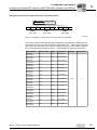
The process input data transferred with InputData1 are assigned according to the
following table. The process input data PI1 ... PI3 can be connected with various process
data (status words, actual values) using the process data configuration in the
MOVITRAC® B drive inverter (→ "MOVITRAC® B" operating instructions).
Index.Subindex
Offset in PDO
Name
Assignment
3E1C.0hex
(15900.0dec)
0.0
PI1
Drive 1 PI1
3E1D.0hex
(15901.0dec)
2.0
PI2
Drive 1 PI2
3E1E.0hex
(15902.0dec)
4.0
PI3
Drive 1 PI3
3E1F.0hex
(15903.0dec)
6.0
PI4
Drive 2 PI1
3E20.0hex
(15904.0dec)
8.0
PI5
Drive 2 PI2
3E21.0hex
(15905.0dec)
10.0
PI6
Drive 2 PI3
3E22.0hex
(15906.0dec)
12.0
PI7
Drive 3 PI1
3E23.0hex
(15907.0dec)
14.0
PI8
Drive 3 PI2
3E24.0hex
(15908.0dec)
16.0
PI9
Drive 3 PI3
3E25.0hex
(15909.0dec)
18.0
PI10
Drive 4 PI1
3E26.0hex
(15910.0dec)
20.0
PI11
Drive 4 PI2
3E27.0hex
(15911.0dec)
22.0
PI12
Drive 4 PI3
3E28.0hex
(15912.0dec)
24.0
PI13
Drive 5 PI1
3E29.0hex
(15913.0dec)
26.0
PI14
Drive 5 PI2
3E2A.0hex
(15914.0dec)
28.0
PI15
Drive 5 PI3
Manual – Fieldbus Interface DFE24B EtherCAT
Data type
UINT
Size in bytes
2
39
5
I
Configuration and Startup
Configuring the EtherCAT master for MOVITRAC® B / gateway with XML file
0
40
Index.Subindex
Offset in PDO
Name
Assignment
Data type
Size in bytes
3E2B.0hex
(15915.0dec)
30.0
PI16
Drive 6 PI1
UINT
2
3E2C.0hex
(15916.0dec)
32.0
PI17
Drive 6 PI2
3E2D.0hex
(15917.0dec)
34.0
PI18
Drive 6 PI3
3E2E.0hex
(15918.0dec)
36.0
PI19
Drive 7 PI1
3E2F.0hex
(15919.0dec)
38.0
PI20
Drive 7 PI2
3E30.0hex
(15920.0dec)
40.0
PI21
Drive 7 PI3
3E31.0hex
(15921.0dec)
42.0
PI22
Drive 8 PI1
3E32.0hex
(15922.0dec)
44.0
PI23
Drive 8 PI2
3E33.0hex
(15923.0dec)
46.0
PI24
Drive 8 PI3
Manual – Fieldbus Interface DFE24B EtherCAT
Configuration and Startup
Configuring the EtherCAT master for MOVITRAC® B / gateway with XML file
I
5
0
5.3.4
Auto setup for gateway operation
The auto setup function can be used to startup DFE24B as a gateway without a PC. The
function is activated using the DIP switch Auto-Setup (see section 4.4 on page 19) .
Setting the DIP switch Auto-Setup (AS) from OFF to ON position causes the function to
be executed once. The Auto-Setup DIP switch must then remain in ON position.
The function can be reactivated by turning the DIP switch off and back on again.
First, the DFE24B searches on the lower-level SBus for SEW drives. This process is indicated by the LED H1 (system error) flashing briefly. For this purpose, different SBus
addresses must be set for the drive inverters (P881). We recommend assigning the
addresses beginning with address 1 in ascending order based on the arrangement of
inverters in the control cabinet. The process image on the fieldbus side is expanded by
three words for each detected drive inverter.
The LED H1 remains lit if no drive inverter is located. A total of up to 8 drive inverters is
taken into account.
After the search is completed, the DFE24B cyclically exchanges 3 process data words
with each connected drive inverter. The process output data is taken from the fieldbus,
divided into blocks of three and transmitted. The drive inverters read the process input
data, put it together and send it to the fieldbus master.
The cycle time of SBus communication is 2 ms per station.
For an application with 8 inverters on the SBus, the cycle time for the process data
update will be 8 x 2 ms = 16 ms.
If you change the process data assignment of the drive inverters connected to DFE24B,
you must activate Auto-Setup again because the DFE24B saves these values only once
during Auto-Setup. At the same time, the process data assignments of the connected
drive inverters may not be changed dynamically after Auto-Setup.
Manual – Fieldbus Interface DFE24B EtherCAT
41
I
5
Configuration and Startup
Setting the MOVIDRIVE® MDX61B drive inverter
0
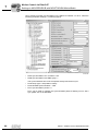
5.4
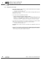
Setting the MOVIDRIVE® MDX61B drive inverter
The following settings must be made for simple fieldbus operation.
11638AXX
However, to control the MOVIDRIVE® B drive inverter via EtherCAT, you must first
switch the drive inverter to control signal source (P101) and setpoint source (P100) =
FIELDBUS. The FIELDBUS setting means the drive inverter parameters are set for
control and setpoint entry via EtherCAT. The MOVIDRIVE® B drive inverter now
responds to the process output data transmitted from the PLC.
The parameters of the MOVIDRIVE® B drive inverter can be set straight away via EtherCAT without any further settings once the EtherCAT option card has been installed. For
example, all parameters can be set by the master programmable controller after poweron.
42
Manual – Fieldbus Interface DFE24B EtherCAT
Configuration and Startup
Setting the MOVITRAC® frequency inverter
I
5
0
Activation of the control signal source and setpoint source FIELDBUS is signaled to the
machine controller using the "Fieldbus mode active" bit in the status word.
For safety reasons, you must also enable the MOVIDRIVE® B drive inverter at the
terminals for control via the fieldbus system. Consequently, you must wire and program
the terminals in such a way that the inverter is enabled via the input terminals. The
simplest way of enabling the inverter on the terminal side is to set the DIØØ input
terminal (Function /CONTROLLER INHIBIT) to a +24 V signal and to program the input
terminals DIØ1 ... DIØ7 to NO FUNCTION.
The whole procedure for starting up the MOVIDRIVE® B drive inverter with EtherCAT
connection is described in sections 6 and 7.
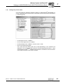
5.5
Setting the MOVITRAC® frequency inverter
11639AXX
Manual – Fieldbus Interface DFE24B EtherCAT
43
5
I
Configuration and Startup
Setting the MOVITRAC® frequency inverter
0
To control the MOVITRAC® B frequency inverter via EtherCAT, you must first switch the
inverter to Control signal source (P101) and Setpoint source (P100) = SBus. The SBus
setting means the MOVITRAC® B frequency inverter parameters are set for setpoint
transfer from the gateway. The MOVITRAC® B frequency inverter now responds to the
process output data transmitted from the PLC.
To ensure that the MOVITRAC® B frequency inverter stops when SBus communication
is interrupted, set the SBus1 timeout time (P883) to a value other than 0 ms. We
recommend a value between 50 and 200 ms.
Activation of the control signal source and setpoint source SBus is signaled to the
machine controller using the "SBus mode active" bit in the status word.
For safety reasons, you must also enable the frequency inverter at the terminals for
control via the fieldbus system. Consequently, you must wire and program the terminals
in such a way that the inverter is enabled via the input terminals. The simplest way of
enabling the frequency inverter on the terminal side is to set the DIØØ input terminal
(function CW/STOP) to a +24 V signal and to program the other input terminals to NO
FUNCTION.
Configure the parameter P881 SBus address to values 1 ... 8 in ascending order.
SBus address 0 is used by the DFE24B gateway, and so cannot be used here.
Configure the parameter P883 SBus timeout to values 50 ... 200 ms.
44
Manual – Fieldbus Interface DFE24B EtherCAT
EtherCAT Operating Characteristics
Controlling the MOVIDRIVE® MDX61B drive inverter
I
6
0
6
EtherCAT Operating Characteristics
This section describes the basic characteristics of the drive inverter on EtherCAT with
control via fixed PDO for fieldbus communication (motion control applications → Sec. 7).
6.1
Controlling the MOVIDRIVE® MDX61B drive inverter
The MOVIDRIVE® B drive inverter is controlled using the fixed PDO, which are 10 I/O
words long. These process data words are mapped directly in the process image when
using an EtherCAT master, which means they can be addressed directly by the control
program.
EtherCAT
Master
Ethernet
Header
Frame
Header
SEW
Drive
EtherCAT
Data
Header
SEW
Drive
SEW
Drive
Drive 1 Drive 2 Drive 3
I/O
...
FCS
EtherCAT
Figure 14: EtherCAT with SEW Drives
61375AXX
For more information on controlling via the process data channel, in particular the coding
of the control and status words, refer to the "Fieldbus Unit Profile" manual.
Manual – Fieldbus Interface DFE24B EtherCAT
45
I
6
EtherCAT Operating Characteristics
Controlling the MOVIDRIVE® MDX61B drive inverter
0
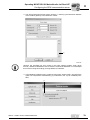
6.1.1
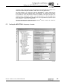
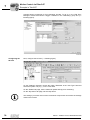
Control example in TwinCAT with MOVIDRIVE® MDX61B
Once the SEW_DFE24B.xml file has been copied to the TwinCAT subdirectory
"\IO\EtherCAT", you can use the function "Append box" to insert a MOVIDRIVE® B unit
in the EtherCAT structure (→ following figure).
11641AXX
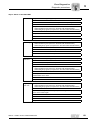
In "online mode" (i.e. when connected with the EtherCAT line), you can use the symbol
"Find devices" to search the EtherCAT line for connected MOVIDRIVE® units (→
following figure).
11642AXX
For simple fieldbus functionality, NC axes do not necessarily have to be created for each
device that is found.
46
Manual – Fieldbus Interface DFE24B EtherCAT
EtherCAT Operating Characteristics
Controlling the MOVIDRIVE® MDX61B drive inverter
I
6
0
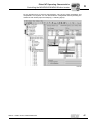
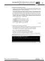
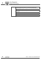
For the simplest form of process data transport, only the two PDOs InputData1 and
OutputData1 are required. You can deactivate the configurable PDOs by deleting the
marker for both PDOs (Input and Output) (→ following figure).
11643AXX
Manual – Fieldbus Interface DFE24B EtherCAT
47
I
6
EtherCAT Operating Characteristics
Controlling the MOVIDRIVE® MDX61B drive inverter
0
Now, you can either connect up to 10 process data words with the PLC program or - as
shown in the following figure - write them for manual testing.
11644AXX
First select process output data PO1. In the window that appears, choose the tab page
"Online". Click "Write". The "Set Value Dialog" window opens. Enter your data in the
"Dec" or "Hex" field. Repeat the procedure for process output data PO2.
The 10 process input and output data words are assigned and scaled in MOVIDRIVE® B
in the 87_ parameter group or defined via an IPOSplus® program or application module.
For more information, refer to the "MOVIDRIVE® MDX60B/61B" system manual and the
"Fieldbus Unit Profile" manual.
6.1.2
EtherCAT timeout (MOVIDRIVE® MDX61B)
If data transfer via EtherCAT is disturbed or interrupted, the fieldbus monitoring time
(standard value 100 ms) configured in the master elapses in MOVIDRIVE® MDX61B.
The DFE24B ERR LED signals that no new user data can be received. At the same
time, MOVIDRIVE® MDX61B performs the fault response selected with P831 Fieldbus
timeout response.
P819 Fieldbus timeout displays the monitoring time specified by the master during the
EtherCAT startup. The duration of the timeout can only be changed via the master. Modifications made using the keypad or MOVITOOLS® do not have any effect and are overwritten during the next startup of the PLC.
6.1.3
Fieldbus timeout response (MOVIDRIVE® MDX61B)
Parameter P831 Fieldbus timeout delay is used to set the fault response that is triggered
via the fieldbus timeout monitoring function. The setting made here must match the configuration of the master system.
48
Manual – Fieldbus Interface DFE24B EtherCAT
EtherCAT Operating Characteristics
Controlling the MOVITRAC® B (Gateway) frequency inverter
I
6
0
6.2
Controlling the MOVITRAC® B (Gateway) frequency inverter
The frequency inverters connected to the gateway are controlled via the process data
channel, which is 3 I/O data words for each connected inverter. These process data
words are mapped directly in the process image when using an EtherCAT master, which
means they can be addressed immediately by the control program.
Ethernet
Header
Frame
Header
EtherCAT
Data
Header
Drive
...
EtherCAT
Master
FCS
DFE 24B
RUN
acycl. Mailbox cycl. OutputData1
Communication (Standard 24 PO)
EtherCAT
ERR
cycl. InputData1 acycl. Mailbox
(Standard 24 PI) Communication
0
1
AS
F1
X31
OUT
X30
IN
EtherCAT
MOVITRAC® B
Unit = SBus-Address:
1
EURODRIVE
2
EURODRIVE
3
EURODRIVE
4
EURODRIVE
5
EURODRIVE
6
EURODRIVE
7
EURODRIVE
Figure 15: Mapping EtherCAT data in the PLC address range
8
EURODRIVE
61242AXX
PO = process output data / PI = process input data
The 24 process input and output data words in the PDO are transmitted from the gateway to up to 8 inverters connected via SBus as follows:
•
Words 1, 2 and 3 to the inverter with the lowest SBus address (e.g. 1)
•
Words 4, 5 and 6 to the inverter with the next highest SBus address (e.g. 2)
•
....
If fewer than 8 frequency inverters are connected to the gateway, the upper words in the
PDO have no significance - they are not transmitted to any inverter.
Manual – Fieldbus Interface DFE24B EtherCAT
49
I
6
EtherCAT Operating Characteristics
Controlling the MOVITRAC® B (Gateway) frequency inverter
0
6.2.1
Control example in TwinCAT with MOVITRAC® B (gateway)
Once the SEW_DFE24B.xml file has been copied to the TwinCAT subdirectory
"\IO\EtherCAT", you can use the function "Append box" to insert a DFE24B gateway in
the EtherCAT structure (→ following figure).
11645AXX
In "online mode" (i.e. when connected with the EtherCAT line), you can use the symbol
"Find devices" to search the EtherCAT line for connected DFE24B gateways (→
following figure).
11642AXX
It is not a good idea to create an NC axis for each DFE24B gateway that is found. In this
case, an axis would have to be created for every MOVITRAC® B inverter connected to
the DFE24B gateway. For simple fieldbus functionality, NC axes do not necessarily
have to be created for each device that is found.
50
Manual – Fieldbus Interface DFE24B EtherCAT
EtherCAT Operating Characteristics
Controlling the MOVITRAC® B (Gateway) frequency inverter
I
6
0
The first 3 process data words are exchanged with the first MOVITRAC® B unit on the
DFE24B gateway. They can be connected to the PLC program or written for manual
testing (→ following figure).
11646AXX
First select process output data PO1. In the window that appears, choose the tab page
"Online". Click "Write". The "Set Value Dialog" window opens. Enter your data in the
"Dec" or "Hex" field. Repeat the procedure for process output data PO2.
The 3 process input and output data words are assigned and scaled in MOVITRAC® B
in the 87_ parameter group or defined via an IPOSplus® program. For more information,
refer to the "MOVITRAC® B" system manual and the "MOVITRAC® Communication"
manual.
6.2.2
SBus timeout
If one or several drive inverters on the SBus can no longer be addressed by the
DFE24B, the gateway displays error code F111 System error on status word 1 of the
respective drive inverter. LED H1 (system fault) lights up. The fault is also displayed via
diagnostics interface X24. The SBus timeout time (P883) of the MOVITRAC® B system
error must be set to a value other than 0 for the drive inverter to stop. The timeout
response can be defined via parameter P836.
6.2.3
Unit faults
Gateways detect a series of hardware defects automatically and lock out as a result. The
exact error responses and remedies can be found in the list of errors. If an error occurs
during a self-test, the fault F111 System error is displayed on the fieldbus process input
data for status words 1 of all drive inverters. In this case, LED H1 (system error) flashes
at regular intervals on the DFE24B. The exact error code is displayed in the status of the
gateway with MOVITOOLS® MotionStudio using diagnostics interface X24.
Manual – Fieldbus Interface DFE24B EtherCAT
51
I
6
EtherCAT Operating Characteristics
Configuration via EtherCAT
0
6.2.4
DFE24B fieldbus timeout in gateway operation
You can use the parameter P831 Fieldbus timeout response to set how the gateway
should respond when EtherCAT communication times out.
6.3
P831 Fieldbus timeout response
Description
No response
The drives connected via SBus continue to work with the last
setpoint.
The drives cannot be controlled any longer when EtherCAT communication is interrupted.
PO_DATA = 0
When an EtherCAT timeout is detected, a rapid stop is activated for
all drives that have process data configuration with control word 1 or
2. To do so, the gateway sets bits 0 ... 2 of the control word to 0.
The drives are brought to a standstill using the rapid stop ramp.
Configuration via EtherCAT
With EtherCAT, the drive parameters are accessed via the standard SDO READ and
WRITE services in CoE (CANopen over EtherCAT).
Inverter configuration using the EtherCAT parameter channel is only possible for
MOVIDRIVE® MDX61B and the parameters of the DFE24B gateway.
At present, the EtherCAT SDO parameter channel does not enable access to parameters on inverters connected via SBus to the gateway.
Via VoE (Vendor-specific over EtherCAT), MOVITOOLS® MotionStudio can also
access MOVITRAC® B inverters connected to the gateway via SBus (→ Sec. 8).
6.3.1
SDO READ and WRITE services
The user interface is displayed differently depending on the EtherCAT master or
configuration environment. However, the following parameters are always required to
execute the SDO command.
SDO-READ
Description
Slave address (16 bit)
EtherCAT address of the inverter from which data is to be read.
Index (16 bit)
Subindex (8 bit)
Address in the object dictionary that is to be read.
Data
Data length
Structure to store received data and its length.
SDO-WRITE
Description
Slave address (16 bit)
EtherCAT address of the inverter to which data is to be written.
Index (16 bit)
Subindex (8 bit)
Address in the object dictionary that is to be written.
Data
Data length
Structure in which the data to be written is stored.
Additional flags and parameters may also be required for the READ and WRITE SDO
services:
52
•
to activate the function
•
to display in-process messages or error messages
•
to monitor timeout times
•
to report errors in the execution
Manual – Fieldbus Interface DFE24B EtherCAT
EtherCAT Operating Characteristics
Configuration via EtherCAT
I
6
0
6.3.2
Example of reading a parameter in TwinCAT via EtherCAT
The function SDO-READ is available for reading parameters. The index of the
parameter to be read is required. You can display the parameter index in the SHELL
program or in the parameter tree using the key combination [CTRL + F1].
The function module FB_EcCoESdoRead is required for implementation in TwinCAT.
This function module is included in the TcEtherCAT.lib library. This function module can
be integrated in two steps.
1. Create an instance of the FB_EcCoESdoRead function module
2. The inputs of the function modules are assigned as follows:
–
–
–
–
–
–
–
–
sNetID: Net ID of the EtherCAT master
nSlaveAddr: EtherCAT address of the SEW device from which data is to be read.
nIndex: Index of the parameter to be read.
nSubIndex: Subindex of the parameter to be read.
pDstBuf: Pointer to the data range in which the read parameter is to be stored.
cbBufLen: Maximum memory size in bytes for the parameter that is to be read.
bExecute: A positive edge starts the reading process.
tTimeout: Timeout time of the function module.
The output flags bBusy and bError indicate the status of the service. nErrId shows the
error number when the bError flag is set if an error occurs.
Manual – Fieldbus Interface DFE24B EtherCAT
53
6
I
EtherCAT Operating Characteristics
Configuration via EtherCAT
0
The figure below shows the process of integrating the function module in TwinCAT:
11647AXX
SEW parameters always have a data length of 4 bytes (1 DWord). Refer to the "Fieldbus
Unit Profile" manual for more details and information on scaling.
In the above example, the DC link voltage was read (index 8325, subindex 0). For
example, the value 639000 is received, which - according to the fieldbus unit profile corresponds to a voltage of 639 V.
54
Manual – Fieldbus Interface DFE24B EtherCAT
EtherCAT Operating Characteristics
Configuration via EtherCAT
I
6
0
6.3.3
Example of writing a parameter in TwinCAT via EtherCAT
The function SDO-WRITE is available for writing parameters. The index of the parameter to be written is required. You can display the parameter index in the SHELL program
or in the parameter tree using the key combination [CTRL + F1].
The function module FB_EcCoESdoWrite is required for implementation in TwinCAT.
This function module is included in the TcEtherCAT.lib library. This function module can
be integrated in two steps.
1. Create an instance of the FB_EcCoESdoWrite function module
2. The inputs of the function modules are assigned as follows:
– sNetID: Net ID of the EtherCAT master
– nSlaveAddr: EtherCAT address of the SEW device from which data is to be
written.
– nIndex: Index of the parameter to be written.
– nSubIndex: Subindex of the parameter to be written.
– pDstBuf: Pointer to the data range in which the data to be written is located.
– cbBufLen: Amount of data to be sent, in bytes.
– bExecute: A positive edge starts the writing process.
– tTimeout: Timeout time of the function module.
The output flags bBusy and bError indicate the status of the service. nErrId shows the
error number when the bError flag is set if an error occurs.
The figure below shows the process of integrating the function module in TwinCAT:
11648AXX
Manual – Fieldbus Interface DFE24B EtherCAT
55
I
6
EtherCAT Operating Characteristics
Configuration return codes
0
SEW parameters always have a data length of 4 bytes (1 DWord). Refer to the "Fieldbus
Unit Profile" manual for more details and information on scaling.
In the above example, the internal setpoint n11 (index 8489, subindex 0) was set to a
speed of 100 rpm. In accordance with the fieldbus unit profile, the required speed must
be multiplied by a factor of 1000.
6.4
Configuration return codes
6.4.1
Elements
In the event of incorrect parameter service, the drive inverter sends back various return
codes to the master that sent the message. These codes provide detailed information
about what caused the error. Generally, these return codes are structured into the
following elements:
6.4.2
•
Error class
•
Error code
•
Additional code
Error class
The error class element (1 byte) provides a more exact classification of the error type.
6.4.3
Class (hex)
Designation
Meaning
1
vfd state
Status error of the virtual field device
2
application reference
Error in application program
3
definition
Definition error
4
resource
Resource error
5
service
Error during execution of service
6
access
Access error
7
ov
Error in the object list
8
other
Other error
Error code
The error code element (1 byte) provides a means of more precisely identifying the
cause of the error within the error class For Error class 8 = Other error, only Error code
= 0 (Other error code) is defined. In this case, detailed identification is made using the
additional code.
56
Manual – Fieldbus Interface DFE24B EtherCAT
EtherCAT Operating Characteristics
Configuration return codes
I
6
0
6.4.4
Additional code
The additional code (2 bytes) contains a detailed description of the error.
6.4.5
List of the error codes for SDO services
Error code
Error
class
Error
code
Additional
code
Designation
Description
0x00000000
0
0
0
NO_ERROR
No error.
0x05030000
5
3
0
TOGGLE_BIT_NOT_CHANGED
Error in toggle bit during segmented
transfer.
0x05040000
5
4
0
SDO_PROTOCOL_TIMEOUT
Timeout in the service execution.
0x05040001
5
4
1
COMMAND_SPECIFIER_UNKNOWN
Unknown SDO service.
0x05040005
5
4
5
OUT_OF_MEMORY
Memory overflow during SDO
service execution.
0x06010000
6
1
0
UNSUPPORTED_ACCESS
Unauthorized access to an index.
0x06010001
6
1
1
WRITE_ONLY_ENTRY
The index can be written but not
read.
0x06010002
6
1
2
READ_ONLY_ENTRY
Index can be read but not written.
Parameter lock is active.
0x06020000
6
2
0
OBJECT_NOT_EXISTING
Object does not exist; incorrect
index.
An option card is not available for
this index.
0x06040041
6
4
41
OBJECT_CANT_BE_PDOMAPPED
Index cannot be mapped in a PDO.
0x06040042
6
4
42
MAPPED_OBJECTS_EXCEED_PDO
Too many mapped objects for PDO.
0x06040043
6
4
43
PARAM_IS_INCOMPATIBLE
Incompatible data format for index.
0x06040047
6
4
47
INTERNAL_DEVICE_INCOMPATIBILITY
Internal device error.
0x06060000
6
6
0
HARDWARE ERROR
Internal device error.
0x06070010
6
7
10
PARAM_LENGTH_ERROR
Data format for the index is the
wrong size.
0x06070012
6
7
12
PARAM_LENGTH_TOO_LONG
Data format for the index is too long.
0x06070013
6
7
13
PARAM_LENGTH_TOO_SHORT
Data format for the index is too short.
0x06090011
6
9
11
SUBINDEX_NOT_EXISTING
Subindex has not been implemented.
0x06090030
6
9
30
VALUE_EXCEEDED
Invalid value.
0x06090031
6
9
31
VALUE_TOO_GREAT
Value too high.
0x06090032
6
9
32
VALUE_TOO_SMALL
Value too low.
0x06090036
6
9
36
MAX_VALUE_IS_LESS_THAN_MIN_VALUE
Upper limit for the value is smaller
than the lower limit.
0x08000000
8
0
0
GENERAL_ERROR
General error.
0x08000020
8
0
20
DATA_CANNOT_BE_READ_OR_STORED
Data access error
0x08000021
8
0
21
DATA_CANNOT_BE_READ_OR_STORED_
BECAUSE_OF_LOCAL_CONTROL
Data access error due to local
control.
0x08000022
8
0
22
DATA_CANNOT_BE_READ_OR_STORED_
IN_THIS_STATE
Data access error due to unit state.
0x08000023
8
0
23
NO_OBJECT_DICTIONARY_IS_PRESENT
There is no object dictionary.
Manual – Fieldbus Interface DFE24B EtherCAT
57
I
7
Motion Control via EtherCAT
Introduction to EtherCAT
0
7
Motion Control via EtherCAT
This section contains information on the EtherCAT functions that enable
MOVIDRIVE® B to be operated synchronously on an EtherCAT master for motion
control applications.
7.1
Introduction to EtherCAT
This section describes the functions and terms used for running SEW drive inverters on
EtherCAT in synchronous operation. More technical and comprehensive information on
EtherCAT is available from the EtherCAT User Organization at www.EtherCAT.org and
from the manufacturers of EtherCAT master systems.
The following section describes the basic mechanisms required for motion control applications, starting with cascade control, a typical feature of drive engineering.
[2]
[1]
xref
vref
xact
vact
[3]
tref
[4]
M
V
[5]
X
[5]
X
[6]
61477AXX
xref
Position setpoint
[1]
Position controller
xact
Actual position value
[2]
Speed controller
vref
Speed setpoint
[3]
Output stage of the inverter
vact
Actual speed value
[4]
Drive machine (load)
tref
Torque setpoint
[5]
Encoder (V = speed; X = position)
The process starts with a position setpoint (xref). Using this and the actual position value
(xact), the position controller [1] calculates a speed setpoint (vref). The speed controller
[2] uses this speed setpoint and actual speed value vact to calculate the torque setpoint
(tref) to create torque in the motor powered by the inverter [3]. A speed (measured using
encoder [5]) occurs in the motor depending on the counter-torque of the driven machine
[4]. A position change measured using the position sensors [5] or [6] results depending
on the motor speed.
Depending on the application, control loops for torque, speed or position can be closed
in the inverter or in a higher-level controller. MOVIDRIVE® B can handle all control
loops, including position control. In this way, positioning travel can only be executed on
the inverter by specifying a setpoint position (e.g. application module "Bus Positioning").
The current position and - when the positioning task is completed - a "ready message"
is sent to the controller.
58
Manual – Fieldbus Interface DFE24B EtherCAT
Motion Control via EtherCAT
Introduction to EtherCAT
I
7
0
In motion control applications, positioning travel with target position and travel parameters, such as speed and ramp times, is calculated in the motion controller, i.e. usually
the higher-level controller. The calculated track curve is then used to transfer a setpoint
speed (→ Sec. 7.1.1 "Velocity mode") or a setpoint position (→ Sec. 7.1.2 "Position
mode") to the inverter in very quick cycles. The inverter follows this setpoint speed or
position and returns the current position. The motion controller itself knows when the positioning task is completed.
The motion controller cyclically transfers the setpoints that are calculated factoring in
also the given speed ramps. Drive internal ramp functions are bypassed.
Synchronization
The controller reads in the actual position value in each control cycle and calculates the
actual speed from the position difference (dx) and the time difference (dt) of the last
control interval (dx/dt). If necessary, additional values such as acceleration and jerk are
also calculated from dx and dt values.
For this purpose, the control time-slices of the controller, the bus transfer, the internal
processing cycle of the inverter and, if necessary, external encoders, must be synchronized.
Example
This example shows how aliasing effects occurs if controller, bus, inverter or encoder,
do not operate synchronously (→ following figure).
•
Control time-slice of the controller: 5 ms
•
Bus cycle: 5 ms, in synch with the controller
•
Processing time in the inverter: 5 ms, not in synch
dtS
[A]
1
2
3
4
5
[B]
[C]
dx
dx
dx
dx
dx
dtG
61480AXX
Figure 16: Aliasing
[A]
Control interval dtS
[C]
Inverter of encoder time-slice dtG
[B]
Bus cycle
dx
Position difference (distance covered)
As the inverter or encoder and controller are not synchronized in this example, the
quartz oscillators in both units - which are not ideal - cause the time-slices to drift slowly
past one another. This causes discontinuity in the transferred position value.
Manual – Fieldbus Interface DFE24B EtherCAT
59
7
I
Motion Control via EtherCAT
Introduction to EtherCAT
0
Whereas the speed (v = dx/dtS ≈ dx/dtG) in control intervals 1 to 3 is only slightly
inaccurate, there is considerable error in the speed calculation in the fourth control interval (v = 2dx/dtS). An inaccurate speed value of this magnitude in one interval can
cause strong responses in the controller’s control algorithms and can even trigger error
messages.
The problem described above, that results from discrete scanning in different systems,
usually only causes problems in motion control applications when the cycle time in the
controller is short or when it occurs on the same scale as the internal processing cycle
of the inverter and external encoder.
EtherCAT is designed so that the bus and control cycle operate synchronously.
The Distributed Clock mechanism also makes sure that the internal processing timeslice of the inverter is synchronized to the controller too.
In MOVIDRIVE® B, the time-slices and data transfers are synchronized via the dual-port
RAM of option DFE24B
60
Manual – Fieldbus Interface DFE24B EtherCAT
Motion Control via EtherCAT
Introduction to EtherCAT
I
7
0
7.1.1
Velocity mode
[1]
[3]
[2]
Xref
vref
Xact
vact
[A]
tref
[4]
M
V
[5]
X
[5]
[6]
X
[C]
[B]
61478AXX
Figure 17: Velocity mode – cascade with fieldbus interface
[A]
Control
[B]
Fieldbus interface
[C]
Inverter
xref
Position setpoint
[1]
Position controller
xact
Actual position value
[2]
Speed controller
vref
Speed setpoint
[3]
Output stage of the inverter
vact
Actual speed value
[4]
Driven machine
tref
Torque setpoint
[5]
Encoder (V = speed; X = position)
[6]
Optional synchronous encoder
In velocity mode, a speed (or velocity) setpoint is transferred from the controller to the
inverter and the actual position value is read back from the inverter or a separate position sensor.
In velocity mode, the inverter is a simple speed actuator. The control time-slices of the
controller, bus transfer, the internal processing cycle of the inverter and the encoder
must be synchronized.
Position referencing, monitoring of permitted travel ranges or limit switches, loaddependent ramp specification, and lag error monitoring are realized in the higher-level
controller, not in MOVIDRIVE® B.
To prevent unwanted excessive acceleration during longer control intervals (>1 ms),
instead of adopting the speed setpoint directly, MOVIDRIVE® B uses linear interpolation. This means that for a setpoint cycle of 5 ms, the controller in MOVIDRIVE® B does
not activate the required speed change every 5 ms in a single step, but rather in 5 small
steps of 1 ms each.
Manual – Fieldbus Interface DFE24B EtherCAT
61
I
7
Motion Control via EtherCAT
Introduction to EtherCAT
0
7.1.2
Position mode
[1]
Xref
vref
Xact
vact
[A]
[3]
[2]
[4]
tref
M
V
[5]
X
[5]
[6]
X
[C]
[B]
61479AXX
Figure 18: Position mode – cascade with bus interface
[A]
Control
[B]
Fieldbus interface
[C]
Inverter
xref
Position setpoint
[1]
Position controller
xact
Actual position value
[2]
Speed controller
vref
Speed setpoint
[3]
Output stage of the inverter
vact
Actual speed value
[4]
Driven machine
tref
Torque setpoint
[5]
Encoder (V = speed; X = position)
[6]
Optional synchronous encoder
In position mode, a position setpoint is transferred cyclically from the controller to the
inverter and the actual position value is returned by the inverter or the separate position
sensor.
In position mode, the inverter follows the changing position setpoint and generates the
required speed setpoint for the speed controller [2] itself out of the actual position xact
from [5] or [6]. The control time-slices of the controller, bus transfer, the internal processing cycles of the inverter and the encoder must be synchronized.
Once the position in the controller has been referenced to the position in the inverter,
permitted travel ranges or limit switches can be monitored in the inverter. You must
check carefully whether the settings for the load-dependent ramp specification and lag
error monitoring in the inverter are plausible.
To prevent unwanted excessive acceleration during longer control intervals (>1 ms),
instead of adopting the position setpoint directly, MOVIDRIVE® B uses linear interpolation. This means that for a setpoint cycle of 5 ms, the controller in MOVIDRIVE® B does
not activate the required position change every 5 ms in a single step, but rather in 5
small steps of 1 ms each.
62
Manual – Fieldbus Interface DFE24B EtherCAT
Motion Control via EtherCAT
Settings in MOVIDRIVE® B with MOVITOOLS® MotionStudio
I
7
0
7.2
Settings in MOVIDRIVE® B with MOVITOOLS® MotionStudio
7.2.1
Settings for velocity mode
You must make the following parameter settings in MOVITOOLS® MotionStudio to
control a MOVIDRIVE® B unit in motion control with synchronized speed setpoints (→
following figure):
61450AXX
•
P100 Setpoint source = Fieldbus
•
P101 Control signal source = Fieldbus
•
P700 Operating mode = SERVO + IPOS or CFC + IPOS
•
P870 Setpoint description PO1 = Control word 1
•
P873 Actual value description PI1 = Status word 1
Manual – Fieldbus Interface DFE24B EtherCAT
63
7
I
Motion Control via EtherCAT
Settings in MOVIDRIVE® B with MOVITOOLS® MotionStudio
0
Next, activate controller synchronization in the EtherCAT network. To do so, make the
following parameter settings (→ following figure):
61451AXX
•
P887 Synchronization ext. controller = ON
•
P888 Synchronization time SBus [ms] = 1
The synchronization time must correspond exactly with the bus cycle.
•
P916 Ramp type = Interpolation velocity
•
P970 DPRAM Synchronization = YES
•
P971 Synchronization phase = 0
P971 can be used to optimize the synchronization phase if aliasing occurs. Set a
sycn phase of 0 ms as standard.
64
Manual – Fieldbus Interface DFE24B EtherCAT
Motion Control via EtherCAT
Settings in MOVIDRIVE® B with MOVITOOLS® MotionStudio
I
7
0
7.2.2
Settings for position mode
You must make the following parameter settings in MOVITOOLS® MotionStudio to
control a MOVIDRIVE® B unit in motion control with synchronous position specification
(→ following figure):
61452AXX
•
P100 Setpoint source = Fieldbus
•
P101 Control signal source = Fieldbus
•
P700 Operating mode = SERVO + IPOS or CFC + IPOS
•
P87x Process data description
The control word and status word can be used depending on the controller and
application. The control and status words can be set using parameters P870 ... P876
or transferred to IPOSplus® variables and activated in accordance with the functions
of the status machine of the motion controller.
Manual – Fieldbus Interface DFE24B EtherCAT
65
7
I
Motion Control via EtherCAT
Settings in MOVIDRIVE® B with MOVITOOLS® MotionStudio
0
Next, activate controller synchronization in the EtherCAT network. To do so, make the
following parameter settings (→ following figure):
61453AXX
•
P887 Synchronization ext. controller = ON
•
P888 Synchronization time SBus [ms] = 1
The synchronization time must correspond exactly with the bus cycle.
•
P916 Ramp type = Interpolation position 16 Bit
•
P970 DPRAM Synchronization = YES
•
P971 Synchronization phase = 0
P971 can be used to optimize the sync phase if aliasing occurs. Set a sync phase of
0 ms as standard.
66
Manual – Fieldbus Interface DFE24B EtherCAT
Motion Control via EtherCAT
Settings in EtherCAT master
I
7
0
7.3
Settings in EtherCAT master
Activate the Distributed Clock function for time-slice synchronization. The bus cycle
must correspond exactly with the synchronization time set in parameter P888. You
should also activate the watchdog for timeout monitoring for the Sync Manager 0x1000
(Output Data) only.
Make sure you deactivate the fixed PDO (InputData1 and OutputData1).
7.3.1
Settings for velocity mode
•
The speed setpoint is written directly to system variable H499 via the configured
PDO2 and is scaled as follows:
– 1 digit Ⳏ 0.2 rpm, that is, a value of 5000 Ⳏ rpm
The parameters used in the controller must be scaled before they are transferred to
the inverter.
•
The control word is transferred via PDO1 together with the speed setpoint in PDO2.
•
The position that is transferred to the controller is read directly from system variable
H511 via the configurable PDO2. The position is scaled as follows:
– 4096 digits represent one revolution of the motor shaft
The position that is read in must then be scaled to the parameters used in the
controller.
•
The status word is transferred via PI1 together with the actual position value in
PDO2.
Manual – Fieldbus Interface DFE24B EtherCAT
67
I
7
Motion Control via EtherCAT
Settings in EtherCAT master
0
7.3.2
Settings for position mode
•
The position setpoint is written directly to system variable H499 via the configured
PDO2 and is scaled as follows:
– 1 revolution of the motor shaft Ⳏ 216
The parameters used in the controller must be scaled accordingly before they are
transferred to the inverter.
•
The control word can be transferred as follows:
– Via PO1 together with the position setpoint in PDO2
– Directly to a system variable in IPOSplus® if the status machine has to be
optimized. The application-specific adjustment of the status machine is then
executed as an IPOSplus® program or a PLC program in the motion controller.
•
The position that is transferred to the controller is read directly from system variable
H508 via the configurable PDO2. The position is scaled as follows:
– 1 revolution of the motor shaft = 216
The position that is read in must then be scaled to the parameters used in the
controller.
•
68
The status word can either be transferred via PI1 together with the position setpoint
in PDO2, or - if the status machine is adapted for a particular application in IPOSplus®
- read in directly from a system variable in IPOSplus®.
Manual – Fieldbus Interface DFE24B EtherCAT
Motion Control via EtherCAT
Example in TwinCAT
I
7
0
7.4
Example in TwinCAT
Configure
synchronous
operation
Make the settings shown in the following figures.
61455AXX
For synchronous operation, select the option "DC for synchronization" on the DC
(Distributed Clock) tab page. Make sure that the cycle time in the "Cycle time" field is the
same as the synchronization time specified in P888.
61456AXX
Manual – Fieldbus Interface DFE24B EtherCAT
69
7
I
Motion Control via EtherCAT
Example in TwinCAT
0
Activate timeout monitoring for Sync Manager 0x1000. To do so, in the "Edit Sync
Manager" window activate the "Trigger" checkbox in the "Watchdog" group box (→
following figure).
61457AXX
Configuring the
NC axis
Next, configure the NC axis (→ following figure).
61458AXX
On the "Settings" tab page, choose the option "Standard" in the "Axis Type" field and
select the system unit (e. g. °) in the "Unit" field.
On the "Global" tab page, set the maximum speed and lag error monitoring.
On the "Dynamics" tab page, set the ramp times.
The settings you make must suit the mechanical components and match the settings
made in the inverter.
70
Manual – Fieldbus Interface DFE24B EtherCAT
Motion Control via EtherCAT
Example in TwinCAT
I
7
0
Configuring the
encoder
"CANopen DS402" is defined as the encoder (under "Axis x_Enc") and configured as
follows (→ following figure).
61461AXX
The scaling factor is calculated using the following formula:
360 ° /(4096 inc/revolution) = 0.087890625 °/inc
7.4.1
Velocity mode
"Drive connected to KLXXX..." is selected as the drive (under "Axis x_Drive") in velocity
mode. The following values are specified in the "Analog" tab page (→ following figure):
61463AXX
The speed setpoint ("Reference velocity") = maximum motor speed × 6 is entered with
the conversion factor "at Output Ratio [0.0 ... 1.0]" = (maximum motor speed × 5) / 215
Manual – Fieldbus Interface DFE24B EtherCAT
71
7
I
Motion Control via EtherCAT
Example in TwinCAT
0
In the PDO assignment, PDO1 is deactivated and the setpoint speed and control word
or actual position (H511) and status word are defined in PDO2 (→ following figures).
61464AXX
61465AXX
72
Manual – Fieldbus Interface DFE24B EtherCAT
Motion Control via EtherCAT
Example in TwinCAT
I
7
0
Finally, the drive’s setpoint speed and actual position are linked with the NC axis and
the control word and status word 1 are controlled with the PLC task in accordance with
the description in the fieldbus unit profile (→ following figure).
61466AXX
Manual – Fieldbus Interface DFE24B EtherCAT
73
I
8
Operating MOVITOOLS® MotionStudio via EtherCAT
Introduction
0
8
Operating MOVITOOLS® MotionStudio via EtherCAT
This section describes how to operate MOVITOOLS® MotionStudio via EtherCAT.
8.1
Introduction
EtherCAT provides the user with acyclical parameter services in addition to cyclical
process data. This acyclical data exchange takes place via the mailbox gateway of the
EtherCAT master (→ following figure).
The configuration services of MOVITOOLS® MotionStudio are inserted in EtherCAT
telegrams via the mailbox gateway in the EtherCAT master. The drives’ feedback is
transferred in the same way from DFE24B to the mailbox gateway and on to the
MOVITOOLS® MotionStudio.
Ethernet
Header
Frame
Header
EtherCAT
Data
Header
Drive
...
EtherCAT
Master
DFE 24B
RUN
acycl. Mailbox cycl. OutputData1
Communication (Standard 24 PO)
EtherCAT
FCS
ERR
cycl. InputData1 acycl. Mailbox
(Standard 24 PI) Communication
0
1
AS
F1
X31
OUT
X30
IN
EtherCAT
MOVITRAC® B
Unit = SBus-Address:
1
EURODRIVE
2
EURODRIVE
3
EURODRIVE
4
EURODRIVE
5
EURODRIVE
6
EURODRIVE
7
EURODRIVE
8
EURODRIVE
61242AXX
VoE (Vendor-specific over EtherCAT) is activated and the EtherCAT mailbox set up on
the EtherCAT master. VoE can then be used to establish a connection with the drive and
operate MOVITOOLS® MotionStudio online.
74
Manual – Fieldbus Interface DFE24B EtherCAT
Operating MOVITOOLS® MotionStudio via EtherCAT
Required hardware
I
8
0
8.2
Required hardware
If an operating system that is compatible with MOVITOOLS® MotionStudio is available
on the EtherCAT master, no additional hardware is required.
If a compatible operating system is not installed, or if MOVITOOLS® MotionStudio is to
be operated from another PC, the EtherCAT master requires a second Ethernet
interface with MOVITOOLS® MotionStudio that is connected to the PC via LAN (→ following figure).
Engineering LAN
Ethernet TCP/IP
MBX
Windows
TCP/IP
MMS
Ether
CAT
EtherCAT
61475AXX
®
MMS = MOVITOOLS MotionStudio
MBX = Mailbox gateway
8.3
Required software
MOVITOOLS® MotionStudio from version 5.40
8.4
Installation
Install MOVITOOLS® MotionStudio. If you are using MOVIDRIVE® B, you must also
install the MOVITOOLS® package.
Manual – Fieldbus Interface DFE24B EtherCAT
75
I
8
Operating MOVITOOLS® MotionStudio via EtherCAT
Configuring the mailbox gateway
0
8.5
Configuring the mailbox gateway
•
Activate VoE/EoE support on the EtherCAT master.
•
Specify the IP address of the EtherCAT mailbox gateway. The IP address is usually
assigned by the TwinCAT program and may not be changed.
The settings look as follows in Beckhoff’s TwinCAT program:
Figure 19: Set the IP address of the EtherCAT mailbox gateway
8.6
61284AXX
Network settings on the engineering PC
If MOVITOOLS® MotionStudio is running on the EtherCAT master, you do not have to
make any additional network settings.
If the EtherCAT master is connected to an Ethernet network, PCs in the same subnet
can access SEW drives on EtherCAT with MOVITOOLS® MotionStudio (→ Sec. 8.2).
To do so, the telegrams from the engineering PC are routed via the Ethernet interface
of the EtherCAT master to the mailbox gateway.
76
Manual – Fieldbus Interface DFE24B EtherCAT
Operating MOVITOOLS® MotionStudio via EtherCAT
Network settings on the engineering PC
I
8
0
Two variants are available for routing:
1. Variant: Access to the mailbox gateway by specifying the standard gateway on the
engineering PC. In this variant, the IP address of the EtherCAT master is entered as
the standard gateway for TCP/IP communication.
Choose [Start] / [Settings] / [Network and DFÜ connections]. The "Network and DFÜ
connections" window opens. Make a right mouse click on a LAN connection. From
the context menu that opens choose "Properties". The "Properties of LAN connection" window opens. In the selection window, select the "Internet protocol (TCP/IP)"
checkbox. Next, click the "Properties" button. The "Properties of Internet protocol
(TCP/IP)" window opens. Select the "Use the following IP address" checkbox and
make the following entry (→ below figure):
Use the following IP address
IP address
Subnet mask
Standard gateway
10 . 3 . 64 . 60
255 . 255 . 252 . 0
10 . 3 . 64 . 170
61942AXX
2. Variant: Access by defining a static route.
In this variant, an entry is added to the routing table of the engineering PC that routes
the engineering data via the EtherCAT master to the mailbox gateway.
In the DOS box, the command for creating a static route is as follows:
route –p add [Target] MASK [Netmask] [Gateway]
[Target]: Is the IP address of the EtherCAT mailbox gateway
[Net mask]: Is usually set to 255.255.255.255 (host routing)
[Gateway]: Matches the IP address of the EtherCAT master in the TCP/IP network
61941AXX
Manual – Fieldbus Interface DFE24B EtherCAT
77
I
8
Operating MOVITOOLS® MotionStudio via EtherCAT
Configuring the SEW communication server
0
8.7
Configuring the SEW communication server
To be able to run MOVITOOLS® MotionStudio via EtherCAT, you must first configure
the SEW communication server.
8.7.1
Establishing communication
MOVITOOLS® MotionStudio allows you to communicate with electronics products from
SEW-EURODRIVE GmbH & Co KG via different communication paths at the same
time.
When you start MOVITOOLS® MotionStudio, the SEW communication server is started
automatically and an additional symbol will appear in the Windows status bar.
.
8.7.2
Procedure
Four steps are involved in configuring communication:
1. Open the settings for the SEW communication server by clicking on the "Communication connection" symbol in the toolbar (→ following figure) or by selecting the
"Network communication connections" menu.
61932AXX
2. Configure an Ethernet interface. To do so, choose the option "Ethernet" from the
drop-down list [1]. In the "Protocols" section, select the "Activate EtherCAT" checkbox [2]. Click the button "Setup EtherCAT" [3].
[1]
[2]
[3]
61936AXX
78
Manual – Fieldbus Interface DFE24B EtherCAT
Operating MOVITOOLS® MotionStudio via EtherCAT
Configuring the SEW communication server
I
8
0
3. The "Set up Ethercat" window opens. Click the "+" button [1] and add the IP address
of the mailbox gateway to the EtherCAT master.
[1]
61937AXX
Observe the specified unit scan range in the basic settings (Fields "Scan range
from/to"). EtherCAT addresses 1001 to 1010 are scanned as standard. You must adjust
this unit scan range accordingly for large EtherCAT networks.
4. In the [Setting] / [Options] menu, select the menu item "Online mods". Check that the
option "Do not perform automatically" [1] is selected in the "Cyclic availability test"
field.
[1]
61938AXX
Manual – Fieldbus Interface DFE24B EtherCAT
79
I
8
Operating MOVITOOLS® MotionStudio via EtherCAT
Automatic search for connected units (unit scan)
0
8.8
Automatic search for connected units (unit scan)
Press the <F5> function key or the "Online scan" symbol
to perform an automatic
search through all communication channels and display the connected units in the unit
tree.
11651AXX
80
Manual – Fieldbus Interface DFE24B EtherCAT
Operating MOVITOOLS® MotionStudio via EtherCAT
Activating online mode
I
8
0
8.9
Activating online mode
•
Perform the unit scan (see section 8.7).
•
Use the mouse to highlight the required unit. Switch MOVITOOLS® MotionStudio to
online mode by pressing the "Online Mode" button (→ following figure).
11652AXX
•
8.10
Select the unit you want to operate and activate the plug-in menu with the right
mouse button.
Familiar problems during the operation of MOVITOOLS® MotionStudio
Check the following points if problems occur during configuration:
•
Have you activated the EtherCAT protocol in the MOVITOOLS® MotionStudio
communication settings?
•
Is the correct IP address entered for the mailbox gateway in the EtherCAT master?
•
Is it possible to address the EtherCAT mailbox gateway using the "ping" command?
•
Is the setting made for the unit scan range sufficient?
•
Is the online cyclic accessibility test activated in MOVITOOLS® MotionStudio?
Manual – Fieldbus Interface DFE24B EtherCAT
81
Error Diagnostics
Diagnostic procedures
9
9
Error Diagnostics
9.1
Diagnostic procedures
The diagnostic procedures described in the following section demonstrate the error
analysis methods for the following problems:
•
Inverter does not operate on EtherCAT.
•
Inverter cannot be controlled using the EtherCAT master.
For more information dealing specifically with the inverter parameter settings for various
fieldbus applications, refer to the Fieldbus Unit Profile manual and the MOVIDRIVE®
parameter list.
Step 1: Check the connection between the inverter and EtherCAT
Is the bus connected plugged into the master / inverter?
NO →
[A]
OFF →
[A]
YES
↓
How is the Link/activity LED reacting on option DFE24B?
ON
↓
Is the physical connection between the inverter and EtherCAT OK? Make
sure EtherCAT is connected correctly at X30 IN (incoming EtherCAT con- NO →
nection) / X31 OUT (outgoing EtherCAT connection).
[A]
YES
↓
Continue with 2: Response of the RUN LED?
[A]
Check the bus cabling.
Step 2: Response of the RUN LED?
82
YES →
[A]
NO →
[B]
Bus in the master has not started.
→
[C]
Flashing green
Slave is the the state PRE-OPERATIONAL.
→
[C]
Lights up green
once
Slave is the the state SAFE-OPERATIONAL.
→
[C]
Lights up green
Slave is the the state OPERATIONAL.
→
[C]
OFF
Has the master switched the slave to the INIT
state?
Flashing orange
[A]
Startup the bus in the master.
[B]
Option DFE24B is defective.
[C]
Continue with 3: Response of the ERR LED?
Manual – Fieldbus Interface DFE24B EtherCAT
Error Diagnostics
Diagnostic procedures
9
Step 3: Status of the ERR LED?
OFF
Example 1: LED RUN lights up green (slave is in the state OPERATIONAL).
↓
EtherCAT communication of the DFE24B option is in the operating state.
Example 2:
• LED RUN flashes green (slave is in the state PRE-OPERATIONAL)
• LED RUN lights up green once (slave is in the state SAFE-OPERATIONAL)
↓
Startup the bus in the master and activate the state OPERATIONAL in the slave.
↓
Start process data communication.
Flickering
Prerequisite:
• LED RUN flashes green (slave is in the state PRE-OPERATIONAL)
• LED RUN lights up green once (slave is in the state SAFE-OPERATIONAL)
↓
A boot error has been detected. Boot option DFE24B.
↓
If the ERR LED continues to flicker, option DFE24B is defective.
Flashes
red twice
Example 1: LED RUN lights up green (slave is in the state OPERATIONAL).
↓
Fieldbus timeout, activate process output data.
Example 2:
• LED RUN flashes green (slave is in the state PRE-OPERATIONAL)
• LED RUN lights up green once (slave is in the state SAFE-OPERATIONAL)
↓
Watchdog timeout → start the bus in the master and activate the state
OPERATIONAL in the slave.
↓
Start process data communication.
Lights up
red once
Prerequisite:
• LED RUN flashes green (slave is in the state PRE-OPERATIONAL)
• LED RUN lights up green once (slave is in the state SAFE-OPERATIONAL)
↓
The status has changed automatically. Repair the configuration error and startup
the bus in the master again.
↓
Activate OPERATIONAL state in the slave.
↓
Start process data communication.
Manual – Fieldbus Interface DFE24B EtherCAT
83
9
Error Diagnostics
Diagnostic procedures
Flashing
Prerequisite:
• LED RUN flashes green (slave is in the state PRE-OPERATIONAL)
• LED RUN lights up green once (slave is in the state SAFE-OPERATIONAL)
↓
Invalid configuration. Repair the configuration error and start the bus in the
master again.
↓
Activate OPERATIONAL state in the slave.
↓
Start process data communication.
84
Manual – Fieldbus Interface DFE24B EtherCAT
Error Diagnostics
List of errors
9.2
9
List of errors
•
The following error list applies to option DFE24B in gateway operation.
•
When operating option DFE24B in MOVIDRIVE® B, the corresponding error codes
can be found in the MOVIDRIVE® MDX60B/61B operating instructions.
Error
code
Designation
Response
Cause
Measure
17
Stack overflow
SBus communication
is stopped
18
Stack underflow
SBus communication
is stopped
19
NMI
SBus communication
is stopped
20
Undefined
Opcode
SBus communication
is stopped
Malfunction of inverter electronics,
possibly due to EMC influence
Check ground connections and
shielding and correct, if necessary.
Contact SEW service if this error
occurs again.
21
Protection fault
SBus communication
is stopped
22
Illegal word
operand access
SBus communication
is stopped
23
Illegal instruction access
SBus communication
is stopped
25
Eeprom
SBus communication
is stopped
Error while accessing EEPROM
Activate factory settings, perform
reset and reconfigure DFE. Contact
SEW service if the error occurs again.
28
Fieldbus timeout
Default: PO data = 0
Error response
adjustable via P831
No communication between master
and slave within the projected response
monitoring.
•
•
Check communication routine of
the master
Extend the fieldbus timeout interval (response monitoring) in the
master configuration or deactivate
monitoring
37
Watchdog error
SBus communication
is stopped
Error during execution of system software
Contact SEW Service.
45
Initialization
error
SBus communication
is stopped
Error after self-test during reset
Perform a reset. Consult SEW
Service if the error occurs again.
111
Device Timeout
system error
No
Check the red system error LED LED
(H1) of DFx If this LED lights up red or
flashes, one or more stations on the
SBus were not addressed within the
timeout time. If the red system error
LED (H1) is flashing, the error is in the
DFx itself. In this case, error F111 was
only reported to the controller via fieldbus.
Check voltage supply, SBus cabling
and SBus terminating resistors.
Switch DFx off and on again. If the
error is still present, query the error
via diagnostic interface and perform
the action described in this table.
Manual – Fieldbus Interface DFE24B EtherCAT
85
kVA
10
i
f
n
Technical Data
Option DFE24B for MOVIDRIVE® MDX61B
P Hz
10
Technical Data
10.1
Option DFE24B for MOVIDRIVE® MDX61B
Option DFE24B (MOVIDRIVE® MDX61B)
Part number
1821 126 7
Power consumption
P=3W
Standards
IEC 61158, IEC 61784-2
Baud rate
100 MBaud full duplex
Connection technology
2 × RJ45 (8x8 modularJack)
Bus termination
Not integrated because bus termination is activated automatically.
OSI layer
EtherNet II
Station address
Set via the EtherCAT master (→ display using P093)
Name of the XML file
SEW_DFE24B.xml
Vendor ID
EtherCAT services
0x59 (CANopenVendor ID)
•
•
824 854 0.18 or above (→ display using P076)
Firmware status
MOVIDRIVE® B
Tools for startup
86
CoE (CANopen over EtherCAT)
VoE (Simple MOVILINK-Protocol over EtherCAT)
•
•
PC program MOVITOOLS® MotionStudio from version 5.40
DBG60B keypad
Manual – Fieldbus Interface DFE24B EtherCAT
kVA
Technical Data
Option DFE24B for MOVITRAC® B and Universal Gateway Housing
10.2
i
f
n
10
P Hz
Option DFE24B for MOVITRAC® B and Universal Gateway Housing UOH11B
5.5
4.5
DFE 24B
RUN
ERR
0
1
28
X31
OUT
185
234.5
IN
257.5
EtherCAT
X30
224
AS
F1
22.5
30
100
Figure 20: Dimensions of the UOH11B gateway housing
59796AXX
Option DFE24B (MOVITRAC® B gateway)
External voltage supply
U = DC 24 V (–15 %, +20 %)
Imax = DC 200 mA
Pmax = 3.4 W
Standards
IEC 61158, IEC 61784-2
Baud rate
100 MBaud full duplex
Connection technology
2 × RJ45 (8x8 modularJack)
Bus termination
Not integrated because bus termination is activated automatically.
OSI layer
EtherNet II
Station address
Set via the EtherCAT master (→ display using P093)
Name of the XML file
SEW_DFE24B.xml
Vendor ID
0x59 (CANopenVendor ID)
EtherCAT services
•
•
No special firmware is required
Firmware status
MOVIDRIVE® B
Tools for startup
Manual – Fieldbus Interface DFE24B EtherCAT
CoE (CANopen over EtherCAT)
VoE (Simple MOVILINK-Protocol over EtherCAT)
•
•
PC program MOVITOOLS® MotionStudio from version 5.40
FBG60B keypad
87
11
Index
11
Index
A
Additional code ...................................................57
Auto setup for gateway operation .......................41
B
Baud rate ............................................................17
Bus cable
Routing .........................................................21
shielding .......................................................21
Bus termination ......................................21, 86, 87
C
Configuration
EtherCAT master for MOVIDRIVE® B
with XML file .................................................25
EtherCAT master for MOVITRAC® or
gateway with XML file ...................................35
Procedure .............................................. 26, 35
Return codes ................................................56
Via EtherCAT ...............................................52
Configuration of the EtherCAT option card .........11
Configuration of the mailbox gateway .................76
Configuration return codes ..................................56
Connection ..........................................................16
Option DFE24B ............................................19
Connection technology ................................ 86, 87
Control
MOVIDRIVE® MDX61B ...............................45
MOVITRAC® B ............................................49
Control example ..................................................46
D
Data exchange via EtherCAT .............................11
DFE24B
Connection ...................................................19
Operating displays ........................................22
Terminal description .....................................19
DFE24B operating displays ................................22
Diagnostics .........................................................12
E
Error class ...........................................................56
Error code ...........................................................56
Error diagnostics .................................................82
EtherCAT
Configuration ................................................52
Data exchange .............................................11
Functions ......................................................58
LEDs .............................................................22
Operating characteristics ..............................45
Option card configuration .............................11
Timeout ........................................................48
EtherCAT operating characteristics ....................45
Explanation of symbols .........................................6
88
F
Fieldbus monitor ................................................ 12
Functions
EtherCAT ..................................................... 58
G
GSD file .............................................................. 86
Validity for DFE24B ..................................... 25
I
Installation
Installing and removing option cards ........... 14
Option card DFE24B in MOVITRAC® B ...... 15
Option card DFE24B in
MOVIDRIVE® MDX61B .............................. 13
UOH11B gateway housing .......................... 18
L
LEDs, EtherCAT ................................................ 22
Liability for defects ............................................... 7
M
Mailbox gateway
Configuration ............................................... 76
Monitoring functions ........................................... 12
Motion control via EtherCAT .............................. 58
Example in TwinCAT ................................... 69
Introduction .................................................. 58
Position mode .............................................. 62
Settings in EtherCAT master ....................... 67
Settings in MOVIDRIVE® with
MOVITOOLS® MotionStudio ....................... 63
Synchronization ........................................... 59
Velocity mode .............................................. 61
MOVIDRIVE® MDX61B
Control ......................................................... 45
Setting the drive inverter .............................. 42
MOVITOOLS® MotionStudio
Operation via EtherCAT .............................. 74
MOVITRAC® B
Control ......................................................... 49
Setting the frequency inverter ...................... 43
N
Notes
Assembly / installation ................................. 13
Documentation .............................................. 6
Important notes .............................................. 6
Safety ............................................................ 8
O
Online mode, activation ..................................... 81
Option cards
Installation and removal ............................... 14
P
Part number ....................................................... 86
Manual – Fieldbus Interface DFE24B EtherCAT
Index
11
Pin assignment of an RJ45 plug connector ........20
Position mode .....................................................62
Process data object (PDO) configuration
For cyclical EtherCAT operation of
MOVIDRIVE® MDX61B ...............................27
Putting into storage ...............................................8
S
Safety notes ..........................................................8
Assembly / installation ....................................9
Bus systems ...................................................8
Startup / operation ..........................................9
Transportation / putting into storage ...............8
SBus
Timeout ........................................................51
SDO services
READ and WRITE ........................................52
Setting
MOVIDRIVE® MDX61B drive inverter .........42
MOVITRAC® B frequency inverter ...............43
Settings in MOVIDRIVE® with
MOVITOOLS® MotionStudio ..............................63
SEW communication server ................................78
Station address ............................................ 86, 87
Settings ........................................................21
Synchronization ..................................................59
System bus .........................................................16
T
Technical data
Option DFE24B for gateway housing
UOH11B .......................................................87
Option DFE24B for MOVIDRIVE® MDX61B 86
Option DFE24B for MOVITRAC® B .............87
Terminal description
Option DFE24B ............................................19
Timeout
EtherCAT ......................................................48
SBus .............................................................51
Transportation .......................................................8
TwinCAT .............................................................46
U
Unit scan .............................................................80
V
Velocity mode .....................................................61
X
XML file ...............................................................87
For EtherCAT ...............................................25
For operation in gateway housing UOH11B .35
For operation in MOVITRAC® B ..................35
Manual – Fieldbus Interface DFE24B EtherCAT
89
Address List
Address List
Germany
Headquarters
Production
Sales
Bruchsal
SEW-EURODRIVE GmbH & Co KG
Ernst-Blickle-Straße 42
D-76646 Bruchsal
P.O. Box
Postfach 3023 • D-76642 Bruchsal
Tel. +49 7251 75-0
Fax +49 7251 75-1970
http://www.sew-eurodrive.de
[email protected]
Service
Competence Center
Central
SEW-EURODRIVE GmbH & Co KG
Ernst-Blickle-Straße 1
D-76676 Graben-Neudorf
Tel. +49 7251 75-1710
Fax +49 7251 75-1711
[email protected]
North
SEW-EURODRIVE GmbH & Co KG
Alte Ricklinger Straße 40-42
D-30823 Garbsen (near Hannover)
Tel. +49 5137 8798-30
Fax +49 5137 8798-55
[email protected]
East
SEW-EURODRIVE GmbH & Co KG
Dänkritzer Weg 1
D-08393 Meerane (near Zwickau)
Tel. +49 3764 7606-0
Fax +49 3764 7606-30
[email protected]
South
SEW-EURODRIVE GmbH & Co KG
Domagkstraße 5
D-85551 Kirchheim (near München)
Tel. +49 89 909552-10
Fax +49 89 909552-50
[email protected]
West
SEW-EURODRIVE GmbH & Co KG
Siemensstraße 1
D-40764 Langenfeld (near Düsseldorf)
Tel. +49 2173 8507-30
Fax +49 2173 8507-55
[email protected]
Electronics
SEW-EURODRIVE GmbH & Co KG
Ernst-Blickle-Straße 42
D-76646 Bruchsal
Tel. +49 7251 75-1780
Fax +49 7251 75-1769
[email protected]
Drive Service Hotline / 24 Hour Service
+49 180 5 SEWHELP
+49 180 5 7394357
Additional addresses for service in Germany provided on request!
France
Production
Sales
Service
Haguenau
SEW-USOCOME
48-54, route de Soufflenheim
B. P. 20185
F-67506 Haguenau Cedex
Tel. +33 3 88 73 67 00
Fax +33 3 88 73 66 00
http://www.usocome.com
[email protected]
Production
Forbach
SEW-EUROCOME
Zone Industrielle
Technopôle Forbach Sud
B. P. 30269
F-57604 Forbach Cedex
Tel. +33 3 87 29 38 00
Assembly
Sales
Service
Bordeaux
SEW-USOCOME
Parc d'activités de Magellan
62, avenue de Magellan - B. P. 182
F-33607 Pessac Cedex
Tel. +33 5 57 26 39 00
Fax +33 5 57 26 39 09
Lyon
SEW-USOCOME
Parc d'Affaires Roosevelt
Rue Jacques Tati
F-69120 Vaulx en Velin
Tel. +33 4 72 15 37 00
Fax +33 4 72 15 37 15
Paris
SEW-USOCOME
Zone industrielle
2, rue Denis Papin
F-77390 Verneuil I'Etang
Tel. +33 1 64 42 40 80
Fax +33 1 64 42 40 88
Additional addresses for service in France provided on request!
Algeria
Sales
Alger
Réducom
16, rue des Frères Zaghnoun
Bellevue El-Harrach
16200 Alger
Tel. +213 21 8222-84
Fax +213 21 8222-84
Buenos Aires
SEW EURODRIVE ARGENTINA S.A.
Centro Industrial Garin, Lote 35
Ruta Panamericana Km 37,5
1619 Garin
Tel. +54 3327 4572-84
Fax +54 3327 4572-21
[email protected]
Argentina
Assembly
Sales
Service
90
Address List
Australia
Assembly
Sales
Service
Melbourne
SEW-EURODRIVE PTY. LTD.
27 Beverage Drive
Tullamarine, Victoria 3043
Tel. +61 3 9933-1000
Fax +61 3 9933-1003
http://www.sew-eurodrive.com.au
[email protected]
Sydney
SEW-EURODRIVE PTY. LTD.
9, Sleigh Place, Wetherill Park
New South Wales, 2164
Tel. +61 2 9725-9900
Fax +61 2 9725-9905
[email protected]
Townsville
SEW-EURODRIVE PTY. LTD.
12 Leyland Street
Garbutt, QLD 4814
Tel. +61 7 4779 4333
Fax +61 7 4779 5333
[email protected]
Wien
SEW-EURODRIVE Ges.m.b.H.
Richard-Strauss-Strasse 24
A-1230 Wien
Tel. +43 1 617 55 00-0
Fax +43 1 617 55 00-30
http://sew-eurodrive.at
[email protected]
Brüssel
SEW Caron-Vector S.A.
Avenue Eiffel 5
B-1300 Wavre
Tel. +32 10 231-311
Fax +32 10 231-336
http://www.sew-eurodrive.be
[email protected]
Sao Paulo
SEW-EURODRIVE Brasil Ltda.
Avenida Amâncio Gaiolli, 50
Caixa Postal: 201-07111-970
Guarulhos/SP - Cep.: 07251-250
Tel. +55 11 6489-9133
Fax +55 11 6480-3328
http://www.sew.com.br
[email protected]
Austria
Assembly
Sales
Service
Belgium
Assembly
Sales
Service
Brazil
Production
Sales
Service
Additional addresses for service in Brazil provided on request!
Bulgaria
Sales
Sofia
BEVER-DRIVE GmbH
Bogdanovetz Str.1
BG-1606 Sofia
Tel. +359 2 9151160
Fax +359 2 9151166
[email protected]
Douala
Electro-Services
Rue Drouot Akwa
B.P. 2024
Douala
Tel. +237 4322-99
Fax +237 4277-03
Toronto
SEW-EURODRIVE CO. OF CANADA LTD.
210 Walker Drive
Bramalea, Ontario L6T3W1
Tel. +1 905 791-1553
Fax +1 905 791-2999
http://www.sew-eurodrive.ca
[email protected]
Vancouver
SEW-EURODRIVE CO. OF CANADA LTD.
7188 Honeyman Street
Delta. B.C. V4G 1 E2
Tel. +1 604 946-5535
Fax +1 604 946-2513
[email protected]
Montreal
SEW-EURODRIVE CO. OF CANADA LTD.
2555 Rue Leger
LaSalle, Quebec H8N 2V9
Tel. +1 514 367-1124
Fax +1 514 367-3677
[email protected]
Cameroon
Sales
Canada
Assembly
Sales
Service
Additional addresses for service in Canada provided on request!
Chile
Assembly
Sales
Service
Santiago de
Chile
SEW-EURODRIVE CHILE LTDA.
Las Encinas 1295
Parque Industrial Valle Grande
LAMPA
RCH-Santiago de Chile
P.O. Box
Casilla 23 Correo Quilicura - Santiago - Chile
Tel. +56 2 75770-00
Fax +56 2 75770-01
http://www.sew-eurodrive.cl
[email protected]
91
Address List
China
Production
Assembly
Sales
Service
Tianjin
SEW-EURODRIVE (Tianjin) Co., Ltd.
No. 46, 7th Avenue, TEDA
Tianjin 300457
Tel. +86 22 25322612
Fax +86 22 25322611
[email protected]
http://www.sew-eurodrive.com.cn
Assembly
Sales
Service
Suzhou
SEW-EURODRIVE (Suzhou) Co., Ltd.
333, Suhong Middle Road
Suzhou Industrial Park
Jiangsu Province, 215021
P. R. China
Tel. +86 512 62581781
Fax +86 512 62581783
[email protected]
Additional addresses for service in China provided on request!
Colombia
Assembly
Sales
Service
Bogotá
SEW-EURODRIVE COLOMBIA LTDA.
Calle 22 No. 132-60
Bodega 6, Manzana B
Santafé de Bogotá
Tel. +57 1 54750-50
Fax +57 1 54750-44
http://www.sew-eurodrive.com.co
[email protected]
Zagreb
KOMPEKS d. o. o.
PIT Erdödy 4 II
HR 10 000 Zagreb
Tel. +385 1 4613-158
Fax +385 1 4613-158
[email protected]
Praha
SEW-EURODRIVE CZ S.R.O.
Business Centrum Praha
Lužná 591
CZ-16000 Praha 6 - Vokovice
Tel. +420 220121234
Fax +420 220121237
http://www.sew-eurodrive.cz
[email protected]
Kopenhagen
SEW-EURODRIVEA/S
Geminivej 28-30
DK-2670 Greve
Tel. +45 43 9585-00
Fax +45 43 9585-09
http://www.sew-eurodrive.dk
[email protected]
Tallin
ALAS-KUUL AS
Reti tee 4
EE-75301 Peetri küla, Rae vald, Harjumaa
Tel. +372 6593230
Fax +372 6593231
[email protected]
Lahti
SEW-EURODRIVE OY
Vesimäentie 4
FIN-15860 Hollola 2
Tel. +358 201 589-300
Fax +358 3 780-6211
[email protected]
http://www.sew-eurodrive.fi
Libreville
Electro-Services
B.P. 1889
Libreville
Tel. +241 7340-11
Fax +241 7340-12
Normanton
SEW-EURODRIVE Ltd.
Beckbridge Industrial Estate
P.O. Box No.1
GB-Normanton, West- Yorkshire WF6 1QR
Tel. +44 1924 893-855
Fax +44 1924 893-702
http://www.sew-eurodrive.co.uk
[email protected]
Athen
Christ. Boznos & Son S.A.
12, Mavromichali Street
P.O. Box 80136, GR-18545 Piraeus
Tel. +30 2 1042 251-34
Fax +30 2 1042 251-59
http://www.boznos.gr
[email protected]
Croatia
Sales
Service
Czech Republic
Sales
Denmark
Assembly
Sales
Service
Estonia
Sales
Finland
Assembly
Sales
Service
Gabon
Sales
Great Britain
Assembly
Sales
Service
Greece
Sales
Service
92
Address List
Hong Kong
Hong Kong
SEW-EURODRIVE LTD.
Unit No. 801-806, 8th Floor
Hong Leong Industrial Complex
No. 4, Wang Kwong Road
Kowloon, Hong Kong
Tel. +852 2 7960477 + 79604654
Fax +852 2 7959129
[email protected]
Budapest
SEW-EURODRIVE Kft.
H-1037 Budapest
Kunigunda u. 18
Tel. +36 1 437 06-58
Fax +36 1 437 06-50
[email protected]
Assembly
Sales
Service
Baroda
SEW-EURODRIVE India Pvt. Ltd.
Plot No. 4, Gidc
Por Ramangamdi • Baroda - 391 243
Gujarat
Tel. +91 265 2831086
Fax +91 265 2831087
http://www.seweurodriveindia.com
[email protected]
Technical Offices
Bangalore
SEW-EURODRIVE India Private Limited
308, Prestige Centre Point
7, Edward Road
Bangalore
Tel. +91 80 22266565
Fax +91 80 22266569
[email protected]
Dublin
Alperton Engineering Ltd.
48 Moyle Road
Dublin Industrial Estate
Glasnevin, Dublin 11
Tel. +353 1 830-6277
Fax +353 1 830-6458
[email protected]
Tel-Aviv
Liraz Handasa Ltd.
Ahofer Str 34B / 228
58858 Holon
Tel. +972 3 5599511
Fax +972 3 5599512
[email protected]
Milano
SEW-EURODRIVE di R. Blickle & Co.s.a.s.
Via Bernini,14
I-20020 Solaro (Milano)
Tel. +39 02 96 9801
Fax +39 02 96 799781
http://www.sew-eurodrive.it
[email protected]
Abidjan
SICA
Ste industrielle et commerciale pour l'Afrique
165, Bld de Marseille
B.P. 2323, Abidjan 08
Tel. +225 2579-44
Fax +225 2584-36
Toyoda-cho
SEW-EURODRIVE JAPAN CO., LTD
250-1, Shimoman-no,
Iwata
Shizuoka 438-0818
Tel. +81 538 373811
Fax +81 538 373814
http://www.sew-eurodrive.co.jp
[email protected]
Ansan-City
SEW-EURODRIVE KOREA CO., LTD.
B 601-4, Banweol Industrial Estate
Unit 1048-4, Shingil-Dong
Ansan 425-120
Tel. +82 31 492-8051
Fax +82 31 492-8056
http://www.sew-korea.co.kr
[email protected]
Riga
SIA Alas-Kuul
Katlakalna 11C
LV-1073 Riga
Tel. +371 7139253
Fax +371 7139386
http://www.alas-kuul.com
[email protected]
Assembly
Sales
Service
Hungary
Sales
Service
India
Ireland
Sales
Service
Israel
Sales
Italy
Assembly
Sales
Service
Ivory Coast
Sales
Japan
Assembly
Sales
Service
Korea
Assembly
Sales
Service
Latvia
Sales
93
Address List
Lebanon
Sales
Beirut
Gabriel Acar & Fils sarl
B. P. 80484
Bourj Hammoud, Beirut
Tel. +961 1 4947-86
+961 1 4982-72
+961 3 2745-39
Fax +961 1 4949-71
[email protected]
Alytus
UAB Irseva
Naujoji 19
LT-62175 Alytus
Tel. +370 315 79204
Fax +370 315 56175
[email protected]
http://www.sew-eurodrive.lt
Brüssel
CARON-VECTOR S.A.
Avenue Eiffel 5
B-1300 Wavre
Tel. +32 10 231-311
Fax +32 10 231-336
http://www.sew-eurodrive.lu
[email protected]
Johore
SEW-EURODRIVE SDN BHD
No. 95, Jalan Seroja 39, Taman Johor Jaya
81000 Johor Bahru, Johor
West Malaysia
Tel. +60 7 3549409
Fax +60 7 3541404
[email protected]
Queretaro
SEW-EURODRIVE MEXIKO SA DE CV
SEM-981118-M93
Tequisquiapan No. 102
Parque Industrial Queretaro
C.P. 76220
Queretaro, Mexico
Tel. +52 442 1030-300
Fax +52 442 1030-301
http://www.sew-eurodrive.com.mx
[email protected]
Casablanca
Afit
5, rue Emir Abdelkader
MA 20300 Casablanca
Tel. +212 22618372
Fax +212 22618351
[email protected]
Rotterdam
VECTOR Aandrijftechniek B.V.
Industrieweg 175
NL-3044 AS Rotterdam
Postbus 10085
NL-3004 AB Rotterdam
Tel. +31 10 4463-700
Fax +31 10 4155-552
http://www.vector.nu
[email protected]
Auckland
SEW-EURODRIVE NEW ZEALAND LTD.
P.O. Box 58-428
82 Greenmount drive
East Tamaki Auckland
Tel. +64 9 2745627
Fax +64 9 2740165
http://www.sew-eurodrive.co.nz
[email protected]
Christchurch
SEW-EURODRIVE NEW ZEALAND LTD.
10 Settlers Crescent, Ferrymead
Christchurch
Tel. +64 3 384-6251
Fax +64 3 384-6455
[email protected]
Moss
SEW-EURODRIVE A/S
Solgaard skog 71
N-1599 Moss
Tel. +47 69 241-020
Fax +47 69 241-040
http://www.sew-eurodrive.no
[email protected]
Lima
SEW DEL PERU MOTORES REDUCTORES
S.A.C.
Los Calderos, 120-124
Urbanizacion Industrial Vulcano, ATE, Lima
Tel. +51 1 3495280
Fax +51 1 3493002
http://www.sew-eurodrive.com.pe
[email protected]
Lithuania
Sales
Luxembourg
Assembly
Sales
Service
Malaysia
Assembly
Sales
Service
Mexico
Assembly
Sales
Service
Morocco
Sales
Netherlands
Assembly
Sales
Service
New Zealand
Assembly
Sales
Service
Norway
Assembly
Sales
Service
Peru
Assembly
Sales
Service
94
Address List
Poland
Assembly
Sales
Service
Lodz
SEW-EURODRIVE Polska Sp.z.o.o.
ul. Techniczna 5
PL-92-518 Łódź
Tel. +48 42 67710-90
Fax +48 42 67710-99
http://www.sew-eurodrive.pl
[email protected]
Coimbra
SEW-EURODRIVE, LDA.
Apartado 15
P-3050-901 Mealhada
Tel. +351 231 20 9670
Fax +351 231 20 3685
http://www.sew-eurodrive.pt
[email protected]
Bucuresti
Sialco Trading SRL
str. Madrid nr.4
011785 Bucuresti
Tel. +40 21 230-1328
Fax +40 21 230-7170
[email protected]
St. Petersburg
ZAO SEW-EURODRIVE
P.O. Box 36
195220 St. Petersburg Russia
Tel. +7 812 3332522 +7 812 5357142
Fax +7 812 3332523
http://www.sew-eurodrive.ru
[email protected]
Dakar
SENEMECA
Mécanique Générale
Km 8, Route de Rufisque
B.P. 3251, Dakar
Tel. +221 849 47-70
Fax +221 849 47-71
[email protected]
Beograd
DIPAR d.o.o.
Ustanicka 128a
PC Košum, IV floor
SCG-11000 Beograd
Tel. +381 11 347 3244 / +381 11 288
0393
Fax +381 11 347 1337
[email protected]
Singapore
SEW-EURODRIVE PTE. LTD.
No 9, Tuas Drive 2
Jurong Industrial Estate
Singapore 638644
Tel. +65 68621701
Fax +65 68612827
http://www.sew-eurodrive.com.sg
[email protected]
Bratislava
SEW-Eurodrive SK s.r.o.
Rybničná 40
SK-83554 Bratislava
Tel. +421 2 49595201
Fax +421 2 49595200
http://www.sew.sk
[email protected]
Zilina
SEW-Eurodrive SK s.r.o.
ul. Vojtecha Spanyola 33
SK-010 01 Zilina
Tel. +421 41 700 2513
Fax +421 41 700 2514
[email protected]
Banská Bystrica
SEW-Eurodrive SK s.r.o.
Rudlovská cesta 85
SK-97411 Banská Bystrica
Tel. +421 48 414 6564
Fax +421 48 414 6566
[email protected]
Celje
Pakman - Pogonska Tehnika d.o.o.
UI. XIV. divizije 14
SLO - 3000 Celje
Tel. +386 3 490 83-20
Fax +386 3 490 83-21
[email protected]
Johannesburg
SEW-EURODRIVE (PROPRIETARY) LIMITED
Eurodrive House
Cnr. Adcock Ingram and Aerodrome Roads
Aeroton Ext. 2
Johannesburg 2013
P.O.Box 90004
Bertsham 2013
Tel. +27 11 248-7000
Fax +27 11 494-3104
http://www.sew.co.za
[email protected]
Portugal
Assembly
Sales
Service
Romania
Sales
Service
Russia
Assembly
Sales
Service
Senegal
Sales
Serbia and Montenegro
Sales
Singapore
Assembly
Sales
Service
Slovakia
Sales
Slovenia
Sales
Service
South Africa
Assembly
Sales
Service
95
Address List
South Africa
Capetown
SEW-EURODRIVE (PROPRIETARY) LIMITED
Rainbow Park
Cnr. Racecourse & Omuramba Road
Montague Gardens
Cape Town
P.O.Box 36556
Chempet 7442
Cape Town
Tel. +27 21 552-9820
Fax +27 21 552-9830
Telex 576 062
[email protected]
Durban
SEW-EURODRIVE (PROPRIETARY) LIMITED
2 Monaceo Place
Pinetown
Durban
P.O. Box 10433, Ashwood 3605
Tel. +27 31 700-3451
Fax +27 31 700-3847
[email protected]
Bilbao
SEW-EURODRIVE ESPAÑA, S.L.
Parque Tecnológico, Edificio, 302
E-48170 Zamudio (Vizcaya)
Tel. +34 94 43184-70
Fax +34 94 43184-71
http://www.sew-eurodrive.es
[email protected]
Jönköping
SEW-EURODRIVE AB
Gnejsvägen 6-8
S-55303 Jönköping
Box 3100 S-55003 Jönköping
Tel. +46 36 3442-00
Fax +46 36 3442-80
http://www.sew-eurodrive.se
[email protected]
Basel
Alfred lmhof A.G.
Jurastrasse 10
CH-4142 Münchenstein bei Basel
Tel. +41 61 417 1717
Fax +41 61 417 1700
http://www.imhof-sew.ch
[email protected]
Chonburi
SEW-EURODRIVE (Thailand) Ltd.
700/456, Moo.7, Donhuaroh
Muang
Chonburi 20000
Tel. +66 38 454281
Fax +66 38 454288
[email protected]
Tunis
T. M.S. Technic Marketing Service
5, Rue El Houdaibiah
1000 Tunis
Tel. +216 71 4340-64 + 71 4320-29
Fax +216 71 4329-76
[email protected]
Istanbul
SEW-EURODRIVE
Hareket Sistemleri San. ve Tic. Ltd. Sti.
Bagdat Cad. Koruma Cikmazi No. 3
TR-34846 Maltepe ISTANBUL
Tel. +90 216 4419163 / 164 3838014/15
Fax +90 216 3055867
http://www.sew-eurodrive.com.tr
[email protected]
Sales
Service
Dnepropetrovsk
SEW-EURODRIVE
Str. Rabochaja 23-B, Office 409
49008 Dnepropetrovsk
Tel. +380 56 370 3211
Fax +380 56 372 2078
http://www.sew-eurodrive.ua
[email protected]
Sales
Kiev
SEW-EURODRIVE GmbH
S. Oleynika str. 21
02068 Kiev
Tel. +380 44 503 95 77
Fax +380 44 503 95 78
[email protected]
Greenville
SEW-EURODRIVE INC.
1295 Old Spartanburg Highway
P.O. Box 518
Lyman, S.C. 29365
Tel. +1 864 439-7537
Fax Sales +1 864 439-7830
Fax Manuf. +1 864 439-9948
Fax Ass. +1 864 439-0566
Telex 805 550
http://www.seweurodrive.com
[email protected]
Spain
Assembly
Sales
Service
Sweden
Assembly
Sales
Service
Switzerland
Assembly
Sales
Service
Thailand
Assembly
Sales
Service
Tunisia
Sales
Turkey
Assembly
Sales
Service
Ukraine
USA
Production
Assembly
Sales
Service
96
Address List
USA
Assembly
Sales
Service
San Francisco
SEW-EURODRIVE INC.
30599 San Antonio St.
Hayward, California 94544-7101
Tel. +1 510 487-3560
Fax +1 510 487-6381
[email protected]
Philadelphia/PA
SEW-EURODRIVE INC.
Pureland Ind. Complex
2107 High Hill Road, P.O. Box 481
Bridgeport, New Jersey 08014
Tel. +1 856 467-2277
Fax +1 856 845-3179
[email protected]
Dayton
SEW-EURODRIVE INC.
2001 West Main Street
Troy, Ohio 45373
Tel. +1 937 335-0036
Fax +1 937 440-3799
[email protected]
Dallas
SEW-EURODRIVE INC.
3950 Platinum Way
Dallas, Texas 75237
Tel. +1 214 330-4824
Fax +1 214 330-4724
[email protected]
Additional addresses for service in the USA provided on request!
Venezuela
Assembly
Sales
Service
Valencia
SEW-EURODRIVE Venezuela S.A.
Av. Norte Sur No. 3, Galpon 84-319
Zona Industrial Municipal Norte
Valencia, Estado Carabobo
Tel. +58 241 832-9804
Fax +58 241 838-6275
http://www.sew-eurodrive.com.ve
[email protected]
[email protected]
97
SEW-EURODRIVE – Driving the world
Gearmotors \ Industrial Gear Units \ Drive Electronics \ Drive Automation \ Services
How we’re driving the world
With people who
think fast and
develop the
future with you.
With a worldwide
service network that is
always close at hand.
With drives and controls
that automatically
improve your productivity.
With comprehensive
knowledge in virtually
every branch of
industry today.
With uncompromising
quality that reduces the
cost and complexity of
daily operations.
SEW-EURODRIVE
Driving the world
With a global presence
that offers responsive
and reliable solutions.
Anywhere.
With innovative
technology that solves
tomorrow’s problems
today.
With online information
and software updates,
via the Internet, available
around the clock.
SEW-EURODRIVE GmbH & Co KG
P.O. Box 3023 · D-76642 Bruchsal / Germany
Phone +49 7251 75-0 · Fax +49 7251 75-1970
[email protected]
www.sew-eurodrive.com