1
Gearmotors \ Industrial Gear Units \ Drive Electronics \ Drive Automation \ Services
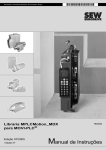
MPLCMotion_MDX and
MPLCMotion_MX Libraries for
MOVI-PLC®
Edition 07/2006
11423412 / EN
FE330000
Manual
SEW-EURODRIVE – Driving the world
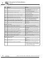
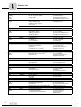
1 Important Notes...................................................................................................... 5
2 Introduction ............................................................................................................ 7
2.1 Areas of application ....................................................................................... 8
2.2 Overview of the MPLCMotion_MDX/MX libraries .......................................... 9
2.3 Overview of additional libraries for the MOVI-PLC® control......................... 11
3 Project Planning and Startup .............................................................................. 12
3.1 Prerequisites ................................................................................................ 12
3.2 Communication times................................................................................... 14
3.3 MOVIDRIVE® B startup ............................................................................... 15
3.4 MOVIAXIS® startup...................................................................................... 19
3.5 MOVIDRIVE® B units and ranges of values ................................................ 20
3.6 MOVIAXIS® units and ranges of values....................................................... 21
4 Description of the Function Modules ................................................................. 22
4.1 General behavior of the function modules ................................................... 22
4.2 State diagram............................................................................................... 27
4.3 MDX/MX_Config directory............................................................................ 29
4.3.1 Function module MC_InitialConfig_MDX/MX .................................... 29
4.3.2 Function module MC_SetSync_MDX/MX ......................................... 32
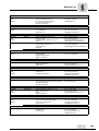
4.4 MDX/MX_InverterParameters directory ....................................................... 34
4.4.1 Function module MC_GetDataprofile4Data_MDX ............................ 34
4.4.2 Function module MC_ReadParameter_MDX/MX ............................. 36
4.4.3 Function module MC_WriteParameter_MDX/MX ............................. 38
4.4.4 Function module MC_SetDynamics_MDX/MX ................................. 40
4.4.5 Function module MC_SetEncoderType_MDX/MX ............................ 42
4.4.6 Function module MC_SetJerk_MDX/MX .......................................... 44
4.4.7 Function module MC_SetLimiter_MDX/MX ...................................... 46
4.4.8 Function module MC_SetHomeParameters_MDX/MX ..................... 49
4.4.9 Function module MC_SetModuloParameters_MDX/MX ................... 51
4.5 MDX/MX_Main directory .............................................................................. 53
4.5.1 Function module MC_ConnectAxis_MDX/MX .................................. 53
4.5.2 Function module MC_ConnectAxisSimulation_MDX/MX ................. 59
4.5.3 Function module MC_Power_MDX/MX ............................................ 62
4.5.4 Function module MC_QuickEnable_MDX/MX .................................. 64
4.5.5 Function module MC_Reset_MDX/MX ............................................. 66
4.6 MDX/MX_SingleAxis directory ..................................................................... 67
4.6.1 Function module MC_MoveVelocity_MDX/MX ................................. 67
4.6.2 Function module MC_MoveAbsolute_MDX/MX ................................ 69
4.6.3 Function module MC_MoveAbsoluteModulo_MDX .......................... 71
4.6.4 Function module MC_MoveRelative_MDX/MX ................................. 74
4.6.5 Function module MC_MoveRelativeModulo_MDX ........................... 76
4.6.6 Function module MC_MoveModulo_MX ........................................... 78
4.6.7 Function module MC_Home_MDX/MX ............................................. 80
4.6.8 Function module MC_AxisStop_MDX/MX and MC_Stop_MDX/MX . 82
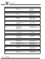
4.7 MDX_SingleAxisSensorless directory.......................................................... 84
4.7.1 Function module MC_MoveVelocitySensorless_MDX ...................... 84
4.7.2 Function module MC_AxisStopSensorless_MDX
and MC_StopSensorless_MDX ........................................................ 86
4.8 MDX/MX_SingleAxisSEW directory ............................................................. 89
4.8.1 Function module MC_MoveTergetSpeed_MDX/MX ......................... 89
4.8.2 Function module MC_MoveTargetPosition_MDX/MX ...................... 92
4.8.3 Function module MC_HomeEnable_MDX/MX .................................. 95
4.8.4 Function module MC_MoveTargetSpeedSensorless_MDX ............. 97
Manual – MPLCMotion_MDX and MPLCMotion_MX Libraries for MOVI-PLC®
3
4.9
MDX/MX_Supplements directory ............................................................... 100
4.9.1 Function module MC_TouchProbe.._MDX/MX ............................... 100
4.9.2 Function module MC_GetInverterInfos_MDX/MX ........................... 103
4.9.3 Function module MC_ReadActualPosition_MDX ........................... 105
4.9.4 Function module MC_ReadAxisError_MDX ................................... 106
4.9.5 Function module MC_ReadStatus_MDX ........................................ 107
4.10 Error ID ...................................................................................................... 109
5 Programming Examples .................................................................................... 111
5.1 Prerequisites .............................................................................................. 111
5.2 Positioning a motor axis ............................................................................. 112
5.3 Speed control of a motor axis with encoder ............................................... 124
5.4 Jog mode of a motor axis without encoder ................................................ 129
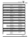
6 Appendix ............................................................................................................. 134
6.1 Overview of the transferred MOVIDRIVE® / MOVIAXIS® actual values .... 134
6.2 CAN identifier ............................................................................................. 135
6.3 MOVIDRIVE® B system variables.............................................................. 137
7 Index .................................................................................................................... 138
4
Manual – MPLCMotion_MDX and MPLCMotion_MX Libraries for MOVI-PLC®
Important Notes
1
1
Important Notes
Documentation
Bus systems
Manual
•
This manual does not replace the detailed operating instructions.
•
The MOVI-PLC® control and the drives it controls may only be installed and
started up by trained personnel observing the applicable accident prevention
regulations, the MOVI-PLC® control manual and the MOVIDRIVE® MDX60B/61B
or MOVIAXIS® MX operating instructions.
•
Read through this manual carefully before you start to install and startup inverters or
servo inverter controlled by the MOVI-PLC® control.
•
This manual assumes that the user has access to and is familiar with the
MOVIDRIVE® and MOVIAXIS® documentation, in particular the MOVIDRIVE®
MDX60B/61B system manual and the MOVIAXIS® system folder.
•
In this manual, cross references are marked with "→". For example, (→ section X.X)
means: Further information can be found in section X.X of this manual.
•
As a prerequisite to fault-free operation and fulfillment of warranty claims, you must
adhere to the information in the documentation.
General safety notes for bus systems:
This communication system allows you to adjust the MOVI-PLC® control, the
MOVIDRIVE® inverter and the MOVIAXIS® servo inverter to your specific application
very accurately. As with all bus systems, there is a danger of invisible, external (as far
as the unit is concerned) modifications to the settings, which give rise to changes in the
unit behavior. This may result in unexpected (not uncontrolled, though) system behavior
when considering this unit.
Manual – MPLCMotion_MDX and MPLCMotion_MX Libraries for MOVI-PLC®
5
Important Notes
1
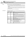
Explanation of
the safety and
warning notes
Observe the safety and warning notes contained in this documentation!
Electrical hazard
Possible consequences: Severe or fatal injuries
Hazard
Possible consequences: Severe or fatal injuries
Hazardous situation
Possible consequences: Slight or minor injuries
Harmful situation
Possible consequences: Damage to the unit and the environment.
Tips and useful information
6
Manual – MPLCMotion_MDX and MPLCMotion_MX Libraries for MOVI-PLC®
Introduction
2
2
Introduction
Content of the
manual
This user manual describes the function modules of the MPLCMotion_MDX and
MPLCMotion_MX libraries as well as their application.
Description
MOVI-PLC® is a programmable logic control designed in accordance with IEC 61131-3.
One feature of the MOVI-PLC® control is, for example, the DHP11B control card.
You can use the MOVI-PLC® control, for example, as the control unit of a machine module. In this way, MOVI-PLC® controls all the drives within the machine module and in
doing so takes off load from the machine control (e.g. machine or system PLC). In
conjunction with a DOP operator terminal and CANopen IOs, MOVI-PLC® can also be
used as a control for entire machines.
The MPLCMotion_MDX and MPLCMotion_MX libraries of the MOVI-PLC® control
described in this manual allow you to program the axis movements of connected
MOVIDRIVE® MDX60B/61B / MOVIAXIS drives simply and centrally.
The control of the MOVITRAC® 07 / B, MOVIMOT® frequency inverter and the
integrated frequency inverter in the MOVIFIT® FC is described in the
"MPLCMotion_MC07 and MPLCMotion_MM libraries for MOVI-PLC®".
For further information about the MPLCProcessdata, refer to the system manual
"MOVI-PLC® programming in the PLC Editor".
Functions
The MPLCMotion_MDX and MPLCMotion_MX libraries provide the following functions
for each connected MOVIDRIVE® MDX60B/61B or MOVIAXIS® drive:
•
Administrative functions
•
Inverter operation (speed specification)
•
Reference travel
•
Positioning
•
etc.
These functions are executed decentrally in the inverters and servo inverters. The
MPLCMotion_MDX and MPLCMotion_MX libraries ensure fast communication with the
inverters and servo inverters and allow you to program the motor axis movements simply and centrally in the MOVI-PLC® control.
Additional
documentation
For simple and effective use of the MPLCMotion_MDX and MPLCMotion_MX libraries,
you should also order the following documentation:
•
System manual "MOVI-PLC® programming in PLC editor"
•
"MOVI-PLC® basic DHP11B control" manual.
•
"MOVIDRIVE® MDX60B/61B" system manual
•
"MOVIAXIS®" system folder
You must follow the instructions and safety notes published in these manuals when
working with the drive system.
Manual – MPLCMotion_MDX and MPLCMotion_MX Libraries for MOVI-PLC®
7
Introduction
Areas of application
2
2.1
Areas of application
The MPLCMotion_MDX and MPLCMotion_MX libraries are suitable for all applications
in which the MOVI-PLC® controls one or more inverters centrally.
Application
examples
Features
8
Typical application examples of the MPLCMotion_MDX and MPLCMotion_MX libraries:
•
Machine modules
•
Small machines
•
System modules
•
Storage and retrieval systems
•
Hoist stations
•
...
The MPLCMotion_MDX and MPLCMotion_MX libraries have the following characteristics:
•
The MOVI-PLCbasic DHP11B control can control up to 12 drives with the aid of the
MPLCMotion_MDX and MPLCMotion_MX libraries. The MOVI-PLC advanced
control can control up to 64 drives.
•
Users do not have to work with communication interfaces. Instead, they can operate
the MOVI-PLC control using only motion and administration commands. Users do
not have to be familiar with system bus communication and only require basic knowledge of the parameter settings of the inverter or servo inverters (e.g. for startup or
setting the system bus address).
•
The system bus enables fast communication between the MOVI-PLC® control and
the inverters / servo inverters.
•
The MPLCMotion_MDX and MPLCMotion_MX libraries contain numerous function
modules. Users can use these modules to program their own applications quickly
and flexibly.
•
PLCopen-compliant commands allow users to familiarize themselves with the program quickly and easily.
Manual – MPLCMotion_MDX and MPLCMotion_MX Libraries for MOVI-PLC®
Introduction
Overview of the MPLCMotion_MDX/MX libraries
2.2
2
Overview of the MPLCMotion_MDX/MX libraries
Required libraries
Install the MPLCMotion_MDX and MPLCMotion_MX libraries in the library manager of
the PLC editor of the MOVITOOLS® MotionStudio software (→ section "Programming
examples").
As a result, the following listed libraries required for the design of components of the
MPLCMotion_MDX and MPLCMotion_MX libraries are automatically installed in the
library manager and for setting the target system (→ "Programming examples" section).
•
MPLCDatatypes
•
MPLCInterface_CAN
•
MPLCInterface_COM
•
MPLCInterface_MoviLink
•
MPLCSystem_ErrorCodes
•
MPLCSystem_MathFunctions
•
MPLCSystem_"MOVI-PLC-Typ"
(e.g. MPLCSystem_DHP11B, according to target system setting)
The MPLCMotion_MDX and MPLCMotion_MX libraries contain the following
function modules, which are divided into several directories according to their function:
MDX/MX_Config
MDX/MX_Config directory:
– MC_InitialConfig_MDX/MX
– MC_SetSync_MDX/MX
MDX/MX_Inverter
Parameters
MDX/MX_InverterParameters directory:
MDX/MX_Main
MDX/MX_Main directory:
–
–
–
–
–
–
–
–
–
–
–
–
–
–
MDX/MX_Single
Axis
MC_GetDataprofile4Data_MDX
MC_ReadParameter_MDX/MX
MC_WriteParameter_MDX/MX
MC_SetDynamics_MDX/MX
MC_SetEncoderType_MDX/MX
MC_SetJerk_MDX/MX
MC_SetLimiter_MDX/MX
MC_SetHomeParameters_MDX/MX
MC_SetModuloParameters_MDX/MX
MC_ConnectAxis_MDX/MX
MC_ConnectAxisSimulation_MDX/MX
MC_Power_MDX/MX
MC_QuickEnable_MDX/MX
MC_Reset_MDX/MX
MDX/MX_SingleAxis directory:
– MC_Home_MDX/MX
– MC_AxisStop_MDX/MX
– MC_Stop_MDX/MX
•
Continuous motion function module:
– MC_MoveVelocity_MDX/MX
Manual – MPLCMotion_MDX and MPLCMotion_MX Libraries for MOVI-PLC®
9
Introduction
Overview of the MPLCMotion_MDX/MX libraries
2
•
Discrete motion function modules:
–
–
–
–
–
MDX_SingleAxis
Sensorless
MC_MoveAbsolute_MDX/MX
MC_MoveAbsoluteModulo_MDX
MC_MoveRelative_MDX/MX
MC_MoveRelativeModulo_MDX
MC_MoveModulo_MX
MDX_SingleAxisSensorless directory:
– MC_StopSensorless_MDX
– MC_AxisStopSensorless_MDX
•
Continuous motion function module:
– MC_MoveVelocitySensorless_MDX
The MC_SingleAxisSensorless directory only exists in the MPLCMotion_MDX
library.
MDX/MX_Single
AxisSEW
MDX/MX_SingleAxisSEW directory:
– MC_HomeEnable_MDX/MX
•
Continuous motion function modules:
– MC_MoveTargetSpeed_MDX/MX
– MC_MoveTargetSpeedSensorless_MDX
•
Discrete motion function modules:
– MC_MoveTargetPosition_MDX/MX
– MC_MoveTargetPositionModulo_MDX/MX
The MC_MoveTargetSpeedSensorless
MPLCMotion_MDX library.
MDX/MX_Supple
ments
function
module
only
exists
in
the
MDX_Supplements directory:
–
–
–
–
–
–
MC_TouchProbe1_MDX/MX
MC_TouchProbe2_MDX/MX
MC_GetInverterInfos_MDX/MX
MC_ReadActualPosition_MDX
MC_ReadAxisError_MDX
MC_ReadStatus_MDX
Note:
You can use the MPLCMotion_MDX und MPLCMotion_MX libraries with all the other libraries for the MOVI-PLC® control at the same time.
However, fault-free operation can only be ensured when you operate all inverters and
servo inverters, which are controlled using the function modules of the
MPLCMotion_MDX and MPLCMotion_MX libraries, on one or more system CAN buses
on which no other manually configured CAN objects (e.g. SCOM Transmit/Receive) are
set up.
10
Manual – MPLCMotion_MDX and MPLCMotion_MX Libraries for MOVI-PLC®
Introduction
Overview of additional libraries for the MOVI-PLC® control
2.3
2
Overview of additional libraries for the MOVI-PLC® control
In addition to the MPLCMotion_MDX and MPLCMotion_MX libraries, you can install a
number of additional libraries in the PLC editor of the MOVITOOLS® MotionStudio software to optimize the control of the drive and frequency inverters provided by SEWEURODRIVE as well as other periphery modules.
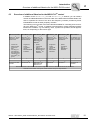
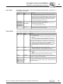
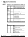
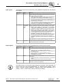
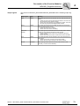
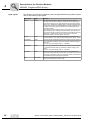
The following is an overview of the basic libraries available for controlling units connected to the MOVI-PLC® control. In addition to these libraries, further application-specific
libraries are available, e.g. for handling, cams, synchronous operation, winder applications, etc. depending on the inverter type.
MPLCProcessdata
®
MPLCMotion_MDX
®
MPLCMotion_MC07
®
MPLCMotion_MX
®
MPLCMotion_MM
®
MOVI-PLC can be
used as a conventional control
MOVI-PLC as
motion control for
MOVIDRIVE® B
MOVI-PLC as
motion control for
MOVITRAC® 07
MOVITRAC® B
MOVIFIT®
MOVI-PLC as
motion control for
MOVIAXIS®
MOVI-PLC as
motion control for
MOVIMOT®
•
•
•
•
•
•
Controls all
SEW inverters
via process
data
For using process data profiles, application
modules or your
own IPOS® programs
↓
•
Single-axis
motion
commands
Use of
MOVIDRIVE® B
interfaces
↓
SEW process data
modules
MOVIDRIVE® B
•
Speed
commands
Use of
MOVITRAC® 07
MOVITRAC® B
MOVIFIT® FC
interfaces
↓
MOVITRAC® 07
MOVITRAC® B
MOVIFIT® FC
•
Single-axis
motion
commands
Use of
MOVIAXIS®
interfaces
↓
MOVIAXIS®
•
MPLCUtilities
For example, connection with CANopen I/O modules
Speed
commands
Use of
MOVIMOT®
interfaces
↓
MOVIMOT®
↓
CANopen I/O
modules
Elements that have to be installed in the control configuration of the PLC editor to be able to use the libraries
Overview of the inverter / unit-specific motion libraries and input / output libraries
Manual – MPLCMotion_MDX and MPLCMotion_MX Libraries for MOVI-PLC®
11
I
3
Project Planning and Startup
Prerequisites
0
3
Project Planning and Startup
This section describes the prerequisites for using the MPLCMotion_MDX and
MPLCMotion_MX libraries and contains important information for project planning and
startup.
3.1
Prerequisites
PC and software
An engineering PC and the MOVITOOLS® MotionStudio software are both required to
program the MOVI-PLC® control using the MPLCMotion_MDX and MPLCMotion_MX libraries. For more information on the PC and software requirements, refer to the "MOVIPLC® programming in PLC editor" system manual.
MOVI-PLC®
The firmware version of the MOVI-PLC® and the version of the Motion library must be
identical. Both versions can be displayed using the "Information & remote control" tool
(open using the context menu of "MOVI-PLC®" in the MOVITOOLS® MotionStudio software). Load the appropriate versions of firmware and Motion library using the "Version
management" tool (open using the context menu of "MOVI-PLC®" in the MOVITOOLS®
MotionStudio software).
For fault-free operation, all function modules (except MC_QuickEnable_MDX/MX function module) of the MPLCMotion_MDX and MPLCMotion_MX libraries must each be
executed in the same task of the MOVI-PLC® (→ "MOVI-PLC® programming in PLC
editor" system manual).
MOVIDRIVE® B
12
•
The MOVI-PLC® control can only be used to control the MOVIDRIVE® MDX60B/61B
inverter from MOVIDRIVE® firmware version 824 854 0.16.
•
If the MOVI-PLC® control is installed in the MOVIDRIVE® MDX61B, at least firmware
version 824 854 0.16 is required even when this MOVIDRIVE® MDX61B is not controlled by the MOVI-PLC® control.
•
The standard version of MOVIDRIVE® MDX60B/61B is sufficient to use the continuous motion function modules (→ section. 2.2) and function modules that position the
motor
axis
(discrete
motion
function
modules,
MC_Home_MDX,
MC_HomeEnable_MDX).
Manual – MPLCMotion_MDX and MPLCMotion_MX Libraries for MOVI-PLC®
I
Project Planning and Startup
Prerequisites
3
0
MOVIAXIS®
The MOVI-PLC® control can only be used to control the MOVIAXIS® servo inverter from
MOVIAXIS® firmware version 1820 880 0.20.
Control topology
You can connect up to 64 of the following inverters to the MOVI-PLC® control via the
system CAN buses (up to 12 with MOVI-PLC® basic):
•
MOVIDRIVE® MDX60B/61B
•
MOVIAXIS®
•
MOVITRAC® 07 / B
•
MOVIMOT® (fieldbus interface CANopen MFO... required)
•
Inverters controlled via the MPLCProcessdata library (e.g. MOVIDRIVE® A)
Note the following prerequisites for MOVI-PLC® basic DHP11B..:
•
Connect a maximum of six inverters to one system CAN bus.
– When connecting up to three inverters to one system CAN bus: Set the baud rate
of the system CAN bus to 500 kbit/s.
– When connecting four to six inverters to one system CAN bus: Set the baud rate
of the system CAN bus to 1000 kBit/s (when the fastest possible data transfer rate
is required).
Important:
The technical characteristics given in this section only apply when no other CAN bus
stations are active on the system CAN bus used to control the inverters / servo inverters.
Do not connect any other CAN bus stations to the system CAN bus on which inverters
are controlled by the libraries listed in "Overview of additional libraries for the MOVIPLC® control".
Manual – MPLCMotion_MDX and MPLCMotion_MX Libraries for MOVI-PLC®
13
I
3
Project Planning and Startup
Communication times
0
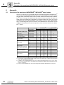
3.2
Communication times
All MOVIDRIVE® MDX60B/61B / MOVIAXIS® units connected to the MOVI-PLC®
control send their current actual values to the MOVI-PLC® control. The cycle time for the
transfer of the actual values is dependent on the data profile that is set in the control configuration for the module parameters of the inverter / servo inverter. Note the update
times of the actual values of MOVIDRIVE® MDX60B/61B and MOVIAXIS® during
project planning.
For a detailed description of the data profiles and the corresponding communication
times, refer to the appendix (→ section 6.1).
MOVIDRIVE® B SSI encoder
Using an SSI encoder slows access to all the parameters by a factor of five. Therefore,
you should avoid using an SSI encoder for MOVIDRIVE® B and use a Hiperface®
encoder instead.
These characteristics affect the response time of the MOVI-PLC® control in conjunction
with the inverters. Take these characteristics into account during project planning.
14
Manual – MPLCMotion_MDX and MPLCMotion_MX Libraries for MOVI-PLC®
Project Planning and Startup
MOVIDRIVE® B startup
I
3
0
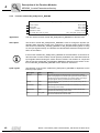
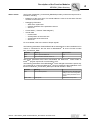
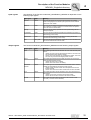
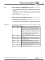
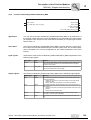
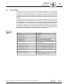
3.3
MOVIDRIVE® B startup
This section describes the startup of the MOVIDRIVE® B inverter. The startup process
must be performed when the drive inverter is to be controlled by the MOVI-PLC® control.
Warning:
Only start up the inverter using the startup assistant described in this section.
The following actions must only be performed by trained personnel for initial startup,
restart or optimization.
•
Manual changes to inverter parameters
•
A direct startup for the inverter using the motor startup assistant
Manual changes could lead to unforeseeable operating states that could cause severe
or fatal injuries to personnel.
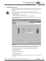
58194AXX
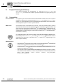
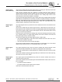
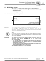
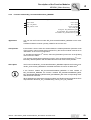
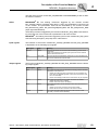
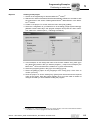
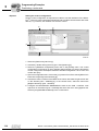
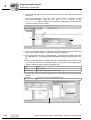
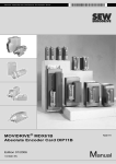
To access the startup assistant [DriveStartup for MOVI-PLC], open the context menu for
the entry [MDX...] in the unit tree of the MOVITOOLS® MotionStudio software.
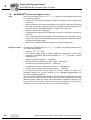
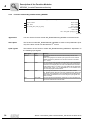
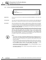
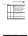
The startup assistant guides you step-by-step through the startup procedure:
1. Load the delivery status
2. Start up the inverter
3. Configure the Shell parameters
4. Download the input values
5. Save the inverter data
The startup assistant detects automatically whether you want to perform initial startup
or a restart.
Manual – MPLCMotion_MDX and MPLCMotion_MX Libraries for MOVI-PLC®
15
3
I
Project Planning and Startup
MOVIDRIVE® B startup
0
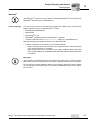
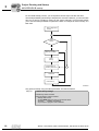
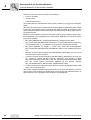
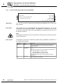
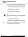
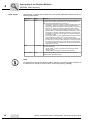
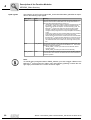
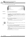
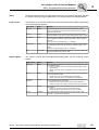
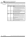
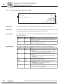
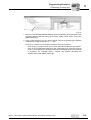
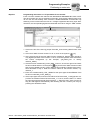
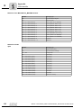
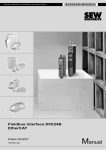
For the initial startup process, you must perform all five steps one after the other.
The startup assistant goes directly to step three for a restart. However, you can start with
step one or two for a restart by clicking on the entries manually. This procedure allows
you to use the startup assistant to optimize the data, for example for motor startup, at a
later date.
Start / Diagnostics
monitor
Initial
startup
YES
Factory settings
“Delivery condition"
NO
Motor
startup
Configuration of
SHELL parameters
Download
Data backup
58225AEN
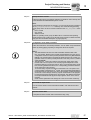
Only perform startup using the startup assistant. Proceed as follows:
Step one
Load the factory settings
The delivery status is loaded.
When the delivery status is loaded:
• Startup data is reset
• All Shell parameters are reset to the default values
• All IPOSplus® variables are deleted
• Any IPOSplus® program code is deleted
16
Manual – MPLCMotion_MDX and MPLCMotion_MX Libraries for MOVI-PLC®
Project Planning and Startup
MOVIDRIVE® B startup
I
3
0
↓
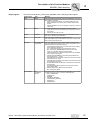
Step two
Startup the drive inverter
Follow the instructions of the startup assistant. For details on motor startup, refer
to the MOVIDRIVE® MDX60B/61B system manual.
Note:
In the operating mode groups V/f and VFC, you can execute function modules of
the MDX_SingleAxisSensorless directory. One of the following operating
mode groups has to be set for function modules in the MDX_SingleAxis directory:
• VFC n-control
• CFC control
• SERVO control
Within an operating mode group, the MOVI-PLC® control sets the operating
mode required for the continuous or discrete motion function modules automatically (see also the detailed description on page page 26).
↓
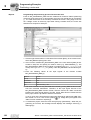
Step three
Configuration of the Shell parameters
Follow the instructions of the startup assistant. You can either accept the default
values by clicking [Apply proposal] or change the values as required.
Notes:
1. The SBus address set here must match the SBus address used at the
MC_ConnectAxis_MDX function module and the address set in the control
configuration of the PLC editor (module parameter of the entry MOVIDRIVE®
MDX B). The set baud rate must match the baud rate set in the control configuration of the PLC editor (module parameter of the entry CAN 1/2, default
value 500 kBaud).
2. The MOVI-PLC® control can read and use the binary inputs of the drive
inverter basic unit or its option in the control program independent of the
parameter settings in the groups P60x or P61x. To prevent the binary inputs
from executing additional functions, the corresponding parameters must be
set to IPOS Input or No Function.
To use the binary outputs of the drive inverter basic unit or its option in the
control program of the MOVI-PLC® control, the corresponding parameters in
the groups P62x or P63x have to be set to IPOS Output. If these parameters
are not set to IPOS Output, the binary outputs will be written in the program,
but the physical output signals will not be changed. The difference between
the output variables and the physical output signal is shown in the control
program.
Some of these parameters are already set to the correct value on delivery.
↓
Step four
Download the input values
You can use this function to load the relevant SHELL user data into the drive
inverter.
↓
Step five
Save the inverter data
A complete set of the inverter data is saved in the file [*.vd0].
Manual – MPLCMotion_MDX and MPLCMotion_MX Libraries for MOVI-PLC®
17
3
I
Project Planning and Startup
MOVIDRIVE® B startup
0
Important:
IPOS® drive
inverter
18
•
During and after startup, parameters in MOVIDRIVE® B that are changed without
using the startup assistant "DriveStartup for MOVI-PLC" must only be performed by
trained personnel.
•
Parameter changes made by a restart with the startup assistant "DriveStartup for
MOVI-PLC" using the function module MC_WriteParameter_MDX or in the Shell of
the MOVIDRIVE® B are not automatically recorded in the MOVI-PLC® control program. They can lead to unforeseeable operating states. The new parameters set in
the inverter are used in the control program after a reset and a restart of MOVI-PLC®.
•
Special parameters that cannot be set using the startup assistant "DriveStartup for
MOVI-PLC" must only be changed by trained personnel. Note that changing some
parameters can lead to unforeseeable operating states.
If you control the drive system using the MPLCMotion_MDX.lib library, users cannot
program the IPOSplus® software in the connected inverters themselves.
Manual – MPLCMotion_MDX and MPLCMotion_MX Libraries for MOVI-PLC®
Project Planning and Startup
MOVIAXIS® startup
I
3
0
3.4
MOVIAXIS® startup
Startup of the MOVIAXIS® servo inverter is described in the "MOVIAXIS® MX multi-axis
servo inverter" operating instructions.
•
Ensure the unit is in the delivery state at the beginning of the startup procedure.
To do this, set the P9727.3 Delivery status d1 parameter to the value "1". If the parameters set in the motor startup are not reset to the default values, you can also set
the P9727.4 Factory setting d2 parameter to the value "1".
•
The transmission rate set at the power supply module (switch S1 to S4) and the basic
address for the system bus (MOVIAXIS® signal bus) must correspond with the module parameters set in the control configuration. The basic address corresponds to the
SBus address of the axis module directly to the right of the power supply module.
The axis modules to the right are automatically assigned increasing addresses that
must be set correspondingly in the control configuration for the control of the motor
axes ( "MOVI-PLC® programming in the PLC editor" system manual).
Please read the following warning notes:
•
No manual settings are required in the PDO editor for using the function modules
from the MPLCMotion_MX library. Function module MC_ConnectAxis_MX configures all the required settings automatically. The following settings that are described
may be made in the PDO editor for the use of special functions.
•
The control word 0 of the MOVIAXIS® servo inverter is used by the MOVI-PLC® control and must not be changed. The control word 1 of the MOVIAXIS® servo inverter
is connected by the function module MC_ConnectAxis_MX with the binary inputs.
The default setting of the bits of the control word 1 is "No function". In this setting, the
binary inputs of the MOVIAXIS® can be freely used in the program of the MOVI-PLC®
control without additional functions. They appear in the control configuration of the
MOVI-PLC® control. In addition, you can assign the individual bits of control word 1
in the parameter tree or in the PDO editor with special functions (e.g. CW limit
switch).
•
Important reference parameters are set using the function module
MC_SetHomeParameters_MX. You can set additional reference parameters in the
parameter tree (FCB12) or using the function module MC_WriteParameter_MX (→
section "Function module MC_SetHomeParameters_MX").
•
In addition, ongoing activities must only be performed by trained personnel as manual changes can lead to unforeseeable operating states that can cause death or
serious injury to personnel.
Manual – MPLCMotion_MDX and MPLCMotion_MX Libraries for MOVI-PLC®
19
I
3
Project Planning and Startup
MOVIDRIVE® B units and ranges of values
0
3.5
MOVIDRIVE® B units and ranges of values
Units
The function modules of the MPLCMotion_MDX library use the following units for their
input and output signals:
•
Positions in increments [incr] (4096 increments correspond to a 360° rotation of the
motor axis)
•
Modulo positioning in modulo increments [incr] (216 modulo increments correspond
to a motor axis rotation of 360). The number of complete rotations is specified in the
high word and the target angle between 0° and 360° in the low word.
•
Speeds in revolutions / minute [rpm]
•
Accelerations as ramp times in milliseconds to achieve a speed [ms] changed by
3000 rpm.
The Acceleration input signal specifies the acceleration for increasing the kinetic
energy in the motor. The Deceleration input signal specifies the braking deceleration
for reducing the kinetic energy.
•
Ranges of values
Jerk as time in milliseconds for the duration of the torque build-up [ms]
For the function modules of the MPLCMotion_MDX library, the following maximum ranges of values are permitted:
•
Positions: -(231) ... 231 [incr]
•
The maximum setting range of modulo positioning is dependent on the modulo
numerator, denominator and encoder resolution: 0 ... 231 / (numerator encoder
resolution) [incr].
•
Speeds for positioning tasks: 0 ... 6000 [rpm]
•
Speeds for speed-controlled travel tasks: -6000 ... 6000 [rpm]
•
Accelerations for positioning tasks: 10 ... 20000 [ms]
•
Accelerations for speed-controlled travel tasks: 0 ... 2000000 [ms]
•
Jerk (not used for speed-controlled travel tasks): 5 ... 2000 [ms]
If the values are outside of these ranges, the function modules will output error
messages (except the function modules in the MDX/MX_SingleAxisSEW and
MC_SetJerk_MDX/MX directory).
The drive inverter adjusts the travel tasks to these limit values automatically depending
on the motor connected and the limit values set in the inverter parameters (e.g. P302
Maximum speed). These limit values can be lower than the maximum values that can
be set in the function modules. In this case, the function modules do not output error
messages. As a result, lag errors can occur during positioning tasks.
20
Manual – MPLCMotion_MDX and MPLCMotion_MX Libraries for MOVI-PLC®
Project Planning and Startup
MOVIAXIS® units and ranges of values
I
3
0
3.6
MOVIAXIS® units and ranges of values
Units
The user-defined units for the following sizes can be set as required for the MOVIAXIS®
servo inverter (→ "MOVIAXIS® MX multi-axis servo inverter"):
•
Travel distance
•
Velocity
•
Acceleration
•
Torque
The input and output signals of the function modules of the MPLCMotion_MX library
correspond to the set user-defined units.
Ranges of values
The maximum permitted ranges of values for the function modules of the
MPLCMotion_MX library depend on the set user-defined units (→ "MOVIAXIS® MX
multi-axis servo inverter" operating instructions).
MOVIAXIS® adjusts the travel tasks to these limit values automatically depending on the
motor connected and the limit values set in the servo inverter parameters.
Manual – MPLCMotion_MDX and MPLCMotion_MX Libraries for MOVI-PLC®
21
Description of the Function Modules
General behavior of the function modules
4
4
Description of the Function Modules
This section describes the functions and behavior of the function modules of the
MPLCMotion_MDX and MPLCMotion_MX libraries.
4.1
General behavior of the function modules
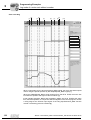
This section describes the basic functionality of the inputs and outputs of the function
modules and other general features of the MOVI-PLC® control and the inverters. For
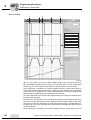
specific examples of the interaction and sequence of several function modules, including time diagrams, refer to section 5, "Programming examples".
There are two types of function modules. They are divided into two activation types.
Input signal
Enable
•
Function modules that are activated by the input signal Enable.
•
Function modules that are activated by the input signal Execute.
Function modules that are activated by the input signal Enable typically perform cyclical
actions (e.g. MC_ReadActualPosition_MDX).
•
When the input signal Enable = TRUE,
– The function module is active.
– The function module recalculates the output signals in each cycle.
•
When the input signal Enable = FALSE,
– The function module does not recalculate the output signals.
– All the output signals remain at the value that was last calculated. (Exception:
Done, Busy and Error are reset to FALSE.)
Therefore, you must verify the value of the output signals by setting the output signal
Done = TRUE.
The Enable input of the function module MC_ConnectAxis_MDX/MX and
MC_ConnectAxisSimulation_MDX/MX differs from the behavior described here. For details, please refer to the description of this function module.
Input signal
Execute
Function modules that are activated by the input signal Execute typically perform an
action once (e.g. MC_ReadParameter_MDX/MX).
A positive edge change at the Execute input starts the action.
The output signals remain in effect until the input signal Execute is reset to FALSE (falling edge) or the function module is cancelled. However, if the input signal Execute is
reset to FALSE before the action is completed, the output signals remain in effect for at
least one more control cycle after the action has been concluded.
If a rising edge occurs at the Execute input, the values of the input signals are adopted
for the action. Changing the input signals during the action has no effect. Another rising
edge signal is required at the Execute input to adopt the modified values.
22
Manual – MPLCMotion_MDX and MPLCMotion_MX Libraries for MOVI-PLC®
Description of the Function Modules
General behavior of the function modules
Output signal
Done/InVelocity
4
The function module sets the output signal Done or InVelocity to TRUE once the action
of the function module has been executed successfully.
Some function modules maps the conditions In Position (discrete motion tasks) or
Speed reached (continuous motion tasks) of the drive inverter to the output signal Done.
These function modules check these conditions until a falling edge occurs at the
Execute input or the function module is cancelled.
As long as the input signal Execute is set to TRUE, the function module resets the output
signal Done to FALSE when the condition In Position or Speed reached is no longer fulfilled. The output signal Done is set to TRUE when the condition is fulfilled again. Consequently, when the input signal Execute is set to TRUE, the output signal Done can
change between TRUE and FALSE several times.
Output signal
Active
The output signal Active only exists for function modules that control a movement of the
motor axis.
The function module sets the output signal Active to TRUE when the motor axis controlled by the function module turns to reach its target (target position and target speed).
The function module usually sets the output signal Active to TRUE shortly after a rising
edge occurs at the input Execute.
If the motor axis is prevented from rotating due to the terminal assignment at the inverter
(e.g. controller inhibit or no output stage enable), the function module is executed, but
the output signal Active is reset to FALSE.
The function module sets the output signal Active to TRUE, when
•
The terminal assignment on the drive inverter enables the motor axis to turn when
the function module is executed
•
The motor axis moves until it reaches the target
The function module resets the output signal Active to FALSE when one of the output
signals Done,InVelocity, Error or CommandAborted is set to TRUE.
Output signal
Busy
The output signal Busy only exists for function modules that require several control
cycles for execution and that do not control any movements of the motor axis.
The function module sets the output signal Busy to TRUE as long as the function module
is executed.
The function module resets the output signal Busy to FALSE when one of the output signals Done or Error is set to TRUE.
Output signal
Command
Aborted
The output signal CommandAborted only exists for function modules that control a
movement of the motor axis.
The function module sets the output signal CommandAborted to TRUE, when its execution is cancelled
•
by another function module or
•
by another instance of the same function module
when both control the same motor axis.
Manual – MPLCMotion_MDX and MPLCMotion_MX Libraries for MOVI-PLC®
23
4
Description of the Function Modules
General behavior of the function modules
Otherwise, the active function module is cancelled for:
•
DC 24 V operation
•
Inverter errors
•
Communication errors
This means that the cancelled task of the function module is no longer executed afterwards.
When the cancelled function module sets the output signal CommandAborted to TRUE,
it resets the output signals Done or InVelocity and Active to FALSE. The function module
resets the output signal CommandAborted to FALSE by setting a falling edge at the input signal Execute.
Motion function modules (continuous / discrete motion function modules and the function modules MC_Home_MDX/MX, MC_HomeEnable_MDX/MX) can cancel the following function modules:
•
MC_Stop_MDX/MX, MC_AxisStop_MDX/MX, MC_StopSensorless_MDX
•
MC_ConnectAxis_MDX/MX (when the MOVI-PLC® control detects an inverter error,
communication error or 24 V operation of the inverter in this function module).
•
MC_Power_MDX/MX for Enable = FALSE (only when MC_Home_MDX/MX,
MC_HomeEnable_MDX/MX and PowerOffMode = MDX_CTRL_INHIBIT are executed)
•
Discrete motion function modules of the MPLCMotion_MDX library can only cancel
discrete motion function modules.
•
Continuous motion function modules of the MPLCMotion_MDX library can only cancel continuous motion function modules. Exception: The function modules
MC_MoveVelocitySensorless_MDX and MC_MoveTargetSpeedSensorless_MDX
can also cancel braking movements triggered by the function modules
MC_AxisStopSensorless_MDX and MC_StopSensorless_MDX.
•
Continuous motion and discrete motion function modules of the MPLCMotion_MX
library can cancel each other.
The function module resets the output signal Done to FALSE on cancellation, even if the
goal of the function module has already been achieved and the specified position or
speed window of the cancelled function module is still maintained.
24
Manual – MPLCMotion_MDX and MPLCMotion_MX Libraries for MOVI-PLC®
Description of the Function Modules
General behavior of the function modules
Output signal
Error
4
If an error occurs in the MOVI-PLC control during the execution of a function module,
the function module sets the output signal Error to TRUE. In this case, the respective
error is displayed at the output signal ErrorID.
Errors in the inverter / servo inverter do not cause the output signal Error to be set, but
are detected in the MC_ConnectAxis_MDX/MX function module and cause the cancellation of the motion function module.
Response to controller inhibit, no
enable, safe stop,
CW stop, CCW
stop or hold control.
When one or more of the following conditions apply, the function module that is currently
active
interrupts
the
active
travel
task
(DISCRETE_MOTION,
CONTINUOUS_MOTION, HOMING) of the motor axis:
•
Controller inhibit (terminal or MC_Power_MDX/MX)
•
No enable (terminal or MC_Power_MDX/MX)
•
Safe stop (terminal)
•
CW stop ( terminal)
•
CCW Stop (terminal)
•
Hold control (terminal)
However, the function module does not cancel the travel task. The target position previously set and the setpoint speed are retained.
When the active travel task is interrupted, the function module
•
Resets the output signal Active to FALSE
•
Does not set the output signal CommandAborted to TRUE
The interruption does not lead to an error at the function module.
As soon as the stated conditions no longer apply, the function module continues the interrupted travel task.
The motion function module is interrupted from the start if the stated conditions are
present at the start of the actual execution. It is executed when the conditions that led
to the interruption are no longer present.
If the action of a motion function module is to be cancelled in the interrupted state and
no additional motion command is to be directly connected, one of the function modules
MC_Stop_MDX/MX, MC_AxisStop_MDX/MX or MC_StopSensorless_MDX/MX must
be executed. This can also occur when the axis is in the "controller inhibit", "no enable",
"safe stop" or "hold control" state.
The electrical rotating field is immediately switched off when setting the controller
inhibit or safe stop. At the same time, the motor brake is applied (independent of the
activation of the brake function in the drive parameters) so that the drive is decelerated
mechanically. Accordingly, drives without motor brakes are free running and coast to a
halt or can be accelerated by external forces.
The drive is decelerated electronically when the enable is revoked or when the CW /
CCW stop or hold control is activated. Axes without encoders under 15 rpm show a
very small maximum torque so that braking to standstill without applying the brake is
only possible with small external forces. For an existing motor brake and activated braking function (P730 for MOVIDRIVE® B; index 8584.0 brake function and index 9833.1
brake type not the same, "no brake", for MOVIAXIS®), the motor brake is applied after
the brake process for MOVIDRIVE® B shortly before reaching standstill and when the
motor standstill is detected for MOVIAXIS®. Accordingly, drives without motor brakes or
with a deactivated brake function are free running after the electronic brake application
and can be accelerated by external forces.
Manual – MPLCMotion_MDX and MPLCMotion_MX Libraries for MOVI-PLC®
25
Description of the Function Modules
General behavior of the function modules
4
If a motor axis that was in position control mode once positioning had been completed
at the time of the interruption and is moved out of its position by free-running and external forces, the axis returns to the last controlled target position after the interruption.
When a braking movement triggered by one of the function modules
MC_Stop_MDX/MX,
MC_AxisStop_MDX/MX,
MC_StopSensorless_MDX
or
MC_AxisStopSensorless_MDX is interrupted by one of the executed conditions and the
axis is not yet at a standstill at the end of the interruption, then the brake operation is
continued after the interruption.
Exception:
The reference travel triggered by the function module MC_HomeMDX/MX or
MC_HomeEnable_MDX/MX is cancelled by setting the controller inhibit. At the same
time, the function module MC_Home_MDX/MX or MC_HomeEnable_MDX/MX sets the
output signal CommandAborted to TRUE.
The reference travel is only interrupted when the enable, CW / CCW stop, hold control
or triggering of the safety stop enable is revoked. After the interruption, the motor continues the reference travel.
Behavior in 24 V
operation
When 24-V operation is activated, the function module that currently controls the movement of the motor axis cancels the travel task. The function module sets the output signal CommandAborted to TRUE. As soon as the axis is at a standstill, the STANDSTILL
state is reached (output signal PLCopenState of the function module
MC_ConnectAxis_MDX, Section "State diagram") .
Changing discrete-motion /
continuous
motion for
MOVIDRIVE® B
The MOVIDRIVE® inverter implements motion function blocks of the type
CONTINUOUS_MOTION in one of the following operating modes:
•
VFC+n control
•
CFC control
•
SERVO control
The MOVIDRIVE® B implements motion function blocks
DISCRETE_MOTION in one of the following operating modes:
•
VFC+n control + IPOS® positioning
•
CFC control + IPOS® positioning
•
SERVO control + IPOS® positioning
of
the
type
The MOVIDRIVE® B does not allow an on-the-fly changeover (that is, without a controller inhibit) in all operating modes. However, standard behavior for all operating modes
is required.
Therefore, changeover is not possible when the motor axis is rotating. In this case, the
respective error message is output at the function module.
Changing discrete-motion /
continuous
motion for
MOVIAXIS®
26
The MPLCMotion_MX library supports the switch between DISCRETE_MOTION and
CONTINUOUS_MOTION function modules.
Manual – MPLCMotion_MDX and MPLCMotion_MX Libraries for MOVI-PLC®
Description of the Function Modules
State diagram
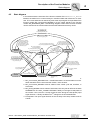
4.2
4
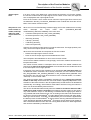
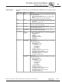
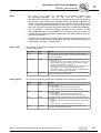
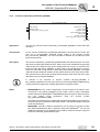
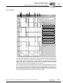
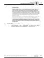
State diagram
In accordance with the execution of the function modules of the MPLCMotion_MDX/MX
libraries, the MOVI-PLC® control is always in a defined state with reference to a motor
axis. The current state can be read at any time at the output signal PLCopenState of the
function module MC_ConnectAxis_MDX/MX or at the output signals of the function
module MC_ReadStatus_MDX. The following diagram shows which function modules
can be executed in the various states and the state transitions that they cause.
MC_MoveAbsolute_MX
MC_MoveModulo_MX
MC_MoveRelative_MX
MC_MoveTargetPosition_MX
MC_MoveVelocity_MX
MC_MoveTargetSpeed_MX
MC_MoveAbsolute_MDX/MX
MC_MoveAbsoluteModulo_MDX
MC_MoveRelative_MDX/MX
MC_MoveRelativeModulo_MDX
MC_MoveTargetPosition_MDX/MX
MC_MoveModulo_MX
4)
MC_MoveVelocitySensorless_MDX
4)
MC_MoveTargetSpeedSensorless_MDX
4)
MC_AxisStop_MDX/MX
4)
MC_Stop_MDX/MX
4)
MC_AxisStopSensorless_MDX
4)
MC_StopSensorless_MDX
DISCRETE_
MOTION
MC_Axi
sSto
MC_Sto p_MDX/MX
p_MDX
/MX
Drive
Error
MC_AxisStop_MDX/MX
MC_Stop_MDX/MX
6)
6) /MX
X X
/M MD
DX lo_
_M odu
ion M
sit ion
Po it
et os
rg tP
Ta rge
ve a
ne o veT
Do C_MMo
M C_
M
MC_MoveAbsolute_MDX/MX
MC_MoveAbsoluteModulo_MDX
MC_MoveRelative_MDX/MX
MC_MoveRelativeModulo_MDX
MC_MoveTargetPosition_MDX/MX
MC_MoveModulo_MX
r
rro
E
ive
DX/MX
sStop_M
MC_Axi p_MDX/MX
to
DX
MC_S
sorless_M
DX
sStopSen
MC_Axi pSensorless_M
MC_Sto
STOPPING
Drive
Error
HOMING
MC_Home_MDX/MX
MC_HomeEnable_MDX/MX
CONTINUOUS_
MOTION
Drive
Error
Done4)
6)
X
ERRORSTOP
Drive
Error
MC_Reset_MDX/MX
Dr
Done
6)
MC_HomeEnable_MDX/MX
MC_MoveVelocity_MDX/MX
MC_MoveTargetSpeed_MDX/MX
MC_MoveVelocitySensorless_MDX
MC_MoveTargetSpeedSensorless_MDX
3)
/M ss
DX le
M sor
_
n
d
e
ee dS
Sp ee
et
p
g
S
ar et
eT rg
ov Ta
M ve
_
C Mo
M
C_
M
STANDSTILL5)
MC_ConnectAxis
_MDX/MX.Done2)
_M
6)
DX
MC_MoveVelocity_MDX/MX
MC_MoveTargetSpeed_MDX/MX
MC_MoveVelocitySensorless_MDX
MC_MoveTargetSpeedSensorless_MDX
All States
MC_ConnectAxis_MDX/MX
Done=FALSE1)
NOT_CONNECTED
= TRUE
58197BXX
1. MC_ConnectAxis_MDX/MX.Done = FALSE when there is a communication error between the MOVI-PLC® control and the inverter / servo inverter.
2. MC_ConnectAxis_MDX/MX must be called in each control cycle and, therefore, in
each state.
3. MC_Reset_MDX/MX can be called in each state, but it only has an effect in the state
ERRORSTOP. The NOT_CONNECTED state is briefly run during the reset phase of
the inverter / servo inverter. If a stop module is active during the reset phase (input
signal Execute = TRUE), the MOVI-PLC® changes to the STOPPING state.
4. Prerequisite: The input signal Execute of the currently active stop module must be
FALSE.
Manual – MPLCMotion_MDX and MPLCMotion_MX Libraries for MOVI-PLC®
27
4
Description of the Function Modules
State diagram
5. The STANDSTILL state is adopted when the minimum speed (15 rpm) is not reached
or the target position window is reached. Possible acceleration caused by external
forces must not lead to changes to the PLCopenState. If a stop module is activated
(rising edge of the input signal Execute) in the STANDSTILL state, the MOVI-PLC®
control changes to the STOPPING state.
The STANDSTILL state is also adopted for MOVIDRIVE® B directly after the reset
procedure when a limit switch error has occurred although the motor axis still attempts to clear the limit switch.
In this case, there is no automatic clearing movement for MOVIAXIS®. A separate
travel task is required in order to move clear.
6. The falling edge of the input signal Enable and function module is not cancelled.
28
Manual – MPLCMotion_MDX and MPLCMotion_MX Libraries for MOVI-PLC®
Description of the Function Modules
MDX/MX_Config directory
4.3
4
MDX/MX_Config directory
The MDX/MX_Config directory covers function modules that enable the configuration
of special functions for controlling a MOVIDRIVE® B / MOVIAXIS®. The function modules in this directory are not required for performing motion tasks without using these
special functions.
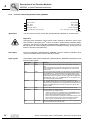
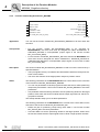
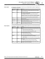
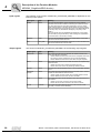
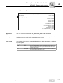
4.3.1
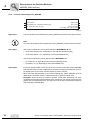
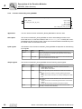
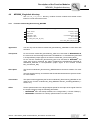
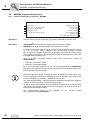
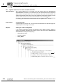
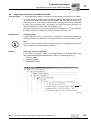
Function module MC_InitialConfig_MDX/MX
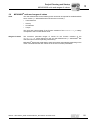
MC_INITIALCONFIG_MDX
Execute : BOOL
Node : CAN_NODE
SBUS_Address : UINT
UseMoveAbsoluteWithoutReference : BOOL
Done : BOOL
Error : BOOL
ErrorID : DWORD
UseExternalCommunicationTask : BOOL
SendSource : MC_PDO_SENDSOURCE_MDX
SendID : MC_PDO_ID_MDX
SendCycleTime : UINT
SendOffset : UINT
ReceivePDO1 : MC_PDO_ID_MDX
ReceivePDO2 : MC_PDO_ID_MDX
ReceivePDO3 : MC_PDO_ID_MDX
ReceivePDO4 : MC_PDO_ID_MDX
59362AXX
Application
You can use the function module MC_InitialConfig_MDX/MX on all motor axes.
Prerequisites
The
function
module
MC_ConnectAxis_MDX/MX
or
MC_ConnextAxisSimulation_MDX/MX , in reference to the same motor axis, must not
yet
have
been
executed
when
executing
the
function
module
MC_InitialConfig_MDX/MX.
Description
Special communication features and functions of the inverter / servo inverter can be activated using the function module MC_InitialConfig_MDX/MX. Execution of the function
module MC_InitialConfig_MDX/MX is not required for using the function modules from
the MPLCMotion_MDX/MX library.
Notes:
•
You must execute the function module MC_InitialConfig_MDX/MX only once for
each motor axis.
•
The inputs SendSource to ReceivePDO4 are only available for function module
MC_InitialConfig_MDX for MOVIDRIVE® B.
If the function module MC_InitialConfig_MDX is executed with the input signal UseMoveAbsoluteWithoutReference = TRUE, unexpected movements of the drive can occur when positioning for unreferenced axes.
Manual – MPLCMotion_MDX and MPLCMotion_MX Libraries for MOVI-PLC®
29
Description of the Function Modules
MDX/MX_Config directory
4
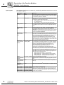
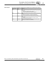
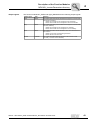
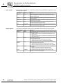
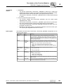
Input signals
30
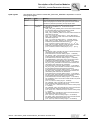
The behavior of the function module MC_InitialConfig_MDX/MX is dependent on the following input signals:
Input signal
Type
Meaning
Execute
BOOL
The input signal Execute starts the task of the function module.
If a rising edge occurs at the input signal, the other input signals
of the function module are adopted.
Node
CAN_NODE
The input signal Node is used to specify the CAN bus node of
the MOVI-PLC® that is connected to the inverter / servo inverter
to which the configuration settings refer.
• SBUS_NODE_1: CAN 1 (connector X33 for DHxx1B; X26
for compact control)
• SBUS_NODE_2: CAN 2 (connector X32 for DHxx1B)
SBUS_Address
UINT
The input signal SBUS_Address is used to specify the system
bus address of the inverter to which the configuration settings
refer.
UseMoveAbsoluteWithoutReference
BOOL
If this input signal is set to TRUE,, the function modules
MC_MoveAbsolute_MDX and MC_MoveAbsoluteModulo_MDX
are executed without the drive inverter being referenced.
Important: Unexpected drive movements can occur for unreferenced axes. The input signal UseMoveAbsoluteWithoutReference is not used for MOVIAXIS®.
UseExternalCommunicationTask
BOOL
The communication between the inverter / servo inverter and
MOVI-PLC® is initialized and executed as standard via the function module MC_ConnectAxis_MDX/MX. To do this, assign the
input signal UseExternalCommunicationTask to FALSE.
If the input signal UseExternalCommunicationTask is set to
TRUE, the inverter communication does not occur via the function module MC_ConnectAxis_MDX/MX but via a function module in an external task (reserved function).
SendSource
(Only for MOVIDRIVE B)
MC_PDO_SENDS
OURCE_MDX
An additional inverter send object can be created on the system
bus independent of the data profile set in the system configuration via the input signal SendSource. The function is reserved
for use in conjunction with the technology libraries (e.g.
MPLCTecGearMotion_MDX/MX) that can read up to four
receive objects (input signals ReceivePDO..).
If the input is not assigned or is assigned with the value
MDX_SEND_OFF, no additional send object is created. Otherwise the input signals SendID, SendCycleTime and SendOffset
are evaluated for the parameter settings of the send object. The
following process values of the MOVIDRIVE® B can be sent via
the additional send object for the corresponding assignment of
the input signal via the system bus:
• MDX_SEND_OFF (default) → No send object
• MDX_SEND_X15 → Actual position X15 motor encoder
• MDX_SEND_X14 → Actual position X14 external encoder
• MDX_SEND_SSI → Actual position X62 SSI encoder
SendID
(Only for MOVIDRIVE B)
MC_PDO_ID_MDX
ID of the MOVIDRIVE B-send object
(Default value 129, all values in MC_PDO_ID_MDX are possible)
SendCycleTime
(Only for MOVIDRIVE B)
UINT
Cycle time of the MOVIDRIVE® B send object in ms (default
value 1)
SendOffset
(Only for MOVIDRIVE B)
UINT
Offset of the MOVIDRIVE® B send object in ms (default value 0)
ReceivePDO1
MC_PDO_ID_MDX
ReceivePDO2
MC_PDO_ID_MDX
ReceivePDO3
MC_PDO_ID_MDX
ReceivePDO4
MC_PDO_ID_MDX
Only available for MOVIDRIVE B.
ID of the respective receive object. This must correspond with
the ID of the required send object (input signal SendID of the
instance of MC_InitialConfig_MDX that refers to the transmitting
inverter / servo inverter).
Manual – MPLCMotion_MDX and MPLCMotion_MX Libraries for MOVI-PLC®
Description of the Function Modules
MDX/MX_Config directory
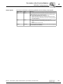
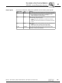
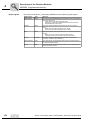
Output signals
4
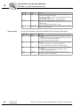
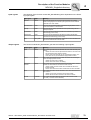
The function module MC_InitialConfig_MDX/MX has the following output signals:
Output signal
Type
Meaning
Done
BOOL
The output signal Done shows whether the function module was correctly executed. You can use the output signal Done directly as the
input signal Enable for the function module
MC_ConnectAxis_MDX/MX of the same motor axis.
• TRUE: The function module MC_Initial was correctly executed.
• FALSE: The function module MC_Initial was incorrectly executed
or not executed at all.
Error
BOOL
The output signal Error shows whether an error occurred.
• TRUE: An error has occurred during the execution of the function
module.
• FALSE: No error has occurred.
ErrorID
DWORD
The output signal ErrorID displays the error code of the occurring error
(→ see Section "Error Identifier").
Manual – MPLCMotion_MDX and MPLCMotion_MX Libraries for MOVI-PLC®
31
Description of the Function Modules
MDX/MX_Config directory
4
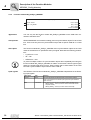
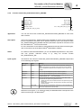
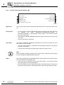
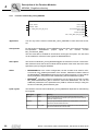
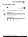
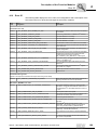
4.3.2
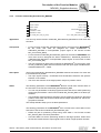
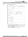
Function module MC_SetSync_MDX/MX
MC_SetSync_MDX
Execute : BOOL
Done : BOOL
Node : CAN_MODE
Busy : BOOL
Error : BOOL
ErrorID : DWORD
58161AXX
Application
You can only use the function module MC_SetSync_MDX/MX on the CAN lines connected to the MOVI-PLC®.
Prerequisites
SEW-EURODRIVE recommends creating just one synchronization object for each CAN
line. There must only be one synchronization object with a specific CAN ID on a CAN
line.
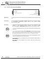
Description
The function module MC_SetSync_MDX/MX sets a synchronization object on the CAN
nodes of the MOVI-PLC® specified at the input signal Node with the following parameters:
•
CycleTime = 5 ms
•
ID = 128
•
OffsetTime = 2ms
To prevent multiple creation of synchronization objects when repeatedly executing the
function module MC_SetSync_MDX/MX in relation to the same CAN line (input signal
Node), the output signal Error is set to TRUE. Ensure that no other station on the CAN
bus sets a synchronization object with the same CAN ID.
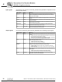
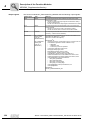
Input signals
32
The behavior of the function module MC_SetSync_MDX/MX is dependent on the following input signals:
Input signal
Type
Meaning
Execute
BOOL
The input signal Execute starts the task of the function module.
When a rising edge occurs at this input signal, the synchronization
object is set up.
Node
CAN-NODE
CAN nodes on which the synchronization object should be set up.
• SBUS_NODE_1: CAN 1 (connector X33 for DHP11B; X26 for
compact control)
• SBUS_NODE_2: CAN 2 (connector X32 for DHP11B)
Manual – MPLCMotion_MDX and MPLCMotion_MX Libraries for MOVI-PLC®
Description of the Function Modules
MDX/MX_Config directory
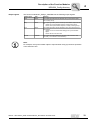
Output signals
4
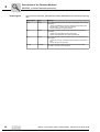
The function module MC_SetSync_MDX/MX has the following output signals:
Output signal
Type
Meaning
Done
BOOL
The output signal Done shows whether the synchronization object
was correctly set up.
Busy
BOOL
The output signal Busy shows that the synchronization object was set
up.
• TRUE: The synchronization object is currently being set up.
• FALSE: The synchronization object is currently not being set up.
Error
BOOL
The output signal Error shows whether an error occurred in the function module.
• TRUE: An error occurred while setting up the synchronization
object.
• FALSE: No error has occurred.
ErrorID
DWORD
The output signal ErrorID displays the error code of the error that
occurred (→ see Section "Error identifier").
Note:
For example, the synchronization object is required when using synchronous operation
or the electronic cam.
Manual – MPLCMotion_MDX and MPLCMotion_MX Libraries for MOVI-PLC®
33
Description of the Function Modules
MDX/MX_InverterParameters directory
4
4.4
MDX/MX_InverterParameters directory
The MDX/MX_InverterParameters directory contains function modules required to
write and read parameters of the MOVIDRIVE® inverter.
4.4.1
Function module MC_GetDataprofile4Data_MDX
MC_GetDataprofile4Data_MDX
Enable : BOOL
ContentData1 : MC_Dataprofile4Data_MDX
ContentData2 : MC_Dataprofile4Data_MDX
ContentData3 : MC_Dataprofile4Data_MDX
ContentData4 : MC_Dataprofile4Data_MDX
Axis : AXIS_REF (VAR_IN_OUT)
Done : BOOL
Busy : BOOL
Error : BOOL
ErrorID : DWORD
Data1 : DINT
Data2 : DINT
Data3 : DINT
Data4 : DINT
Axis : AXIS_REF (VAR_IN_OUT)
59364AXX
Application
You can use the function module MC_GetDataprofile4Data_MDX on all motor axes.
Prerequisites
The data profile number 4 must be set in the module parameters of the MOVIDRIVE® B
in the control configuration so that the function module can be executed (→ Appendix
"Overview of MOVIDRIVE® B / MOVIAXIS® actual values transferred".
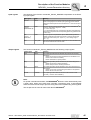
Description
The setpoint speed, actual speed and current motor position of the selected encoder at
the MOVIDRIVE® B are transferred to the MOVI-PLC® for the set data profile 4 and are
available at the output signal InverterData of the function module
MC_ConnectAxis_MDX.
You can also select four MOVIDRIVE® B actual values for the set data profile 4 using
the function module MC_GetDataprofile4Data_MDX that are cyclically transferred to the
MOVI-PLC®. These four actual values are available at the output signals Data1 to
Data4.
34
Manual – MPLCMotion_MDX and MPLCMotion_MX Libraries for MOVI-PLC®
Description of the Function Modules
MDX/MX_InverterParameters directory
Input signals
The behavior of the function module MC_GetDataprofile4Data_MDX is dependent on
the following input signals.
Input signal
Type
Meaning
Enable
BOOL
The input signal Enable is used to activate the function module
MC_GetDataprofile4Data_MDX/MX. The function module is only
executed when the input signal Enable is set to TRUE. The values
of other input signals of the function module are only read when a
rising edge occurs at the input signal Enable. The actual values
(output signals Data1 to Data4) are only transferred when the
input signal Enable remains set to TRUE.
ContentData1
ContentData2
ContentData3
MC_DATAPROF4
DATA_MDX
ContentData4
Axis
Output signals
4
Input signals ContentData1 to ContentData4
are used to determine which MOVIDRIVE® B actual values are
transferred in each double word.
(→ MC_DATAPROFILE4DATA_MDX)
The input signal Axis specifies the motor axis on which the actions
of the function module are to be executed.
AXIS_REF
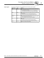
The function module MC_GetDataprofile4Data_MDX has the following output signals:
Output signal
Type
Meaning
Done
BOOL
The output signal Done shows whether the transferred MOVIDRIVE®
B actual values are valid.
• TRUE: Initialization is complete and the transferred actual values
are valid.
• FALSE: The connection between MOVIDRIVE® B and MOVIPLC® is interrupted and the transferred actual values are invalid.
For example, a termination of the connection can occur during the
reset phase of MOVIDRIVE® B or when there is a fault on the system
bus. In this case, the motor axis is in the NOT_CONNECTED state
(→ Output signal PLCopenState of the function module
MC_ConnectAxis_MDX). The data transfer restarts when the connection is established again and the input signal Enable is still set to
TRUE.
Busy
BOOL
•
•
TRUE: Initialization of the transfer is taking place
FALSE: The initialization of the transfer has not yet started, has
completed successfully or was cancelled due to a fault.
Error
BOOL
The output signal Error shows whether an error occurred in the function module.
• TRUE: An error has occurred during the execution of the function
module.
• FALSE: No errors have occurred in the function module.
ErrorID
DWORD
The output signal ErrorID displays the error code of the error that
occurred (→ see Section "Error identifier").
Data1
Data2
Data3
DINT
The transferred MOVIDRIVE® B actual values can be read at the outputs Data1 to Data4. The data is valid when the TRUE signal is issued
at output signal Done.
Data4
Manual – MPLCMotion_MDX and MPLCMotion_MX Libraries for MOVI-PLC®
35
Description of the Function Modules
MDX/MX_InverterParameters directory
4
4.4.2
Function module MC_ReadParameter_MDX/MX
MC_ReadParameter_MDX
Execute : BOOL
Index : UINT
Axis : AXIS_REF (VAR_IN_OUT)
Done : BOOL
Busy : BOOL
Error : BOOL
ErrorID : DWORD
Data : DINT
Axis : AXIS_REF (VAR_IN_OUT)
58174AXX
36
Application
You can use the function module MC_ReadParameter_MDX/MX on all motor axes.
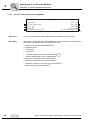
Description
The function module MC_ReadParameter_MDX/MX is used to read parameters (indices) of the drive inverter into the MOVI-PLC® control.
Input signals
The behavior of the function module MC_ReadParameter_MDX/MX is dependent on
the following input signals.
Input signal
Type
Meaning
Execute
BOOL
The input signal Execute is used to start the read process of the
parameter.
When a rising edge occurs at this input signal, the function module
starts to transfer the parameter from the drive inverter to the MOVIPLC® control.
Index
UINT
The input signal Index specifies which parameter is to be transferred
from the inverter to the MOVI-PLC® control. The index number of the
parameter can be displayed in the shell of the MOVITOOLS® MotionStudio software when you place your cursor in the relevant parameter
field and press <CTRL + F1> for MOVIDRIVE® B. The subindex number is also displayed for MOVIAXIS®.
Subindex
UINT
The input signal Subindex is only available for function module
MC_ReadParameter_MX and not for MC_ReadParameter_MDX. You
can specify which parameter is to be transferred from the MOVIAXIS®
servo inverter to the MOVI-PLC® control using the input signals Subindex and Index.
Axis
AXIS_REF
The input signal Axis specifies the motor axis on which the actions of
the function module are to be executed.
Manual – MPLCMotion_MDX and MPLCMotion_MX Libraries for MOVI-PLC®
Description of the Function Modules
MDX/MX_InverterParameters directory
Output signals
4
The function module MC_ReadParameter_MDX/MX has the following output signals:
Output signal
Type
Meaning
Done
BOOL
The output signal Done shows whether the parameter was correctly
transferred.
• TRUE: The value of the parameter at the Data output is valid.
• FALSE: The parameter has not been transferred.
Busy
BOOL
The output signal Busy shows whether the parameter is currently
being transferred.
• TRUE: The parameter is currently being transferred.
• FALSE: The parameter is currently not being transferred.
Error
BOOL
The output signal Error shows whether an error occurred in the function module.
• TRUE: An error has occurred during parameter transfer.
• FALSE: No error has occurred.
ErrorID
DWORD
This output shows the error code of the error that occurred (→ Section
"Error identifier").
Data
DINT
This output contains the transferred parameter value.
Manual – MPLCMotion_MDX and MPLCMotion_MX Libraries for MOVI-PLC®
37
Description of the Function Modules
MDX/MX_InverterParameters directory
4
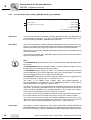
4.4.3
Function module MC_WriteParameter_MDX/MX
MC_WriteParameter_MDX
Execute : BOOL
Done : BOOL
Index : UINT
Data : DINT
NonVolatile : BOOL
Axis : AXIS_REF (VAR_IN_OUT)
Busy : BOOL
Error : BOOL
ErrorID : DWORD
Axis : AXIS_REF (VAR_IN_OUT)
58175AXX
Application
You can use the function module MC_WriteParameter_MDX/MX on all motor axes.
Important:
Changing some parameters, which require certain settings for fault-free control of the
drive inverter by the MOVI-PLC® control, can lead to unforeseeable operating states.
Therefore, the function module MC_WriteParameter_MDX/MX must only be used by
trained personnel or after testing the required functionality thoroughly, ensuring the protection of personnel and machinery.
38
Description
Function module MC_WriteParameter_MDX/MX is used to transfer parameters (indices) from the MOVI-PLC® control to the drive inverter.
Input signals
The behavior of the function module MC_WriteParameter_MDX/MX is dependent on the
following input signals:
Input signal
Type
Meaning
Execute
BOOL
The input signal Execute is used to start the parameter transfer process.
When a rising edge occurs at this input signal, the function module
starts to transfer the parameter from the MOVI-PLC® control to the
drive inverter.
Index
UINT
The input signal Index specifies which parameter is to be transferred
from the MOVI-PLC® control to the drive. The index number of the
parameter can be displayed in the shell of the MOVITOOLS® MotionStudio software when you place your cursor in the relevant parameter
field and press <CTRL + F1> for MOVIDRIVE® B. The subindex number is also displayed for MOVIAXIS®.
Subindex
UINT
The input signal Subindex is only available for function module
MC_ReadParameter_MX and not for MC_ReadParameter_MDX. You
can specify which parameter is to be transferred from the MOVI-PLC®
control to the MOVIAXIS servo inverter using the input signals Subindex and Index.
Data
DINT
The input signal Data contains the transferred parameter value.
NonVolatile
BOOL
The input signal NonVolatile specifies whether the parameter should
be copied to the non-volatile memory.
• TRUE: The parameter is transferred to the non-volatile memory
of the drive inverter. The parameter value is still stored once the
drive inverter is switched off and then on again.
• FALSE: The parameter is transferred to the volatile memory of the
drive inverter. When the drive inverter is switched off and then
back on again, the parameter is reset to its original value.
Axis
AXIS_REF
The input signal Axis specifies the motor axis on which the actions of
the function module are to be executed.
Manual – MPLCMotion_MDX and MPLCMotion_MX Libraries for MOVI-PLC®
Description of the Function Modules
MDX/MX_InverterParameters directory
Output signals
4
The function module MC_WriteParameter_MDX/MX has the following output signals:
Output signal
Type
Meaning
Done
BOOL
The output signal Done shows whether the parameter was correctly
transferred.
• TRUE: The parameter has been successfully transferred from the
MOVI-PLC® control to the drive inverter.
• FALSE: The parameter has not been transferred.
Busy
BOOL
The output signal Busy shows whether the parameter is being transferred.
• TRUE: The parameter is currently being transferred.
• FALSE: The parameter is currently not being transferred.
Error
BOOL
The output signal Error shows whether an error occurred in the function module.
• TRUE: An error has occurred during parameter transfer.
• FALSE: No error has occurred.
ErrorID
DWORD
The output signal ErrorID shows the error code of the error that
occurred (→ see Section "Error identifier").
Manual – MPLCMotion_MDX and MPLCMotion_MX Libraries for MOVI-PLC®
39
Description of the Function Modules
MDX/MX_InverterParameters directory
4
4.4.4
Function module MC_SetDynamics_MDX/MX
MC_SetDynamics_MDX
Execute : BOOL
Velocity : DINT
Acceleration : DINT
Deceleration : DINT
Done : BOOL
Axis : AXIS_REF (VAR_IN_OUT)
Busy : BOOL
Error : BOOL
ErrorID : DWORD
Axis : AXIS_REF (VAR_IN_OUT)
58176AXX
Application
You can use the function module MC_SetDynamics_MDX/MX on all motor axes.
Description
The function module MC_SetDynamics_MDX/MX is used to change the dynamic parameters while executing a task of the continuous or discrete motion function module
and function modules MC_AxisStop_MDX/MX or MC_StopSensorless_MDX. In doing
so, the input signals Velocity, Acceleration and Deceleration determine the dynamic behavior of the rotation.
If the function module MC_SetDynamics_MDX/MX is executed before a continuous or
discrete motion function module, the set dynamic parameters are overwritten with their
input signals while executing the motion function module. The behavior in conjunction
with the function module MC_QuickEnable_MDX/MX is described in the section "Function module MC_QuickEnable_MDX/MX" in the "Influence" subsection.
Input signals
40
The behavior of the function module MC_SetDynamics_MDX/MX is dependent on the
following input signals.
Input signal
Type
Meaning
Execute
BOOL
The input signal Execute starts the task of the function module.
When a rising edge occurs at this input signal, the function module
changes the dynamic parameters of the motor rotation according to
the input signals Velocity, Acceleration and Deceleration.
Velocity
DINT
The input signal Velocity specifies the motor speed during the constant speed phase.
Acceleration
DINT
The input signal Acceleration specifies the acceleration (increase of
kinetic energy in the motor).
Deceleration
DINT
The input signal Deceleration specifies the braking deceleration
(decrease of kinetic energy in the motor).
Axis
AXIS_REF
The input signal Axis specifies the motor axis on which the actions of
the function module are to be executed.
Manual – MPLCMotion_MDX and MPLCMotion_MX Libraries for MOVI-PLC®
Description of the Function Modules
MDX/MX_InverterParameters directory
Output signals
4
The function module MC_SetDynamics_MDX/MX has the following output signals:
Output signal
Type
Meaning
Done
BOOL
The output signal Done shows whether the new dynamic parameters
Velocity, Acceleration and Deceleration are successfully written.
• TRUE: Parameter has been written successfully.
• FALSE: Parameter not yet fully written.
Busy
BOOL
The output signal Busy shows whether the new dynamic parameters
are transferred to the drive inverters.
• TRUE: New dynamic parameters are transferred to the drive
inverter.
• FALSE: No new dynamic parameters are transferred to the drive
inverter.
Error
BOOL
The output signal Error shows whether an error occurred in the function module.
• TRUE: An error has occurred in the function module.
• FALSE: No error has occurred in the function module.
ErrorID
DWORD
The output signal ErrorID shows the error code of the error that
occurred (→ Section "Error identifier").
Manual – MPLCMotion_MDX and MPLCMotion_MX Libraries for MOVI-PLC®
41
Description of the Function Modules
MDX/MX_InverterParameters directory
4
4.4.5
Function module MC_SetEncoderType_MDX/MX
MC_SetEncoderType_MDX
Execute : BOOL
EncoderType : MC_ENCODER_MDX
Axis : AXIS_REF (VAR_IN_OUT)
Done : BOOL
Busy : BOOL
Error : BOOL
ErrorID : DWORD
Axis : AXIS_REF (VAR_IN_OUT)
59366AXX
Application
You can use the function module MC_SetEncoderType_MDX/MX only on motor axes
with encoders.
Description
The encoder source of the MOVIDRIVE® B / MOVIAXIS® is initially set in the control
configuration for the module parameters in MOVIDRIVE® B / MOVIAXIS®. You can use
the function module MC_SetEncoderType_MDX/MX to change the encoder source in
the program sequence.
Note:
Changing the encoder source can cause balance movements of the motor axis by shifting the machine zero.
Input signals
The behavior of the function module MC_SetEncoderType_MDX/MX is dependent on
the following input signals:
Input signal
Type
Meaning
Execute
BOOL
The input signal Execute starts the task of the function module.
When a rising edge occurs at this input signal, the encoder
changeover starts.
EncoderType
MC_ENCODER
_MDX/MX
The input signal EncoderType specifies the encoder source to be
used.
The following encoder sources can be selected for MOVIDRIVE®
B:
• MDX_ENCODER_X15 Motor encoder
• MDX_ENCODER_X14 External encoder
• MDX_ENCODER_SSI Absolute encoder
Function reserved in conjunction with MOVIAXIS® at time of
publication.
Axis
42
AXIS_REF
This input specifies the motor axis on which the actions of the function module are to be executed.
Manual – MPLCMotion_MDX and MPLCMotion_MX Libraries for MOVI-PLC®
Description of the Function Modules
MDX/MX_InverterParameters directory
Output signals
4
The function module MC_SetEncoderType_MDX/MX has the following output signals:
Output signal
Type
Meaning
Done
BOOL
The output signal Done shows whether the changeover of the encoder
source was successful.
• TRUE: The encoder source changeover was successful.
• FALSE: The encoder source changeover was not successful.
Busy
BOOL
The output signal Busy shows whether the changeover of the encoder
source is underway.
• TRUE: The encoder source changeover is underway.
• FALSE: The encoder source changeover is not underway.
Error
BOOL
The output signal Error shows whether an error occurred in the function module.
• TRUE: An error has occurred during the action.
• FALSE: No error has occurred.
ErrorID
DWORD
The output signal ErrorID shows the error code of the error that
occurred (→ Section "Error identifier").
Manual – MPLCMotion_MDX and MPLCMotion_MX Libraries for MOVI-PLC®
43
Description of the Function Modules
MDX/MX_InverterParameters directory
4
4.4.6
Function module MC_SetJerk_MDX/MX
MC_SetJerk_MDX
Execute : BOOL
JerkTime : DINT
Axis : AXIS_REF (VAR_IN_OUT)
Done : BOOL
Busy : BOOL
Error : BOOL
ErrorID : DWORD
Axis : AXIS_REF (VAR_IN_OUT)
58179AXX
Application
You can only use the function module MC_SetJerk_MDX/MX on motor axes with encoders.
Prerequisite
For the function module MC_SetJerk_MDX/MX to be executed, the motor axis must be
in PLCopenState STANDSTILL (output signal of the function module
MC_ConnectAxis_MDX).
Description
•
The function module MC_SetJerk_MDX is used to activate and deactivate the jerk
limitation of the positioning function modules. The function module
MC_SetJerk_MDX for MOVIDRIVE® B transfers the jerk time to the drive inverter.
You must not change the jerk time of the drive inverter while a travel task is being
performed.
•
The function module MC_SetJerk_MX for MOVIAXIS® is used to set the jerk limitation for all discrete and continuous motion function modules. The function module
MC_SetJerk_MX transfers the jerk in units of 1/(min×s2) to the servo inverter.
You must only change the jerk setting in the servo inverter during standstill or movement with constant speed of the connected drive.
44
•
The JerkTime input is only available for the function module MC_SetJerk_MDX for
MOVIDRIVE® B.
•
The Jerk input is only available for the function module MC_SetJerk_MX for
MOVIAXIS®.
Manual – MPLCMotion_MDX and MPLCMotion_MX Libraries for MOVI-PLC®
Description of the Function Modules
MDX/MX_InverterParameters directory
Input signals
Output signals
4
The behavior of the function module MC_SetJerk_MDX/MX is dependent on the following input signals:
Input signal
Type
Meaning
Execute
BOOL
The input signal Execute is used to start the jerk time transfer process.
When a rising edge occurs at this input signal, the function module
starts to transfer the jerk time from the MOVI-PLC® control to the drive
inverter.
JerkTime
(Only for
MOVIDRIVE® B)
DINT
The input signal JerkTime specifies the jerk time for MOVIDRIVE® B
(unit: ms, max. setting range 0.5 ... 2000).
"0": Linear ramp type
"> 5": Jerk-limited ramp type. A positioning operation is lengthened by
the jerk time compared to the corresponding positioning operation with
a linear ramp.
Jerk
(Only for
MOVIAXIS®)
DINT
The input signal Jerk specifies the jerk for MOVIAXIS® (parameter
P9582.1 Application limit maximum jerk). It is used for discrete and
continuous motion tasks (unit: 1/(min x s2), max. setting range 0 ...
(231 – 1)).
Axis
AXIS_REF
The input signal Axis specifies the motor axis on which the actions of
the function module are to be executed.
The function module MC_SetJerk_MDX/MX has the following output signals:
Output signal
Type
Meaning
Done
BOOL
The output signal Done shows whether the jerk time was correctly
transferred.
• TRUE: The jerk time has been transferred from the MOVI-PLC®
control to the inverter successfully.
• FALSE: Parameter not yet fully written.
Busy
BOOL
The output signal Busy shows whether the jerk time is being transferred.
• TRUE: The jerk time is being transferred.
• FALSE: The jerk time is not being transferred.
Error
BOOL
The output signal Error shows whether an error occurred in the function module.
• TRUE: An error has occurred during the transfer of the jerk time.
• FALSE: No error has occurred.
ErrorID
DWORD
The output signal ErrorID shows the error code of the error that
occurred (→ Section "Error identifier").
Note:
For speed-controlled travel tasks, the MOVIDRIVE® B drive inverter automatically uses
a linear ramp. When the inverter then executes a positioning task, it automatically
switches back to the set ramp or jerk time using the function module MC_SetJerk_MDX.
The set jerk time is active for each travel task for MOVIAXIS®.
Manual – MPLCMotion_MDX and MPLCMotion_MX Libraries for MOVI-PLC®
45
Description of the Function Modules
MDX/MX_InverterParameters directory
4
4.4.7
Function module MC_SetLimiter_MDX/MX
MC_SetLimiter_MDX
Execute : BOOL
Select : MC_LIMITER_MDX
MaxLimit : DINT
MinLimit : DINT
Axis : AXIS_REF (VAR_IN_OUT)
Done : BOOL
Busy : BOOL
Error : BOOL
ErrorID : DWORD
Axis : AXIS_REF (VAR_IN_OUT)
58177AXX
46
Application
You can use the function module MC_SetLimiter_MDX/MX on all motor axes.
Description
The function module MC_SetLimiter_MDX/MX is used to transfer one of the following
parameters from the MOVI-PLC® control to the inverter:
•
Minimum speed (only for MOVIDRIVE® B)
•
Maximum speed
•
Current limit
•
Torque limit
•
CCW limit switch software (only for MOVIDRIVE® B)
•
CW limit switchsoftware (only for MOVIDRIVE® B)
•
Maximum acceleration (only for MOVIAXIS®)
•
Maximum deceleration (only for MOVIAXIS®)
•
Maximum emergency stop ramp (only for MOVIAXIS®)
•
Maximum jerk (only for MOVIAXIS®)
Manual – MPLCMotion_MDX and MPLCMotion_MX Libraries for MOVI-PLC®
Description of the Function Modules
MDX/MX_InverterParameters directory
Input signals
4
The behavior of the function module MC_SetLimiter_MDX/MX is dependent on the following input signals:
Input signal
Type
Meaning
Execute
BOOL
The input signal Execute starts the task of the function module.
When a rising edge occurs at this input signal, the function module
transfers the parameter specified by the input signal Select.
Select
MC_LIMITER
_MDX/MX
The input signal Select specifies which parameter the function module
is to transfer from the MOVI-PLC® control to the inverter.
MOVIDRIVE® B:
• MDX_P301_P302_SPEED_LIMIT: The function module transfers
the parameters Minimum speed and Maximum speed.
(Unit: 1/min, maximum setting range 0... 6100)
• MDX_P303_CURRENT_LIMIT: The function module transfers the
parameter Current limit.
(Unit: % IN, maximum setting range 0... 150 % (BG0 200%))
• MDX_P304_TORQUE_LIMIT: The function module transfers the
parameter Torque limit.
(Unit: % IN, maximum setting range 0 ... 150 (BG0: 200%))
• MDX_P920_SW_LIMIT_SWITCH_CW: The function module
transfers the parameter Softwarelimit switch CW.
(Unit: increments, maximum setting range -(231-1) ... (231-1))
• MDX_P921_SW_LIMIT_SWITCH_CCW: The function module
transfers the parameter Software limit switch CCW.
(Unit: increments, maximum setting range -(231-1) ... (231-1))
MOVIAXIS®:
• MX_SPEED_LIMIT_SYSTEM: The function module transfers the
parameter System limit maximum speed.
(User-defined units, maximum setting range 0 ... 10000000)
• MX_SPEED _LIMIT_APPLICATION: The function module transfers the parameter Application limit maximum speed.
(User-defined units, maximum setting range 0 ... 10000000)
• MX_EMERGENCY_STOP_DEC_LIMIT: The function module
transfers the parameter Emergency stop deceleration.
(User-defined units, maximum setting range 0 ... 2147483647)
• MX_ACC_LIMIT_SYSTEM: The function module transfers the
parameter System limitmaximum acceleration.
(User-defined units, maximum setting range 0 ... 2147483647)
• MX_ACC_LIMIT_APPLICATION: The function module transfers
the parameter Application limitmaximum acceleration.
(User-defined units, maximum setting range 0 ... 2147483647)
• MX_DEC_LIMIT_SYSTEM: The function module transfers the
parameter System limitmaximum deceleration.
(User-defined units, maximum setting range 0 ... 2147483647)
• MX_DEC_LIMIT_APPLICATION: The function module transfers
the parameter Application limitmaximum deceleration.
(User-defined units, maximum setting range 0 ... 2147483647)
• MX_CURRENT_LIMIT: The function module transfers the parameter Current limit.
(Unit: mA, maximum setting range 0... 2000000)
• MX_TORQUE_LIMIT_SYSTEM: The function module transfers
the parameter System limitmaximum torque.
(Unit: Torque 10–3 % rated motor torque, maximum setting range
0 ...1000000)
• MX_TORQUE_LIMIT_APPLICATION: The function module transfers the parameter Application limitmaximum torque.
(Unit: Torque 10–3 % rated motor torque, maximum setting range
0 ...1000000)
• MX_JERK_LIMIT_SYSTEM: The function module transfers the
parameter System limit maximum jerk.
(Unit: 1/(min×s2), maximum setting range 0 ...2147483647)
• MX_JERK_LIMIT_APPLICATION: The function module transfers
the parameter Application limit maximum jerk.
(Unit: 1/(min×s2), maximum setting range 0 ...2147483647)
Manual – MPLCMotion_MDX and MPLCMotion_MX Libraries for MOVI-PLC®
47
Description of the Function Modules
MDX/MX_InverterParameters directory
4
Output signals
48
Input signal
Type
Meaning
MaxLimit
DINT
The input signal MaxLimit specifies the transferred parameter value.
When the input signal Select is set to
MDX_P301_302_SPEED_LIMIT, this input signal specifies the value
for the parameter P302.
(Unit and maximum setting range → Input signal Select)
MinLimit
DINT
This input is only used when the input Select is set to
MDX_P301_302_SPEED_LIMIT. In this case, it specifies the value for
parameter P301.
(Unit: 1/min, maximum setting range 0... 6100)
Axis
AXIS_REF
This input specifies the motor axis on which the actions of the function
module are to be executed.
The function module MC_SetLimiter_MDX/MX has the following output signals:
Output signal
Type
Meaning
Done
BOOL
The output signal Done shows whether the parameter was correctly
transferred.
• TRUE: The parameter has been transferred successfully from the
MOVI-PLC® control to the drive inverter.
• FALSE: Parameter not yet fully written.
Busy
BOOL
The output signal Busy shows whether the parameter is being transferred.
• TRUE: The parameter is currently being transferred.
• FALSE: The parameter is currently not being transferred.
Error
BOOL
The output signal Error shows whether an error occurred in the function module.
• TRUE: An error has occurred during parameter transfer.
• FALSE: No error has occurred.
ErrorID
DWORD
The output signal ErrorID shows the error code of the error that
occurred (→ Section "Error identifier").
Manual – MPLCMotion_MDX and MPLCMotion_MX Libraries for MOVI-PLC®
Description of the Function Modules
MDX/MX_InverterParameters directory
4.4.8
4
Function module MC_SetHomeParameters_MDX/MX
MC_SetHomeParameters_MDX
Execute : BOOL
RefSpeed1 : DINT
Done : BOOL
Busy : BOOL
Error : BOOL
ErrorID : DWORD
RefSpeed2 : DINT
RefType : DINT
ZeroPulse : BOOL
Axis : AXIS_REF (VAR_IN_OUT)
Axis : AXIS_REF (VAR_IN_OUT)
58180AXX
Application
You can use the function module MC_SetHomeParameters_MDX/MX on motor axes
with encoders.
Description
The function module MC_SetHomeParameters_MDX/MX is used to set the parameters
that are required for the motor axis to perform reference travel. The function module
MC_SetHomeParameters_MDX/MX transfers parameters required for reference travel
from the MOVI-PLC® control to the inverter.
For more information on the reference travel parameters and the reference travel types,
refer to the online help of the MOVITOOLS® MotionStudio software.
Effect
For reference travel with MOVIAXIS®, you can set additional parameters in the parameter tree (FCB12, reference travel) or by using the function module
MC_WriteParameter_MX.
Input signals
The behavior of the function module MC_SetHomeParameters_MDX/MX is dependent
on the following input signals:
Input signal
Type
Meaning
Execute
BOOL
The input signal Execute is used to start the parameter transfer process.
When a rising edge occurs at this input signal, the function module
starts to transfer the parameters from the MOVI-PLC® control to the
inverter.
RefSpeed1
DINT
The input signal RefSpeed1 specifies reference speed 1.
RefSpeed2
DINT
The input signal RefSpeed2 specifies reference speed 2.
RefType
DINT
The input signal RefType specifies the type of reference travel (0 ...8
for MOVIDRIVE® B, 0 ... 10 for MOVIAXIS®).
ZeroPulse
BOOL
The input signal ZeroPulse shows whether the motor axis is referenced to the zero pulse during reference travel.
• TRUE: The motor axis is referenced to the zero pulse during reference travel.
• FALSE: The motor axis is not referenced to the zero pulse during
reference travel.
Axis
AXIS_REF
The input signal Axis specifies the motor axis on which the actions of
the function module are to be executed.
Reference travel type 5 (= no reference travel) for MOVIDRIVE® B corresponds to the
reference travel type 6 for MOVIAXIS®.
Manual – MPLCMotion_MDX and MPLCMotion_MX Libraries for MOVI-PLC®
49
Description of the Function Modules
MDX/MX_InverterParameters directory
4
Output signals
50
The function module MC_SetHomeParameters_MDX/MX has the following output signals:
Output signal
Type
Meaning
Done
BOOL
The output signal Done shows whether all parameters were correctly
transferred.
• TRUE: All parameters have been transferred successfully from
the MOVI-PLC® control to the drive inverter.
• FALSE: Parameter not yet fully written.
Busy
BOOL
The output signal Busy shows whether the parameters are being
transferred.
• TRUE: The parameters are being transferred.
• FALSE: The parameters are not being transferred.
Error
BOOL
The output signal Error shows whether an error occurred in the function module.
• TRUE: An error has occurred during the transfer of the parameters.
• FALSE: No error has occurred.
ErrorID
DWORD
The output signal ErrorID shows the error code of the error that
occurred (→ Section "Error identifier").
Manual – MPLCMotion_MDX and MPLCMotion_MX Libraries for MOVI-PLC®
Description of the Function Modules
MDX/MX_InverterParameters directory
4.4.9
4
Function module MC_SetModuloParameters_MDX/MX
MC_SetModuloParameters_MDX
Execute : BOOL
ModuloOn : BOOL
Numerator : DINT
Denominator : DINT
EncoderResolution : UINT
Axis : AXIS_REF (VAR_IN_OUT)
Done : BOOL
Busy : BOOL
Error : BOOL
ErrorID : DWORD
Axis : AXIS_REF (VAR_IN_OUT)
58181AXX
Application
You can use the function module MC_SetModuloParameters_MDX/MX only on motor
axes with encoders.
Description
The function module MC_SetModuloParameters_MDX/MX is used to set the parameters that are required for positioning applications of the motor axis in modulo format. The
function module MC_SetModuloParameters_MDX/MX transfers the parameters required for positioning applications in modulo format from the MOVI-PLC® control to the
inverter.
For more information on the modulo parameters, refer to the online help of the
MOVITOOLS® MotionStudio software.
Notes:
•
The MPLC_CalcLCD function (Calculate Least Common Denominator) is available
in the MPLCUtilities library for calculating the least common denominator of two
natural numbers.
•
The inputs ModuloOn to EncoderResolution are only available for function module
MC_SetModuloParameters_MDX for MOVIDRIVE® B.
•
The inputs Mode to Underflow are only available for function module
MC_SetModuloParameters_MX for MOVIAXIS®.
Manual – MPLCMotion_MDX and MPLCMotion_MX Libraries for MOVI-PLC®
51
Description of the Function Modules
MDX/MX_InverterParameters directory
4
Input signals
The behavior of the function module MC_SetModuloParameters_MDX/MX is dependent on the following input signals:
Input signal
Type
Meaning
Execute
BOOL
The input signal Execute is used to start the parameter transfer
process.
When a rising edge occurs at this input signal, the function module
starts to transfer the parameters from the MOVI-PLC® control to
the drive inverter.
ModuloOn
(Only for MOVIDRIVE® B)
BOOL
Activation of the modulo function by setting the parameter P960 to
"SHORT".
Numerator
(Only for MOVIDRIVE® B)
DINT
Denominator
(Only for MOVIDRIVE® B)
DINT
EncoderResolution
(Only for MOVIDRIVE® B)
UINT
The input signal EncoderResolution specifies the resolution of the
connected encoder system.
(Unit: increments, setting range 1 ... 20000)
Mode
(Only for
MOVIAXIS®)
MC_POSMODE
_MX
•
•
•
•
•
•
•
•
Simulation of the gear unit by entering the number of teeth.
(Unit: Number of teeth, setting range 1 ... 231)
MX_ABS
MX_REL
MX_MODULO_ABS_CW
MX_MODULO_REL_CW
MX_MODULO_ABS_CCW
MX_MODULO_REL_CCW
MX_MODULO_ABS_SHORT
MX_MODULO_REL_SHORT
(See MOVIAXIS®, FCB09 operating instructions)
Output signals
52
Overflow
(Only for
MOVIAXIS®)
DINT
Parameter Modulo overflow (e.g. 359 degrees for corresponding
setting of user-defined units)
(See MOVIAXIS® operating instructions)
Underflow
(Only for
MOVIAXIS®)
DINT
Parameter Modulo underflow (e.g. "0")
(See MOVIAXIS® operating instructions)
Axis
AXIS_REF
The input signal Axis specifies the motor axis on which the actions
of the function module are to be executed.
The function module MC_SetModuloParameters_MDX/MX has the following output signals:
Output signal
Type
Meaning
Done
BOOL
The output signal Done shows whether all parameters were correctly
transferred.
• TRUE: All parameters have been transferred from the MOVIPLC® control to the inverter successfully.
• FALSE: Parameter not yet fully written.
Busy
BOOL
The output signal Busy shows whether the parameters are being
transferred.
• TRUE: The parameters are being transferred.
• FALSE: The parameters are not being transferred.
Error
BOOL
The output signal Error shows whether an error occurred in the function module.
• TRUE: An error has occurred during the transfer of the parameters.
• FALSE: No error has occurred.
ErrorID
DWORD
The output signal ErrorID shows the error code of the error that
occurred (→ Section "Error identifier").
Manual – MPLCMotion_MDX and MPLCMotion_MX Libraries for MOVI-PLC®
Description of the Function Modules
MDX/MX_Main directory
4.5
4
MDX/MX_Main directory
The MDX/MX_Main directory includes function modules for the management of:
4.5.1
•
Communication between
MDX60B/61B inverters
•
Inverters (e.g. enable, reset)
the
MOVI-PLC®
control
and
the
MOVIDRIVE®
Function module MC_ConnectAxis_MDX/MX
MC_ConnectAxis_MDX
Enable : BOOL
Node : CAN_NODE
SBUS_Address : UINT
Done : BOOL
Error : BOOL
ErrorID : DWORD
Axis : AXIS_REF
DebugInfo : MC_DEBUGINFO_MDX
PLCopenState : MC_PLCOPENSTATE
InverterData : MC_INVERTERDATA_MDX
58200AXX
Application
You can use the function module MC_ConnectAxis_MDX on all motor axes.
To ensure that communication between the MOVI-PLC® control and the
MOVIDRIVE®/MOVIAXIS® does not terminate, a different instance in each program
cycle must be called for each motor axis.
Note:
If the function module MC_ConnectAxis_MDX is not cyclically called up, the inverter issues a communication error (F46 for MOVIDRIVE® B, E67 for MOVIAXIS®) and changes to the "No enable" state.
Prerequisites
The following prerequisites must be fulfilled to establish communication between the
MOVI-PLC® control and a MOVIDRIVE® B via the function module
MC_ConnectAxis_MDX.
•
The system bus address set at the function module MC_ConnectAxis_MDX and in
the control configuration must match the address set in the inverter parameters
(P881 for SBus 1, connector X12).
•
The baud rate set in the control configuration must match the baud rate set in the inverter parameters (P884 for SBus 1, connector X12).
The startup assistant helps you to set these parameters.
Manual – MPLCMotion_MDX and MPLCMotion_MX Libraries for MOVI-PLC®
53
Description of the Function Modules
MDX/MX_Main directory
4
The following prerequisites must be fulfilled to establish communication between the
MOVI-PLC® control and a MOVIAXIS® via the function module MC_ConnectAxis_MX.
Description
•
The transmission rate set at the power supply module (switch S1 to S4) and the basic
address for the system bus (MOVIAXIS® signal bus) must correspond with the module parameters set in the control configuration. The basic address corresponds to the
SBus address of the axis module directly to the right of the power supply module. The
axis modules to the right are automatically assigned increasing addresses that must
be correspondingly set in the control configuration for the control of the motor axes.
•
The SBus address set at the function module MC_ConnectAxis_MX for each axis
must match the address set in the control configuration.
Function module MC_ConnectAxis_MDX/MX
•
Establishes the connection with the controlled motor axis
•
Is called cyclically in the program and creates a process image of the motor axes at
the place where it is called
Notes:
The process image for the inputs and outputs is created when the function module
MC_ConnectAxis_MDX/MX is called. The process image is not created at the start and
end of the control cycle.
You must use the function module MC_ConnectAxisSimulation_MDX/MX for the activated simulation of the inverter or MOVI-PLC®.
•
Activate the simulation of the MOVI-PLC® using the following menu items:
PLC editor → Menu [Online] → Menu item [Simulation]
•
Proceed as follows for the inverter simulation:
PLC editor → [Resources] tab→ Double click on [Control configuration] → Select
[MOVIDRIVE® MDX B] → Select the [Module parameter] tab in the right window →
Select entry [Simulation] in the dropdown menu of the entry [Operation mode]
Settings
54
The function module MC_ConnectAxis_MDX/MX specifies which interface the MOVIPLC® control (system bus CAN 1/2) is connected to and the system bus address that is
connected to the controlled inverter via this function module.
Manual – MPLCMotion_MDX and MPLCMotion_MX Libraries for MOVI-PLC®
Description of the Function Modules
MDX/MX_Main directory
Return values
4
The function module MC_ConnectAxis_MDX/MX provides you with various pieces of information, including:
•
Reference of the motor axis. This virtual address is used to access other function
modules on the motor axis.
•
Debugging information
– State of the system bus
– Capacity utilization of the parameter channel
– And so on
•
Current state (→ Section "State diagram")
•
Inverter data
–
–
–
–
Inverter state
Actual position of the motor axis
Actual speed of the motor axis
And so on
For more details, refer to the section "Output signals".
Effect
The following parameters of MOVIDRIVE® B are described once when the MOVI-PLC®
control is connected for the first time to MOVIDRIVE® B via the function module
MC_ConnectAxis_MDX.
Parameter
Meaning
Value entered
P885
SBus 1 synchronization ID
128
P887
Synchronization External control 1/2
On
After these parameters have been downloaded, the MOVI-PLC® control loads an
IPOSlus® program required for communication once.
The following parameters of the MOVIDRIVE® B are changed each time the power supply is switched on or when the MOVI-PLC® control is reset during the initialization of the
function module MC_ConnectAxis_MDX (first call with Enable = TRUE ):
Parameter
Meaning
P941
Source actual position
Dependent on the "Encoder type"
setting in the control configuration
for the module parameters of the
inverter.
P938 / P939
IPOS speed
Optimized for the process
Manual – MPLCMotion_MDX and MPLCMotion_MX Libraries for MOVI-PLC®
55
Description of the Function Modules
MDX/MX_Main directory
4
Input signals
The behavior of the function module MC_ConnectAxis_MDX/MX is dependent on the
following input signals:
Input signal
Type
Meaning
Enable
BOOL
The input signal Enable is used to activate the function module. The
behavior of the function module differs from the general behavior of
the input signal Enable according to section 4.1.
• TRUE: When the function module is called for the first time by setting Enable = TRUE , the function module is activated and the
applied input signals are adopted. In all the following cycles of the
MOVI-PLC® control, the function module must still be called to
prevent communication errors between the MOVI-PLC® control
and the inverter in OperationMode NORMAL (setting in the control
configuration). However, regardless of the status of the input signal Enable , changes to the input signals are no longer adopted in
the following cycles.
The function module can only be reactivated and use the modified
input signals after the MOVI-PLC® control has been reset.
• FALSE: The task of the function module will not be executed after
the MOVI-PLC® control has been switched on or reset as long as
the input signal Enable is set to FALSE. However, if the input signal Enable has been set to TRUE once, the input signal Enable no
longer has any function.
Node
CAN_NODE
The input signal Node is used to set the CAN bus node to which the
inverter is connected.
•
SBUS_NODE_1: CAN 1 (connector X33 for DHP11B; X26 for
compact control)
•
SBUS_NODE_2: CAN 2 (connector X32 for DHP11B)
SBUS_Address
UINT
The input signal SBUS_Address is used to enter the system bus
address of the connected inverter.
Note:
To transfer the input signals Node or SBUS_Address, you have to trigger a "Reset" on
the MOVI-PLC® control (in the PLC editor, menu item [Online] / [Reset]).
56
Manual – MPLCMotion_MDX and MPLCMotion_MX Libraries for MOVI-PLC®
Description of the Function Modules
MDX/MX_Main directory
Output signals
4
The function module MC_ConnectAxis_MDX/MX has the following output signals:
Output signal
Type
Meaning
Done
BOOL
The output signal Done shows whether the initialization of the function module is complete.
• TRUE: Function module MC_ConnectAxis_MDX has completed initialization and set up communication with the drive
inverter.
• FALSE: Initialization is not yet complete or there is a communication error.
Error
BOOL
The output signal Error shows whether an error occurred.
• TRUE: An error has occurred during the execution of the function module.
• FALSE: No error has occurred.
ErrorID
DWORD
The output signal ErrorID shows the error code of the error that
occurred (→ Section "Error identifier").
Axis
AXIS_REF
The output signal Axis displays the axis reference.
The output signal must be transmitted to all function modules that
refer to this physical motor axis.
DebugInfo
MC_DEBUGINF
O_MDX/MX
The output signal DebugInfo is used to locate any errors in the
Operation-Mode Debug (setting in the control configuration for the
module parameters of the drive inverter).
• ParameterChannelIdleTime: This value shows the availability
of the parameter channel in %.
0%: A parameter telegram is processed each time an
MC_ConnectAxis_MDX/MX/MC07 instance is executed.
100%: No parameter telegrams are processed.
• PDOxxTransmitCount: Number of PDOxx sent from the MOVIPLC® control to the inverter.
• PDOxxTransmitTimeStamp: Time stamp of the PDOxx sent
from the MOVI-PLC® control.
• PDOxxReceiveCount: Number of PDOxx sent from the inverter
to the MOVI-PLC® control.
• PDOxxReceiveTimeStamp: Time stamp of the PDOxx received
by the MOVI-PLC® control.
• NumberOfReceiveErrors: Number of errors that occurred when
receiving data.
• NumberOfTransmitErrors: Number of errors that occurred
when sending data.
• StateInitConnectAxis: State of function module
MC_ConnectAxis_MDX
PLCopenState
MC_
PLCOPENSTATE
The output signal PLCopenState shows information on the operating state of the motor axis (→ Section "State diagram").
• NOT_CONNECTED
• STANDSTILL
• HOMING
• DISCRETE_MOTION
• CONTINUOUS_MOTION
• STOPPING
• ERRORSTOP
Manual – MPLCMotion_MDX and MPLCMotion_MX Libraries for MOVI-PLC®
57
4
Description of the Function Modules
MDX/MX_Main directory
Output signal
Type
Meaning
InverterData
MC_INVERTER
DATA_MDX
MOVIDRIVE® B:
The output signal InverterData shows information on the operating
status of the motor axis.
• Error: An error has occurred in the inverter.
• Referenced: The inverter has been referenced.
• InverterStatus: The status of the inverter corresponds to the 7segment display on the drive inverter.
• FaultStatus: The error number of the drive inverter corresponds
to the 7-segment display when a fault occurs.
• ActualPosition: Current actual position of the motor axis in the
drive inverter. The encoder used is set in the control configuration.
• ActualModuloPosition: Current actual modulo position of the
inverter. The encoder used is set in the control configuration.
• SetpointSpeed: Setpoint speed of the motor axis in the inverter.
• ActualSpeed: Actual speed of the motor axis in the inverter
• ActualCurrent: Current active current of inverter
(Unit: 0.1% IN)
• InverterReady: The inverter is ready for operation.
MC_INVERTER
DATA_MX
MOVIAXIS® B:
The output signal InverterData shows information on the operating
status of the motor axis.
• Error: An error has occurred in the servo inverter.
• Referenced: The servo inverter is referenced.
• InverterStatus: The status of the servo inverter corresponds to
the 7-segment display on the servo inverter.
• FaultStatus: The error number of the servo inverter corresponds to the 7-segment display when a fault occurs.
• FaultSubStatus: Error number of the servo inverter when an
error occurs.
• ActualPosition: Current actual position of the motor axis in the
servo inverter.
• ActualModuloPosition: Current actual modulo position of the
servo inverter.
• ActualSpeed: Actual speed of the motor axis in the servo
inverter.
• ActualCurrent: Actual active current of the servo inverter
(Unit: mA)
• InverterReady: The servo inverter is ready for operation.
The data transfer between the drive inverter and MOVI-PLC® is described in the appendix, "Overview of the transferred MOVIDRIVE® actual values".
58
Manual – MPLCMotion_MDX and MPLCMotion_MX Libraries for MOVI-PLC®
Description of the Function Modules
MDX/MX_Main directory
4.5.2
4
Function module MC_ConnectAxisSimulation_MDX/MX
MC_ConnectAxisSimulation_MDX
Enable : BOOL
Node : CAN_NODE
SBUS_Address : UINT
Done : BOOL
Error : BOOL
ErrorID : DWORD
Axis : AXIS_REF
DebugInfo : MC_DEBUGINFO_MDX
PLCopenState : MC_PLCOPENSTATE
InverterData : MC_INVERTERDATA_MDX
59367AXX
Application
You can use the function module MC_ConnectAxisSimulation_MDX/MX on all motor
axes.
A different instance must be cyclically called for each motor axis.
Prerequisites
If the inverter / servo inverter is to be simulated, the module parameter Operation mode
of the inverter / servo inverter that is referred to by the function module must be set to
"Simulation" in the control configuration.
To simulate the MOVI-PLC® control, select the [Simulation] menu item in the [Extras]
menu in the PLC editor.
You can also activate both simulations (inverter / servo inverter and MOVI-PLC®) simultaneously. Mixed operation with simulated and real motor axes is also possible.
Description
The function module MC_ConnectAxisSimulation_MDX/MX replaces the function module MC_ConnectAxis_MDX/MX for activated simulation of inverter or MOVI-PLC®.
If the function module MC_ConnectAxisSimulation_MDX/MX is used instead of
MC_ConnextAxis_MDX/MX, the function modules MC_MoveAbsoluteModulo_MDX,
MC_MoveRelativeModulo_MDX and MC_MoveModulo_MX of the corresponding motor
axis cannot be executed.
When attempting to execute the function modules, the TRUE signal is issued at the Error
output with the ErrorID E_IEC_PARAMETER_VALUE_OUT_OF_RANGE.
Manual – MPLCMotion_MDX and MPLCMotion_MX Libraries for MOVI-PLC®
59
Description of the Function Modules
MDX/MX_Main directory
4
Input signals
The behavior of the function module MC_ConnectAxisSimulation_MDX/MX is dependent on the following input signals:
Input signal
Type
Meaning
Enable
BOOL
The input signal Enable is used to activate the function module. The
behavior of the function module differs from the general behavior of
the input signal Enable according to section 4.1.
• TRUE: When the function module is called for the first time by setting Enable = TRUE , the function module is activated and the
applied input signals are adopted. In all the following cycles, the
MOVI-PLC® control must continue to call the function module.
However, regardless of the status of the input signal Enable,
changes to the input signals are no longer adopted in the following
cycles.
The function module can only be reactivated and use the modified
input signals after the MOVI-PLC® control has been reset.
• FALSE: The task of the function module will not be executed after
the MOVI-PLC® control has been switched on or reset as long as
the input signal Enable is set to FALSE. However, if the input signal Enable has been set to TRUE once, itno longer has any function.
Node
CAN_NODE
The input signal Node is used to set the CAN bus node to which the
inverter/servo inverter is connected with the MOVI-PLC® and inverter
hardware in real-time operation.
•
SBUS_NODE_1: CAN 1 (connector X33 for DHP11B; X26 for
compact control)
•
SBUS_NODE_2: CAN 2 (connector X32 for DHP11B)
SBUS_Address
UINT
The input signal SBUS_Address is used to specify the SBus address
of the inverter / servo inverter connected with the inverter hardware in
real-time operation.
Note:
To transfer the input signals Node or SBUS_Address, you have to trigger a Reset on the
MOVI-PLC® control (in the PLC editor, menu item [Online] / [Reset]) or switch the voltage supply of the MOVI-PLC® control off and on again.
60
Manual – MPLCMotion_MDX and MPLCMotion_MX Libraries for MOVI-PLC®
Description of the Function Modules
MDX/MX_Main directory
Output signals
4
The function module MC_ConnectAxisSimulation_MDX/MX has the following output
signals:
Output signal
Type
Meaning
Done
BOOL
The output signal Done shows whether the initialization of the function module completed.
• TRUE: The function module
MC_ConnectAxisSimulation_MDX/MX has completed initialization.
• FALSE: Initialization has not yet been completed.
Error
BOOL
The output signal Error shows whether an error occurred.
• TRUE: An error has occurred during the execution of the function module.
• FALSE: No error has occurred.
ErrorID
DWORD
The output signal ErrorID shows the error code of the error that
occurred (→ Section "Error identifier").
Axis
AXIS_REF
The output signal Axis displays the axis reference.
The output signal must be transmitted to all function modules that
refer to this physical motor axis.
DebugInfo
MC_DEBUGINF
O_MDX/MX
No data is available at this output signal for function module
MC_ConnectAxisSimulation_MDX/MX.
PLCopenState
MC_
PLCOPENSTATE
The output signal PLCopenState shows information on the operating state of the simulated motor axis (→ Section "State diagram"):
• NOT_CONNECTED
• STANDSTILL
• HOMING
• DISCRETE_MOTION
• CONTINUOUS_MOTION
• STOPPING
• ERRORSTOP
InverterData
MC_INVERTER
DATA_MDX
MOVIDRIVE® B:
The output signal InverterData shows information on the operating
status of the motor axis.
• Error: Always FALSE.
• Referenced: Always TRUE.
• InverterStatus:
– "1": Controller inhibit
– "2": No enable
– "5": Speed control
– "A": Positioning
•
•
•
•
•
•
•
MC_INVERTER
DATA_MX
FaultStatus: Always "0".
ActualPosition: Value of the profile generator.
ActualModuloPosition: Always "0".
SetpointSpeed: Value of the profile generator.
ActualSpeed: Value of the profile generator.
ActualCurrent: Always "0".
InverterReady: Always TRUE.
MOVIAXIS®:
The output signal InverterData shows information on the operating
status of the motor axis.
• Error: Always FALSE.
• Referenced: Always TRUE.
• InverterStatus:
– "1": Controller inhibit
– "5": Speed control
– "9": Positioning
– "12": Homing
– "13": No enable
•
•
•
•
•
•
•
FaultStatus: Always "0".
FaultSubStatus: Always "0".
ActualPosition: Value of the profile generator.
ActualModuloPosition: Always "0".
ActualSpeed: Value of the profile generator.
ActualCurrent: Always "0".
InverterReady: Always TRUE.
Manual – MPLCMotion_MDX and MPLCMotion_MX Libraries for MOVI-PLC®
61
Description of the Function Modules
MDX/MX_Main directory
4
4.5.3
Function module MC_Power_MDX/MX
MC_Power_MDX
Enable : BOOL
PowerOffMode: MC_POWEROFFMODE_MDX
Axis : AXIS_REF (VAR_IN_OUT)
Status : BOOL
Error : BOOL
ErrorID : DWORD
Axis : AXIS_REF (VAR_IN_OUT)
58159AXX
Application
You can use the function module MC_Power_MDX/MX on all motor axes with encoders.
Note:
You must not call the function module MC_Power_MDX/MX on drives without encoders.
Description
The function module MC_Power_MDX switches a MOVIDRIVE® B unit
•
On (inverter status A or 5, depending on the selected operating mode)
•
Off (inverter status 1 or 2, depending on the PowerOffMode set)
The function module MC_Power_MX switches a MOVIAXIS® unit
Interruption
•
On (status 9 or 5, depending on the selected operating mode)
•
Off (status 1 or 13, depending on the PowerOffMode set)
If the input signal Enable is reset to FALSE, the function module MC_Power_MDX/MX
interrupts the motion function module that is currently controlling the motor axis. The output signal Active of the motion function module is reset to FALSE.
When the input signal Enable of the function module MC_Power_MDX/MX is set to
TRUE again, the motion function module continues its previous motion task.
Exception: When the axis is located in position control after positioning has been
completed and the input signal Enable is set to FALSE, the axis can be moved out of its
position due to mechanical forces. The axis returns to the last controlled target position
after it has been enabled again.
62
Manual – MPLCMotion_MDX and MPLCMotion_MX Libraries for MOVI-PLC®
Description of the Function Modules
MDX/MX_Main directory
Input signals
4
The behavior of the function module MC_Power_MDX/MX is dependent on the following
input signals:
Input signal
Type
Meaning
Enable
BOOL
The input signal Enable is used to switch the inverter on and off. The
function module is executed with the current input values, even if the
input signal Enable is set to FALSE.
• TRUE: The inverter is switched on when the input signal Enable is
set to TRUE (inverter status for MOVIDRIVE® B: A or 5 for
MOVIAXIS®: 9 or 5. Depending on the operating mode that was
set for the motor startup when switched on for the first time. In the
operating mode of the last motion function module executed for
further switching on processes.)
• FALSE: The inverter is switched off when the input signal Enable
is set to FALSE (inverter status for MOVIDRIVE® B: 1 or 2 for
MOVIAXIS® 1 or 13 depending on PowerOffMode input).
PowerOffMode
MC_POWER
OFFMODE_
MDX
/MX
The input signal PowerOffMode is used to set the status of the inverter
when it is switched off using the function module MC_Power_MDX.
• MDX/MX_CTRL_INHIBIT: The inverter status is now Controller
inhibit (-> MDX: InverterStatus 1; MX: Status 1). The motor brake
is applied. If no brake is installed, the motor will coast to a halt.
• MDX/MX_NO_ENABLE: The inverter changes to the No enable
status (-> MDX: InverterStatus 2; MX: Status 13). The motor is
controlled and slowed down. Whether the motor brake is activated
in the No enable status depends on the parameter P730 for
MOVIDRIVE® B and the indices 8584.0 and 9833.1 for
MOVIAXIS®. The brake function is switched on as the default setting. This means the brake is activated shortly before reaching
standstill for MOVIDRIVE® B and after reaching standstill for
MOVIAXIS® (the brake is always activated in the Controller inhibit
status).
This input signal is also used to switch between Controller inhibit and
No enable when the inverter is switched off (Enable = FALSE)
Axis
Output signals
AXIS_REF
The input signal Axis specifies the motor axis on which the actions of
the function module are to be executed.
The function module MC_Power_MDX/MX has the following output signals:
Output signal
Type
Meaning
Status
BOOL
The output signal Status shows whether the inverter is switched on or
off.
• TRUE: The inverter is switched on (inverter status for
MOVIDRIVE® B: A or 5 for MOVIAXIS®: 9 or 5, depending on the
set operating mode).
• FALSE: The inverter is switched off (inverter status for
MOVIDRIVE® B: 1 or 2 for MOVIAXIS® 1 or 13, depending on the
PowerOffMode input signal)
Error
BOOL
The output signal Error shows whether an error occurred in the function module.
• TRUE: An error has occurred during the execution of the function
module.
• FALSE: No errors have occurred in the function module.
ErrorID
DWORD
The output signal ErrorID shows the error code of the error that
occurred (→ Section "Error identifier").
To be able to switch on the inverter using the function module MC_Power_MDX/MX, you
must set the binary input DI00 (MOVIDRIVE® B: "/CONTROLLER INHIBIT", MOVIAXIS®: "OUTPUT STAGE ENABLE"). Additional binary input parameters set to
"Enable", "Stop" or "Hold control" must be switched accordingly.
Manual – MPLCMotion_MDX and MPLCMotion_MX Libraries for MOVI-PLC®
63
Description of the Function Modules
MDX/MX_Main directory
4
4.5.4
Function module MC_QuickEnable_MDX/MX
MC_QuickEnable_MDX
Enable : BOOL
QuickEnable : BOOL
Axis : AXIS_REF (VAR_IN_OUT)
Done : BOOL
Busy : BOOL
Error : BOOL
ErrorID : DWORD
59368AXX
Application
You can only use the function module MC_QuickEnable_MDX/MX on motor axes with
encoders.
Prerequisites
The motor axis must be enabled using the function module MC_Power_MDX/MX (input
signal Enable = TRUE) before using the function module MC_QuickEnable_MDX/MX.
Description
When executing this function module, an enable request or enable revoke is immediately sent to the inverter / servo inverter depending on the assignment of the input signals.
In contrast, the enable request or enable revoke is executed after the next execution of
the function module MC_ConnectAxis_MDX/MX in the inverter when using the function
module MC_Power_MDX/MX.
If the function module MC_QuickEnable_MDX/MX is first called with the input signals
Enable = TRUE and QuickEnable = FALSE and a travel task is then started, the inverter
starts the travel task directly after the following call up of the function module
MC_QuickEnable_MDX/MX with both input signals = TRUE. The immediate cancellation of a travel task and its subsequent continuation is also possible using
MC_QuickEnable_MDX/MX. To do this, you must assign the input signal QuickEnable
to FALSE or TRUE for the corresponding call up procedures.
Notes:
64
•
The function module MC_QuickEnable_MDX/MX has been optimized for short response times. As a single function module of the MPLCMotion_MDX/MX library, it
can also be executed in another task, for example one that is faster than the other
function modules.
•
The function module MC_QuickEnable_MDX/MX blocks the task in which it was executed as well as all tasks with lower priority during its execution (until the send buffer
of the system bus is free). For this reason, the function module
MC_QuickEnable_MDX/MX can only be used specifically and sparingly.
•
Use the function module MC_Stop_MDX/MX or MC_AxisStop_MDX/MX to stop a
motor axis and cancel an active travel task.
•
You must not use the function module MC_QuickEnable_MDX/MX in conjunction
with modulo positioning.
Manual – MPLCMotion_MDX and MPLCMotion_MX Libraries for MOVI-PLC®
Description of the Function Modules
MDX/MX_Main directory
Effect
Input signals
Output signals
•
The start / stop ramps for activating or deactivating enable using
MC_QuickEnable_MDX/MX
can
be
set
with
the
function
module
MC_SetDynamics_MDX/MX. If a continuous motion travel task is executed between
the execution of MC_SetDynamics_MDX/MX and MC_QuickEnable_MDX/MX, the
dynamic parameters set at the associated function module are also used for the execution of MC_QuickEnable_MDX/MX. The execution of a discrete motion travel
task does not influence dynamic parameters used by MC_QuickEnable_MDX/MX.
•
The acceleration / braking movement triggered by the function module
MC_QuickEnable_MDX for MOVIDRIVE® B is executed using the ramps "t11
up/down CW/CCW" in the parameters P130 to P133. The startup assistant helps you
to set these parameters.
•
The brake function should be switched off so that the inverter can start as soon as
possible when enabled with MC_QuickEnable_MDX/MX (for MOVIDRIVE® B P730;
indices 8584.0 and 9833.1 for MOVIAXIS®).
4
The behavior of the function module MC_QuickEnable_MDX/MX is dependent on the
following input signals:
Input signal
Type
Meaning
Enable
BOOL
The input signal Enable is used to activate the function module.
The task of the function module is only executed when the input signal
Enable is set to TRUE.
QuickEnable
BOOL
The input signal QuickEnable is used to switch the inverter / servo
inverter on and off.
• TRUE: The inverter / servo inverter is switched on when the input
signal QuickEnable is set to TRUE (in the operating mode that
was active before deactivating enable).
• FALSE: The inverter / servo inverter is switched off when the input
signal Enable is set to FALSE (MOVIDRIVE® B: Status 2;
MOVIAXIS®: Status 13, depending on the PowerOffMode input of
the function module MC_Power_MDX/MX).
Axis
AXIS_REF
The input signal Axis specifies the motor axis on which the actions of
the function module are to be executed.
The function module MC_QuickEnable_MDX/MX has the following output signals:
Output
Type
Meaning
Done
BOOL
The output signal Done shows whether the enable command was
issued or revoked.
• TRUE: Enable command was successfully issued.
• FALSE: Enable command was not successfully issued.
Busy
BOOL
The output signal Busy shows whether the enable command is being
issued or revoked.
• TRUE: Enable command is being issued or revoked.
• FALSE: Enable command is not being issued or revoked.
Error
BOOL
The output signal Error shows whether an error occurred in the function module.
• TRUE: An error has occurred during the execution of the function
module.
• FALSE: No errors have occurred in the function module.
ErrorID
DWORD
The output signal ErrorID shows the error code of the error that
occurred (→ Section "Error identifier").
Manual – MPLCMotion_MDX and MPLCMotion_MX Libraries for MOVI-PLC®
65
Description of the Function Modules
MDX/MX_Main directory
4
4.5.5
Function module MC_Reset_MDX/MX
MC_Reset_MDX
Execute : BOOL
Axis : AXIS_REF (VAR_IN_OUT)
Done : BOOL
Busy : BOOL
Error : BOOL
ErrorID : DWORD
Axis : AXIS_REF (VAR_IN_OUT)
58160AXX
Application
You can use the function module MC_Reset_MDX/MX on all motor axes.
Description
The function module MC_Reset_MDX/MX is used to acknowledge inverter errors.
Errors that occur in a function module of the MPLCMotion_MDX/MX library are not acknowledged by this function module. These errors reset themselves automatically once
the cause of the error has been removed.
Input signals
Output signals
66
The behavior of the function module MC_Reset_MDX/MX is dependent on the following
input signals:
Input signal
Type
Meaning
Execute
BOOL
The input signal Execute is used to acknowledge inverter errors.
When a rising edge occurs at this input signal, the function module
resets the inverter error.
Axis
AXIS_REF
The input signal Axis specifies the motor axis on which the actions of
the function module are to be executed.
The function module MC_Reset_MDX/MX has the following output signals:
Output
Type
Meaning
Done
BOOL
The output signal Done shows whether a reset was executed.
• TRUE: Reset successful.
• FALSE: Reset unsuccessful.
Busy
BOOL
The output signal Busy shows whether the inverter error has been
reset.
• TRUE: The function module is currently resetting the inverter
error.
• FALSE: The function module is not currently resetting the inverter
error.
Error
BOOL
The output signal Error shows whether an error occurred in the function module.
• TRUE: An error has occurred during the execution of the function
module.
• FALSE: No errors have occurred in the function module.
ErrorID
DWORD
The output signal ErrorID shows the error code of the error that
occurred (→ Section "Error identifier").
Manual – MPLCMotion_MDX and MPLCMotion_MX Libraries for MOVI-PLC®
Description of the Function Modules
MDX/MX_SingleAxis directory
4.6
4
MDX/MX_SingleAxis directory
The MDX/MX_SingleAxis directory contains function modules that enable motion
tasks for a motor axis with encoder.
4.6.1
Function module MC_MoveVelocity_MDX/MX
MC_MoveVelocity_MDX
Execute : BOOL
Velocity : DINT
Acceleration : DINT
Deceleration : DINT
Axis : AXIS_REF (VAR_IN_OUT)
InVelocity : BOOL
Active : BOOL
CommandAborted : BOOL
Error : BOOL
ErrorID : DWORD
Axis : AXIS_REF (VAR_IN_OUT)
58162AXX
Application
You can only use the function module MC_MoveVelocity_MDX/MX on motor axes with
encoders.
Prerequisite
For the function module MC_MoveVelocity_MDX to be executed for MOVIDRIVE® B,
the motor axis must be assigned the status STANDSTILL or CONTINUOUS_MOTION
in PLCopenState (output signal of the function module MC_ConnectAxis_MDX).
For the function module MC_MoveVelocity_MX to be executed for MOVIAXIS®, the
motor axis must be assigned the status STANDSTILL,CONTINUOUS_MOTION or
DISCRETE_MOTION in PLCopenState (output signal of the function module
MC_ConnectAxis_MX).
Description
The function module MC_MoveVelocity_MDX/MX starts continuous rotation of a motor
axis.
The input signals Velocity, Acceleration and Deceleration determine the dynamic behavior of the rotation.
Cancellation
The speed control triggered by the function module MC_MoveVelocity_MDX/MX is cancelled by the function modules MC_Stop_MDX/MX and MC_AxisStop_MDX/MX (→
Section 4.1).
Effect
Set the speed window to the target setpoint speed for the output of the signal TRUE at
the output InVelocity using the following parameters:
•
MOVIDRIVE® B: in the startup assistant, P411 Range width (→ Section "Startup")
•
MOVIAXIS®: Parameter "PLC library speed window P1" index 10407.1
Manual – MPLCMotion_MDX and MPLCMotion_MX Libraries for MOVI-PLC®
67
Description of the Function Modules
MDX/MX_SingleAxis directory
4
Input signals
Output signals
68
The behavior of the function module MC_MoveVelocity_MDX/MX is dependent on the
following input signals:
Input signal
Type
Meaning
Execute
BOOL
The input signal Execute starts the task of the function module.
When a rising edge occurs at this input signal, the function module
starts the speed control.
Velocity
DINT
The input signal Velocity specifies the motor speed during the constant speed phase.
Acceleration
DINT
The input signal Acceleration specifies the acceleration (increase of
kinetic energy in the motor).
Deceleration
DINT
The input signal Deceleration specifies the braking deceleration
(decrease of kinetic energy in the motor).
Axis
AXIS_REF
The input signal Axis specifies the motor axis on which the actions of
the function module are to be executed.
The function module MC_MoveVelocity_MDX/MX has the following output signals:
Output signal
Type
Meaning
InVelocity
BOOL
The output signal InVelocity shows whether the motor axis turns at the
target setpoint speed.
• TRUE: The motor axis turns at the speed specified by the input
signal Velocity.
• FALSE: The motor axis is accelerated or decelerated to reach the
target setpoint speed.
Active
BOOL
The output signal Active shows whether the motor axis is accelerated
to reach the setpoint speed.
• TRUE: The motor axis is accelerated or decelerated.
• FALSE: The motor axis is not accelerated or decelerated.
CommandAborted
BOOL
The output signal CommandAborted shows whether the task of the
function module has been cancelled.
• TRUE: The task of the function module has been cancelled.
• FALSE: The task of the function module has not been cancelled.
Error
BOOL
The output signal Error shows whether an error occurred in the function module.
• TRUE: An error has occurred in the function module.
• FALSE: No errors have occurred in the function module.
ErrorID
DWORD
The output signal ErrorID shows the error code of the error that
occurred (→ Section "Error identifier").
Manual – MPLCMotion_MDX and MPLCMotion_MX Libraries for MOVI-PLC®
Description of the Function Modules
MDX/MX_SingleAxis directory
4.6.2
4
Function module MC_MoveAbsolute_MDX/MX
MC_MoveAbsolute_MDX
Execute : BOOL
Position : DINT
Velocity : DINT
Acceleration : DINT
Deceleration : DINT
Axis : AXIS_REF (VAR_IN_OUT)
Done : BOOL
Active : BOOL
CommandAborted : BOOL
Error : BOOL
ErrorID : DWORD
Axis : AXIS_REF (VAR_IN_OUT)
58163AXX
Application
You can only use the function module MC_MoveAbsolute_MDX/MX on motor axes with
encoders.
Prerequisite
•
For the function module MC_MoveAbsolute_MDX to be executed for MOVIDRIVE®
B, the motor axis must be assigned the status STANDSTILL or
DISCRETE_MOTION in PLCopenState (output signal of the function module
MC_ConnectAxis_MDX).
•
For the function module MC_MoveAbsolute_MX to be executed for MOVIAXIS®, the
motor axis must be assigned the status STANDSTILL, DISCRETE_MOTION or
CONTINUOUS_MOTION in PLCopenState (output signal of the function module
MC_ConnectAxis_MX).
•
The axis must also be referenced. Exception for MOVIDRIVE® B: The function module MC_InitialConfig_MDX was first executed with the input signal UseMoveAbsoluteWithoutReference = TRUE.
Description
Effect
The function module MC_MoveAbsolute_MDX/MX starts the movement of a motor axis
to an absolute axis position.
•
The input signals Velocity, Acceleration and Deceleration determine the dynamic
behavior of the rotation.
•
The motor axis remains at the target position subject to position control.
The following parameters of the MOVIDRIVE® B drive inverter have a direct effect on
the execution of the function module MC_MoveAbsolute_MDX.
•
You can use parameters P916 Ramp type and P933 Jerk time to define positioning
ramps with jerk limitation. Use function module MC_SetJerk_MDX to set these parameters.
•
Use parameter P922 Positioning window to set the positioning window to the target
position, within which the function module sets the output signal Done to TRUE "Target position reached".
The startup assistant helps you to set these parameters.
The following parameters of the MOVIAXIS® servo inverter have a direct effect on the
execution of the function module MC_MoveAbsolute_MX.
•
Define the jerk for positioning ramps using index 9582.1. Use function module
MC_SetJerk_MX to set these parameters.
•
Use index 9885.3 to set the positioning window to the target position, within which
the function module sets the output signal Done to TRUE "Target position reached".
Manual – MPLCMotion_MDX and MPLCMotion_MX Libraries for MOVI-PLC®
69
Description of the Function Modules
MDX/MX_SingleAxis directory
4
Input signals
Output signals
70
The behavior of the function module MC_MoveAbsolute_MDX/MX is dependent on the
following input signals:
Input signal
Type
Meaning
Execute
BOOL
The input signal Execute is used to start the motor axis rotation.
When a rising edge occurs at this input signal, the function module
starts motor axis rotation.
Position
DINT
The input signal Position specifies the target position of the motor axis
rotation.
Velocity
DINT
The input signal Velocity specifies the motor speed during the constant speed phase.
Acceleration
DINT
The input signal Acceleration specifies the acceleration (increase of
kinetic energy in the motor).
Deceleration
DINT
The input signal Deceleration specifies the braking deceleration
(decrease of kinetic energy in the motor).
Axis
AXIS_REF
The input signal Axis specifies the motor axis on which the actions of
the function module are to be executed.
The function module MC_MoveAbsolute_MDX/MX has the following output signals:
Output signal
Type
Meaning
Done
BOOL
The output signal Done shows whether the motor axis has been positioned.
• TRUE: The motor axis has performed the rotation. The motor axis
has reached the target position window.
• FALSE: The motor axis has not completed the rotation. The motor
axis has not yet reached the target position window.
Active
BOOL
The output signal Active shows whether the motor axis is turning to
reach the target position window.
• TRUE: The motor axis is rotating.
• FALSE: The motor axis is not rotating.
CommandAborted
BOOL
The output signal CommandAborted shows whether another function
module has cancelled the task of the function module.
• TRUE: Another function module has cancelled the task of the
function module.
• FALSE: The task of the function module has not been cancelled.
Error
BOOL
The output signal Error shows whether an error occurred in the function module.
• TRUE: An error has occurred in the function module.
• FALSE: No errors have occurred in the function module.
ErrorID
DWORD
The output signal ErrorID shows the error code of the error that
occurred (→ Section "Error identifier").
Manual – MPLCMotion_MDX and MPLCMotion_MX Libraries for MOVI-PLC®
Description of the Function Modules
MDX/MX_SingleAxis directory
4.6.3
4
Function module MC_MoveAbsoluteModulo_MDX
MC_MoveAbsoluteModulo_MDX
Execute : BOOL
ModuloPosition : DINT
Velocity : DINT
Acceleration : DINT
Deceleration : DINT
Mode : MC_MODULO_MODE_MDX
Done : BOOL
Active : BOOL
CommandAborted : BOOL
Error : BOOL
ErrorID : DWORD
Axis : AXIS_REF (VAR_IN_OUT)
Axis : AXIS_REF (VAR_IN_OUT)
58164AXX
Application
You can use the function module MC_MoveAbsoluteModulo_MDX only on motor axes
with encoders.
Prerequisites
•
For the function module MC_MoveAbsoluteModulo_MDX to be executed for
MOVIDRIVE® B, the motor axis must be assigned the status STANDSTILL or
DISCRETE_MOTION in PLCopenState (output signal of the function module
MC_ConnectAxis_MDX).
•
The function module MC_SetModuloParameters_MDX must first have been executed for this motor axis.
•
The axis must also be referenced. Exception: The function module
MC_InitialConfig_MDX was first executed with the input signal UseMoveAbsoluteWithoutReference = TRUE.
Description
The function module MC_MoveAbsoluteModulo_MDX starts the movement of a motor
axis to an absolute axis position in modulo format. A motor axis rotation of 360° corresponds to 216 increments.
•
The input signals Velocity, Acceleration and Deceleration determine the dynamic behavior of the rotation.
•
The input signal Mode specifies the strategy of the task (short distance, clockwise,
counterclockwise).
•
The motor axis remains at the target position subject to position control.
For more information on position specification and position management, refer to the
"Positioning and sequence control IPOSplus®" system manual.
Note:
Set the required gear unit and encoder data using the function module
MC_SetModuloParameters_MDX.
Manual – MPLCMotion_MDX and MPLCMotion_MX Libraries for MOVI-PLC®
71
Description of the Function Modules
MDX/MX_SingleAxis directory
4
Effect
The following parameters of the MOVIDRIVE® MDX60B/61B have a direct effect on the
execution of the function module MC_MoveAbsoluteModulo_MDX.
•
You can use parameters P916 Ramp type and P933 Jerk time to define positioning
ramps with jerk limitation. Use function module MC_SetJerk_MDX to set these parameters.
•
Use parameter P922 Positioning window to set the positioning window to the target
position, within which the function module sets the output signal Done to TRUE "Target position reached".
The startup assistant helps you to set these parameters.
Input signals
72
The behavior of the function module MC_MoveAbsoluteModulo_MDX is dependent on
the following input signals:
Input signal
Type
Meaning
Execute
BOOL
The input signal Execute is used to start the motor axis rotation.
When a rising edge occurs at this input signal, the function module
starts the motor axis rotation.
ModuloPosition
DINT
The input signal Position specifies the target position of the motor axis
rotation.
216 increments correspond to a motor axis rotation of 360° for
MOVIDRIVE® B (unit: modulo increments). The number of complete
rotations is specified in the high word and the target angle between 0°
and 360° in the low word. The maximum setting range is dependent
on the modulo numerator, denominator and encoder resolution.
Velocity
DINT
The input signal Velocity specifies the motor speed during the constant speed phase.
Acceleration
DINT
The input signal Acceleration specifies the acceleration (increase of
kinetic energy in the motor).
Deceleration
DINT
The input signal Deceleration specifies the braking deceleration
(decrease of kinetic energy in the motor).
Mode
MC_
MODULO_
MODE_MDX
The input signal Mode specifies the travel strategy.
• MDX_OFF: Modulo functionality deactivated
• MDX_SHORT: Short distance
• MDX_CW: Clockwise rotation
• MDX_CCW: Counterclockwise rotation
Axis
AXIS_REF
The input signal Axis specifies the motor axis on which the actions of
the function module are to be executed.
Manual – MPLCMotion_MDX and MPLCMotion_MX Libraries for MOVI-PLC®
Description of the Function Modules
MDX/MX_SingleAxis directory
Output signals
4
The function module MC_MoveAbsoluteModulo_MDX/MX has the following output signals:
Output signal
Type
Meaning
Done
BOOL
The output signal Done shows whether the motor axis has been positioned.
• TRUE: The motor axis has performed the rotation. The motor axis
has reached the target position window.
• FALSE: The motor axis has not completed the rotation. The motor
axis has not yet reached the target position window.
Active
BOOL
The output signal Active shows whether the motor axis is turning to
reach the target position window.
• TRUE: The motor axis is rotating.
• FALSE: The motor axis is not rotating.
CommandAborted
BOOL
The output signal CommandAborted shows whether another function
module has cancelled the task of the function module.
• TRUE: Another function module has cancelled the task of the
function module.
• FALSE: The task of the function module has not been cancelled.
Error
BOOL
The output signal Error shows whether an error occurred in the function module.
• TRUE: An error has occurred in the function module.
• FALSE: No errors have occurred in the function module.
ErrorID
DWORD
The output signal ErrorID shows the error code of the error that
occurred (→ Section "Error identifier").
Manual – MPLCMotion_MDX and MPLCMotion_MX Libraries for MOVI-PLC®
73
Description of the Function Modules
MDX/MX_SingleAxis directory
4
4.6.4
Function module MC_MoveRelative_MDX/MX
MC_MoveRelative_MDX
Execute : BOOL
Distance : DINT
Velocity : DINT
Acceleration : DINT
Deceleration : DINT
Axis : AXIS_REF (VAR_IN_OUT)
Done : BOOL
Active : BOOL
CommandAborted : BOOL
Error : BOOL
ErrorID : DWORD
Axis : AXIS_REF (VAR_IN_OUT)
58165AXX
Application
You can use the function module MC_MoveRelative_MDX/MX on all motor axes with
encoders.
Prerequisites
•
For the function module MC_MoveRelative_MDX to be executed for
MOVIDRIVE® B, the motor axis must be assigned the status STANDSTILL or
DISCRETE_MOTION in PLCopenState (output signal of the function module
MC_ConnectAxis_MDX).
•
For the function module MC_MoveRelative_MX to be executed for MOVIAXIS®, the
motor axis must be assigned the status STANDSTILL, DISCRETE_MOTION or
CONTINUOUS_MOTION in PLCopenState (output signal of the function module
MC_ConnectAxis_MX).
Description
Effect
The function module MC_MoveRelative_MDX/MX is used to move the motor axis by a
specified distance.
•
The input signals Velocity, Acceleration and Deceleration determine the dynamic behavior of the rotation.
•
The motor axis remains at the target position subject to position control.
The following parameters of the MOVIDRIVE® B have a direct effect on the execution
of the function module MC_MoveRelative_MDX/MX.
•
You can use parameters P916 Ramp type and P933 Jerk time to define positioning
ramps with jerk limitation. Use function module MC_SetJerk_MDX/MX to set these
parameters.
•
Use parameter P922 Positioning window to set the positioning window to the target
position, within which the function module sets the output signal Done to TRUE "Target position reached".
The startup assistant helps you to set these parameters.
The following parameters of the MOVIAXIS® servo inverter have a direct effect on the
execution of the function module MC_MoveAbsolute_MX.
74
•
Define the jerk for positioning ramps using index 9582.1. Use function module
MC_SetJerk_MX to set these parameters.
•
Use index 9885.3 to set the positioning window to the target position, within which
the function module sets the output signal Done to TRUE "Target position reached".
Manual – MPLCMotion_MDX and MPLCMotion_MX Libraries for MOVI-PLC®
Description of the Function Modules
MDX/MX_SingleAxis directory
Input signals
Output signals
4
The behavior of the function module MC_MoveRelative_MDX/MX is dependent on the
following input signals:
Input signal
Type
Meaning
Execute
BOOL
The input signal Execute is used to start the motor axis rotation.
When a rising edge occurs at this input signal, the function module
starts motor axis rotation.
Distance
DINT
The input signal Distance specifies the target position of the motor
axis rotation as a position relative to the current motor axis position
when the function module starts.
Velocity
DINT
The input signal Velocity specifies the motor speed during the constant speed phase.
Acceleration
DINT
The input signal Acceleration specifies the acceleration (increase of
kinetic energy in the motor).
Deceleration
DINT
The input signal Deceleration specifies the braking deceleration
(decrease of kinetic energy in the motor).
Axis
AXIS_REF
The input signal Axis specifies the motor axis on which the actions of
the function module are to be executed.
The function module MC_MoveRelative_MDX/MX has the following output signals:
Output signal
Type
Meaning
Done
BOOL
The output signal Done shows whether the motor axis has been positioned.
• TRUE: The motor axis has performed the rotation. The motor axis
has reached the target position window.
• FALSE: The motor axis has not completed the rotation. The motor
axis has not yet reached the target position window.
Active
BOOL
The output signal Active shows whether the motor axis is turning to
reach the target position window.
• TRUE: The motor axis is rotating.
• FALSE: The motor axis is not rotating.
CommandAborted
BOOL
The output signal CommandAborted shows whether another function
module has cancelled the task of the function module.
• TRUE: Another function module has interrupted the task of the
function module.
• FALSE: The task of the function module has not been cancelled.
Error
BOOL
The output signal Error shows whether an error occurred in the function module.
• TRUE: An error has occurred in the function module.
• FALSE: No errors have occurred in the function module.
ErrorID
DWORD
The output signal ErrorID shows the error code of the error that
occurred (→ Section "Error identifier").
Manual – MPLCMotion_MDX and MPLCMotion_MX Libraries for MOVI-PLC®
75
Description of the Function Modules
MDX/MX_SingleAxis directory
4
4.6.5
Function module MC_MoveRelativeModulo_MDX
MC_MoveRelativeModulo_MDX
Execute : BOOL
Distance : DINT
Velocity : DINT
Acceleration : DINT
Deceleration : DINT
Axis : AXIS_REF (VAR_IN_OUT)
Done : BOOL
Active : BOOL
CommandAborted : BOOL
Error : BOOL
ErrorID : DWORD
Axis : AXIS_REF (VAR_IN_OUT)
58166AXX
Application
Function module MC_MoveRelativeModulo_MDX
can only be used on motor axes with encoders.
Prerequisites
Description
•
For the function module MC_MoveRelativeModulo_MDX to be executed for
MOVIDRIVE® B, the motor axis must be assigned the status STANDSTILL or
DISCRETE_MOTION in PLCopenState (output signal of the function module
MC_ConnectAxis_MDX).
•
The function module MC_SetModuloParameters_MDX must first be executed for
this motor axis.
The function module MC_MoveRelativeModulo_MDX starts the movement of a motor
axis at a specified distance in modulo format.
•
The input signals Velocity, Acceleration and Deceleration determine the dynamic behavior of the rotation.
•
The motor axis remains at the target position subject to position control.
Note:
Set the required gear unit and encoder data using the function module
MC_SetModuloParameters_MDX.
Effect
The following parameters of the MOVIDRIVE® MDX60B/61Bhave a direct effect on the
execution of the function module MC_MoveRelative_MDX.
•
You can use parameters P916 Ramp type and P933 Jerk time to define positioning
ramps with jerk limitation. Use function module MC_SetJerk_MDX to set these parameters.
•
Use parameter P922 Positioning window to set the positioning window to the target
position, within which the function module sets the output signal Done to TRUE "Target position reached".
The startup assistant helps you to set these parameters.
76
Manual – MPLCMotion_MDX and MPLCMotion_MX Libraries for MOVI-PLC®
Description of the Function Modules
MDX/MX_SingleAxis directory
Input signals
Output signals
4
The behavior of the function module MC_MoveRelativeModulo_MDX is dependent on
the following input signals:
Input signal
Type
Meaning
Execute
BOOL
The input signal Execute is used to start the motor axis rotation.
When a rising edge occurs at this input signal, the function module
starts motor axis rotation.
Distance
DINT
The input signal Distance specifies the target position of the motor
axis rotation as a position relative to the current motor axis position
when the function module starts.
216 increments correspond to a motor axis rotation of 360° for
MOVIDRIVE® B (unit: modulo increments). The number of complete
rotations is specified in the high word and the target angle between 0°
and 360° in the low word. The maximum setting range is dependent
on the modulo numerator, denominator and encoder resolution.
Velocity
DINT
The input signal Velocity specifies the motor speed during the constant speed phase.
Acceleration
DINT
The input signal Acceleration specifies the acceleration (increase of
kinetic energy in the motor).
Deceleration
DINT
The input signal Deceleration specifies the braking deceleration
(decrease of kinetic energy in the motor).
Axis
AXIS_REF
The input signal Axis specifies the motor axis on which the actions of
the function module are to be executed.
The function module MC_MoveRelativeModulo_MDX has the following output signals:
Output signal
Type
Meaning
Done
BOOL
The output signal Done shows whether the motor axis has been positioned.
• TRUE: The motor axis has performed the rotation. The motor axis
has reached the target position window.
• FALSE: The motor axis has not completed the rotation. The motor
axis has not yet reached the target position window.
Active
BOOL
The output signal Active shows whether the motor axis is turning to
reach the target position window.
• TRUE: The motor axis is rotating.
• FALSE: The motor axis is not rotating.
CommandAborted
BOOL
The output signal CommandAborted shows whether another function
module has cancelled the task of the function module.
• TRUE: Another function module has interrupted the task of the
function module.
• FALSE: The task of the function module has not been cancelled.
Error
BOOL
The output signal Error shows whether an error occurred in the function module.
• TRUE: An error has occurred in the function module.
• FALSE: No errors have occurred in the function module.
ErrorID
DWORD
The output signal ErrorID shows the error code of the error that
occurred (→ Section "Error identifier").
Manual – MPLCMotion_MDX and MPLCMotion_MX Libraries for MOVI-PLC®
77
Description of the Function Modules
MDX/MX_SingleAxis directory
4
4.6.6
Function module MC_MoveModulo_MX
MC_MoveModulo_MX
Execute : BOOL
ModuloPosition : DINT
Velocity : DINT
Acceleration : DINT
Deceleration : DINT
Axis : AXIS_REF (VAR_IN_OUT)
Done : BOOL
Active : BOOL
CommandAborted : BOOL
Error : BOOL
ErrorID : DWORD
59601AXX
Application
You can only use the function module MC_MoveModulo_MX on motor axes with encoders.
Prerequisites
•
For the function module MC_MoveModulo_MX to be executed, the motor axis must
be
assigned
the
status
STANDSTILL,CONTINUOUS_MOTION
or
DISCRETE_MOTION in PLCopenState (output signal of the function module
MC_ConnectAxis_MX).
•
The function module MC_SetModuloParameters_MX must first be executed for this
motor axis.
•
The axis must also be referenced.
Description
The function module MC_MoveModulo_MX starts the movement of a motor axis to an
axis position in modulo format.
•
The input signals Velocity, Acceleration and Deceleration determine the dynamic
behavior of the rotation.
•
The motor axis remains at the target position subject to position control.
Note:
Set the required parameters (modulo mode, overflow value, underflow value) using the
function module MC_SetModuloParameters_MX.
Effect
78
The following parameters of the MOVIAXIS® have a direct effect on the execution of the
function module MC_MoveModulo_MX.
•
Define the jerk for positioning ramps using index 9582.1. Use function module
MC_SetJerk_MX to set these parameters.
•
Use index 9885.3 to set the positioning window to the target position, within which
the function module sets the output signal Done to TRUE "Target position reached".
Manual – MPLCMotion_MDX and MPLCMotion_MX Libraries for MOVI-PLC®
Description of the Function Modules
MDX/MX_SingleAxis directory
Input signals
Output signals
4
The behavior of the function module MC_MoveModulo_MX is dependent on the following input signals:
Input signal
Type
Meaning
Execute
BOOL
The input signal Execute is used to start the motor axis rotation.
When a rising edge occurs at this input signal, the function module
starts the motor axis rotation.
ModuloPosition
DINT
The input signal ModuloPosition specifies the target position of the
motor axis rotation in modulo format.
Velocity
DINT
The input signal Velocity specifies the motor speed during the constant speed phase.
Acceleration
DINT
The input signal Acceleration specifies the acceleration (increase of
kinetic energy in the motor).
Deceleration
DINT
The input signal Deceleration specifies the braking deceleration
(decrease of kinetic energy in the motor).
Axis
AXIS_REF
The input signal Axis specifies the motor axis on which the actions of
the function module are to be executed.
The function module MC_MoveModulo_MX has the following output signals:
Output signal
Type
Meaning
Done
BOOL
The output signal Done shows whether the motor axis has been positioned.
• TRUE: The motor axis has performed the rotation. The motor axis
has reached the target position window.
• FALSE: The motor axis has not yet completed the rotation. The
motor axis has not yet reached the target position window.
Active
BOOL
The output signal Active shows whether the motor axis is turning to
reach the target position window.
• TRUE: The motor axis is rotating.
• FALSE: The motor axis is not rotating.
Command
Aborted
BOOL
The output signal CommandAborted shows whether another function
module has cancelled the task of the function module.
• TRUE: Another function module has cancelled the task of the
function module.
• FALSE: The task of the function module has not been cancelled.
Error
BOOL
The output signal Error shows whether an error occurred in the function module.
• TRUE: An error has occurred in the function module.
• FALSE: No errors have occurred in the function module.
ErrorID
DWORD
The output signal ErrorID shows the error code of the error that
occurred (→ Section "Error identifier").
Manual – MPLCMotion_MDX and MPLCMotion_MX Libraries for MOVI-PLC®
79
Description of the Function Modules
MDX/MX_SingleAxis directory
4
4.6.7
Function module MC_Home_MDX/MX
MC_Home_MDX
Execute : BOOL
RefOffset : DINT
Done : BOOL
Axis : AXIS_REF (VAR_IN_OUT)
Active : BOOL
CommandAborted : BOOL
Error : BOOL
ErrorID : DWORD
Axis : AXIS_REF (VAR_IN_OUT)
58167AXX
Application
You can only use the function module MC_Home_MDX/MX on motor axes with encoders.
Prerequisites
For the function module MC_Home_MDX/MX to be executed, the motor axis must be in
PLCopenState
STANDSTILL
(output
signal
of
the
function
module
MC_ConnectAxis_MDX).
The axis must also be enabled for all reference travel types. Exception: The axis must
not be enabled for reference travel type 8 for MOVIDRIVE® B.
Description
The function module MC_Home_MDX/MX triggers the reference travel of a motor axis.
After reference travel, the function module sets the position of the motor axis to the value
specified by the input signal RefOffset.
Effect
Input signals
80
•
MOVIDRIVE® B: In the control configuration, set the encoder to be used for reference travel in the module parameters of the inverter. Parameters P900 to P904 of
the MOVIDRIVE® MDX60B/61B specify the type of reference travel. You can change
these parameters using the function module MC_SetHomeParameters_MDX.
•
MOVIAXIS®: Important reference parameters are set using the function module
MC_SetHomeParameters_MX for reference travel with MOVIAXIS®. You can set
additional parameters in the parameter tree (FCB12, reference travel) or using the
function module MC_WriteParameter_MX.
The behavior of the function module MC_Home_MDX/MX is dependent on the following
input signals:
Input signal
Type
Meaning
Execute
BOOL
The input signals Execute is used to start the reference travel.
When a rising edge occurs at this input signal, the function module
starts the reference travel.
RefOffset
DINT
The input signal RefOffset specifies the actual position of the motor
axis that is set after reference travel.
Axis
AXIS_REF
The input signal Axis specifies the motor axis on which the actions of
the function module are to be executed.
Manual – MPLCMotion_MDX and MPLCMotion_MX Libraries for MOVI-PLC®
Description of the Function Modules
MDX/MX_SingleAxis directory
Output signals
4
The function module MC_Home_MDX/MX has the following output signals:
Output signal
Type
Meaning
Done
BOOL
The output signal Done shows whether the reference travel of the
motor axis has been completed.
• TRUE: Reference travel of the motor axis is completed. The motor
axis is at the position specified by the input signal RefOffset.
• FALSE: Reference travel of the motor axis is not yet complete.
Active
BOOL
The output signal Active shows whether the motor axis is performing
reference travel.
• TRUE: The motor axis is performing reference travel.
• FALSE: The motor axis is not performing reference travel.
CommandAborted
BOOL
The output signal CommandAborted shows whether another function
module has cancelled the reference travel.
• TRUE: Another function module has cancelled reference travel.
• FALSE: Reference travel has not been cancelled.
Error
BOOL
The output signal Error shows whether an error occurred in the function module.
• TRUE: An error has occurred in the function module.
• FALSE: No errors have occurred in the function module.
ErrorID
DWORD
The output signal ErrorID shows the error code of the error that
occurred (→ Section "Error identifier").
Manual – MPLCMotion_MDX and MPLCMotion_MX Libraries for MOVI-PLC®
81
Description of the Function Modules
MDX/MX_SingleAxis directory
4
4.6.8
Function module MC_AxisStop_MDX/MX and MC_Stop_MDX/MX
MC_AxisStop_MDX
Execute : BOOL
Axis : AXIS_REF (VAR_IN_OUT)
Done : BOOL
Active : BOOL
Error : BOOL
ErrorID : DWORD
Axis : AXIS_REF (VAR_IN_OUT)
58168AXX
Application
You can use the function module MC_AxisStop_MDX/MX and MC_Stop_MDX/MX only
on motor axes with encoders. You cannot use interpolated movements using the function module MC_Interpolation_MDX/MX during execution.
Description
The function module MC_AxisStop_MDX/MX terminates the current rotation of the motor axis. The motor axis is slowed down with the deceleration specified at the start of the
rotational movement (input signal Deceleration or the reference travel parameter).
Use the function module MC_AxisStop_MDX/MX to interrupt motor axis rotations during
standard processes.
Use function module MC_Stop_MDX/MX to apply the brake on the motor axis with the
highest possible deceleration.
Note:
The MOVIDRIVE® B display changes to the "A" status (position control) during the braking process.
The MOVIDRIVE® B display changes to status "2" before changing to status "A" when
the braking process is triggered by MC_Stop_MDX.
The MOVIAXIS® display changes to status "14" (emergency stop) during the braking
process triggered by the function module MC_Stop_MX. It changes again to the status
before the braking process (5 or 9) after reaching standstill.
The MOVIAXIS® display does not change when the braking process is triggered by the
function module MC_AxisStop_MX, i.e. it remains at 5 or 9.
The brake is not applied when braking using MC_AxisStop_MDX/MX or
MC_Stop_MDX/MX. For example, MC_Power_MDX/MX with Enable = FALSE must be
called if the brake is to be applied (→ Section 4.5.2).
The motor axis remains in the PLCopenState STOPPING (output signal of the function
module MC_ConnectAxis_MDX/MX) as long as the input signal Execute of the function
module MC_Stop_MDX/MX or MC_AxisStop_MDX/MX is set to TRUE. This means a
motion task for a subsequent movement cannot be performed.
To be able to leave the PLCopenState STOPPING, the input signal Execute of the function module must be reset to FALSE in at least one call up of the function module.
You cannot use the function module MC_AxisStop_MDX/MX in synchronous or cam
disk mode. If MC_AxisStop_MDX/MX is still executed, the output signal Error is set to
TRUE. You can use MC_Stop_MDX/MX in synchronous or cam disk mode.
Cancellation
82
The braking movement triggered by the function module MC_AxisStop_MDX/MX is
only cancelled by the function module MC_Stop_MDX/MX (the input signal Execute of
the function module MC_AxisStop_MDX/MX must have already been reset to FALSE!).
Manual – MPLCMotion_MDX and MPLCMotion_MX Libraries for MOVI-PLC®
Description of the Function Modules
MDX/MX_SingleAxis directory
4
The task of the function module MC_StopMDX/MX is not cancelled by a task of different function modules.
Effect
MOVIDRIVE® B: The braking movement triggered by the function module
MC_AxisStop_MDX is executed using ramp t11 set in the parameters P130 and P133
of the inverter. The parameters P131/133 are described by the function module
MC_MoveVelocity_MDX, MC_MoveTargetSpeed_MDX and MC_SetDynamics_MDX
(input signal Deceleration).
The braking movement triggered by the function module MC_Stop_MDX is executed using stop ramp t13 of the inverter set in parameter P136 of the inverter.
MOVIAXIS®: The braking movement triggered by the function module MC_Stop_MX is
executed using emergency stop ramp set in index 9576.1.
Input signals
Output signals
The behavior of the function module MC_AxisStop_MDX/MX and MC_Stop_MDX/MX
is dependent on the following input signals:
Input signal
Type
Meaning
Execute
BOOL
The input signal Execute is used to start the braking process of the
motor axis.
When a rising edge occurs at this input signal, the function module
starts to slow the motor axis.
Axis
AXIS_REF
The input signal Axis specifies the motor axis on which the actions of
the function module are to be executed.
The function module MC_AxisStop_MDX/MX and MC_Stop_MDX/MX issue the following output signals:
Output signal
Type
Meaning
Done
BOOL
The output signal Done shows whether the braking process has been
completed on the motor axis.
• TRUE: The braking process of the motor axis is completed. The
motor axis is at standstill (position control when the function module is not cancelled).
• FALSE: The braking process of the motor axis is not yet complete.
Active
BOOL
The output signal Active shows whether the motor axis rotates.
• TRUE: The motor axis is rotating.
• FALSE: The motor axis is not rotating.
Error
BOOL
The output signal Error shows whether an error occurred in the function module.
• TRUE: An error has occurred in the function module.
• FALSE: No errors have occurred in the function module.
ErrorID
DWORD
The output signal ErrorID shows the error code of the error that
occurred (→ Section "Error identifier").
Manual – MPLCMotion_MDX and MPLCMotion_MX Libraries for MOVI-PLC®
83
Description of the Function Modules
MDX_SingleAxisSensorless directory
4
4.7
MDX_SingleAxisSensorless directory
The MDX/MX_SingleAxisSensorless directory contains function modules that
enable motion tasks for a motor axis or encoder.
4.7.1
Function module MC_MoveVelocitySensorless_MDX
MC_MoveVelocitySensorless_MDX
Execute : BOOL
Velocity : DINT
Acceleration : DINT
Deceleration : DINT
Axis : AXIS_REF (VAR_IN_OUT)
InVelocity : BOOL
Active : BOOL
CommandAborted : BOOL
Error : BOOL
ErrorID : DWORD
Axis : AXIS_REF (VAR_IN_OUT)
58172AXX
Application
You can use the function module MC_MoveVelocitySensorless_MDX only on motor
axes without encoders.
Note:
Motor axes without encoders under 15 rpm show a very small maximum torque. Small
external forces can cause a considerable deviation from the target speed in this speed
range.
Prerequisites
For the function module MC_MoveVelocitySensorless_MDX to be executed, the motor
axis must be assigned STANDSTILL or CONTINUOUS_MOTION or STOPPING in
PLCopenState (output signal of the function module MC_ConnectAxis_MDX).
Description
The function module MC_MoveVelocitySensorless_MDX triggers continuous rotation of
a motor axis without encoder.
The input signals Velocity, Acceleration and Deceleration determine the dynamic behavior of the rotation.
Cancellation
The speed control triggered by the function module MC_MoveVelocitySensorless_MDX
is cancelled by the function modules MC_StopSensorless_MDX and
MC_AxisStopSensorless_MDX (→ Section 4.1).
Note:
A rising edge at the input of function module MC_Stop_MDX or MC_AxisStop_MDX
does not cancel a task of function module MC_MoveVelocitySensorless_MDX, as this
function module can only be used for motor axes with encoders.
84
Manual – MPLCMotion_MDX and MPLCMotion_MX Libraries for MOVI-PLC®
Description of the Function Modules
MDX_SingleAxisSensorless directory
Effect
Set the speed window for the target setpoint speed for the output of the signal TRUE at
the output InVelocity using the parameter P411 Range width in the startup assistant.
Input signals
The behavior of the function module MC_MoveVelocitySensorless_MDX is dependent
on the following input signals:
Output signals
Input signal
Type
Meaning
Execute
BOOL
The input signal Execute starts the task of the function module.
When a rising edge occurs at this input signal, the function module
starts the speed control.
Velocity
DINT
The input signal Velocity specifies the target setpoint speed of the
motor axis rotation. (Unit: rpm, maximum setting range: -6000 ... 6000)
Acceleration
DINT
The input signal Acceleration specifies the ramp time for the acceleration to a speed increased by 3000 rpm (increase of kinetic energy in
the motor).
(Unit: ms, maximum setting range: 0 ... 2000000)
Deceleration
DINT
The input signal Deceleration specifies the ramp time for deceleration
to a speed lowered by 3000 rpm (reduction of kinetic energy in the
motor).
(Unit: ms, maximum setting range: 0 ... 2000000)
Axis
AXIS_REF
The input signal Axis specifies the motor axis on which the actions of
the function module are to be executed.
4
The function module MC_MoveVelocitySensorless_MDX has the following output
signals:
Output signal
Type
Meaning
InVelocity
BOOL
The output signal InVelocity shows whether the motor axis turns at the
target setpoint speed.
• TRUE: The motor axis turns at the speed specified by the input
signal Velocity.
• FALSE: The motor axis is accelerated to reach the target setpoint
speed.
Active
BOOL
The output signal Active shows whether the motor axis is accelerated
to reach the setpoint speed.
• TRUE: The motor axis is accelerated or decelerated.
• FALSE: The motor axis is not accelerated or decelerated.
CommandAborted
BOOL
The output signal CommandAborted shows whether the task of the
function module has been cancelled.
• TRUE: The task of the function module has been cancelled.
• FALSE: The task of the function module has not been cancelled.
Error
BOOL
The output signal Error shows whether an error occurred in the function module.
• TRUE: An error has occurred in the function module.
• FALSE: No errors have occurred in the function module.
ErrorID
DWORD
The output signal ErrorID shows the error code of the error that
occurred (→ Section "Error identifier").
Manual – MPLCMotion_MDX and MPLCMotion_MX Libraries for MOVI-PLC®
85
Description of the Function Modules
MDX_SingleAxisSensorless directory
4
4.7.2
Function module MC_AxisStopSensorless_MDX and MC_StopSensorless_MDX
MC_StopSensorless_MDX
Execute : BOOL
PowerOffMode: MC_POWEROFFMODE_MDX
Axis : AXIS_REF (VAR_IN_OUT)
Done : BOOL
Active : BOOL
Error : BOOL
ErrorID : DWORD
Axis : AXIS_REF (VAR_IN_OUT)
58173AXX
Application
You can use the function module MC_AxisStopSensorless_MDX
MC_StopSenorless_MDX only on motor axes without encoders.
and
Note:
In the speed control status, motor axes without encoders and with a speed below 15 rpm
show a very small maximum torque. In contrast to the use of function module
MC_AxisStop_MDX/MX
and
MC_Stop_MDX/MX,
the
function
modules
MC_AxisStopSensorless_MDX and MC_StopSensorless_MDX apply the brake shortly
before the motor axis is at standstill so that the motor axis is reliably decelerated until
standstill ( Input signal PowerOffMode).
Description
The function module MC_AxisStopSensorless_MDX slows the current rotational movement of the motor axis using the ramp t11 (P131, P133) set in the inverter.
The function module MC_StopSensorless_MDX slows the current rotational movement
of the motor axis using stop ramp t13 (P136) set in the inverter.
Note:
The motor axis remains in the PLCopenState STOPPING (output signal of the function
module MC_ConnectAxis_MDX) as long as the input signal Execute is set to TRUE.
This means a motion task for a subsequent movement cannot be performed.
To be able to leave the PLCopenState STOPPING, the input signal Execute of the function module must be reset to FALSE in at least one call up of the function module.
Cancellation
The
braking
movement
triggered
by
the
function
modules
MC_AxisStopSensorless_MDX or MC_StopSensorless_MDX can be cancelled by the
function
modules
MC_MoveVelocitySensorless_MDX
or
MC_MoveTargetSpeedSensorless _MDX.
The function module MC_AxisStopSensorless_MDX can also be triggered by the function module MC_StopSenorless_MDX.
The input signal Execute of the first active function module must have been executed at
least once with the value FALSE for both cancellation options.
86
Manual – MPLCMotion_MDX and MPLCMotion_MX Libraries for MOVI-PLC®
Description of the Function Modules
MDX_SingleAxisSensorless directory
Effect
4
The
braking
movement
triggered
by
the
function
module
MC_AxisStopSensorless_MDX is executed using "ramp t11" set in the parameters
P130/ P133. The parameters P131/133 are described by the function modules
MC_MoveVelocitySensorless_MDX, MC_MoveTargetSpeedSensorless_MDX and
MC_SetDynamics_MDX (input signal Deceleration).
The braking movement triggered by the function module MC_StopSensorless_MDX is
executed using stop ramp t13 set in parameter P136 of the inverter.
Note:
If a rising edge occurs at the input signal Execute or Enable of an instance of the function
module
MC_MoveVelocitySensorless_MDX
or
MC_MoveTargetSpeedSensorless_MDX, the task of the function module
MC_AxisStopSensorless_MDX or MC_StopSensorless_MDX is cancelled when the input signal Execute of the function module MC_AxisStopSensorless_MDX or
MC_StopSensorless_MDX is no longer set to TRUE.
This difference in behavior of the function modules MC_Stop_MDX/MX and
MC_AxisStop_MDX/MX for motor axes with encoders is due to the fact that:
For motor axes without an encoder, you have to use the function module
MC_AxisStopSensorless_MDX or MC_StopSensorless_MDX to reliably slow the motor
axis until it comes to a standstill. For motor axes with encoders, you can also use the
function module MC_MoveVelocity_MDX/MX (input signal Velocity = "0").
However, it should be possible to change the speed smoothly from zero to a different
speed during a controlled speed change for motor axes both with and without encoders.
Input signals
The behavior of the function module MC_AxisStopSensorless_MDX
MC_StopSensorless_MDX is dependent on the following input signals:
and
Input signal
Type
Meaning
Execute
BOOL
The input signal Execute is used to start the braking process of the
motor axis.
When a rising edge occurs at this input signal, the function module
starts to slow the motor axis.
PowerOffMode
MC_POWER
OFFMODE_
MDX
The input signal PowerOffMode is used to set the status of inverter
when it is switched off using the function module
MC_StopSensorless_MDX.
• MDX_CTRL_INHIBIT: The inverter changes to the state "Controller inhibit" (-> InverterStatus 1). The motor brake is applied. If no
brake is installed, the motor will coast to a halt.
• MDX_NO_ENABLE: The inverter changes to the state "No
enable" (-> InverterStatus 2). The motor is controlled and slowed
down. Parameter P730 determines whether the motor brake is
activated in InverterStauts 2.The brake function is activated in the
basic settings, i.e. the brake is activated shortly before reaching
standstill (the brake is always activated in InverterStatus 1).
Axis
AXIS_REF
The input signal Axis specifies the motor axis on which the actions of
the function module are to be executed.
Manual – MPLCMotion_MDX and MPLCMotion_MX Libraries for MOVI-PLC®
87
Description of the Function Modules
MDX_SingleAxisSensorless directory
4
Output signals
88
The function module MC_AxisStopSensorless_MDX and MC_StopSensorless_MDX issue the following output signals:
Output signal
Type
Meaning
Done
BOOL
The output signal Done shows whether the braking process has been
completed on the motor axis.
• TRUE: The braking process of the motor axis is completed. The
motor axis is at a standstill (status of motor axis: "no enable" or
"controller inhibit", depending on the input signal PowerOffMode).
• FALSE: The braking process of the motor axis is not complete.
Active
BOOL
The output signal Active shows whether the motor axis rotates.
• TRUE: The motor axis is rotating.
• FALSE: The motor axis is not rotating.
Error
BOOL
The output signal Error shows whether an error occurred in the function module.
• TRUE: An error has occurred in the function module.
• FALSE: No errors have occurred in the function module.
ErrorID
DWORD
The output signal ErrorID shows the error code of the error that
occurred (→ Section "Error identifier").
Manual – MPLCMotion_MDX and MPLCMotion_MX Libraries for MOVI-PLC®
Description of the Function Modules
MDX/MX_SingleAxisSEW directory
4.8
4
MDX/MX_SingleAxisSEW directory
The MDX/MX_SingleAxisSEW directory contains function modules that enable motion
tasks for a motor axis and are activated using the input signal Enable. The function modules with the additional Sensorless name enable motion tasks for a motor axis without
encoder and the others for a motor axis with encoder.
4.8.1
Function module MC_MoveTergetSpeed_MDX/MX
MC_MoveTargetSpeed_MDX
Enable : BOOL
Velocity : DINT
Acceleration : DINT
Deceleration : DINT
CycleTime : UINT
Axis : AXIS_REF (VAR_IN_OUT)
InVelocity : BOOL
Active : BOOL
Stopped : BOOL
CommandAborted : BOOL
Error : BOOL
ErrorID : DWORD
Axis : AXIS_REF (VAR_IN_OUT)
59372AXX
Application
You can use the function module MC_MoveTargetSpeed_MDX/MX only on motor axes
with encoders.
Prerequisites
•
For the function module MC_MoveTargetSpeed_MDX to be executed for
MOVIDRIVE® B, the motor axis must be assigned the status STANDSTILL or
CONTINUOUS_MOTION in PLCopenState (output signal of the function module
MC_ConnectAxis_MDX).
•
For the function module MC_MoveTargetSpeed_MX to be executed for MOVIAXIS®,
the motor axis must be assigned the status STANDSTILL, DISCRETE_MOTION or
CONTINUOUS_MOTION in PLCopenState (output signal of the function module
MC_ConnectAxis_MX).
Description
The function module MC_MoveTargetSpeed_MDX/MX executes continuous rotation of
a motor axis when the input signal Enable is set to TRUE. The function module issues
the signal TRUE at the Error output as long as the requirements are not met. In contrast
to the function module MC_MoveVelocity_MDX/MX, a rising edge is not needed after
the
requirements
are
met
when
using
function
module
MC_MoveTargetSpeed_MDX/MX. The signal TRUE at the input Enable is sufficient for
the rotary motion to start.
In contrast to the execution of function modules MC_Stop_MDX/MX or
MC_AxisStop_MDX/MX, the motor axis remains in the PLCopenState
CONTINUOUS_MOTION during a brake movement triggered by a falling edge at the input signal Enable.
Manual – MPLCMotion_MDX and MPLCMotion_MX Libraries for MOVI-PLC®
89
Description of the Function Modules
MDX/MX_SingleAxisSEW directory
4
Effect
Input signals
90
Set the speed window to the target setpoint speed for the output of the signal TRUE at
the output InVelocity using the following parameters:
•
MOVIDRIVE® B: in the startup assistant, P411 Range width (→ Section "Startup")
•
MOVIAXIS®: Parameter "PLC library speed window P1" index 10407.1
The behavior of the function module MC_MoveTargetSpeed_MDX/MX is dependent on
the following input signals:
Input signal
Type
Meaning
Enable
BOOL
The input signal Enable is used to activate the function module.
The task of the function module for movement with the target speed
(input signal Velocity) is only executed when the input signal Enable
input is set to TRUE. When a falling edge is at the input signal Enable,
the axis is decelerated until standstill with the braking deceleration that
is applied at the input signal Deceleration for the falling edge of the
input signal Enable.
The input signal Axis is adopted when a rising edge occurs at the input
signal Enable (or after meeting the requirements for the execution of
the function module). All other input signals are read with the input signal Enable = TRUE for each call up and adopted according to the
input signal CycleTime.
Velocity
DINT
The input signal Velocity specifies the motor speed during the constant speed phase.
Acceleration
DINT
The input signal Acceleration specifies the acceleration (increase of
kinetic energy in the motor).
Deceleration
DINT
The input signal Deceleration specifies the braking deceleration
(decrease of kinetic energy in the motor).
CycleTime
TIME
Minimal cycle time in which the values Velocity, Acceleration and
Deceleration are transferred to the inverter. The values are only transferred when a change is made. The resulting bus load can be reduced
and specified using the input signal CycleTime.
Axis
AXIS_REF
The input signal Axis specifies the motor axis on which the actions of
the function module are to be executed.
Manual – MPLCMotion_MDX and MPLCMotion_MX Libraries for MOVI-PLC®
Description of the Function Modules
MDX/MX_SingleAxisSEW directory
Output signals
4
The function module MC_MoveTargetSpeed_MDX/MX has the following output signals:
Output signal
Type
Meaning
InVelocity
BOOL
The output signal InVelocity shows whether the motor axis turns at the
target setpoint speed.
• TRUE: The motor axis turns at the speed specified by the input
signal Velocity.
• FALSE: The motor axis is accelerated or decelerated to reach the
target setpoint speed.
Active
BOOL
The output signal Active shows whether the motor axis is
– Accelerated or decelerated to reach the setpoint speed
– Baked because the input signal Enable = FALSE
•
•
TRUE: The motor axis is accelerated or decelerated.
FALSE: The motor axis is not accelerated or decelerated.
Stopped
BOOL
The motor axis was decelerated and is in the PLCopenState STANDSTILL.
CommandAborted
BOOL
The output signal CommandAborted shows whether the task of the
function module has been cancelled. This includes the motion to reach
or move at the target speed as well as the braking movement triggered when the input signal Enable is removed.
• TRUE: The task of the function module has been cancelled.
• FALSE: The task of the function module has not been cancelled.
A cancelled task requires a new rising edge at the input signal Enable
for the execution of motion tasks. For example, the removal of the
input signal Enable after a function module cancellation does not
cause a braking movement.
Error
BOOL
The output signal Error shows whether an error occurred in the function module.
• TRUE: An error has occurred in the function module.
• FALSE: No errors have occurred in the function module.
ErrorID
DWORD
The output signal ErrorID shows the error code of the error that
occurred (→ Section "Error identifier").
Manual – MPLCMotion_MDX and MPLCMotion_MX Libraries for MOVI-PLC®
91
Description of the Function Modules
MDX/MX_SingleAxisSEW directory
4
4.8.2
Function module MC_MoveTargetPosition_MDX/MX
MC_MoveTargetPosition_MDX
Enable : BOOL
InPosition : BOOL
Position : DINT
Velocity : DINT
Acceleration : DINT
Deceleration : DINT
CycleTime : UINT
Axis : AXIS_REF (VAR_IN_OUT)
Active : BOOL
Stopped : BOOL
CommandAborted : BOOL
Error : BOOL
ErrorID : DWORD
Axis : AXIS_REF (VAR_IN_OUT)
59373AXX
Application
You can use the function module MC_MoveTargetPosition_MDX/MX only on motor
axes with encoders.
Prerequisites
•
For the function module MC_MoveTargetPosition_MDX to be executed for
MOVIDRIVE® B, the motor axis must be assigned the status STANDSTILL or
DISCRETE_MOTION in PLCopenState (output signal of the function module
MC_ConnectAxis_MDX).
•
For the function module MC_MoveTargetPosition_MX to be executed for
MOVIAXIS®, the motor axis must be assigned the status STANDSTILL,
DISCRETE_MOTION or CONTINUOUS_MOTION in PLCopenState (output signal
of the function module MC_ConnectAxis_MX).
The motor axis must not be referenced. Relative movements can be implemented by
linking with the current axis position (output signal InverterData ActualPosition of the
function module MC_ConnectAxis_MDX/MX).
This can lead to unforeseeable movements for motor axes that are not referenced when
the function module is used for absolute positioning.
Description
The function module MC_MoveTargetPosition_MDX/MX activates the movement of a
motor axis for the axle position at the input Position when the input signal Enable is set
to TRUE. The function module issues the signal TRUE at the Error output as long as the
requirements
are
not
met.
In
contrast
to
the
function
module
MC_MoveAbsolute_MDX/MX, a rising edge is not needed after the requirements are
met when using function module MC_MoveTargetPosition_MDX/MX. The signal TRUE
at the input Enable is sufficient for the motor axis positioning to start.
In contrast to the execution of function modules MC_Stop_MDX/MX or
MC_AxisStop_MDX/MX, the motor axis remains in the PLCopenState
DISCRETE_MOTION during a brake movement triggered by a falling edge at the input
signal Enable.
92
Manual – MPLCMotion_MDX and MPLCMotion_MX Libraries for MOVI-PLC®
Description of the Function Modules
MDX/MX_SingleAxisSEW directory
Effect
4
The following parameters of the MOVIDRIVE® B inverter have a direct effect on the execution of the function module MC_MoveTargetPosition_MDX/MX:
•
You can use parameters P916 Ramp type and P933 Jerk time to define positioning
ramps with jerk limitation. Use function module MC_SetJerk_MDX/MX to set these
parameters.
•
Use parameter P922 Positioning window to set the positioning window to the target
position, within which the function module sets the output signal Done to TRUE ("Target position reached").
The startup assistant helps you to set the parameters.
The following parameters of the MOVIAXIS® servo inverter have a direct effect on the
execution of the function module MC_MoveTargetPosition_MX.
Input signals
•
Define the jerk for positioning ramps using index 9582.1. Use function module
MC_SetJerk_MX to set these parameters.
•
Use index 9885.3 to set the positioning window to the target position, within which
the function module sets the output signal Done to TRUE "Target position reached".
The behavior of the function module MC_MoveTargetPosition_MDX/MX is dependent
on the following input signals:
Input signal
Type
Meaning
Enable
BOOL
The input signal Enable is used to activate the function module.
The task of the function module for reaching the target position (input
signal Position) is only executed when the input signal Enable is set to
TRUE. When a falling edge is at the input signal Enable, the axis is
decelerated until standstill with the braking deceleration that is applied
at the input signal Deceleration for the falling edge of the input signal
Enable.
The input signal Axis is adopted when a rising edge occurs at the input
signal Enable (or after meeting the requirements for the execution of
the function module). All other input signals are read with the input signal Enable = TRUE for each call up of the function module and
adopted according to the input signal CycleTime.
Position
DINT
The input signal Position specifies the target position of the motor axis
rotation.
Velocity
DINT
The input signal Velocity specifies the motor speed during the constant speed phase.
Acceleration
DINT
The input signal Acceleration specifies the acceleration (increase of
kinetic energy in the motor).
Deceleration
DINT
The input signal Deceleration specifies the braking deceleration
(decrease of kinetic energy in the motor).
CycleTime
TIME
Minimal cycle time in which the values Position, Acceleration and
Deceleration are transferred to the inverter. The values are only transferred when a change is made. The resulting bus load can be reduced
and specified using the input signal CycleTime.
Axis
AXIS_REF
The input signal Axis specifies the motor axis on which the actions of
the function module are to be executed.
Manual – MPLCMotion_MDX and MPLCMotion_MX Libraries for MOVI-PLC®
93
Description of the Function Modules
MDX/MX_SingleAxisSEW directory
4
Output signals
The function module MC_MoveTargetPosition_MDX/MX has the following output
signals:
Output signal
Type
Meaning
InPosition
BOOL
The output signal InPosition shows whether the motor axis has been
positioned.
• TRUE: The motor axis has performed the rotation. The motor axis
is in the target position window. As long as the signal TRUE is
assigned to input Enable, this output signal is then exactly set
when the axis is in the target position window. For example, when
moving out of the target window due to external forces, the output
signal can be reset accordingly and set again when the target
position window is reached once more.
• FALSE: The motor axis has not yet completed the rotation. The
motor axis is not in the target position window.
Active
BOOL
The output signal Active shows whether the motor axis is rotating to
reach the target position window or whether the brake is being applied
due to a falling edge at the input signal Enable.
• TRUE: The motor axis is rotating.
• FALSE: The motor axis is not rotating.
Stopped
BOOL
The motor axis was decelerated and is in the PLCopenState Standstill.
CommandAborted
BOOL
The output signal CommandAborted shows whether the task of the
function module has been cancelled. This includes the movement to
the target position as well as the braking movement triggered when
the input signal Enable is removed.
• TRUE: The task of the function module has been cancelled.
• FALSE: The task of the function module has not been cancelled.
A cancelled task requires a new rising edge at the input signal Enable
for the execution of motion tasks. For example, the removal of the
input signal Enable after a function module cancellation does not
cause a braking movement.
94
Error
BOOL
The output signal Error shows whether an error occurred in the function module.
• TRUE: An error has occurred in the function module.
• FALSE: No errors have occurred in the function module.
ErrorID
DWORD
The output signal ErrorID shows the error code of the error that
occurred (→ Section "Error identifier").
Manual – MPLCMotion_MDX and MPLCMotion_MX Libraries for MOVI-PLC®
Description of the Function Modules
MDX/MX_SingleAxisSEW directory
4.8.3
4
Function module MC_HomeEnable_MDX/MX
MC_HomeEnable_MDX
Enable : BOOL
RefOffset : DINT
Axis : AXIS_REF (VAR_IN_OUT)
Referenced : BOOL
Active : BOOL
Stopped : BOOL
CommandAborted : BOOL
Error : BOOL
ErrorID : DWORD
Axis : AXIS_REF (VAR_IN_OUT)
59375AXX
Application
You can only use the function module MC_HomeEnable_MDX/MX on motor axes with
encoders.
Prerequisites
For the function module MC_HomeEnable_MDX/MX to be executed, the motor axis
must be in PLCopenState Standstill (output signal of the function module
MC_ConnectAxis_MDX/MX). The axis must also be enabled for all reference travel
types (except type 8).
Description
The function module MC_HomeEnable_MDX/MX starts the reference travel of a motor
axis when the input signal Enable is set to TRUE. The function module issues the signal
TRUE at the Error output as long as the requirements are not met. In contrast to the
function module MC_Home_MDX/MX, a rising edge is not needed after the requirements are met when using function module MC_HomeEnable_MDX/MX. The signal
TRUE at the input Enable is sufficient for the reference travel of the motor axis to start.
After reference travel, the function module sets the position of the motor axis to the value
specified by the input signal RefOffset.
In contrast to the execution of function modules MC_Stop_MDX/MX or
MC_AxisStop_MDX/MX, the motor axis remains in the PLCopenState HOMING during
a brake movement triggered by a falling edge at the input signal Enable.
Effect
•
MOVIDRIVE® B: In the control configuration, set the encoder to be used for reference travel in the module parameters of the inverter / servo inverter. Parameters
P900 to P904 of the MOVIDRIVE® MDX60B/61B specify the type of reference travel.
You
can
change
these
parameters
using
the
function
module
MC_SetHomeParameters_MDX.
The braking movement due to a falling edge at input signal Enable is executed using
the stop ramp set in parameter P136 of the inverter. The startup assistant helps you
to set the parameters.
•
MOVIAXIS®: Important reference parameters are set using the function module
MC_SetHomeParameters_MX for reference travel with MOVIAXIS®. You can set
additional parameters in the parameter tree (FCB12, reference travel) or using the
function module MC_WriteParameter_MX.
Manual – MPLCMotion_MDX and MPLCMotion_MX Libraries for MOVI-PLC®
95
Description of the Function Modules
MDX/MX_SingleAxisSEW directory
4
Input signals
Output signals
96
The behavior of the function module MC_HomeEnable_MDX/MX is dependent on the
following input signals:
Input signal
Type
Meaning
Enable
BOOL
The input signal Enable is used to activate the function module.
The task of the function module for executing the reference travel is
only executed when the input signal Enable input is set to TRUE.
When a falling edge is at the input signal Enable, the axis is decelerated until standstill with the (emergency) stop ramp (MOVIDRIVE® B:
P136 Stop ramp t13; MOVIAXIS®: Emergency stop ramp, index
9576.1).
The input signals Axis and RefOffset are adopted for a rising edge
occurs at the input signal Enable (or after meeting the requirements
for the execution of the function module).
RefOffset
DINT
The input signal RefOffset specifies the actual position of the motor
axis that is set after reference travel.
Axis
AXIS_REF
The input signal Axis specifies the motor axis on which the actions of
the function module are to be executed.
The function module MC_HomeEnable_MDX/MX has the following output signals:
Output signal
Type
Meaning
Referenced
BOOL
The output signal Done shows whether the reference travel of the
motor axis has been completed.
• TRUE: Reference travel of the motor axis is completed. The motor
axis is at the position specified by the input signal RefOffset.
• FALSE: Reference travel of the motor axis is not yet complete.
Active
BOOL
The output signal Active shows whether the motor axis is performing
reference travel.
• TRUE: The motor axis is performing reference travel.
• FALSE: The motor axis is not performing reference travel.
Stopped
BOOL
The motor axis was decelerated and is in the PLCopenState STANDSTILL.
CommandAborted
BOOL
The output signal CommandAborted shows whether another function
module has cancelled the reference travel.
• TRUE: Another function module has cancelled reference travel.
• FALSE: Reference travel has not been cancelled.
Error
BOOL
The output signal Error shows whether an error occurred in the function module.
• TRUE: An error has occurred in the function module.
• FALSE: No errors have occurred in the function module.
ErrorID
DWORD
The output signal ErrorID shows the error code of the error that
occurred (→ Section "Error identifier").
Manual – MPLCMotion_MDX and MPLCMotion_MX Libraries for MOVI-PLC®
Description of the Function Modules
MDX/MX_SingleAxisSEW directory
4.8.4
4
Function module MC_MoveTargetSpeedSensorless_MDX
MC_MoveTargetSpeedSensorless_MDX
Enable : BOOL
Velocity : DINT
Acceleration : DINT
Deceleration : DINT
CycleTime : UINT
Axis : AXIS_REF (VAR_IN_OUT)
InVelocity : BOOL
Active : BOOL
Stopped : BOOL
CommandAborted : BOOL
Error : BOOL
ErrorID : DWORD
Axis : AXIS_REF (VAR_IN_OUT)
59376AXX
Application
You can use the function module MC_MoveTargetSpeedSensorless_MDX only on
motor axes without encoders.
Prerequisites
For the function module MC_MoveTargetSpeedSensorless_MDX to be executed, the
motor axis must be assigned STANDSTILL or CONTINUOUS_MOTION or STOPPING
in PLCopenState (output signal of the function module MC_ConnectAxis_MDX).
Description
The function module MC_MoveTargetSpeedSensorless_MDX executes continuous
rotation of a motor axis when the input signal Enable is set to TRUE. The function module issues the signal TRUE at the Error output as long as the requirements are not met.
In contrast to the function module MC_MoveVelocitySensorless_MDX, a rising edge is
not needed after the requirements are met when using function module
MC_MoveTargetSpeedSensorless_MDX. The signal TRUE at the input Enable is sufficient for the rotary motion to start.
•
In the speed control status, motor axes without encoders can only be operated at
speeds under 15 rpm with a very small maximum torque.
•
In contrast to the execution of function modules MC_StopSensorless_MDX or
MC_AxisStopSensorless_MDX, the motor axis remains in the PLCopenState
CONTINUOUS_MOTION during a brake movement triggered by a falling edge at the
input signal Enable.
Manual – MPLCMotion_MDX and MPLCMotion_MX Libraries for MOVI-PLC®
97
Description of the Function Modules
MDX/MX_SingleAxisSEW directory
4
Input signals
98
The behavior of the function module MC_MoveTargetSpeedSensorless_MDX is dependent on the following input signals:
Input signal
Type
Meaning
Enable
BOOL
The input signal Enable is used to activate the function module.
The task of the function module for movement with the target speed
(input signal Velocity) is only executed when the input signal Enable
input is set to TRUE. When a falling edge is at the input signal Enable,
the axis is decelerated until standstill with the braking deceleration that
is applied at the input signal Deceleration for the falling edge of the
input signal Enable.
The input signal Axis is adopted when a rising edge occurs at the input
signal Enable (or after meeting the requirements for the execution of
the function module). All other input signals are read with the input signal Enable = TRUE for each call up of the function module and
adopted according to the input signal CycleTime.
Velocity
DINT
The input signal Velocity specifies the target setpoint speed of the
motor axis rotation. (Unit: rpm, maximum setting range: -6000 ... 6000)
Acceleration
DINT
The input signal Acceleration specifies the ramp time for the acceleration to a speed increased by 3000 rpm (increase of kinetic energy in
the motor).
(Unit: ms, maximum setting range: 0 ... 2000000)
Deceleration
DINT
The input signal Deceleration specifies the ramp time for deceleration
to a speed lowered by 3000 rpm (reduction of kinetic energy in the
motor).
(Unit: ms, maximum setting range: 0 ... 2000000)
CycleTime
TIME
Minimal cycle time in which the values Velocity, Acceleration and
Deceleration are transferred to the inverter. The values are only transferred when a change is made. The resulting bus load can be reduced
and specified using the input signal CycleTime.
Axis
AXIS_REF
The input signal Axis specifies the motor axis on which the actions of
the function module are to be executed.
Manual – MPLCMotion_MDX and MPLCMotion_MX Libraries for MOVI-PLC®
Description of the Function Modules
MDX/MX_SingleAxisSEW directory
Output signals
4
The function module MC_MoveTargetSpeedSenorless_MDX has the following output
signals:
Output signal
Type
Meaning
InVelocity
BOOL
The output signal InVelocity shows whether the motor axis rotates with
the setpoint speed (→ Setting the speed window to the setpoint
speed in the startup assistant, see section "Startup", P411 Range
width).
• TRUE: The motor axis turns at the speed specified by the input
signal Velocity.
• FALSE: The motor axis is accelerated to reach the setpoint speed.
Active
BOOL
The output signal Active shows whether the motor axis is
– Accelerated or decelerated to reach the target setpoint speed
– Braked
– Braked because the input signal Enable = FALSE
•
•
TRUE: The motor axis is accelerated or decelerated.
FALSE: The motor axis is not accelerated or decelerated.
Stopped
BOOL
The motor axis was decelerated and is in the PLCopenState Standstill.
CommandAborted
BOOL
The output signal CommandAborted shows whether the task of the
function module has been cancelled. This includes the motion to reach
or move at the setpoint speed as well as the braking movement triggered when the input signal Enable is removed.
• TRUE: The task of the function module has been cancelled.
• FALSE: The task of the function module has not been cancelled.
A cancelled task requires a new rising edge at the input signal Enable
for the execution of motion tasks. For example, the removal of the
input signal Enable after a function module cancellation does not
cause a braking movement.
Error
BOOL
The output signal Error shows whether an error occurred in the function module.
• TRUE: An error has occurred in the function module.
• FALSE: No errors have occurred in the function module.
ErrorID
DWORD
The output signal ErrorID shows the error code of the error that
occurred (→ Section "Error identifier").
Manual – MPLCMotion_MDX and MPLCMotion_MX Libraries for MOVI-PLC®
99
Description of the Function Modules
MDX/MX_Supplements directory
4
4.9
MDX/MX_Supplements directory
4.9.1
Function module MC_TouchProbe.._MDX/MX
MC_TouchProbe1_MDX
Enable : BOOL
Source : MC_TP_SOURCE_MDX
Edge : MC_TP_EDGE_MDX
PresetCounter : DINT
EdgeDetected : BOOL
Enabled : BOOL
Error : BOOL
ErrorID : DWORD
TouchProbePos : DINT
Counter : DINT
Axis : AXIS_REF (VAR_IN_OUT)
Axis : AXIS_REF (VAR_IN_OUT)
58184AXX
Application
You can use the function module MC_TouchProbe_MDX/MX on all motor axes.
Description
MOVIDRIVE® B has two interrupt-capable binary inputs DI02 and DI03.
MOVIAXIS® has eight interrupt-capable binary inputs DI01 to DI08.
If an interrupt event (the edge change is specified by the input signal Edge) is triggered
at one of these binary outputs, the corresponding function module
MC_TouchProbe.._MDX/MX outputs the actual position of the selected encoder via the
output signal TouchProbePos (specified by the input signal Source) and also increments
the output signal Counter by one.
There is a fixed assignment between binary input and function module for
MOVIDRIVE B®:
•
DI02 MC_TouchProbe1_MDX
•
DI03 MC_TouchProbe2_MDX
Up to four touch probe instances can be executed simultaneously for MOVIAXIS®.
Specify the interrupt source of each instance using the input InterruptSource of the function module MC_TouchProbe_MX.
Ensure that the motor axis is assigned the status STANDSTILL (output signal of the
function module MC_ConnectAxis_MDX/MX) in the PLCopenState when calling up the
function module MC_TouchProbe.._MDX/MX for the first time.
The output signal Enabled = TRUE shows that the initialization of the function module is
complete and the input signal TouchProbe was activated.
At least 5 control cycles must be performed between 2 interrupt events. The time intervals between two interrupt events must not be under approx. 40 seconds so that all interrupt events are detected reliably.
The InterruptSource input is only
MC_TouchProbe_MX for MOVIAXIS®.
100
available
for
the
function
module
Manual – MPLCMotion_MDX and MPLCMotion_MX Libraries for MOVI-PLC®
Description of the Function Modules
MDX/MX_Supplements directory
TouchProbe
routine
4
1. Initialization
•
•
The function module MC_TouchProbe.._MDX/MX is called up by setting the
Enable input signal to TRUE. The inverter is initialized with the values at the other
inputs of the function module and starts a touch probe interrupt routine.
The function module MC_TouchProbe.._MDX/MX sets the output signal Enabled
to TRUE.
2. The touch probe event has occurred.
•
•
•
•
Input signals
The function module MC_TouchProbe.._MDX/MX sets the output signal
EdgeDetected to TRUE.
The function module MC_TouchProbe.._MDX/MX outputs the touch probe position of the selected encoder system at the output signal TouchProbePos.
The function module MC_TouchProbe..MDX/MX increases the value of the output signal Counter by one.
Monitoring of the binary output TouchProbe is restarted in the next control cycle.
The output signal EdgeDetected is set to FALSE.
The behavior of the function module MC_TouchProbe_MDX/MX is dependent on the
following input signals:
Input signal
Type
Meaning
Enable
BOOL
The input signal Enable is used to activate the function module
MC_TouchProbe.._MDX/MX. The function module is only executed
when the input signal Enable is set to TRUE. The values of other input
signals of the function module are only read when a rising edge occurs
at the input signal Enable.
Source
MC_TP_
SOURCE
_MDX
The input signal TouchProbeSource specifies the encoder system.
This setting is made independent of the setting in the control configuration.
• MDX_X15: A motor encoder measures the position.
• MDX_X14: An external encoder measures the position.
• MDX_SSI: An absolute encoder measures the position (DIP11B
option).
InterruptSource
(Only for MOVIAXIS)
MC_TP_
IR_SOURCE
_MX
The input signal InterruptSource specifies interrupt source:
• MX_TP_DI01: DI01
• ....
• MX_TP_DI08: DI08
Edge
MC_TP_
EDGE_MDX
The input signal Edge defines the edge evaluation of the touch probe
input:
• MDX_EN: Both edges
• MDX_EN_HI: Rising edge
• MDX_EN_LO: Falling edge
PresetCounter
DINT
The input signal PresetCounter specifies the initial value of the output
signal Counter.
Axis
AXIS_REF
The input signal Axis specifies the motor axis on which the actions of
the function module are to be executed.
Manual – MPLCMotion_MDX and MPLCMotion_MX Libraries for MOVI-PLC®
101
Description of the Function Modules
MDX/MX_Supplements directory
4
Output signals
102
The function module MC_TouchProbe_MDX/MX has the following output signals:
Output signal
Type
Meaning
EdgeDetected
BOOL
The output signal EdgeDetected shows whether a touch probe interrupt
event has taken place.
• TRUE: Touch probe event has taken place.
• FALSE: The output signal EdgeDetected is set automatically to
FALSE after each control cycle.
Enabled
BOOL
The output signal Enabled shows whether the function module is
active.
• TRUE: The input signal Enable is set to TRUE.
• FALSE: The input signal Enable is set to FALSE.
Error
BOOL
The output signal Error shows whether an error occurred in the function
module.
• TRUE: An error has occurred in the function module.
• FALSE: No errors have occurred in the function module.
ErrorID
DWORD
The output signal ErrorID shows the error code of an error that
occurred (→ Section "Error identifier").
TouchProbePos
DINT
The output signal TouchProbePos shows the touch probe position of
the selected encoder system.
Counter
DINT
The output signal Counter shows the number of touch probe interrupt
events that have occurred.
Manual – MPLCMotion_MDX and MPLCMotion_MX Libraries for MOVI-PLC®
Description of the Function Modules
MDX/MX_Supplements directory
4.9.2
4
Function module MC_GetInverterInfos_MDX/MX
MC_GetInverterInfos_MDX
Done : BOOL
Enable : BOOL
Axis : AXIS_REF (VAR_IN_OUT)
Error : BOOL
ErrorID : DWORD
InverterInfos : MC_INVERTERINFOS_MDX
Axis : AXIS_REF (VAR_IN_OUT)
59770AXX
Application
You can use the function module MC_GetInverterInfos_MDX/MX on all motor axes.
Description
The function module MC_GetInverterInfos_MDX/MX shows settings of the inverter at
the InverterInfos output.
The data of the output signal InverterInfos is not read by the inverter. The data corresponds to the known settings in the MOVI-PLC® control. If you change the inverter parameters contrary to the warning notes in section 3.3 and 3.4, this can lead to unforeseeable operating states and differences between the data of the output signal InverterInfos and the actual settings in the inverter.
Input signals
The behavior of the function module MC_GetInverterInfos_MDX/MX is dependent on
the following input signals:
Input signal
Type
Meaning
Enable
BOOL
The input signal Enable is used to activate the function module
MC_GetInverterInfos_MDX/MX.
Axis
AXIS_REF
The input signal Axis specifies the motor axis on which the actions of
the function module are to be executed.
Manual – MPLCMotion_MDX and MPLCMotion_MX Libraries for MOVI-PLC®
103
Description of the Function Modules
MDX/MX_Supplements directory
4
Output signals
The function module MC_GetInverterInfos_MDX/MX has the following output signals:
Output signal
Type
Meaning
Done
BOOL
The output signal Done shows whether the data at the output
InverterInfos is valid.
• TRUE: The data of the output signal InverterInfos is valid (if
known in MOVI-PLC®).
• FALSE: The data of the output signal InverterInfos is not valid.
Error
BOOL
The output signal Error shows whether an error occurred in the
function module.
• TRUE: An error has occurred in the function module.
• FALSE: No errors have occurred in the function module.
ErrorID
DWORD
The output signal ErrorID shows the error code of the error that
occurred (→ Section "Error identifier").
InverterInfos
MC_INVERTERINFOS_MDX
(Only for
MOVIDRIVE® B)
The output signal InverterInfos shows inverter information as it is
recorded in the MOVI-PLC® control.
(see note in section "Description").
MC_INVERTERINFOS_MX
(Only for
MOVIAXIS®)
MOVIDRIVE® B:
• TechnologyFunction: Technology function, P78 (not to be confused with the application version of MOVI-PLC®):
– 0: Standard
– 1: Electronic cam
– 2: Internal synchronous operation
•
•
•
•
•
•
•
•
InverterType: Operating mode, P700
RampType: Ramp type, P916
ModuloMode: Modulo function, P960
PositionWindow: Position window, P922
SpeedWindow: Speed window range width P411
SoftwareLimitSwitchCCW: Left software limit switch, P921
SoftwareLimitSwitchCW: Right software limit switch, P920
InterruptEdgeDI02: Interrupt mode DI02:
– MDX_NOT_ENABLED
– MDX_EN: Both edges
– MDX_EN_HI: Rising edge
– MDX_EN_LO: Falling edge
•
InterruptEdgeDI03: Interrupt mode DI03, see
InterruptEdgeDI02
MOVIAXIS®:
see MC_INVERTERINFOS_MX
104
Manual – MPLCMotion_MDX and MPLCMotion_MX Libraries for MOVI-PLC®
Description of the Function Modules
MDX/MX_Supplements directory
4.9.3
4
Function module MC_ReadActualPosition_MDX
MC_ReadActualPosition_MDX
Enable : BOOL
Axis : AXIS_REF (VAR_IN_OUT)
Done : BOOL
Error : BOOL
ErrorID : DWORD
Position : DINT
Axis : AXIS_REF (VAR_IN_OUT)
58185AXX
Application
You can use the function module MC_ReadActualPosition_MDX on all motor axes. If
the encoder system set in the control configuration is not connected to the drive inverter
(for example, motor encoder X15 for axes without encoders), the output signal Position
has the value "0".
Description
The function module MC_ReadActualPosition_MDX is used to read in the current position of the motor axis that is detected by the encoder system used. The encoder system
used is specified in the control configuration for the module parameters of the drive
inverter.
Input signals
The behavior of the function module MC_ReadActualPosition_MDX is dependent on the
following input signals:
Output signals
Input signal
Type
Meaning
Enable
BOOL
The input signal Enable is used to activate the function module. The
task of the function module is only executed when the input signal
Enable is set to TRUE.
Axis
AXIS_REF
The input signal Axis specifies the motor axis on which the actions of
the function module are to be executed.
The function module MC_ReadActualPosition_MDX has the following output signals:
Output signal
Type
Meaning
Done
BOOL
The output signal Done shows whether the motor axis position was
correctly transferred.
• TRUE: The value of the motor axis position of the output signal
Position is valid.
• FALSE: The motor axis position has not been transferred.
Error
BOOL
The output signal Error shows whether an error occurred in the function module.
• TRUE: An error has occurred during the transfer of the motor axis
position.
• FALSE: No error has occurred.
ErrorID
DWORD
The output signal ErrorID shows the error code of the error that
occurred (→ Section "Error identifier").
Position
DINT
The output signal Position contains the transferred motor axis position.
Manual – MPLCMotion_MDX and MPLCMotion_MX Libraries for MOVI-PLC®
105
Description of the Function Modules
MDX/MX_Supplements directory
4
4.9.4
Function module MC_ReadAxisError_MDX
MC_ReadAxisError_MDX
Enable : BOOL
Axis : AXIS_REF (VAR_IN_OUT)
Done : BOOL
Error : BOOL
ErrorID : DWORD
AxisError : BOOL
AxisErrorCode : WORD
Axis : AXIS_REF (VAR_IN_OUT)
58191AXX
Application
You can use the function module MC_ReadAxisError_MDX on all motor axes.
Description
The function module MC_ReadAxisError_MDX is used to read in the current error code
of the motor axis from the drive inverter to the MOVI-PLC® control.
Input signals
The behavior of the function module MC_ReadAxisError_MDX is dependent on the following input signals:
Output signals
106
Input signal
Type
Meaning
Enable
BOOL
The input signal Enable is used to activate the function module. The
task of the function module is only executed when this input signal
Enable is set to TRUE.
Axis
AXIS_REF
The input signal Axis specifies the motor axis on which the actions of
the function module are to be executed.
The function module MC_ReadAxisError_MDX has the following output signals:
Output signal
Type
Meaning
Done
BOOL
The output signal Done shows whether the error code was correctly
transferred.
• TRUE: The value of the error code at the output signal is valid.
• FALSE: The error code has not been transferred.
Error
BOOL
The output signal Error shows whether an error occurred in the function module.
• TRUE: An error has occurred while the error code was being
transferred.
• FALSE: No error has occurred.
ErrorID
DWORD
The output signal ErrorID shows the error code of the error that
occurred (→ Section "Error identifier").
AxisError
BOOL
The output signal AxisError shows whether the drive inverter has
detected an error.
• TRUE: The drive inverter has detected an error.
• FALSE: No error has occurred.
AxisErrorCode
WORD
The output signal AxisErrorCode contains the error code transferred
(corresponds to output signal InverterData → FaultStatus of the function module MC_ConnectAxis_MDX/MX).
Manual – MPLCMotion_MDX and MPLCMotion_MX Libraries for MOVI-PLC®
Description of the Function Modules
MDX/MX_Supplements directory
4.9.5
4
Function module MC_ReadStatus_MDX
MC_ReadStatus_MDX
Enable : BOOL
Axis : AXIS_REF (VAR_IN_OUT)
Done : BOOL
Error : BOOL
ErrorID : DWORD
Errorstop : BOOL
Stopping : BOOL
StandStill : BOOL
DiscreteMotion : BOOL
ContinuousMotion : BOOL
SynchronizedMotion : BOOL
Homing : BOOL
Interpolation : BOOL
Axis : AXIS_REF (VAR_IN_OUT)
58192AXX
Application
You can use the function module MC_ReadStatus_MDX on all motor axes.
Description
The function module MC_ReadStatus_MDX is used to read in the PLCopenState of the
motor axis from the drive inverter to the MOVI-PLC® control.
Input signals
The behavior of the function module MC_ReadStatus_MDX is dependent on the following input signals:
Input signal
Type
Meaning
Enable
BOOL
The input signal Enable is used to activate the function module. The
task of the function module is only executed when this input signal
Enable is set to TRUE.
Axis
AXIS_REF
The input signal Axis specifies the motor axis on which the actions of
the function module are to be executed.
Manual – MPLCMotion_MDX and MPLCMotion_MX Libraries for MOVI-PLC®
107
Description of the Function Modules
MDX/MX_Supplements directory
4
Output signals
108
The function module MC_ReadStatus_MDX has the following output signals:
Output signal
Type
Meaning
Done
BOOL
The output signal Done shows whether the PLCopenState has been
transferred.
• TRUE: The PLCopenState has been transferred.
• FALSE: The PLCopenState has not been transferred.
Error
BOOL
The output signal Error shows whether an error occurred in the function module.
• TRUE: An error occurred while the PLCopenState was being
transferred.
• FALSE: No error has occurred.
ErrorID
DWORD
The output signal ErrorID shows the error code of the error that
occurred (→ Section "Error identifier").
Errorstop
BOOL
The output signal Errorstop shows whether the PLCopenState of the
inverter is set to Errorstop.
• TRUE: The PLCopenState is set to Errorstop.
• FALSE: The PLCopenState is not set to Errorstop.
Stopping
BOOL
The output signal Stopping shows whether the PLCopenState of the
inverter is set to Stopping.
• TRUE: The PLCopenState is set to Stopping.
• FALSE: The PLCopenState is not set to Stopping.
StandStill
BOOL
The output signal StandStill shows whether the PLCopenState of the
inverter is set to StandStill.
• TRUE: The PLCopenState is set to StandStill.
• FALSE: The PLCopenState is not set to Standstill.
Discrete Motion
BOOL
The output signal DiscreteMotion shows whether the PLCopenState of
the inverter is set to DiscreteMotion.
• TRUE: The PLCopenState is set to DiscreteMotion.
• FALSE: The PLCopenState is not set to DiscreteMotion.
Continuous
Motion
BOOL
The output signal ContinuousMotion shows whether the PLCopenState of the inverter is set to ContinuousMotion.
• TRUE: The PLCopenState is set to ContinuousMotion.
• FALSE: The PLCopenState is not set to ContinuousMotion.
Synchronized
Motion
BOOL
The output signal SynchronizedMotion shows whether the PLCopenState of the inverter is set to SynchronizedMotion.
• TRUE: The PLCopenState is set to SynchronizedMotion.
• FALSE: The PLCopenState is not set to SynchronizedMotion.
Homing
BOOL
The output signal Homing shows whether the PLCopenState of the
inverter is set to Homing.
• TRUE: The PLCopenState is set to Homing.
• FALSE: The PLCopenState is not set to Homing.
Interpolation
BOOL
The output signal Interpolation shows whether the PLCopenState of
the inverter is set to Interpolation.
• TRUE: The PLCopenState is set to Interpolation.
• FALSE: The PLCopenState is not set to Interpolation.
Manual – MPLCMotion_MDX and MPLCMotion_MX Libraries for MOVI-PLC®
Description of the Function Modules
Error ID
4
4.10 Error ID
The following table displays the error codes, error designations and a description of the
errors that could occur at the ErrorID output of the function modules.
Error
code
Error
designation
Error
description
General IEC error code
FA0001h
E_IEC_GENERAL_MAX_NUMBER_OF_AXIS
The maximum number of axes that can be connected
is exceeded.
FA0002h
E_IEC_GENERAL_INTERNAL_ERROR
Error during initialization of a MOVI-PLC® interface.
FA0003h
E_IEC_GENERAL_COM_NOT_READY
The COM interface is not ready.
FA0004h
E_IEC_GENERAL_INVALID_COM_NODE
The COM interface is not valid.
FA0005h
E_IEC_GENERAL_INVALID_COM_ADR
The COM address is not valid.
FA0006h
E_IEC_GENERAL_SIMULATION_NOT_AVAILABLE
The simulation mode for the module is not available.
FA0007h
E_IEC_GENERAL_INVERTER_NOT_REFERENCED
The module can only be executed when the axis has
been referenced.
FA0008h
E_IEC_GENERAL_USE_OF_FB_NOT_ALLOWED
The use of the function module is not allowed in the
current configuration.
FA0009h
E_IEC_GENERAL_AXIS_DISCONNECTED
The execution of the function module was interrupted
because the connection to the inverter was interrupted. Execute the function module for
MC_CONNECT_AXIS_MDX.Done = TRUE again.
FA0010h
E_IEC_GENERAL_WRONG_MOVI_PLC_FIRMWARE
The motion library cannot be used with the firmware
version of the MOVI-PLC®.
FA0011h
E_IEC_GENERAL_SYNC_ALREADY_ESTABLISHED
The synchronization object was already set on the
MOVI-PLC®.
FA0012h
E_IEC_GENERAL_INVALID_TECHNOLOGY_OPTION
The function module requires MOVI-PLC® application version T1 or higher.
FA0071h
E_IEC_PARAMETER_INVALID_SELECTION
Invalid input selection at function module.
FA0072h
E_IEC_PARAMETER_INVALID_SERVICE
Invalid service.
General IEC warning codes
(appear at the output ErrorID without the output Error being set to TRUE)
FA1000h
W_IEC_GENERAL_PARAMETER_RW_ERROR
Parameter telegram failed. The function module was
correctly executed with incorrect parameters.
MPLCMotion_MDX/MX error codes
FB0030h
E_MDX_CONNECTAXIS_NO_INVERTER_CONNECTED
No inverter detected at CAN bus. Check the CAN
connection. Check the SBus address of MOVI-PLC®
und MOVIDRIVE® B. Set P889 Parameter channel 2
to "Yes".
FB0031h
E_MDX_CONNECTAXIS_CAN_ID_ERROR
The required CAN ID is occupied.
FB0032h
E_MDX_CONNECTAXIS_CYCLIC_COMMUNICATION
The cyclical communication between the MOVI-PLC®
control and the inverter has been interrupted.
FB0033h
E_MDX_CONNECTAXIS_IPOS_DOWNLOAD_ERROR
Error during IPOS® download.
FB0034h
E_MDX_CONNECTAXIS_WRONG_DEVICE_CONNECTED
An incorrect unit is connected. Check the control configuration.
FB0036h
E_MDX_CONNECTAXIS_WRONG_MDX_FIRMWARE_VERSION
MOVIDRIVE® B with firmware version 16 or
MOVIAXIS® with firmware version 20 is required
when using the MPLCMotion_MDX/MX library.
FB0060h
E_MDX_POWER_INVERTER_NOT_READY
The inverter is assigned the status "24V operation" or
"Safe stop". It cannot be switched on.
FB0061h
E_MDX_POWER_INVERTER_FAULT_STATE
The inverter is in error status. It cannot be switched
on.
FB0070h
E_MDX_MOTIONBLOCK_INVALID_DATA_PROFIL
A motion function module cannot be executed from
the current PLCopenState.
Manual – MPLCMotion_MDX and MPLCMotion_MX Libraries for MOVI-PLC®
109
Description of the Function Modules
Error ID
4
Error
code
Error
designation
Error
description
FB0071h
E_MDX_MOTIONBLOCK_LOG_ADR_NOT_INITIALIZED
A motion function module was opened before
MC_ConnectAxis_MDX/MX generated a logical
address (AXIS_REF).
FB0072h
E_MDX_MOTIONBLOCK_INVALID_LOG_ADR
A motion function module was called up with an
invalid logical address (AXIS_REF).
FB0073h
E_MDX_MOTIONBLOCK_INVALID_STATE
A motion function module cannot be executed from
the current PLCopenState.
FB0074h
E_MDX_MOTIONBLOCK_INVALID_OPERATING_MODE
A motion function module cannot be executed in the
operating mode of the inverter.
FB0075h
E_MDX_MOTIONBLOCK_INVALID_INVERTER_STATUS
A motion function module cannot be executed in the
current status of the inverter.
FB0076h
E_MDX_MOTIONBLOCK_INVALID_VELOCITY
The speed specification is not within value range.
FB0077h
E_MDX_MOTIONBLOCK_INVALID_RAMP_TYPE
The function module cannot be executed with the
currently set ramp type (P916 Ramp type).
FB0090h
E_MDX_PARAMCHANNEL_SEND_BUFFER_OVERFLOW
The buffer for the parameter channel is full.
FB0091h
E_MDX_PARAMCHANNEL_WRITEPARAMETER_BUSY
Parameter access occurs while the parameter channel is still busy
FB0092h
E_MDX_PARAMCHANNEL_READPARAMETER_BUSY
Parameter access occurs while the parameter channel is still busy
MPLCUtilities error codes
FC0001h
E_CAN_IO_MODULE_TIME_OUT_SBUS_INIT
Internal timeout during SBus initialization.
FC0002h
E_CAN_IO_MODULE_TIME_OUT_WAGO_INIT
Timeout during initialization of the WAGO module.
FC0003h
E_CAN_IO_MODULE_NO_CONNECTION_DURING_INIT_SEQ
Termination of the connection to WAGO module during initialization.
FC0004h
E_CAN_IO_MODULE_WATCH_DOG_ERROR
Watchdog error. Communication to WAGO module
interrupted.
FC0005h
E_CAN_IO_MODULE_ILLEGAL_CONFIGURATION
Incorrect configuration in the control configuration.
FC0006h
E_CAN_IO_MODULE_CAN_ID_ERROR
The CAN ID is already used.
FC0007h
E_CAN_IO_MODULE_INVALID_BYTES_NUMBER
The number of bytes is invalid. The number of bytes
must be 4.
FC0008h
E_CAN_IO_MODULE_INVALID_PARAMETERS
Invalid values in index, subindex, bytes, WriteData.
FC0009h
E_CAN_IO_MODULE_TIME_OUT_SBUS
No response from the bus coupler.
MPLCSystem error codes (extract)
F2000Ah
E_MVLINK_CAN
MOVILINK® error.
Possible cause: Value outside the permitted range of
values.
F20002h
E_MVLINK_RS485
MOVILINK® error.
Possible cause: Value outside the permitted range of
values.
F50069h
E_CONFDATAEX_NO_MATCH_FOR_PARAMSET
•
•
110
No entry found in control configuration for this
axis.
The SBus address set in the control configuration
does not match the SBus address at the function
module MC_ConnectAxis_MDX.
Manual – MPLCMotion_MDX and MPLCMotion_MX Libraries for MOVI-PLC®
Programming Examples
Prerequisites
I
5
0
5
Programming Examples
This section describes how to program a number of drive tasks using the function
modules described in this manual by means of specific examples.
Furthermore, this section introduces you to the basic functionality of the control configuration, the library manager and the [FUP Editor] of the MOVITOOLS® MotionStudio
software.
For more information, refer to the online help of the MOVITOOLS® MotionStudio software.
5.1
Prerequisites
To be able to test the created programs with a motor axis, the following prerequisites
must be fulfilled:
•
The MOVI-PLC® control and a MOVIDRIVE® MDX60B/61B drive inverter with a connected motor are installed according to the instructions in the relevant manuals. Note
that a motor with encoder is required for positioning.
•
A system bus connection is installed correctly between the CAN 1 connection of the
MOVI-PLC® control and the CAN 1 connection of the MOVIDRIVE® MDX60B/61B
drive inverter in accordance with the instructions in the relevant manuals. When the
MOVI-PLC® control communicates with the drive inverter via the backplane connector, you do not need the system bus connection via the CAN 1 connection.
•
The engineering PC is connected correctly to the MOVI-PLC® control in accordance
with the instructions in the relevant manuals. The interface of the engineering PC is
configured correctly.
•
You used the startup assistant to startup the MOVIDRIVE® MDX60/B61B drive
inverter to be controlled with a MOVI-PLC® control (→ Section 3.3).
Manual – MPLCMotion_MDX and MPLCMotion_MX Libraries for MOVI-PLC®
111
I
5
Programming Examples
Positioning a motor axis
0
5.2
Positioning a motor axis
Task description
When a rising edge of DC 24 V occurs at a digital input of the connected MOVIDRIVE®
MDX60B/61B drive inverter, the connected motor axis should turn 10 revolutions clockwise and be positioned.
The drive is operated by using only the digital inputs. The MOVI-PLC® control evaluates
the inputs of the drive inverter and controls the positioning of the motor axis.
Sub-tasks
The programming example is divided into the following sub-tasks:
1. Creating a new project
2. Setting the control configuration
3. Installing the required libraries
4. Programming the communication with the motor axis
5. Programming the switch on/off procedure for the drive inverter
6. Programming the positioning process for the motor axis
7. Transferring the project to the MOVI-PLC® control
8. Testing the program
112
Manual – MPLCMotion_MDX and MPLCMotion_MX Libraries for MOVI-PLC®
Programming Examples
Positioning a motor axis
I
5
0
Step one
Creating a new project
1. Switch on the engineering PC and the MOVI-PLC® control1)
2. Start the PLC editor of the MOVITOOLS® MotionStudio software in accordance with
the instructions in the section "Starting MOVITOOLS® MotionStudio" in the MOVIPLC® manual.
3. Create a new project. To do this, select the menu item [File] / [NEW].
4. Select the configuration of your MOVI-PLC® in the dialog [Target system settings].
[MOVIPLC basic DHP11B] in this program example. Now press the <OK> button.
The "New POU" window opens (→ following screenshot).
20030AXX
5. In this example, do not change the name of the function module "PLC_PRG" [2] in
the [New POU] window. After you start the program (→ step 8 in this example), the
MOVI-PLC® control will execute the module "PLC_PRG" automatically.
6. Select the [Program] option in the [Type of module] [1] group.
7. Select the [FBD] [3] option in the [Language of the POU] group. Click <OK> to
confirm your entry.
8. Save the project. To do this, select [File] / [Save] menu item and enter the required
name of the project. Save the project regularly once you have made a number of
changes and after you have finished creating the program.
1) The MOVI-PLC® control must be powered as your version requires, or the drive inverter that the hardware
of the MOVI-PLC® control is plugged into must be switched on.
Manual – MPLCMotion_MDX and MPLCMotion_MX Libraries for MOVI-PLC®
113
I
5
Programming Examples
Positioning a motor axis
0
Step two
Setting the control configuration
Set the control configuration as required to be able to use the interfaces of the MOVIPLC® control to connect peripheral equipment and to enable communication with other
devices, e.g. inverters, I/O modules or a machine control.
[3]
[4]
[5]
[2]
[1]
58286AXX
1. Select the [Resources] tab from [1].
2. Activate by double-clicking the entry [PLC Configuration] [2].
3. Select the [Standard configuration] menu item in the [Extras] menu. The control
configuration is now set [3]. A query appears asking whether you want to discard the
current configuration and replace it with the standard configuration. Click <Yes> and
confirm the query.
4. Open the configuration tree. Click on the [+] symbol in front of the entries [MOVI-PLC
basic DHP11B] and [Communication] [4].
5. Activate the CAN 1 interface of the MOVI-PLC control. Now make a right mouse click
on the element [Can 1 disabled] [5]. In the context menu, select the menu item
[Replace element] / [Can 1 enabled].
6. Configure the MOVIDRIVE® MDX60B/61B inverter at the CAN 1 interface. Now
right-click on the element [Can 1 enabled] and select the menu item [Append subelement] and [MOVIDRIVE MDX B] in the context menu.
114
Manual – MPLCMotion_MDX and MPLCMotion_MX Libraries for MOVI-PLC®
Programming Examples
Positioning a motor axis
I
5
0
[1]
[2]
58223AXX
7. Select the element [MOVIDRIVE MDX B]. Select the [Module parameters] tab. Enter
the SBus address selected during drive inverter startup under "Value" in the field
[SBus address] [1].
8. In the control program, you can use the inputs / outputs by specifying the address
details directly using the syntax "%I " / " %Q".
However, it is easier to use symbolic identifiers. Proceed as follows:
•
•
Click on the [+] symbol in front of the entries "MOVIDRIVE MDX B "and "Inputs".
Click on the corresponding field [AT] in the configuration tree. Enter the required
name. In this example, the symbolic identifier for the digital inputs of the inverter
is DI_MDX1. For individual inputs / outputs, the symbolic identifiers are
ibPower_MDX1 and ibMove_MDX1 [2].
Manual – MPLCMotion_MDX and MPLCMotion_MX Libraries for MOVI-PLC®
115
I
5
Programming Examples
Positioning a motor axis
0
Step three
Installing the libraries
To use the function modules of the MPLCMotion_MDX.lib library, add the
[MPLCMotion_MDX.lib] library to the existing libraries as follows.
[2]
[3]
[1]
[4]
58290AXX
1. Activate by double-clicking the entry [Library Manager] [1].
2. Use the right mouse button to click in the library field [2]. Select the [Additional library]
menu item. A window opens for selecting the library [3].
3. Select the MPLCMotion_MDX.lib library [4] and click the <Open> button. The selected library appears in the PLC editor in the library field [2].
116
Manual – MPLCMotion_MDX and MPLCMotion_MX Libraries for MOVI-PLC®
I
Programming Examples
Positioning a motor axis
5
0
Step four
Programming the communication with the motor axis
To establish and execute communication between the MOVI-PLC® control and the drive
inverter, add an instance of the MC_ConnectAxis_MDX function module as follows:
[2]
[3]
[1]
58292AXX
1. Select the [POUs] tab from [1].
2. Open the editor of the PLC_PRG(PRG) module by double-clicking on the entry [2].
3. Add a new function module. First click on the box next to the questions marks [???]
in the first network and then click on the symbol [
] [3].
4. Select the text "AND" in the function module you have just added.
5. Press the <F2> button. The [Help Manager] opens (→ following screenshot).
[1]
[2]
58222AXX
Manual – MPLCMotion_MDX and MPLCMotion_MX Libraries for MOVI-PLC®
117
5
I
Programming Examples
Positioning a motor axis
0
6. In the Help Manager on the left of the screen, select the entry [Standard function
blocks] [1].
7. In the Help Manager on the right of the screen, select the function module
MC_ConnectAxis_MDX (FB) [2] from the MDX_Main directory of the
MPLCMotion_MDX library. Confirm your selection by clicking [OK]. The new function
module is shown in the PLC editor.
[1]
[3]
[2]
58221AXX
8. Click on the inserted function module MC_ConnectAxis_MDX in the PLC editor and
then on the question marks "???" above the function module [1].
9. Enter the instance name (e.g. fbConnectAxis_1) of the function module and press
the <ENTER> key. Confirm the [Variable declaration] dialog that appears with <OK>
[2].
10.Enter the values listed in the following table at the input signals of the function module. To do this, click the on the question marks "???" [3] to the left of the input signal,
enter the values and then press the <ENTER> key.
Enable
TRUE
Node
SBUS_NODE_1
SBUS_Address
The SBUS 1 address set for inverter startup
11.For example, enter the following variable at the InverterData output [1] of the function
module:
InverterData
gstDataAxis1 of type MC_INVERTERDATA_MDX
[1]
58220AXX
118
Manual – MPLCMotion_MDX and MPLCMotion_MX Libraries for MOVI-PLC®
I
Programming Examples
Positioning a motor axis
5
0
Step five
Programming the switch on / off procedure for the inverter
Insert a function module that switches the MOVIDRIVE MDX60B/61B inverter on/off.
The drive inverter can only be switched on if the MC_ConnectAxis_MDX function module for this axis has already been executed. SEW-EURODRIVE recommends only
switching on the inverter when the DC 24 V voltage is applied at the binary input DI01.
Therefore, the corresponding signals are linked with each other using an "AND" module.
[2]
[1]
[4]
[3]
[5]
58294AXX
1. Click on the line of the Done [1] output of the MC_ConnectAxis_MDX function module.
2. Add a new "AND" function module. To do so, click on the symbol <
> [2].
3. At the second input of the new "AND" function module [3], add the value read at binary digital input DI01 of the inverter. To do so, enter the symbolic name selected in
the control configuration (in this example, iyDI_MDX1_DI.1 or directly
ibPower_MDX1).
4. Add the function module MC_Power_MDX. To do so, click to the right of the "AND"
function module and then on the symbol [
] [2]. Convert the "AND" function module
that you have added to a MC_Power_MDX function module by following the instructions described in step 4. Enter an instance name for the function module, e.g.
ibPower_1.
5. Enter the constants MDX_CTRL_INHIBIT at the input signal PowerOffMode of the
function module MC_Power_MDX [4].
6. At the input signal Axis, enter the axis reference fbConnectAxis_1.Axis [5] that is output from the module instance fbConnectAxis_1. To do so, click the field "???" before
the input signal Axis and enter fbConnectAxis_1. Select the entry "Axis" from the dialog box that appears automatically after entering the item. Confirm your entry by
pressing the <ENTER> button.
Manual – MPLCMotion_MDX and MPLCMotion_MX Libraries for MOVI-PLC®
119
I
5
Programming Examples
Positioning a motor axis
0
Step six
Programming the positioning process for the motor axis
Insert an MC_MoveRelative_MDX function module that controls a relative positioning
movement of the motor axis. In this example, the motor axis should turn ten revolutions
(Ⳏ 10 x 4096 increments of the encoder) clockwise each time a rising edge of the DC
24 V voltage occurs at the binary input DI02. During constant travel, the motor axis
should turn at a speed of 1000 rpm.
[3]
[2]
[4]
[1]
11287AXX
1. Click the right mouse button in a free area of the network [0001]. In the context menu,
select the [Network (after)] menu item.
2. Add a function module MC_MoveRelative_MDX in the new network [0002] as described in step four and specify an instance name (e.g. fbMoveRelative_1). The
MC_MoveRelative_MDX function module is included in the [MDX_SingleAxis] directory of the [MPLCMotion_MDX] library under the [Standard Function Blocks] entry.
3. Enter the following values at the input signals of the function module
MC_MoveRelative_MDX [1]:
Distance
40960
Velocity
1000
Acceleration
500
Deceleration
500
Axis
fbConnectAxis_1.Axis
4. The travel command is only executed when the MC_Power_MDX function module
has been executed beforehand. Therefore, at the input signal Execute of the
MC_MoveRelative_MDX function module, enter the result of an "AND" connection
between the output signal Status of the MC_Power_MDX function module and the
binary input, which is provided to start the movement.
To do so, click on the line before the input signal Execute [2]. Add a new "AND" function module. To do so, click on the symbol [
] [3]. Assign the input signals of the
"AND" function module as required [4].
5. To rebuild the project, select the menu item [Project] / [Rebuild all]. When the programming is error-free, the message window displays the message "0 Error(s), 0
Warnings(s)".
120
Manual – MPLCMotion_MDX and MPLCMotion_MX Libraries for MOVI-PLC®
Programming Examples
Positioning a motor axis
I
5
0
Step seven
Transferring project to the MOVI-PLC® control
Select the menu item [Online] / [Communication Parameters]).
In the dialog box that opens, set the communication parameters in accordance with the
communication channel to be used. You only have to perform this step once.
Now select the menu item [Online] / [Login].
In the dialog box that appears, confirm that you want to load a program by clicking [Yes].
Step eight
Testing the program
In the final step, execute the program by activating the digital inputs as required.
Warning:
Depending on the terminal assignment, the inverter status and the control program, the
motor axis can begin to move immediately after the MOVI-PLC® control has been started. To prevent risk of injury, keep sufficient distance from all moving parts.
Turn on the MOVIDRIVE® MDX60B/61B inverter if it was not already switched on in step
one in connection with the MOVI-PLC® control.
Start the MOVI-PLC® control. To do this, select the menu item [Online] / [Start].
Turn on the inverter. Apply the DC 24 V voltage first to binary input DI00 "Controller inhibit" and then to binary input DI01 (Enable of the MC_Power_MDX function module).
Start positioning movement of the motor axis. To do so, apply the DC 24 V voltage at
the binary input DI02 of the inverter.
Programming was correct when the motor axis turns ten revolutions clockwise each time
a rising edge of DC 24-V occurs at the binary input DI02.
For more details on the behavior of the MOVI-PLC® control and the connected
MOVIDRIVE® inverter in this example, refer to the following section "Trace recording".
Manual – MPLCMotion_MDX and MPLCMotion_MX Libraries for MOVI-PLC®
121
5
I
Programming Examples
Positioning a motor axis
0
Trace recording
[1]
[2]
[3]
[4]
[5]
.ibMove_MDX1
PLC_PRG.MoveRelative_1.Active
PLC_PRG.MoveRelative_1.Done
.gstDataAxis1.ActualSpeed
.gstDataAxis1.ActualPosition
58296AXX
When a rising edge occurs at the Move_MDX1 signal at the input Execute of the
MC_MoveRelative_MDX function module, the motor axis starts to move to the target
position [1]. The Active output shows that this is the case when it is set to TRUE.
Once positioning is complete, the function module resets the Active output signal to
FALSE and sets the output signal Done to TRUE [2]. In this example, the output signal
Done is only set to TRUE for one control cycle because the Execute input signal was
already reset to FALSE before the positioning was concluded.
As a rising edge then occurs at the input signal Execute, the motor axis starts the positioning process again [3].
However, the next rising edge occurs at the Execute input before positioning has been
concluded. Another positioning process, starting from the current position of the motor
axis at the time the last rising edge occurred at the Execute input, is started without interruption [4]. In this way, the motor axis is not slowed to a standstill, but starts the next
movement directly.
Once positioning is complete, the function module resets the output signal Active to
122
Manual – MPLCMotion_MDX and MPLCMotion_MX Libraries for MOVI-PLC®
Programming Examples
Positioning a motor axis
I
5
0
FALSE. In this case, however, the Done output signal remains set to TRUE after positioning is complete because the Execute input signal has not been reset to FALSE [5].
Manual – MPLCMotion_MDX and MPLCMotion_MX Libraries for MOVI-PLC®
123
I
5
Programming Examples
Speed control of a motor axis with encoder
0
5.3
Speed control of a motor axis with encoder
Task description
When a rising edge of DC 24 V voltage occurs at a binary input of the MOVIDRIVE®
MDX60B/61B drive inverter, the connected motor axis should start movement subject to
speed control. The speed of the motor axis should be able to be switched between two
values using another binary input. Two inputs should be used to start a braking process
with the help of the function module MC_Stop_MDX or MC_AxisStop_MDX.
The drive is operated by using only the binary inputs. The MOVI-PLC® control evaluates
the binary inputs of the drive inverter and controls the speed of the motor axis.
Programming
Unchanged steps
Program steps one, three, four, five and seven as described in the previous programming example "Positioning a motor axis".
Step two
Setting the control configuration
In the control configuration, assign the identifiers Power_MDX1 and Move_MDX1 as
well as the following identifiers to the binary inputs of the drive inverter MOVIDRIVE®
MDX60B/61B according to the figure [1].
•
ibRapidSpeed_MDX1
•
ibAxisStop_MDX1
•
ibStop_MDX1
[1]
58218AXX
124
Manual – MPLCMotion_MDX and MPLCMotion_MX Libraries for MOVI-PLC®
Programming Examples
Speed control of a motor axis with encoder
I
5
0
Step six
Programming the speed control function
[1]
58219AXX
1. Create the program shown in the diagram in accordance with the procedure
described in the previous programming example.
2. To program the value assignment of the variable nSpeed to the variable nSpeed_old,
insert the network [0004] and then click on the box next to the question marks "???".
Then press the symbol [
] [1].
Replace the question marks "???" with the variable names.
Manual – MPLCMotion_MDX and MPLCMotion_MX Libraries for MOVI-PLC®
125
I
5
Programming Examples
Speed control of a motor axis with encoder
0
Step eight
Testing the program
Execute the program by activating the digital inputs as required.
Warning:
Depending on the terminal assignment, the drive inverter status and the control program, the motor axis can begin to move immediately after the MOVI-PLC® control has
been started. To prevent risk of injury, keep sufficient distance from all moving parts.
Turn on the MOVIDRIVE® MDX60B/61B drive inverter if it was not already switched on
in step 1 in connection with the MOVI-PLC® control.
Start the MOVI-PLC® control. To do this, select the menu item [Online] / [Start].
Turn on the drive inverter once again. Apply the DC 24 V voltage first to binary input DI00
"Controller inhibit" and then to binary input DI01 (Enable of MC_Power_MDX function
module).
Start the speed control of the motor axis. To do so, apply the DC 24-V voltage at the
binary input DI02 of the drive inverter.
Programming is correct when
•
The motor axis begins to turn when a rising edge of DC 24 V voltage occurs at binary
input DI02
•
The speed of the motor axis switches between 500 rpm and 1000 rpm when the voltage is switched between 0 V and DC 24 V at the binary input DI03
•
The speed of the motor axis is slowed when the DC 24 V voltage is applied at the
binary input DI04 or DI05.
For more details on the behavior of the MOVI-PLC® control and the connected
MOVIDRIVE® drive inverter in this example, refer to the following section "Trace recording".
126
Manual – MPLCMotion_MDX and MPLCMotion_MX Libraries for MOVI-PLC®
I
Programming Examples
Speed control of a motor axis with encoder
5
0
Trace recording
[2]
[1]
[3]
[5]
[4]
[6]
[7]
[8]
.fbMoveVelocity_1.Execute
.fbMoveVelocity_1.Active
.fbMoveVelocity_1.CommandAborted
.fbMoveVelocity_1.Error
.ibRapidSpeed_MDX1
.fbAxisStop_1.Execute
.fbStop_1.Execute
.gnActualSpeed
58305AXX
The motor axis starts speed control when a rising edge occurs at the input signal Execute of the MC_MoveVelocity_MDX function module [1]. The function module sets the
output signal Active to TRUE until the setpoint speed is reached. When the setpoint
speed is reached, the output signal Active is reset to FALSE and the output signal
InVelocity (not shown in the time diagram) is set to TRUE.
Due to a rising edge at the input signal Execute of the MC_AxisStop_MDX function module, the motor axis executes a braking process with the deceleration speed defined at
the input signal Deceleration of the MC_MoveVelocity_MDX function module [2]. The
MC_MoveVelocity_MDX function module shows the cancellation of the speed control
task by setting the CommandAborted output signal to TRUE.
Manual – MPLCMotion_MDX and MPLCMotion_MX Libraries for MOVI-PLC®
127
5
I
Programming Examples
Speed control of a motor axis with encoder
0
While the input signal Execute of the MC_AxisStop_MDX function module is still set to
TRUE, another rising edge occurs at the MC_MoveVelocity_MDX function module. Although the braking process was already complete, the motor axis does not move. To
restart movement, the status Stopping must first be revoked by resetting the input signal
Execute of the MC_AxisStop_MDX function module to FALSE. As soon as the condition
is fulfilled, the motor axis starts movement with speed control again when a rising edge
occurs at the input signal Execute of the MC_MoveVelocity_MDX function module [4].
A braking process is restarted when a rising edge occurs at the input signal Execute of
the MC_AxisStop_MDX function module [5]. However, in this case the
MC_MoveVelocity_MDX function module does not set the CommandAborted output
signal to TRUE because the Execute input signal has already been reset to FALSE.
When the ibRapidSpeed_MDX1 signal is changed from TRUE to FALSE, the input signal Execute of the MC_MoveVelocity_MDX function module is reset to FALSE [6]. The
reset is caused by the comparison module [EQ] in the control program during a control
cycle. The rising edge in the following control cycle activates the speed control with the
new, slower setpoint speed. Accordingly, the motor axis turns at the higher speed again
when the ibRapidSpeed_MDX1 signal is changed to TRUE [7].
The braking process started by a rising edge at the input signal Execute of the
MC_AxisStop_MDX function module can be cancelled by a rising edge at the input
signal Execute of the MC_Stop_MDX function module. Consequently, the braking process is executed using the brake ramp set in the parameters of the drive inverter [8].
128
Manual – MPLCMotion_MDX and MPLCMotion_MX Libraries for MOVI-PLC®
Programming Examples
Jog mode of a motor axis without encoder
I
5
0
5.4
Jog mode of a motor axis without encoder
Task description
In this programming example, jog mode is to be performed with two motor axis speeds.
To do this, two binary inputs of the controlled MOVIDRIVE® MDX60B/61B drive inverter
are used for the signals Jog positive and Jog negative. The motor axis should turn in jog
mode when the DC 24 V voltage is applied at one of the two binary inputs. Otherwise,
the drive must be slowed down. The speed of the motor axis should be able to be
switched between two values using another binary input.
The drive is operated by using only the digital inputs. The MOVI-PLC® control evaluates
the inputs of the drive inverter and controls the speed of the motor axis.
Programming
Unchanged steps
Program steps one, three, four and seven as described in the previous programming
examples "Positioning a motor axis" and "Speed control of a motor axis with encoder".
Note:
You do not have to program step five because the MC_Power_MDX function module
must not used for motor axes without encoders.
Step two
Setting the control configuration
In the control configuration, assign the following identifiers to the digital inputs of the
drive inverter MOVIDRIVE MDX60B/61B according to the following figure [1].
•
ibJogPlus_MDX1
•
ibJogMinus_MDX1
•
ibRapidSpeed_MDX1
[1]
58218AXX
Manual – MPLCMotion_MDX and MPLCMotion_MX Libraries for MOVI-PLC®
129
I
5
Programming Examples
Jog mode of a motor axis without encoder
0
Step six
Programming jog mode
58217AXX
Create the program shown in the diagram in accordance with the procedure described
in the previous programming examples.
130
Manual – MPLCMotion_MDX and MPLCMotion_MX Libraries for MOVI-PLC®
Programming Examples
Jog mode of a motor axis without encoder
I
5
0
Step eight
Testing the program
Execute the program by activating the digital inputs as required.
Warning:
Depending on the terminal assignment, the drive inverter status and the control program, the motor axis can begin to move immediately after the MOVI-PLC® control has
been started. To prevent risk of injury, keep sufficient distance from all moving parts.
Turn on the MOVIDRIVE® MDX60B/61B drive inverter if it was not already switched on
in step one in connection with the MOVI-PLC® control.
Start the MOVI-PLC® control. Now select the menu item [Online] / [Start] (or [Run]).
Deactivate the controller inhibit. To do so, apply the DC 24-V voltage at the binary input
DI00 "/ Controller inhibit".
Start the jog mode of the motor axis. To do so, apply the DC 24 V voltage to one of the
one of the two binary inputs DI01 or DI02 of the drive inverter.
Programming is correct when
•
The motor axis turns in a positive (clockwise) or negative (counterclockwise) direction when DC 24 V is applied at binary input DI01 or DI02
•
The absolute value of the motor speed switches between 500 rpm and 1000 rpm
when the voltage is switched between 0V and DC 24 V at the binary input DI03
•
The motor axis is decelerated by applying the DC 24 V voltage to both the binary inputs DI01 and DI02 or by removing the voltage from both
For more details on the behavior of the MOVI-PLC® control and the connected
MOVIDRIVE® drive inverter in this example, refer to the following section "Trace
recording".
Manual – MPLCMotion_MDX and MPLCMotion_MX Libraries for MOVI-PLC®
131
5
I
Programming Examples
Jog mode of a motor axis without encoder
0
Trace recording
[2]
[1]
[4]
[3]
[9]
[5]
[6]
[7]
[8]
[10]
.ibJogPlus_MDX1
.ibJogMinus_MDX1
.ibRapidSpeed_MDX1
.gnActualSpeed
58306AXX
When a rising edge occurs at the ibJogPlus_MDX1 signal, the motor axis starts speed
control using the speed specified by the ibRapidSpeed_MDX1 signal [1].
When the ibRapidSpeed_MDX1 signal changes from FALSE to TRUE, the motor axis
increases the speed to the higher of the two values [3].
If both signals ibJogPlus_MDX1 and ibJogMinus_MDX1 are set to TRUE at the same
time, the XOR operation, in conjunction with the negation in the control program, causes
a rising edge at the Execute input signal of the MC_StopSensorless_MDX function
module. The braking process is started [5].
132
Manual – MPLCMotion_MDX and MPLCMotion_MX Libraries for MOVI-PLC®
Programming Examples
Jog mode of a motor axis without encoder
I
5
0
For axes without encoders, a braking process triggered by a rising edge at the Execute
input signal of the MC_StopSensorless_MDX function module can be cancelled. The
cancellation is executed when a speed-controlled movement is called up by a rising
edge at the Execute input signal of the MC_MoveVelocitySensorless_MDX function
module [6].
In this example, the required rising edge is generated by the XOR operation in the [0005]
network when the ibJogPlus_MDX1 signal is switched from TRUE to FALSE.
When the ibRapidSpeed_MDX1signal switches from TRUE to FALSE, the motor axis is
slowed down to the lower of the two speeds [8].
Resetting both the signals ibJogPlus_MDX1 and ibJogMinus_MDX1 to FALSE starts
the braking process in the same way as setting both signals to TRUE as described
above [10].
Manual – MPLCMotion_MDX and MPLCMotion_MX Libraries for MOVI-PLC®
133
Appendix
Overview of the transferred MOVIDRIVE® / MOVIAXIS® actual values
6
6
Appendix
6.1
Overview of the transferred MOVIDRIVE® / MOVIAXIS® actual values
Various cyclic and acyclic process data objects are transferred between the MOVI-PLC®
control and the MOVIDRIVE® MDX60B/61B inverter / MOVIAXIS® servo inverter via the
CAN bus. Each connected inverter or servo inverter sends its actual values to the MOVIPLC® control. The type of transferred actual values and the cycle time with which the
actual values are transferred is dependent on the data profile that is set in the control
configuration for the module parameters of the inverter or servo inverter ("Data profile"
entry). The following table gives an overview of the MOVIDRIVE® / MOVIAXIS® actual
values transferred and the cycle time required to send the actual values to the MOVIPLC® control.
MOVIDRIVE® B
"Data profile"
MDX / MX actual values
1
2
3
MOVIAXIS®
4
1)
1 ... 4
"Optimized
Refresh Time"2)
Status word
During change
X
X
X
X
X
MDX /MX inputs
During change
X
X
X
X
X
Touch probe positions
During change
X
X
X
X
-
2 ms
X
-
-
-
-
3 ms
-
X
-
X
-
During change
-
-
-
-
X
2 ms
X
-
X
-
-
3 ms
-
X
-
X
-
During change
-
-
-
-
X
2 ms
X
-
X
-
-
3 ms
-
X
-
X
-
During change
-
-
-
-
X
3 ms
-
X
-
-
-
During change
-
-
-
-
X
2 ms
-
-
X
-
-
Setpoint speed
Actual speed
Actual position
(according to encoder type
in the control configuration)
Modulo actual position
Active current
Analog inputs
3 ms
-
X
-
-
-
10 ms
-
X3)
-
-
-
1) You can freely configure additional MDX actual values for the "Data profile" 4 setting using the function
module MC_GetDataProfile4Data_MDX.
2) In addition to the "Optimized Refresh Time" you can also set transmission rates of 5 ms, 10 ms, 20 ms,
30 ms, 40 ms, 50 ms and 100 ms. The Refresh Time set applies to all MDX / MX actual values (see footnote 3 for exceptions).
3) Even if you set the "Refresh time" to 5 ms, the analog inputs will still be transferred in a 10 ms cycle.
134
Manual – MPLCMotion_MDX and MPLCMotion_MX Libraries for MOVI-PLC®
Appendix
CAN identifier
6.2
6
CAN identifier
The system bus is a CAN bus in accordance with CAN specification 2.0. The identifier
is a component of each CAN telegram. The identifier is a series of 11 bits that decides
in the case of concurrent bus access, which telegram is sent and which is reset. The
identifier with the lower value has the higher priority. Therefore it must be ensured that
two different participants do not attempt to simultaneously send telegrams with the same
identifier.
All data that is to be exchanged via a CAN bus between participants must be packed in
such telegrams. Data exchange between a MOVI-PLC® and the inverters is automatically configured. In this way, identifiers are reserved depending on the addresses for
these telegrams. You also have the option to configure additional telegrams between
participants for which you must assign a unique identifier. Therefore you must ensure
that several participants do not send telegrams with the same identifier. The following
tables give you an overview of the identifiers that are used in the MOVILINK® protocol
by the MPLCMotion_MDX library and in accordance with CANopen.
Identifier in
MOVILINK®
protocol
Identifier
Message type
8 x SBus address
Unassigned
(8 x SBus address) + 1
Unassigned
(8 x SBus address) + 2
Unassigned
(8 x SBus address) + 3
Process output data telegram (PA data)
(8 x SBus address) + 4
Process input data telegram (PE data)
(8 x SBus address) + 5
Synchronous process output data telegram (PA
data synchronous)
(8 x SBus address) + 512 + 3
Parameter request telegram channel 1 (Preq1)
(8 x SBus address) + 512 + 4
Parameter response telegram channel 1 (Pres1)
(8 x SBus address) + 512 + 5
Parameter request telegram channel 2 (Preq2)
(8 x SBus address) + 512 + 7
Parameter response telegram channel 2 (Pres2)
(8 x SBus group address) + 6
Group process output data telegram (group PA
data)
(8 x SBus group address) + 7
Unassigned
(8 x SBus group address) + 512 + 6
Group parameter request telegram (GPreg) (only
for SBus group addresses 0 ... 63)
Manual – MPLCMotion_MDX and MPLCMotion_MX Libraries for MOVI-PLC®
135
6
Appendix
CAN identifier
Identifier of the MPLCMotion_MDX/MX libraries
Identifier to CANopen
136
Identifier
Message type
128
Synchronization telegram
129
Virtual encoder
1024 + (11 x SBus address)
PDO1 (MOVI-PLC® MDX/MX)
1024 + (11 x SBus address) + 1
PDO2 (MDX/MX MOVI-PLC®)
1024 + (11 x SBus address) + 2
PDO3 (MDX/MX MOVI-PLC®)
1024 + (11 x SBus address) + 3
PDO4 (MDX/MX MOVI-PLC®)
1024 + (11 x SBus address) + 4
PDO5 (MDX/MX MOVI-PLC®)
1024 + (11 x SBus address) + 5
PDO6 (MDX/MX MOVI-PLC®)
1024 + (11 x SBus address) + 6
PDO10 (MDX/MX MOVI-PLC®)
1024 + (11 x SBus address) + 7
PDO11 (MOVI-PLC® MDX/MX)
1024 + (11 x SBus address) + 8
PDO12 (MOVI-PLC® MDX/MX)
1024 + (11 x SBus address) + 9
Reserved
1024 + (11 x SBus address) + 10
Reserved
Identifier
Message type
0
System control word
128
Synchronization message
129 ... 255
Emergencies
256
Time stamp
384 + CAN address (180h)
(TX-PDO1)
512 + CAN address (200h)
(RX-PDO1)
640 + CAN address (280h)
(TX-PDO2)
768 + CAN address (300h)
(RX-PDO2)
896 + CAN address (380h)
(TX-PDO3)
1024 + CAN address (400h)
(RX-PDO3)
1152 + CAN address (480h)
(TX-PDO4)
1280 + CAN address (500h)
(RX-PDO4)
1408 + CAN address (580h)
(TX-SDO)
1536 + CAN address (600h)
(RX-SDO)
1792 + CAN address (700h)
(NMT error control)
Manual – MPLCMotion_MDX and MPLCMotion_MX Libraries for MOVI-PLC®
Appendix
MOVIDRIVE® B system variables
Notes
•
Operate the CANopen module and inverter to prevent conflicts at various CAN lines
of the MOVI-PLC®.
•
For engineering over one of the two CAN interfaces, the CAN identifiers "Parameter
Request Telegram Channel 1" and "Parameter Response Telegram Channel 1" (→
Section "Identifier in MOVILINK® protocol") from the Engineering Tool are used.
6
MOVI-PLC® communication with the inverters via the same CAN line does not cause
a conflict as engineering occurs via parameter channel 1. However, communication
with the inverters occurs via parameter channel 2 If CANopen modules are operated
on the same line, their CAN addresses must be set such that no conflicts arise.
Example of a conflict:
MOVI-PLC® CAN address 0 → Engineering uses CAN identifier 515 and 516 CANopen module uses CAN-address 3 → RX-PDO 1 also uses CAN identifier 515
•
6.3
If the DPRAM between the drive inverter and the MOVI-PLC® control card installed
in it is activated (→ Setting control configuration), set the parameter P885 Synchronization ID SBus1 and P895 Synchronization ID SBus2 of this drive inverter to the
identifier values that are not used by a CAN telegram on the respective CAN line of
the drive inverter.
MOVIDRIVE® B system variables
System variables H0 ... H900 of the MOVIDRIVE® B is reserved for use with the
MPLCMotion_MDX library. System variables H901 ... H1023 can be used.
Manual – MPLCMotion_MDX and MPLCMotion_MX Libraries for MOVI-PLC®
137
1
Index
1
Index
A
Application examples ............................................8
Areas of application ..............................................8
C
Communication times .........................................14
Controller inhibit ..................................................25
Creating a project ..............................................113
D
Description ............................................................7
Directory
MDX/MX_Config ...........................................29
MDX/MX_Inverter Parameters .....................34
MDX/MX_Main .............................................53
MDX/MX_SingleAxis ....................................67
MDX/MX_SingleAxisSEW ............................89
MDX/MX_Supplements ..............................100
MDX_SingleAxisSensorless .........................84
Discrete motion - continuous motion ...................26
E
Error codes
General IEC ................................................109
MPCLMotion_MDX .....................................109
MPCLUtilites ...............................................110
Error ID .............................................................109
Establishing communication .............................117
F
Features ................................................................8
Function module
General behavior ..........................................22
MC_AxisStop_MDX ......................................82
MC_AxisStop_MDX/MX ...............................82
MC_ConnectAxis_MDX/MX .........................53
MC_ConnectAxisSimulation_MDX/MX .........59
MC_GetDataprofile4Data_MDX ...................34
MC_GetInverterInfos_MDX/MX ..................103
MC_Home_MDX/MX ....................................80
MC_HomeEnable_MDX/MX .........................95
MC_InitialConfig_MDX/MX ...........................29
MC_MoveAbsolute_MDX/MX .......................69
MC_MoveAbsoluteModulo_MDX .................71
MC_MoveModulo_MX ..................................78
MC_MoveRelative_MDX/MX ........................74
MC_MoveRelativeModulo_MDX ..................76
MC_MoveTargetPosition_MDX/MX ..............92
MC_MoveTargetSpeed_MDX/MX ................89
MC_MoveTargetSpeedSensorless_MDX .....97
MC_MoveVelocity_MDX/MX ........................67
MC_MoveVelocitySensorless_MDX .............84
MC_Power_MDX/MX ...................................62
MC_QuickEnable_MDX/MX .........................64
MC_ReadActualPosition_MDX ...................105
MC_ReadAxisError_MDX ...........................106
138
MC_ReadParameter_MDX/MX ................... 36
MC_ReadStatus_MDX .............................. 107
MC_Reset_MDX/MX ................................... 66
MC_SetDynamics_MDX/MX ........................ 40
MC_SetEncoderType_MDX/MX .................. 42
MC_SetHomeParameters_MDX/MX ........... 49
MC_SetJerk_MDX/MX ................................. 44
MC_SetLimiter_MDX/MX ............................. 46
MC_SetModuloParameters_MDX/MX ......... 51
MC_SetSync_MDX/MX ............................... 32
MC_StopSensorless_MDX .......................... 86
MC_TouchProbe.._MDX/MX ..................... 100
MC_WriteParameter_MDX/MX .................... 38
Functions .............................................................. 7
I
Input signal
Enable .......................................................... 22
Execute ........................................................ 22
Installing the libraries ....................................... 116
L
Libraries, required ................................................ 9
Literature, additional ............................................. 7
N
No enable ........................................................... 25
Notes, important ................................................... 5
O
Output signal
Active ........................................................... 23
Busy ............................................................. 23
CommandAborted ........................................ 23
Done ............................................................ 23
Error ............................................................. 25
Overview of additional libraries .......................... 11
Overview of the MPLCMotion_MDX library .......... 9
P
Positioning the motor axis ................................ 120
Prerequisites
Control topology ........................................... 13
Firmware version MOVI-PLC Motion library 12
MOVIAXIS ................................................... 13
MOVIDRIVE B ............................................. 12
PC and software .......................................... 12
Programming examples ............................. 111
Prerequisites for project planning ....................... 12
Programming example
Jog mode of a motor axis without encoder 129
Positioning a motor axis ............................. 112
Speed control of a motor axis
with encoder ................................. 124
Programming examples ................................... 111
Programming jog mode .................................... 130
Programming the speed control function ......... 125
Manual – PLCMotion_MDX and MPLCMotion_MX Libraries for MOVI-PLC®
Index
1
Project planning ..................................................12
S
Safe stop .............................................................25
Safety notes ..........................................................6
Safety notes for bus systems ................................5
Setting the control configuration ...... 114, 124, 129
Startup
MOVIAXIS ....................................................19
MOVIDRIVE B ..............................................15
State diagram ......................................................27
Switching the drive inverter on / off ...................119
T
Testing the program ......................... 121, 126, 131
Trace recording ................................ 122, 127, 132
Transferring the project .....................................121
U
Units and ranges of values
MOVIAXIS ....................................................21
MOVIDRIVE B ..............................................20
W
Warning notes .......................................................6
Manual – PLCMotion_MDX and MPLCMotion_MX Libraries for MOVI-PLC®
139
Address List
Address List
Germany
Headquarters
Production
Sales
Bruchsal
SEW-EURODRIVE GmbH & Co KG
Ernst-Blickle-Straße 42
D-76646 Bruchsal
P.O. Box
Postfach 3023 • D-76642 Bruchsal
Tel. +49 7251 75-0
Fax +49 7251 75-1970
http://www.sew-eurodrive.de
[email protected]
Service
Competence Center
Central
Gear units /
Motors
SEW-EURODRIVE GmbH & Co KG
Ernst-Blickle-Straße 1
D-76676 Graben-Neudorf
Tel. +49 7251 75-1710
Fax +49 7251 75-1711
[email protected]
Central
Electronics
SEW-EURODRIVE GmbH & Co KG
Ernst-Blickle-Straße 42
D-76646 Bruchsal
Tel. +49 7251 75-1780
Fax +49 7251 75-1769
[email protected]
North
SEW-EURODRIVE GmbH & Co KG
Alte Ricklinger Straße 40-42
D-30823 Garbsen (near Hannover)
Tel. +49 5137 8798-30
Fax +49 5137 8798-55
[email protected]
East
SEW-EURODRIVE GmbH & Co KG
Dänkritzer Weg 1
D-08393 Meerane (near Zwickau)
Tel. +49 3764 7606-0
Fax +49 3764 7606-30
[email protected]
South
SEW-EURODRIVE GmbH & Co KG
Domagkstraße 5
D-85551 Kirchheim (near München)
Tel. +49 89 909552-10
Fax +49 89 909552-50
[email protected]
West
SEW-EURODRIVE GmbH & Co KG
Siemensstraße 1
D-40764 Langenfeld (near Düsseldorf)
Tel. +49 2173 8507-30
Fax +49 2173 8507-55
[email protected]
Drive Service Hotline / 24 Hour Service
+49 180 5 SEWHELP
+49 180 5 7394357
Additional addresses for service in Germany provided on request!
France
Production
Sales
Service
Haguenau
SEW-USOCOME
48-54, route de Soufflenheim
B. P. 20185
F-67506 Haguenau Cedex
Tel. +33 3 88 73 67 00
Fax +33 3 88 73 66 00
http://www.usocome.com
[email protected]
Assembly
Sales
Service
Bordeaux
SEW-USOCOME
Parc d'activités de Magellan
62, avenue de Magellan - B. P. 182
F-33607 Pessac Cedex
Tel. +33 5 57 26 39 00
Fax +33 5 57 26 39 09
Lyon
SEW-USOCOME
Parc d'Affaires Roosevelt
Rue Jacques Tati
F-69120 Vaulx en Velin
Tel. +33 4 72 15 37 00
Fax +33 4 72 15 37 15
Paris
SEW-USOCOME
Zone industrielle
2, rue Denis Papin
F-77390 Verneuil I'Etang
Tel. +33 1 64 42 40 80
Fax +33 1 64 42 40 88
Additional addresses for service in France provided on request!
Algeria
Sales
Alger
Réducom
16, rue des Frères Zaghnoun
Bellevue El-Harrach
16200 Alger
Tel. +213 21 8222-84
Fax +213 21 8222-84
Buenos Aires
SEW EURODRIVE ARGENTINA S.A.
Centro Industrial Garin, Lote 35
Ruta Panamericana Km 37,5
1619 Garin
Tel. +54 3327 4572-84
Fax +54 3327 4572-21
[email protected]
Argentina
Assembly
Sales
Service
140
Address List
Australia
Assembly
Sales
Service
Melbourne
SEW-EURODRIVE PTY. LTD.
27 Beverage Drive
Tullamarine, Victoria 3043
Tel. +61 3 9933-1000
Fax +61 3 9933-1003
http://www.sew-eurodrive.com.au
[email protected]
Sydney
SEW-EURODRIVE PTY. LTD.
9, Sleigh Place, Wetherill Park
New South Wales, 2164
Tel. +61 2 9725-9900
Fax +61 2 9725-9905
[email protected]
Townsville
SEW-EURODRIVE PTY. LTD.
12 Leyland Street
Garbutt, QLD 4814
Tel. +61 7 4779 4333
Fax +61 7 4779 5333
[email protected]
Wien
SEW-EURODRIVE Ges.m.b.H.
Richard-Strauss-Strasse 24
A-1230 Wien
Tel. +43 1 617 55 00-0
Fax +43 1 617 55 00-30
http://sew-eurodrive.at
[email protected]
Brüssel
SEW Caron-Vector S.A.
Avenue Eiffel 5
B-1300 Wavre
Tel. +32 10 231-311
Fax +32 10 231-336
http://www.caron-vector.be
[email protected]
Sao Paulo
SEW-EURODRIVE Brasil Ltda.
Avenida Amâncio Gaiolli, 50
Caixa Postal: 201-07111-970
Guarulhos/SP - Cep.: 07251-250
Tel. +55 11 6489-9133
Fax +55 11 6480-3328
http://www.sew.com.br
[email protected]
Austria
Assembly
Sales
Service
Belgium
Assembly
Sales
Service
Brazil
Production
Sales
Service
Additional addresses for service in Brazil provided on request!
Bulgaria
Sales
Sofia
BEVER-DRIVE GmbH
Bogdanovetz Str.1
BG-1606 Sofia
Tel. +359 2 9151160
Fax +359 2 9151166
[email protected]
Douala
Electro-Services
Rue Drouot Akwa
B.P. 2024
Douala
Tel. +237 4322-99
Fax +237 4277-03
Toronto
SEW-EURODRIVE CO. OF CANADA LTD.
210 Walker Drive
Bramalea, Ontario L6T3W1
Tel. +1 905 791-1553
Fax +1 905 791-2999
http://www.sew-eurodrive.ca
[email protected]
Vancouver
SEW-EURODRIVE CO. OF CANADA LTD.
7188 Honeyman Street
Delta. B.C. V4G 1 E2
Tel. +1 604 946-5535
Fax +1 604 946-2513
[email protected]
Montreal
SEW-EURODRIVE CO. OF CANADA LTD.
2555 Rue Leger Street
LaSalle, Quebec H8N 2V9
Tel. +1 514 367-1124
Fax +1 514 367-3677
[email protected]
Cameroon
Sales
Canada
Assembly
Sales
Service
Additional addresses for service in Canada provided on request!
Chile
Assembly
Sales
Service
Santiago de
Chile
SEW-EURODRIVE CHILE LTDA.
Las Encinas 1295
Parque Industrial Valle Grande
LAMPA
RCH-Santiago de Chile
P.O. Box
Casilla 23 Correo Quilicura - Santiago - Chile
Tel. +56 2 75770-00
Fax +56 2 75770-01
www.sew-eurodrive.cl
[email protected]
141
Address List
China
Production
Assembly
Sales
Service
Tianjin
SEW-EURODRIVE (Tianjin) Co., Ltd.
No. 46, 7th Avenue, TEDA
Tianjin 300457
Tel. +86 22 25322612
Fax +86 22 25322611
[email protected]
http://www.sew-eurodrive.com.cn
Assembly
Sales
Service
Suzhou
SEW-EURODRIVE (Suzhou) Co., Ltd.
333, Suhong Middle Road
Suzhou Industrial Park
Jiangsu Province, 215021
P. R. China
Tel. +86 512 62581781
Fax +86 512 62581783
[email protected]
Additional addresses for service in China provided on request!
Colombia
Assembly
Sales
Service
Bogotá
SEW-EURODRIVE COLOMBIA LTDA.
Calle 22 No. 132-60
Bodega 6, Manzana B
Santafé de Bogotá
Tel. +57 1 54750-50
Fax +57 1 54750-44
http://www.sew-eurodrive.com.co
[email protected]
Zagreb
KOMPEKS d. o. o.
PIT Erdödy 4 II
HR 10 000 Zagreb
Tel. +385 1 4613-158
Fax +385 1 4613-158
[email protected]
Praha
SEW-EURODRIVE CZ S.R.O.
Business Centrum Praha
Luzna 591
CZ-16000 Praha 6 - Vokovice
Tel. +420 220121234
Fax +420 220121237
http://www.sew-eurodrive.cz
[email protected]
Kopenhagen
SEW-EURODRIVEA/S
Geminivej 28-30, P.O. Box 100
DK-2670 Greve
Tel. +45 43 9585-00
Fax +45 43 9585-09
http://www.sew-eurodrive.dk
[email protected]
Tallin
ALAS-KUUL AS
Mustamäe tee 24
EE-10620Tallin
Tel. +372 6593230
Fax +372 6593231
[email protected]
Lahti
SEW-EURODRIVE OY
Vesimäentie 4
FIN-15860 Hollola 2
Tel. +358 201 589-300
Fax +358 3 780-6211
[email protected]
http://www.sew-eurodrive.fi
Libreville
Electro-Services
B.P. 1889
Libreville
Tel. +241 7340-11
Fax +241 7340-12
Normanton
SEW-EURODRIVE Ltd.
Beckbridge Industrial Estate
P.O. Box No.1
GB-Normanton, West- Yorkshire WF6 1QR
Tel. +44 1924 893-855
Fax +44 1924 893-702
http://www.sew-eurodrive.co.uk
[email protected]
Athen
Christ. Boznos & Son S.A.
12, Mavromichali Street
P.O. Box 80136, GR-18545 Piraeus
Tel. +30 2 1042 251-34
Fax +30 2 1042 251-59
http://www.boznos.gr
[email protected]
Croatia
Sales
Service
Czech Republic
Sales
Denmark
Assembly
Sales
Service
Estonia
Sales
Finland
Assembly
Sales
Service
Gabon
Sales
Great Britain
Assembly
Sales
Service
Greece
Sales
Service
142
Address List
Hong Kong
Assembly
Sales
Service
Hong Kong
SEW-EURODRIVE LTD.
Unit No. 801-806, 8th Floor
Hong Leong Industrial Complex
No. 4, Wang Kwong Road
Kowloon, Hong Kong
Tel. +852 2 7960477 + 79604654
Fax +852 2 7959129
[email protected]
Budapest
SEW-EURODRIVE Kft.
H-1037 Budapest
Kunigunda u. 18
Tel. +36 1 437 06-58
Fax +36 1 437 06-50
[email protected]
Assembly
Sales
Service
Baroda
SEW-EURODRIVE India Pvt. Ltd.
Plot No. 4, Gidc
Por Ramangamdi • Baroda - 391 243
Gujarat
Tel. +91 265 2831086
Fax +91 265 2831087
http://www.seweurodriveindia.com
[email protected]
Technical Offices
Bangalore
SEW-EURODRIVE India Private Limited
308, Prestige Centre Point
7, Edward Road
Bangalore
Tel. +91 80 22266565
Fax +91 80 22266569
[email protected]
Dublin
Alperton Engineering Ltd.
48 Moyle Road
Dublin Industrial Estate
Glasnevin, Dublin 11
Tel. +353 1 830-6277
Fax +353 1 830-6458
Tel-Aviv
Liraz Handasa Ltd.
Ahofer Str 34B / 228
58858 Holon
Tel. +972 3 5599511
Fax +972 3 5599512
[email protected]
Milano
SEW-EURODRIVE di R. Blickle & Co.s.a.s.
Via Bernini,14
I-20020 Solaro (Milano)
Tel. +39 02 96 9801
Fax +39 02 96 799781
http://www.sew-eurodrive.it
[email protected]
Abidjan
SICA
Ste industrielle et commerciale pour l'Afrique
165, Bld de Marseille
B.P. 2323, Abidjan 08
Tel. +225 2579-44
Fax +225 2584-36
Toyoda-cho
SEW-EURODRIVE JAPAN CO., LTD
250-1, Shimoman-no,
Iwata
Shizuoka 438-0818
Tel. +81 538 373811
Fax +81 538 373814
[email protected]
Ansan-City
SEW-EURODRIVE KOREA CO., LTD.
B 601-4, Banweol Industrial Estate
Unit 1048-4, Shingil-Dong
Ansan 425-120
Tel. +82 31 492-8051
Fax +82 31 492-8056
http://www.sew-korea.co.kr
[email protected]
Riga
SIA Alas-Kuul
Katlakalna 11C
LV-1073 Riga
Tel. +371 7139253
Fax +371 7139386
http://www.alas-kuul.com
[email protected]
Hungary
Sales
Service
India
Ireland
Sales
Service
Israel
Sales
Italy
Assembly
Sales
Service
Ivory Coast
Sales
Japan
Assembly
Sales
Service
Korea
Assembly
Sales
Service
Latvia
Sales
143
Address List
Lebanon
Sales
Beirut
Gabriel Acar & Fils sarl
B. P. 80484
Bourj Hammoud, Beirut
Tel. +961 1 4947-86
+961 1 4982-72
+961 3 2745-39
Fax +961 1 4949-71
[email protected]
Alytus
UAB Irseva
Naujoji 19
LT-62175 Alytus
Tel. +370 315 79204
Fax +370 315 56175
[email protected]
http://www.sew-eurodrive.lt
Brüssel
CARON-VECTOR S.A.
Avenue Eiffel 5
B-1300 Wavre
Tel. +32 10 231-311
Fax +32 10 231-336
http://www.caron-vector.be
[email protected]
Johore
SEW-EURODRIVE SDN BHD
No. 95, Jalan Seroja 39, Taman Johor Jaya
81000 Johor Bahru, Johor
West Malaysia
Tel. +60 7 3549409
Fax +60 7 3541404
[email protected]
Queretaro
SEW-EURODRIVE MEXIKO SA DE CV
SEM-981118-M93
Tequisquiapan No. 102
Parque Industrail Queretaro
C.P. 76220
Queretaro, Mexico
Tel. +52 442 1030-300
Fax +52 442 1030-301
http://www.sew-eurodrive.com.mx
[email protected]
Casablanca
Afit
5, rue Emir Abdelkader
MA 20300 Casablanca
Tel. +212 22618372
Fax +212 22618351
[email protected]
Rotterdam
VECTOR Aandrijftechniek B.V.
Industrieweg 175
NL-3044 AS Rotterdam
Postbus 10085
NL-3004 AB Rotterdam
Tel. +31 10 4463-700
Fax +31 10 4155-552
http://www.vector.nu
[email protected]
Auckland
SEW-EURODRIVE NEW ZEALAND LTD.
P.O. Box 58-428
82 Greenmount drive
East Tamaki Auckland
Tel. +64 9 2745627
Fax +64 9 2740165
http://www.sew-eurodrive.co.nz
[email protected]
Christchurch
SEW-EURODRIVE NEW ZEALAND LTD.
10 Settlers Crescent, Ferrymead
Christchurch
Tel. +64 3 384-6251
Fax +64 3 384-6455
[email protected]
Moss
SEW-EURODRIVE A/S
Solgaard skog 71
N-1599 Moss
Tel. +47 69 241-020
Fax +47 69 241-040
http://www.sew-eurodrive.no
[email protected]
Lima
SEW DEL PERU MOTORES REDUCTORES
S.A.C.
Los Calderos, 120-124
Urbanizacion Industrial Vulcano, ATE, Lima
Tel. +51 1 3495280
Fax +51 1 3493002
http://www.sew-eurodrive.com.pe
[email protected]
Lithuania
Sales
Luxembourg
Assembly
Sales
Service
Malaysia
Assembly
Sales
Service
Mexico
Assembly
Sales
Service
Morocco
Sales
Netherlands
Assembly
Sales
Service
New Zealand
Assembly
Sales
Service
Norway
Assembly
Sales
Service
Peru
Assembly
Sales
Service
144
Address List
Poland
Assembly
Sales
Service
Lodz
SEW-EURODRIVE Polska Sp.z.o.o.
ul. Techniczna 5
PL-92-518 Lodz
Tel. +48 42 67710-90
Fax +48 42 67710-99
http://www.sew-eurodrive.pl
[email protected]
Coimbra
SEW-EURODRIVE, LDA.
Apartado 15
P-3050-901 Mealhada
Tel. +351 231 20 9670
Fax +351 231 20 3685
http://www.sew-eurodrive.pt
[email protected]
Bucuresti
Sialco Trading SRL
str. Madrid nr.4
011785 Bucuresti
Tel. +40 21 230-1328
Fax +40 21 230-7170
[email protected]
St. Petersburg
ZAO SEW-EURODRIVE
P.O. Box 36
195220 St. Petersburg Russia
Tel. +7 812 3332522 +7 812 5357142
Fax +7 812 3332523
http://www.sew-eurodrive.ru
[email protected]
Dakar
SENEMECA
Mécanique Générale
Km 8, Route de Rufisque
B.P. 3251, Dakar
Tel. +221 849 47-70
Fax +221 849 47-71
[email protected]
Beograd
DIPAR d.o.o.
Ustanicka 128a
PC Košum, IV floor
SCG-11000 Beograd
Tel. +381 11 347 3244 / +381 11 288
0393
Fax +381 11 347 1337
[email protected]
Singapore
SEW-EURODRIVE PTE. LTD.
No 9, Tuas Drive 2
Jurong Industrial Estate
Singapore 638644
Tel. +65 68621701
Fax +65 68612827
http://www.sew-eurodrive.com.sg
[email protected]
Bratislava
SEW-Eurodrive SK s.r.o.
Rybnicna 40
SK-83107 Bratislava
Tel. +421 2 49595201
Fax +421 2 49595200
http://www.sew.sk
[email protected]
Zilina
SEW-Eurodrive SK s.r.o.
ul. Vojtecha Spanyola 33
SK-010 01 Zilina
Tel. +421 41 700 2513
Fax +421 41 700 2514
[email protected]
Banská Bystrica
SEW-Eurodrive SK s.r.o.
Rudlovská cesta 85
SK-97411 Banská Bystrica
Tel. +421 48 414 6564
Fax +421 48 414 6566
[email protected]
Celje
Pakman - Pogonska Tehnika d.o.o.
UI. XIV. divizije 14
SLO - 3000 Celje
Tel. +386 3 490 83-20
Fax +386 3 490 83-21
[email protected]
Johannesburg
SEW-EURODRIVE (PROPRIETARY) LIMITED
Eurodrive House
Cnr. Adcock Ingram and Aerodrome Roads
Aeroton Ext. 2
Johannesburg 2013
P.O.Box 90004
Bertsham 2013
Tel. +27 11 248-7000
Fax +27 11 494-3104
http://www.sew.co.za
[email protected]
Portugal
Assembly
Sales
Service
Romania
Sales
Service
Russia
Assembly
Sales
Service
Senegal
Sales
Serbia and Montenegro
Sales
Singapore
Assembly
Sales
Service
Slovakia
Sales
Slovenia
Sales
Service
South Africa
Assembly
Sales
Service
145
Address List
South Africa
Capetown
SEW-EURODRIVE (PROPRIETARY) LIMITED
Rainbow Park
Cnr. Racecourse & Omuramba Road
Montague Gardens
Cape Town
P.O.Box 36556
Chempet 7442
Cape Town
Tel. +27 21 552-9820
Fax +27 21 552-9830
Telex 576 062
[email protected]
Durban
SEW-EURODRIVE (PROPRIETARY) LIMITED
2 Monaceo Place
Pinetown
Durban
P.O. Box 10433, Ashwood 3605
Tel. +27 31 700-3451
Fax +27 31 700-3847
[email protected]
Bilbao
SEW-EURODRIVE ESPAÑA, S.L.
Parque Tecnológico, Edificio, 302
E-48170 Zamudio (Vizcaya)
Tel. +34 9 4431 84-70
Fax +34 9 4431 84-71
http://www.sew-eurodrive.es
[email protected]
Jönköping
SEW-EURODRIVE AB
Gnejsvägen 6-8
S-55303 Jönköping
Box 3100 S-55003 Jönköping
Tel. +46 36 3442-00
Fax +46 36 3442-80
http://www.sew-eurodrive.se
[email protected]
Basel
Alfred lmhof A.G.
Jurastrasse 10
CH-4142 Münchenstein bei Basel
Tel. +41 61 417 1717
Fax +41 61 417 1700
http://www.imhof-sew.ch
[email protected]
Chon Buri
SEW-EURODRIVE (Thailand) Ltd.
Bangpakong Industrial Park 2
700/456, Moo.7, Tambol Donhuaroh
Muang District
Chon Buri 20000
Tel. +66 38 454281
Fax +66 38 454288
[email protected]
Tunis
T. M.S. Technic Marketing Service
7, rue Ibn EI Heithem
Z.I. SMMT
2014 Mégrine Erriadh
Tel. +216 1 4340-64 + 1 4320-29
Fax +216 1 4329-76
[email protected]
Istanbul
SEW-EURODRIVE
Hareket Sistemleri San. ve Tic. Ltd. Sti.
Bagdat Cad. Koruma Cikmazi No. 3
TR-34846 Maltepe ISTANBUL
Tel. +90 216 4419163 / 164 3838014/15
Fax +90 216 3055867
[email protected]
Dnepropetrovsk
SEW-EURODRIVE
Str. Rabochaja 23-B, Office 409
49008 Dnepropetrovsk
Tel. +380 56 370 3211
Fax +380 56 372 2078
http://www.sew-eurodrive.ua
[email protected]
Greenville
SEW-EURODRIVE INC.
1295 Old Spartanburg Highway
P.O. Box 518
Lyman, S.C. 29365
Tel. +1 864 439-7537
Fax Sales +1 864 439-7830
Fax Manuf. +1 864 439-9948
Fax Ass. +1 864 439-0566
Telex 805 550
http://www.seweurodrive.com
[email protected]
Spain
Assembly
Sales
Service
Sweden
Assembly
Sales
Service
Switzerland
Assembly
Sales
Service
Thailand
Assembly
Sales
Service
Tunisia
Sales
Turkey
Assembly
Sales
Service
Ukraine
Sales
Service
USA
Production
Assembly
Sales
Service
146
Address List
USA
Assembly
Sales
Service
San Francisco
SEW-EURODRIVE INC.
30599 San Antonio St.
Hayward, California 94544-7101
Tel. +1 510 487-3560
Fax +1 510 487-6381
[email protected]
Philadelphia/PA
SEW-EURODRIVE INC.
Pureland Ind. Complex
2107 High Hill Road, P.O. Box 481
Bridgeport, New Jersey 08014
Tel. +1 856 467-2277
Fax +1 856 845-3179
[email protected]
Dayton
SEW-EURODRIVE INC.
2001 West Main Street
Troy, Ohio 45373
Tel. +1 937 335-0036
Fax +1 937 440-3799
[email protected]
Dallas
SEW-EURODRIVE INC.
3950 Platinum Way
Dallas, Texas 75237
Tel. +1 214 330-4824
Fax +1 214 330-4724
[email protected]
Additional addresses for service in the USA provided on request!
Venezuela
Assembly
Sales
Service
Valencia
SEW-EURODRIVE Venezuela S.A.
Av. Norte Sur No. 3, Galpon 84-319
Zona Industrial Municipal Norte
Valencia, Estado Carabobo
Tel. +58 241 832-9804
Fax +58 241 838-6275
http://www.sew-eurodrive.com.ve
[email protected]
[email protected]
147
Gearmotors \ Industrial Gear Units \ Drive Electronics \ Drive Automation \ Services
How we’re driving the world
With people who
think fast and
develop the
future with you.
With a worldwide
service network that is
always close at hand.
With drives and controls
that automatically
improve your productivity.
With uncompromising
quality that reduces the
cost and complexity of
daily operations.
With comprehensive
knowledge in virtually
every branch of
industry today.
SEW-EURODRIVE
Driving the world
With a global presence
that offers responsive
and reliable solutions.
Anywhere.
With innovative
technology that solves
tomorrow’s problems
today.
With online information
and software updates,
via the Internet, available
around the clock.
SEW-EURODRIVE GmbH & Co KG
P.O. Box 3023 · D-76642 Bruchsal / Germany
Phone +49 7251 75-0 · Fax +49 7251 75-1970
[email protected]
www.sew-eurodrive.com