1
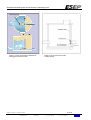
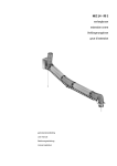
USER MANUAL FOR:
Stainless Steel (Vortex Flow) Controls
08-2012-05-Wervelventielen en debietbegrenzer
UCY series, CY series, CE/V series, OP series
Gebruikershandleiding RVS wervelventielen & debietbegrenzer
USER MANUAL FOR:
Stainless Steel (Vortex Flow) Controls
UCY series, CY series, CE/V series, OP series
ESEP Milieutechniek BV
Productgroep
Versie
08
08-2012-11-Vortex Flow Controls
2 van 8
Subject to changes – all rights reserved
ESEP Milieutechniek B.V. | NL: P.O. Box 10069
| BE: P.O. Box 7
Celsiusstraat 20
6003 DG Weert
Nederland
Tel: +31(0)495-543430
Fax: +31(0)495-532135
E-mail: [email protected]
Internet: www.esep.nl
6000 GB Weert
3945 Ham
T: +31 495 543 430
T: +32 11 241 649
F: +31 495 532 135
F: +32 11 2426 30
[email protected]
www.esep.nl
Gebruikershandleiding RVS wervelventielen & debietbegrenzer
Preface
This user manual is written according to NEN 5509 user manuals and is intended for the installer and or user
of the ESEP stainless steel (Vortex) Flow Controls. This manual is written for the easy installment, start-up,
use and maintenance of the ESEP Flow Controls. This manual should be read carefully before installment
and use and to be archived together with the relevant calculation and drawings.
Content
Preface .............................................................................................................................................. 3
Content .............................................................................................................................................. 3
Introduction........................................................................................................................................ 3
1
Identification ............................................................................................................................ 4
2
Product Specifications ............................................................................................................ 4
3
Safety ...................................................................................................................................... 4
4
Transport and storage ............................................................................................................. 5
5
Installation ............................................................................................................................... 5
6
Maintenance ............................................................................................................................ 7
7
Guarantee ............................................................................................................................... 7
8
Malfunctions ............................................................................................................................ 8
Introduction
The ESEP Stainless Steel (Vortex) Flow Control is a device intended for the restriction of (waste) water flows
in sewer systems by using the water height at the inlet level. The flow control is suitable to restrict the flow of
waste water in overflow systems, storm water systems, storage systems, combined systems, and rainwater
systems to a predetermined maximum flow capacity. The flow control consists out of a durable stainless steel
AISI 316 housing without any moving parts.
The stainless steel flow control can be divided into two different types: the cyclone type and a vertical type.
The vertical type can also be removed.
The flow control series OP, is used as a restriction for larger (waste) water flows combined with a relative low
water head. By varying the actual opening size the capacity can be precisely determined. A cable or pole can
be used to remove the plate from the housing.
3 van 8
Subject to changes – all rights reserved
ESEP Milieutechniek B.V. | NL: P.O. Box 10069
| BE: P.O. Box 7
6000 GB Weert
3945 Ham
T: +31 495 543 430
T: +32 11 241 649
F: +31 495 532 135
F: +32 11 2426 30
[email protected]
www.esep.nl
Gebruikershandleiding RVS wervelventielen & debietbegrenzer
1
Identification
This manual is only valid for the following Vortex Flow Controls:
CE/V series
UCY series
CY series
OP series
Example product identification: U CY 250 L S 190
U
= U-shaped inlet
CY = cyclone model
250 = diameter Flow Control
L
= left inlet
S190 = nominal connection diameter spigot
The producer of these Flow Control is:
ESEP Milieutechniek BV
ESEP Milieutechniek BV
Postbus 10069
Postbus 7
6003 DG Weert
3945 Ham
Netherlands
Belgium
Tel: +31(0)495-543430
Tel: +32(0)11-241649
Fax: +31(0)495-532135
Fax: +32(0)11-242630
E-mail: [email protected]
Internet: www.esep.nl
2
Product Specifications
A stainless steel Vortex Flow Control consists out of a cyclone like body suited with a specific inlet and outlet.
An OP Flow Control consists out of a removable orifice plate. Other specifications and constructional details
of the mentioned Flow Controls can also be downloaded from our website: www.esep.nl.
Assuming correct installation and normal usage the minimum lifespan of a Flow Control should be at least 10
years. That is to say that the Flow Controls will yield there effective operation until that time. The maximum
lifespan will be reduced if the Flow Control is not used or installed as described in this manual or under
extreme circumstances.
Optionally the Flow Control can be fitted with an integrated bypass system. This system will assure a full
bypass of the wastewater in the case of blockage in the Flow Control. This bypass system can be operated by
means of a manual pulling cord which is to be fitted just below the manhole.
3
Safety
The following safety precautions should be followed at all times:
a. Fire, open flames and smoking within a radius of 15 meters is strictly prohibited due to the possible
presence of explosive vapors.
b. Never enter a sewer pit alone for installation prepuces. When installing or inspecting a Flow Control this
should be done by at least two persons. Before entering a sewer pit a gas/oxygen measurement should
be executed according to the relevant local norms and regulations. Further breathing equipment should
be available.
c. Use safety gloves for protection.
d. Manhole covers should only be opened for inspection and maintenance purposes and should never be
left unattended.
e. Use safety shoes according to the relevant norms.
4 van 8
Subject to changes – all rights reserved
ESEP Milieutechniek B.V. | NL: P.O. Box 10069
| BE: P.O. Box 7
6000 GB Weert
3945 Ham
T: +31 495 543 430
T: +32 11 241 649
F: +31 495 532 135
F: +32 11 2426 30
[email protected]
www.esep.nl
Gebruikershandleiding RVS wervelventielen & debietbegrenzer
4
Transport and storage
Storage of Flow Controls should be in a stable and protected environment. External influences like bumping
should be avoided at all times. The Flow Controls should be secured firmly during transport.
5
Installation
Always check if the order is delivered completely.
When installing the Flow Control the following (safety) guidelines should be followed at all times:
a. Remove all packaging materials like pallets, plastic foals, steel wires etc. before installing the Flow
Control.
b. Position the Flow Control in such a way that its function is optimally used. The upstream waste water is
to be guided through a channel in such a way that the waste water is adequately directed towards the
inlet. This channeling should be constructed without any sharp edges to make sure the dry weather flow
is guided towards the inlet. (see also figure 1)
c.
The internal dimensions of the pit and the manhole should be wide enough to install the Flow Control
and to construct the channeling.
d. If there are any objects within the sewer pit or system that can possibly damage the Flow Control these
should be removed before bringing the Flow Control in to use.
e. The Flow Controls can be installed in several ways:
1:
The outlet of a cyclone like Flow Control is positioned into the outlet of a sewer
pit. This is possible by inserting part of the cyclone or the prefabricated spigot into the
concrete wall. Then the Flow Control should be poured into the channeling concrete
and by doing so will be securely fastened. The concrete channeling should be
minimally poured until the top of the U-shaped inlet or covering 1/3 of the cyclone
diameter in such a way that the identification plate is not covered.
2:
The Flow Controls OP and CE/V series are installed by a mounting plate against
the outlet of the sewer pit. A minimum space of 40 centimeters is to be preserved
underneath the outlet. When the concrete wall is not completely flat a kit or rubber seal
should be inserted between the plate and the wall.
f.
The upstream and downstream sewer pipes should have an adequate flow and no deficiencies.
g. Due to the Vortex Flow effect the water at the outlet can create corrosion to the sewer pit or piping. If this
is the case, protective measures should be taken to prevent this.
h. It is highly advisable to position a penstock valve next to the flow control in the overflow wall to provide a
bypass opportunity in the case of blockage.
Incorrect installation will affect the performance of the Flow Control. Incorrect installation or use for other
purposes than intended will not be covered by the guarantee conditions.
Always check if all the manhole covers are securely closed to prevent any accidents.
5 van 8
Subject to changes – all rights reserved
ESEP Milieutechniek B.V. | NL: P.O. Box 10069
| BE: P.O. Box 7
6000 GB Weert
3945 Ham
T: +31 495 543 430
T: +32 11 241 649
F: +31 495 532 135
F: +32 11 2426 30
[email protected]
www.esep.nl
Gebruikershandleiding RVS wervelventielen & debietbegrenzer
Stroomprofiel
Figure 1; Flow control with overflow wall
and bypass penstock valve.
Figure 2; Flow control OP-series
or CE/V-series.
6 van 8
Subject to changes – all rights reserved
ESEP Milieutechniek B.V. | NL: P.O. Box 10069
| BE: P.O. Box 7
6000 GB Weert
3945 Ham
T: +31 495 543 430
T: +32 11 241 649
F: +31 495 532 135
F: +32 11 2426 30
[email protected]
www.esep.nl
Gebruikershandleiding RVS wervelventielen & debietbegrenzer
6
Maintenance
The following safety precautions should be followed at all times:
a. Fire, open flames and smoking within a radius of 15 meters is strictly prohibited due to the possible
presence of explosive vapors.
b. To make sure the Flow Control is working correctly frequent inspection is necessary. Specially shortly
after installation frequent inspection should take place also depending on the nature and quantity of
existing pollution.
c.
Any damages or deficiencies that are observed during inspections should be repaired immediately. Small
reparations can be done at the site, more complex reparations should be done by a specialized
mechanic. All damages or deficiencies should be communicated in writhing within 24 hours to ESEP
Milieutechniek according to our guarantee conditions.
d. Never enter a sewer pit alone!
7
Guarantee
The guarantee on Flow Controls is 1 year according to the relevant specifications starting from the date of
delivery. In the case of a proven deficiency on a ESEP Flow Control the customer is entitled to repair or
replacement of the goods delivered. This is only valid when the goods have been used for their intended
purposes and in normal circumstances. Further the customer should have complied with all guidelines in this
manual, correct maintenance and communicating any deficiencies within the time specified.
All rights to damage compensation like lost income, consequential damages, direct or indirect, as a result of
using the deficient goods are excluded. All goods that are installed by the customer are assumed to have
been accepted in good order.
Any changes to the delivered goods without prior written consent of ESEP will forfeit the guarantee. All used
products and accessories should be approved by ESEP.
See for detailed guarantee conditions our general terms of sales as provided at the time of the order.
7 van 8
Subject to changes – all rights reserved
ESEP Milieutechniek B.V. | NL: P.O. Box 10069
| BE: P.O. Box 7
6000 GB Weert
3945 Ham
T: +31 495 543 430
T: +32 11 241 649
F: +31 495 532 135
F: +32 11 2426 30
[email protected]
www.esep.nl
Gebruikershandleiding RVS wervelventielen & debietbegrenzer
8
Malfunctions
In the malfunction table some malfunctions are described with their possible solutions.
Malfunction
1. No watersupply
Possible cause
A. Check the incoming pipe for blockage
B. Check the fall of the incoming pipe
Solution
A. Deblock the pipe
B. Create fall in the pipe
2. No discharge
A. Check the outgoing pipe for blockage
B. Check the Flow Control for blockage
C. Check the watersupply
A. Deblock the pipe
B. Empty the pit and check the Flow
Control for blockages
C. See malfunction 1
A. See malfunction 2
3. High waterlevel
A. Check the discharge
Table 1 – Malfunction table
8 van 8
Subject to changes – all rights reserved
ESEP Milieutechniek B.V. | NL: P.O. Box 10069
| BE: P.O. Box 7
6000 GB Weert
3945 Ham
T: +31 495 543 430
T: +32 11 241 649
F: +31 495 532 135
F: +32 11 2426 30
[email protected]
www.esep.nl