1
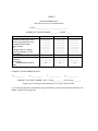
Grid Interconnection & Contract Development Request for Payment Instructions Wholesale Distribution Access Tariff (WDAT) Attachment I - GIP Submittal Instructions Prior to submitting your application and fee or deposit, please complete and submit this form to: [email protected] In response, you will receive detailed payment instructions within a Request for Advance Payment form that will greatly facilitate the tracking and processing of your request. The Request for Advance Payment form will contain mailing and wiring instructions along with a document number for SCE to track your payment. Please do not mail any checks along with your interconnection application, instead, please use the instructions provided. Absent extraordinary circumstances, instructions should be sent to you within 3 business days of receipt of this completed Request for Payment Instructions form. Once the payment confirmation and complete application package are received, your request will be forwarded for processing and review. INTERCONNECTION CUSTOMER INFORMATION Customer Name: Customer Address: Project Contact Name: Project Contact Phone Number: E-mail: Project Name: New Project Generating Facility Gross Nameplate Rating (In MW): INTERCONNECTION STUDY PROCESS Select the one study processes listed below: Cluster Study Process – “Interconnection Study Deposit equal to $50,000 plus $1,000 per MW of electrical output of the Generating Facility, or the increase in electrical output of the existing Generating Facility, as applicable, rounded up to the nearest whole megawatt, up to a maximum of $250,000” * Site Exclusivity - Check here if you will be submitting a “posting of a Site Exclusivity Deposit of $100,000* for a Small Generating Facility or $250,000* for a Large Generating Facility.” (Refer to section 4.2.1 of the WDAT Attachment I) Independent Study Process (ISP) – “Interconnection Study Deposit equal to $50,000 plus $1,000 per MW of electrical output of the Generating Facility, or the increase in electrical output of the existing Generating Facility, as applicable, rounded up to the nearest whole megawatt, up to a maximum of $250,000” * Fast Track Process – “The Interconnection Customer shall submit its Interconnection Request to the Distribution Provider, together with a non-refundable processing fee of $500 and a non-refundable study deposit of $1,000.” * Other (specify) – __________________________________________________________________________________ WHOLESALE DISTRIBUTION SERVICE REQUEST “An Eligible Customer requesting service under the Tariff must submit an Application, with a deposit of $2.00 per anticipated average monthly kilowatts of Generation or Wholesale Distribution Load, to the Distribution Provider as far as possible in advance of the month in which service is to commence.” (Section 15.2 of the Wholesale Distribution Access Tariff) Anticipated average monthly kilowatts of Generation or Wholesale Distribution Load for your proposed project: __________ SCE GRID INTERCONNECTION CONTACT INFORMATION If you have any questions, please contact us: Via E-mail: [email protected] The Grid Interconnection phone number is: 626-302-3688 *Fees and deposits are calculated using the Wholesale Distribution Access Tariff, section15.2, as well as Attachment I (also known as the GIP) Section 4 for the Cluster Study Process, Section 5 for the Independent Study Process, and section 6 for the Fast Track process. Please refer to the tariff for the most current fee and deposit information as well as refund guidelines. A copy of the Wholesale Distribution Access Tariff can be found on our Open Access site: www.sce.com/GridInterconnection Southern California Edison Company as of 02/22/2013 Wholesale Distribution Access Tariff Effective Date: 12/08/2012 FERC Docket: ER13-00532-000 434 FERC Order: BOL Status: Order Date: Effective 02/11/2013 APPENDIX 1 to GIP WHOLESALE DISTRIBUTION ACCESS TARIFF INTERCONNECTION REQUEST FOR A GENERATING FACILITY Provide two copies of this completed form pursuant to Section 7 of this GIP Appendix 1 below. 1. The undersigned Interconnection Customer submits this request to interconnect its Generating Facility with Distribution Provider's Distribution System pursuant to the following process under Appendix I of the Tariff (check only one): Cluster Study Process Independent Study Process Fast Track Process Other (specify)_____________________________________________________ 2. This Interconnection Request is for (check only one): A proposed new Generating Facility. An increase in the generating capacity or a Material Modification of an existing Generating Facility. A change to Full Capacity Deliverability Status for a Generating Facility previously studied as Energy Only Deliverability Status in accordance with Section 4.7 of the GIP (Full Capacity Deliverability Study). 3. Deliverability Study is performed by the ISO. Requested Deliverability Status is for (check only one): Full Capacity Deliverability Status (this option applies to the Cluster Study Process and Independent Study Process only) Partial Capacity Deliverability Status for ____ MW [specify requested MW to be evaluated for Deliverability. This MW amount should be less than the total MW of the Generating Facility) of electrical output (this option applies to the Cluster Study Process and Independent Study Process only) Energy Only Deliverability Status (this option applies to the Cluster Study Process, Independent Study Process, and Fast Track Process) 4. Interconnection Customer provides the following information: a. Address or location, including the county, of the proposed new Generating Facility site (to the extent known) or, in the case of an existing Generating Facility, the name and specific location, including the county, of the existing Generating Facility; Project Name: ______________________________________ Project Location: __________________________________________ Street Address: _____________________________________ City, State: ___________________, ___________________ County: ______________________________________ Zip Code: ____________________ GPS Coordinates: ______________________________ b. Maximum net megawatt electrical output (as defined by section 2.c. of Attachment A to this appendix) of the proposed new Generating Facility or the amount of net megawatt increase in the generating capacity of an existing Generating Facility; Maximum net megawatt electrical output (MW): ________ Net Megawatt increase (MW): ________ c. Type of project (i.e., gas turbine, hydro, wind, etc.) and general description of the equipment configuration (if more than one type is chosen, include net MW for each); d. or Cogeneration _____ MW Reciprocating Engine _____ MW Biomass _____ MW Steam Turbine _____ MW Gas Turbine _____ MW Wind _____ MW Hydro _____ MW Inverter Based: _____ MW (e.g., Photovoltaic, Fuel Cell) If Fuel Cell, please describe primary fuel source: _______ Combined Cycle _____ MW Other: _____ MW (Please describe):_______________________________________ Proposed In-Service Date, and Other Key Dates (Month/Day/Year) (Dates must be sequential) Requested Back-Feed Date Proposed In-Service Date: Proposed Trial Operation Date: Proposed Commercial Operation Date: ____/____/____ ____/____/____ ____/____/____ ____/____/____ Proposed Term of Service (years): ________ e. Name, address, telephone number, and e-mail address of Interconnection Customer's contact person (primary person who will be contacted); Name: ______________________________________ Title: ______________________________________ Company Name: ______________________________________ Street Address: ______________________________________ City, State: ___________________, ___________________ Zip Code: ___________________ Phone Number: ___________________ Fax Number: ___________________ Email Address: ___________________ Interconnection Customer’s DUNS Number: ___________________ f. Point of Interconnection: Distribution Substation (Name and voltage level): ______________________, or Distribution Feeder: ______________________________________________, or Approximate location of the proposed Point of Interconnection: Distribution Facility Interconnection Point Name: __________________ Voltage Level _______________ Proposed Location of Interconnection: ____________________________ g. Interconnection Customer Data (set forth in Attachment A) The Interconnection Customer shall provide to the Distribution Provider the technical data called for in Attachment A. Two (2) copies are required. 5. Applicable Interconnection Study Deposit amount as specified in GIP Section 4.2.1 or 4.7.1, as applicable, for the Cluster Study Process or GIP Section 5.2.1 for the Independent Study Process, or $1,500 as provided in GIP Section 6.2 for the Fast Track Process made payable to Southern California Edison Company. Send check to Distribution Provider along with: 1. A completed Interconnection Request form for processing. 2. A completed Attachment A (Interconnection Request Generating Facility Data). 6. Evidence of Site Exclusivity as specified in GIP Sections 4.2.1, 5.2.1, or 6.3, as applicable, and name(s), address(es) and contact information of site owner(s). Check one. Is attached to this Interconnection Request If Interconnection Customer requests processing under the Cluster Study Process, then deposit in lieu of Site Exclusivity attached. Site Exclusivity will be provided at a later date in accordance with this GIP. 7. This Interconnection Request shall be submitted to the representative indicated below: Southern California Edison Company Director of FERC Policy & Contracts P.O. Box 800 Rosemead, CA 91770 Overnight address: 2244 Walnut Grove Avenue, Rosemead, CA 91770 8. Representative of Interconnection Customer to contact: [To be completed by Interconnection Customer] Name: ______________________________________ Title: ______________________________________ Company Name: ______________________________________ Street Address: ______________________________________ City, State: ___________________, ___________________ Zip Code: ___________________ Phone Number: ___________________ Fax Number: ___________________ Email Address: ___________________ 9. If the Interconnection Customer also requests Distribution Service, additional information and an additional deposit is required in accordance with Section 15.2 of the Tariff. 10. This Interconnection Request is submitted by: Legal name of Interconnection Customer: ___________________________________ By (signature): ____________________________________________________ Name (type or print): _______________________________________________ Title: ____________________________________________________________ Date: ___________________ Attachment A to Interconnection Request WHOLESALE DISTRIBUTION ACCESS TARIFF GENERATING FACILITY DATA Provide two copies of this completed form pursuant to Section 7 of Interconnection Request. Each Interconnection Customer will complete Sections 1 and 2 of this Attachment A. Each Interconnection Customer will complete the applicable data in Sections 3 through 6 of this Attachment A based on the type of generating facility(ies) requesting interconnection. (Section 3 for synchronous generators, Section 4 for induction generators, Section 5 for wind turbine generators, and Section 6 for inverter-based generators). Each Interconnection Customer will complete Sections 7 through 10, as applicable. At any time, Distribution Provider may require Interconnection Customer to provide additional technical data, or additional documentation supporting the technical data provided, as deemed necessary by the Distribution Provider to perform Interconnection Studies, other studies, or evaluations as set forth under the GIP. 1. Provide two original prints and one reproducible copy (no larger than 36” x 24”) of the following: A. B. 2. Site drawing showing generator location and Point of Interconnection with the Distribution Provider’s Distribution System. Single-line diagram showing applicable equipment such as generating units, stepup transformers, auxiliary transformers, switches/disconnects of the proposed interconnection, including the required protection devices and circuit breakers. This one-line drawing must be signed and stamped by a licensed Professional Engineer if the Generating Facility is larger than 50 kW. Generating Facility General Information: A. Total Generating Facility rated output (MW): _______________ B. Generating Facility auxiliary Load (MW): _______________ C. Project net capacity (MW): _______________ D. Standby Load when Generating Facility is off-line (MW): _______________ E. Number of Generating Units: ___________________ (Please repeat the following items for each generator) F. Individual generator rated output (MW for each unit): ______________________ G. Manufacturer of the Generating Facility: ________________________________ H. Year Manufactured: ____________ I. Nominal Terminal Voltage (kV): ______________________________ J. Rated Power Factor (%): _____________ K. Type (induction, synchronous, D.C. with inverter): ________________________ L. Phase (3 phase or single phase): _______ M. N. O. P. 3. Connection (Delta, Grounded WYE, Ungrounded WYE, impedance grounded): __________________________________________ Generator Voltage Regulation Range (+/- %): _____________ Generator Power Factor Regulation Range: _____________ For combined cycle plants, specify the plant net output capacity (MW) for an outage of the steam turbine or an outage of a single combustion turbine______________ Synchronous Generator -Information: 3A Generator Information: (Please repeat the following for each generator) A. B. C. D. E. F. G. H. I. J. 3B Rated Generator speed (rpm): ____________ Rated MVA: _______________ Rated Generator Power Factor: ____________ Generator Efficiency at Rated Load (%): ____________ Moment of Inertia (including prime mover): ____________ Inertia Time Constant (on machine base) H: ____________ sec or MJ/MVA SCR (Short-Circuit Ratio - the ratio of the field current required for rated open-circuit voltage to the field current required for rated short-circuit current): ___________________________________________ Please attach generator reactive capability curves. Rated Hydrogen Cooling Pressure in psig (Steam Units only): ________________________________________________ Please attach a plot of generator terminal voltage versus field current that shows the air gap line, the open-circuit saturation curve, and the saturation curve at full load and rated power factor. Excitation System Information: (Please repeat the following for each generator) A. Indicate the Manufacturer ____________________ and Type _____________of excitation system used for the generator. For exciter type, please choose from 1 to 9 below or describe the specific excitation system. (1) Rotating DC commutator exciter with continuously acting regulator. The regulator power source is independent of the generator terminal voltage and current. (2) Rotating DC commentator exciter with continuously acting regulator. The regulator power source is bus fed from the generator terminal voltage. (3) Rotating DC commutator exciter with non-continuously acting regulator (i.e., regulator adjustments are made in discrete B. C. D. E. F. 3C Power System Stabilizer (“PSS”) Information: (Please repeat the following for each generator model. All new generators are required to install PSS unless an exemption has been obtained from WECC. Such an exemption can be obtained for units that do not have suitable excitation systems.) A. B. C. D. E. 3D increments). (4) Rotating AC Alternator Exciter with non-controlled (diode) rectifiers. The regulator power source is independent of the generator terminal voltage and current (not bus-fed). (5) Rotating AC Alternator Exciter with controlled (thyristor) rectifiers. The regulator power source is fed from the exciter output voltage. (6) Rotating AC Alternator Exciter with controlled (thyristor) rectifiers. (7) Static Exciter with controlled (thyristor) rectifiers. The regulator power source is bus-fed from the generator terminal voltage. (8) Static Exciter with controlled (thyristor) rectifiers. The regulator power source is bus-fed from a combination of generator terminal voltage and current (compound-source controlled rectifiers system. (9) Other (specify): _______________________________________ Attach a copy of the block diagram of the excitation system from its instruction manual. The diagram should show the input, output, and all feedback loops of the excitation system. Excitation system response ratio (ASA): ______________ Full load rated exciter output voltage: ___________ Maximum exciter output voltage (ceiling voltage): ___________ Other comments regarding the excitation system? ___________________ ____________________________________________________________ Manufacturer: _____________________________________________ Is the PSS digital or analog? __________________________________ Note the input signal source for the PSS? Bus frequency _____ Shaft speed _____ Bus Voltage _____________________ Other (specify source) _____________________ Please attach a copy of a block diagram of the PSS from the PSS Instruction Manual and the correspondence between dial settings and the time constants or PSS gain. Other comments regarding the PSS? ____________________________________________________________ Turbine-Governor Information: (Please repeat the following for each generator model.) Please complete Part A for steam, gas or combined-cycle turbines, Part B for hydro turbines, and Part C for both. A. Steam, gas or combined-cycle turbines: (1) (2) (3) (4) B. Hydro turbines: (1) (2) (3) (4) (5) (6) (7) (8) C. Turbine efficiency at rated load: _______% Length of penstock: ______ft Average cross-sectional area of the penstock: _______ft2 Typical maximum head (vertical distance from the bottom of the penstock, at the gate, to the water level): ______ft Is the water supply run-of-the-river or reservoir: ___________ Water flow rate at the typical maximum head: _________ft3/sec Average energy rate: _________kW-hrs/acre-ft Estimated yearly energy production: ________kW-hrs Complete this section for each machine, independent of the turbine type. (1) (2) (3) (4) 3E List type of unit (Steam, Gas, or Combined-cycle):__________ If steam or combined-cycle, does the turbine system have a reheat process (i.e., both high and low pressure turbines)? _______ If steam with reheat process, or if combined-cycle, indicate in the space provided, the percent of full load power produced by each turbine: Low pressure turbine or gas turbine:______% High pressure turbine or steam turbine:______% For combined cycle plants, specify the plant net output capacity (MW) for an outage of the steam turbine or an outage of a single combustion turbine:_____________________________________ Turbine manufacturer: _______________ Maximum turbine power output: _______________MW Minimum turbine power output (while on line): _________MW Governor information: (a) Droop setting (speed regulation): _____________ (b) Is the governor mechanical-hydraulic or electro-hydraulic (Electro-hydraulic governors have an electronic speed sensor and transducer.)? _________________ (c) Other comments regarding the turbine governor system? ______________________________________________ Short Circuit Duty Information: For each generator, provide the following reactances expressed in p.u. on the generator base: • • • • • Xd - Direct Axis Synchronous Reactance: _____ p.u. X’d - Direct Axis Transient Reactance: _____ p.u. X”d - Direct Axis Subtransient Reactance: _____ p.u. X2 - Negative Sequence Reactance: _____ p.u. X0 - Zero Sequence Reactance: _____ p.u. Generator Grounding (select one for each model): A. B. C. 4. Induction Generator Information: (Please repeat the following for each generator) A. B. C. D. E. F. G. H. I. J. K. L. M. N. O. 5. _____ Solidly grounded _____ Grounded through an impedance (Impedance value in p.u. on generator base. R:_____________p.u. X:_____________p.u.) _____ Ungrounded Motoring Power (kW): ______________ I22t or K (Heating Time Constant): ______________ Rotor Resistance, Rr: ______________ Stator Resistance, Rs: ______________ Stator Reactance, Xs: ______________ Rotor Reactance, Xr: ______________ Magnetizing Reactance, Xm: ______________ Short Circuit Reactance, Xd'': ______________ Exciting Current: ______________ Temperature Rise: ______________ Frame Size: ______________ Design Letter: ______________ Reactive Power Required In Vars (No Load): ______________ Reactive Power Required In Vars (Full Load): ______________ Total Rotating Inertia, H: _____________ Per Unit on kVA Base Wind Turbine Generator (WTG) Information: (Proposed projects may include one or more WTG types. Please repeat the following for each type of WTG). A. Number of generators to be interconnected pursuant to this Interconnection Request: _____ B. Average Site Elevation: ______ Single Phase _____ Three Phase_____ C. Field Volts: _________________ D. Field Amperes: ______________ E. Motoring Power (MW): _______ F. G. H. I. J. K. L. M. N. O. P. Q. R. S. T. Neutral Grounding Resistor (If Applicable): ____________ I22t or K (Heating Time Constant): ____________ Rotor Resistance: ____________ Stator Resistance: ____________ Stator Reactance: ____________ Rotor Reactance: ____________ Magnetizing Reactance: ___________ Short Circuit Reactance: ___________ Exciting Current: ________________ Temperature Rise: ________________ Frame Size: _______________ Design Letter: _____________ Reactive Power Required In Vars (No Load):________ Reactive Power Required In Vars (Full Load):________ Total Rotating Inertia, H: ________ Per Unit on 100 MVA Base Note: A completed General Electric Company Power Systems Load Flow (PSLF) data sheet must be supplied with the Interconnection Request. If other data sheets are more appropriate to the proposed device then they shall be provided and discussed at Scoping Meeting. Distribution Provider may require testing verification of voltage and harmonic performance during commissioning test of WTG based generation projects. 6. Inverter Based Generation Systems Information: (Proposed inverter based generation projects may include one or more types of inverters. Please repeat the following for each type of inverter). A. B. C. D. E. F. G. H. I. J. Inverter Manufacturer and Model: _________________________ Number of Inverters: ___________________ Nameplate Rating (AC, each inverter): _______/_______ kW Nameplate Voltage Rating (AC): _______ kV Maximum AC line current: _______ Amps Nameplate Power Factor Rating (AC): _______ Please attach capability curve describing reactive power or power factor range from no output to full rated output Inverter control mode (e.g. voltage, power factor, reactive power): _______ Short Circuit Characteristics: Applicant to provide technical data related to the short circuit characteristics of proposed inverter based generation systems. For example, the applicant can provide a sinusoidal waveform test data showing faulted condition at the AC side of the inverter for a three phase and single-lineto-ground fault. Harmonics Characteristics: (1) Inverter switching frequency: _______ (2) Harmonic characteristics for each unit up to switching frequency: _______ K. (3) Harmonic characteristics for aggregate generation facility: _______ Inverter disconnection characteristics: Applicant to provide voltage sinusoidal waveform test data which shows the voltage characteristics during disconnection of inverter system from distribution system at 100% and at 50% of rated output. Distribution Provider may require testing verification of voltage and harmonic performance during commissioning test of the inverter based generation systems. 7. Step-Up Transformer Data: For each step-up transformer (e.g. main step-up transformers, padmount transformers), fill out the data form provided in Table 1. 8. Interconnection Facilities Line Data: For transmission lines that are to be planned by the generation developer, please provide the following information: Nominal Voltage: _______________ kV Line Length (miles): ___________________ Line termination Points: ___________________ Conductor Type: ______ Size: ________ If bundled. Number per phase: ______, Bundle spacing: _____in. Phase Configuration. Vertical: _______, Horizontal: _______ Phase Spacing (ft): A-B: ______, B-C: _______, C-A: ________ Distance of lowest conductor to Ground at full load and 40°C: _________ft Ground Wire Type: ________ Size: _______ Distance to Ground: ______ft Attach Tower Configuration Diagram Summer line ratings in amperes (normal and emergency) _________________ Positive Sequence Resistance ( R ): __________ p.u.** (for entire line length) Positive Sequence Reactance: ( X ): __________ p.u.** (for entire line length) Zero Sequence Resistance ( R0 ): __________ p.u.** (for entire line length) Zero Sequence Reactance: ( X0 ): __________ p.u.** (for entire line length) Line Charging (B/2): __________ p.u.** ** On 100-MVA and nominal line voltage (kV) Base 9. Plant-Level Reactive Power Compensation Data: Provide the following information for plant-level reactive power compensation, if applicable: A. B. C. Number of individual shunt capacitor banks: _____________ Individual shunt capacitor bank rated voltage (kV): _____________ Individual shunt capacitor bank size (kVAR at rated voltage): _____________ D. E. F. G. 10. Planned dynamic reactive control devices (SVC, STATCOM): _____________ Control range: _____________ kVAR (lead) _____________ kVAR (lag) Control mode (e.g. voltage, power factor, reactive power): _____________ Please provide the overall plant reactive power control strategy Load Flow and Dynamic Models: The WECC Data Preparation Manual for Power Flow Base Cases and Dynamic Stability Data has established power flow and dynamic modeling requirements for generation projects in WECC base cases. In general, if the aggregate sum of generation on a bus exceeds 10 MVA, it should not be netted. Furthermore, the total netted generation in an area should not exceed five percent of the area’s total generation. Based on current WECC modeling requirements, the following information will be required for all generation projects whose net capacity is greater than 10 MVA. The following information may also be required for generation projects less than 10 MVA on a case-by-case basis, based on the amount of generation in the area of the requested Point of Interconnection. A. Provide load flow model for the generating plant and its interconnection facilities in GE PSLF *.epc format, including new buses, generators, transformers, interconnection facilities. An equivalent model is required for the plant with generation collector systems. This data should reflect the technical data provided in this Attachment A. B. For each generator, governor, exciter, power system stabilizer, WTG, or inverter based generator, select the appropriate dynamic models from the General Electric PSLF Program Manual and provide the required input data. Include any user written *.p EPCL files to simulate inverter based plants’ dynamic responses (typically needed for inverter based PV/wind plants). Provide a completed *.dyd file that contains the information specified in this section. The GE PSLF manual is available upon request from GE. There are links within the GE PSLF User’s Manual to detailed descriptions of specific models, a definition of each parameter, a list of the output channels, explanatory notes, and a control system block diagram. In addition, GE PSLF modeling information and various modeling guidelines documents have been prepared by the WECC Modeling and Validation Work Group. This information is available on the WECC website (www.wecc.biz). If you require assistance in developing the models, we suggest you contact General Electric. Accurate models are important to obtain accurate study results. Costs associated with any changes in facility requirements that are due to differences between model data provided by the generation developer and the actual generator test data, may be the responsibility of the generation developer. TABLE 1 TRANSFORMER DATA (Provide for each level of transformation) UNIT*_____________________________________ NUMBER OF TRANSFORMERS_________ PHASE _______ RATING Rated MVA Connection (Delta, Wye, Gnd.) Cooling Type (OA,OA/FA, etc) : Temperature Rise Rating Rated Voltage BIL Available Taps (% of rating) Load Tap Changer? (Y or N) Tap Settings IMPEDANCE Percent MVA Base Tested Taps WINDING RESISTANCE Ohms H Winding __________ __________ __________ __________ __________ __________ __________ __________ __________ H-X ___________ ___________ __________ H __________ X Winding __________ __________ __________ __________ __________ __________ __________ __________ __________ H-Y __________ __________ __________ X __________ Y Winding __________ __________ __________ __________ __________ __________ __________ __________ __________ X-Y __________ __________ __________ Y __________ CURRENT TRANSFORMER RATIOS H_____________ X______________ Y______________ N_____________ PERCENT EXCITING CURRENT 100 % Voltage; _________ 110% Voltage________ Supply copy of nameplate and manufacturer’s test report when available. * For Generating Facilities with multiple step-up transformers, identify the transformer datasheet unit number with that of the single line.