1
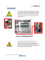
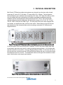
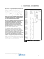
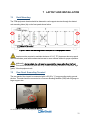
ZTM-Series Modular Test Systems User’s Manual This document and its contents are the property of Mini-Circuits 1 Important Notice This guide is owned by Mini-Circuits and is protected by copyright, trademark and other intellectual property laws. The information in this guide is provided by Mini-Circuits as an accommodation to our customers and may be used only to promote and accompany the purchase of Mini-Circuits’ Parts. This guide may not be reproduced, modified, distributed, published, stored in an electronic database, or transmitted and the information contained herein may not be exploited in any form or by any means, electronic, mechanical recording or otherwise, without prior written permission from Mini-Circuits. This guide is subject to change, qualifications, variations, adjustments or modifications without notice and may contain errors, omissions, inaccuracies, mistakes or deficiencies. Mini-Circuits assumes no responsibility for, and will have no liability on account of, any of the foregoing. Accordingly, this guide should be used as a guideline only. Trademarks Microsoft, Windows, Visual Basic, Visual C# and Visual C++ are registered trademarks of Microsoft Corporation. LabVIEW and CVI are registered trademarks of National Instruments Corporation. Delphi is a registered trademark of Delphi Technologies, Inc. MATLAB is a registered trademark of The MathWorks, Inc. Agilent VEE is a registered trademark of Agilent Technologies, Inc. Linux is a registered trademark of Linus Torvalds. Mac is a registered trademark of Apple Inc. Python is a registered trademark of Python Software Foundation Corporation. All other trademarks cited within this guide are the property of their respective owners. Neither MiniCircuits nor the Mini-Circuits ZTM Series Modular Test Systems are affiliated with or endorsed or sponsored by the owners of the above referenced trademarks. Mini-Circuits and the Mini-Circuits logo are registered trademarks of Scientific Components Corporation. Mini-Circuits 13 Neptune Avenue Brooklyn, NY 11235 Phone: 1-718-934-4500 Email: [email protected] Web: www.minicircuits.com Version 4/10/15 © Mini-Circuits, 2015. All rights reserved. This document and its contents are the property of Mini-Circuits 2 CONTENTS 1 INTRODUCTION ................................................................................................................... 4 2 WARNINGS ........................................................................................................................... 5 2.1 Safety Hazards .............................................................................................................. 5 2.2 Additional Precautions ................................................................................................... 6 3 PHYSICAL DESCRIPTION.................................................................................................... 7 4 FUNCTIONAL DESCRIPTION............................................................................................... 8 5 PERFORMANCE SPECIFICATIONS .................................................................................... 9 5.1 DC Power Specifications ............................................................................................... 9 5.2 RF Specifications ........................................................................................................... 9 6 UNPACKING ........................................................................................................................10 6.1 Unpacking ....................................................................................................................10 6.2 Package Contents ........................................................................................................10 7 LAYOUT AND INSTALLATION.............................................................................................11 7.1 Rack Mounting..............................................................................................................11 7.2 Rear Panel Grounding Terminal ...................................................................................11 8 SOFTWARE .........................................................................................................................12 8.1 Software Overview .......................................................................................................12 8.2 Installing Mini-Circuits’ GUI Software ............................................................................12 8.3 Connecting to the Hardware .........................................................................................15 8.3.1 Connecting via USB............................................................................................15 8.3.2 Connecting via Ethernet .....................................................................................16 8.3.3 Demo Mode........................................................................................................17 8.4 Using the GUI Controls .................................................................................................18 8.4.1 The Main Control ................................................................................................18 8.4.2 Attenuator Sequencing .......................................................................................21 8.4.3 Direct Mode ........................................................................................................24 8.4.4 Ethernet Configuration: ......................................................................................26 8.5 Updating Firmware .......................................................................................................27 8.6 Programming Support ..................................................................................................30 9 RETURN MATERIAL AUTHORIZATION (RMA) PROCEDURE............................................31 This document and its contents are the property of Mini-Circuits 3 1 INTRODUCTION Thank you for choosing Mini-Circuits ZTM-Series modular test systems to meet your needs! The purpose of the ZTM-Series User’s Manual is to instruct you on basic installation and setup of your equipment, to advise you on general precautions to be taken when installing and handling your ZTM unit, and to provide instruction on installing and using the control software for this unit on your PC. We’re here to support you every step of the way. For technical support and assistance, please find the following points of contact for your convenience: Chi Man Shum Phone: +1 201 647-1615 Email: [email protected] [email protected] Lee Whiting +44 1252 832 620 Email: [email protected] This document and its contents are the property of Mini-Circuits 4 2 WARNINGS 2.1 Safety Hazards Electrical Danger This equipment contains live 110/220V contacts and should be used and handled only by qualified professionals. When performing any activity in and around the ZTM box, please exercise extreme caution to avoid touching any parts where live voltage may be present to prevent injury or death due to electrical shock. Figure 1: Live 110 / 220V contacts inside ZTM box. Heavy Object The equipment case for your ZTM-Series unit is heavy. When handling, use caution to prevent damage to the equipment and injury. Always follow safe lifting protocols and use any necessary lifting aids to prevent muscle strain or back injury. The unit must be supported in a rack structure by securely fastened side rails or shelving. This document and its contents are the property of Mini-Circuits 5 2.2 Additional Precautions Air Flow: The equipment chassis must be mounted by the customer to maintain a minimum of 1U (1.75”) free air space above and below the top and bottom panels with unobstructed access to room ambient airflow for proper operation. Electrostatic Discharge: Any person operating this ZTM-series unit must have Electrostatic Discharge (ESD) protection to prevent damage to any components. Opening & Tampering: This equipment is designed to be serviced only by professional electrical technicians. Case openings by any person other than qualified personnel authorized by Mini-Circuits or the customer will void any and all terms of the Limited Warranty.1 1 Although top and bottom panels are intended to allow accessibility, it is important that caution be taken when connecting or disconnecting any electrical or RF connection; moving, removing, or replacing any wires, cables, connections, switches, or other components within the chassis to avoid potentially damaging or dislodging any other cables or connections. This document and its contents are the property of Mini-Circuits 6 3 PHYSICAL DESCRIPTION Mini-Circuits’ ZTM-series modular test systems come housed in an aluminum alloy chassis measuring 19” wide x 5.22” (3U) high x 13” deep (483 x 133 x 330mm). The front panel is fabricated with six open windows, each measuring 2.43” wide x 3.35” high (62 x 85mm), which may be outfitted with many combinations of hardware according to customer preference. Hardware options include absorptive electromechanical SPDT, SP4T, SP6T and transfer switches and programmable attenuators with attenuation ranges of 0 to 30, 60, 90, 110 and 120 dB. All RF connectors are SMA-F type. The front panel of the unit is also equipped with two handles, an identification plate, and the power switch. Slotted holes on the outer left and right extensions of the front panel allow secure mounting to a standard 19” (483mm) rack support structure. Figure 2: Front panel of ZTM equipment chassis (configuration shown here for demonstration only) On the rear panel of the unit is the input for a standard 110/220V AC power supply (right side). At the bottom right of the rear panel is a clearly marked grounding terminal. It is recommended that this terminal be connected to a Common Bonding Network (CBN). On the lower left side of the rear panel are connection ports for USB and Ethernet allowing the user to communicate with the equipment from his or her PC. The identification sticker at the upper left contains the model name, serial number, and control board number. Figure 3: Rear panel of ZTM equipment chassis (model shown for demonstration only) This document and its contents are the property of Mini-Circuits 7 4 FUNCTIONAL DESCRIPTION Mini-Circuits’ ZTM-Series modular test systems are designed to simplify and accelerate the development of custom test solutions. The modular chassis structure allows a wide variety of custom hardware configurations to be built and shipped to customers within 2 weeks or less. Each hardware window may be configured with 1 SP4T or SP6T switch or up to 2 SPDT switches, transfer switches, or programmable attenuators. Hardware windows may also contain a blank plate if desired. Mini-Circuits absorptive electromechanical switches provide extra-long switching life, performance qualified to 100 million switch cycles with proper maintenance. RUDAT-series programmable attenuators provide precise level control with attenuation ranges from 0 to 30, 60, 90, 110, and 120 dB in 0.25 dB attenuation steps. The equipment may be controlled via USB or Ethernet (HTTP and Telnet Protocols), allowing setup flexibility and easy remote test management. All units come supplied with Mini-Circuits’ userfriendly Graphical User Interface (GUI) software and DLLs for 32-bit and 64-bit Windows® operating systems. Full programming support is provided for a wide range of programming environments on both Windows and Linux® operating systems, supporting control through your native test software. Figure 5: ZTM-Series Modular Test System Functional Schematic Figure 4: ZTM-series modular test system block diagram This document and its contents are the property of Mini-Circuits 8 5 PERFORMANCE SPECIFICATIONS 5.1 DC Power Specifications Supply Voltage: 110/220V Operating Current will vary based on the number and type of components in your system. 5.2 RF Specifications For RF specifications of your ZTM-series unit, please refer to the model data sheets for the individual components within your system configuration. Table 1: RF specifications for component hardware Component Model Number Link to Datasheet SPDT Switch MSP2TA-18XL+ http://www.minicircuits.com/pdfs/MSP2TA-18XL+.pdf SP4T Switch MSP4TA-18+ http://www.minicircuits.com/pdfs/MSP4TA-18+.pdf SP6T Switch MSP6TA-12+ http://www.minicircuits.com/pdfs/MSP6TA-12+.pdf Transfer Switch MTS-18XL+ http://www.minicircuits.com/pdfs/MTS-18XL-B+.pdf Programmable Attenuator (0 – 30 dB) RUDAT-6000-30 http://www.minicircuits.com/pdfs/RUDAT-6000-30.pdf Programmable Attenuator (0 – 60 dB) RUDAT-6000-60 http://www.minicircuits.com/pdfs/RUDAT-6000-60.pdf Programmable Attenuator (0 – 90 dB) RUDAT-6000-90 http://www.minicircuits.com/pdfs/RUDAT-6000-90.pdf Programmable Attenuator (0 – 110 dB) RUDAT-6000-110 http://www.minicircuits.com/pdfs/RUDAT-6000-110.pdf Programmable Attenuator (0 – 120 dB) RUDAT-4000-120 http://www.minicircuits.com/pdfs/RUDAT-4000-120.pdf This document and its contents are the property of Mini-Circuits 9 6 UNPACKING 6.1 Unpacking The equipment ships in a single large cardboard carton measuring 9.25 x 18.125 x 23” pictured in the figure below. A: 9.25” B: 18.125” C: 23” Figure 5: Shipping carton Within the carton, the ZTM unit is protected by pink foam inserts on the top and bottom, front and back, and a pink anti-static bag. The unit can be unpacked following the steps pictured below. 5 4 3 2 1 Figure 6: Unpacking steps 6.2 Package Contents The box contains 5 items which are listed below in table 2: Table 2: Package contents Item Description Quantity ZTM-Series Unit 1 B47-24+ black 3-prong AC cord (7.5 ft.) 1 USB-CBL-AB-7+ USB cable (6.8 ft.) 1 CBL-RJ45-MM-5+ RJ45 cable (5 ft.) 1 HT-4-SMA SMA cable connector wrench* 1 *We’ve included the SMA connector wrench as a gift just to make your life easier. This tool simplifies and expedites removal and tightening of cable connectors in crowded port configurations. Caution: The package and its contents are heavy! Use safe lifting protocols when handling to avoid strain or injury. This document and its contents are the property of Mini-Circuits 10 7 LAYOUT AND INSTALLATION 7.1 Rack Mounting The ZTM equipment chassis should be fastened to rack support structure through the slotted rack mounting holes (4x) on the front panel shown below. Figure 7: Slotted rack mounting holes in front panel of ZTM equipment chassis Chassis must be mounted to maintain minimum of 1U (1.75”) clearance above top panel and below bottom panel with unobstructed access to room ambient airflow for proper operation. Additionally, due to weight, the unit must be supported by means other than the front panel. This can be facilitated by side rails or by a shelf, sufficiently secured to a standard, high grade, 19-inch equipment rack. 7.2 Rear Panel Grounding Terminal The rear panel of the chassis is constructed with a #10-32 x ½” long grounding stud to ground the box. This stud should be connected to a Common Bonding Network (CBN) with 20 gauge or larger copper wire. Figure 8: Rear panel grounding terminal This document and its contents are the property of Mini-Circuits 11 8 SOFTWARE 8.1 Software Overview Mini-Circuits ZTM-series test systems are supplied with user-friendly GUI software and a complete set of DLLs to write your own control software in 32- and 64-bit Windows operating systems. Full programming support is provided for a wide range of programming environments on both Windows and Linux operating systems. This section will cover the features of MiniCircuits’ GUI program in detail. For detailed instructions on programming, please refer to section 8.6, which provides a link to Mini-Circuits’ complete programming manual for ZTM-series test systems. 8.2 Installing Mini-Circuits’ GUI Software 1) Save all work and close any other open applications. 2) Download the latest version of the GUI software, unzip to your PC, and run the setup program. Figure 9: Installing ZTM GUI software 3) The Product Install prompt will appear. Click “Install Now” to begin the software installation. Figure 10: Product - Install prompt This document and its contents are the property of Mini-Circuits 12 4) The software license agreement will appear. Review the agreement, select “I agree,” and click “Continue.” Figure 11: Software license agreement 5) Be sure all your work in other applications has been saved and closed. Click “OK” to proceed. Figure 12: Close other applications This document and its contents are the property of Mini-Circuits 13 6) The destination directory prompt will appear. This allows you to specify where the GUI software will be saved on your computer’s hard drive. At this point, it’s a good idea to take a second and confirm the full destination address for the software. Change the destination if you prefer, and record the full destination address for your records. Then click the large button at the left of the window to continue. Figure 13: Destination directory prompt 7) The program group prompt will then pop up. The Program Group prompt allows you to select the program group under which the link for the signal generator GUI program in the Start Menu will be created. If you change the Program Group for this software, be sure to record that information together with your destination address for your own reference. Click on “Continue” to proceed. Figure 14: Program group prompt This document and its contents are the property of Mini-Circuits 14 8) An “Installation Complete” message will appear once the software is successfully installed. Click “OK” to close the installer. Figure 15: Installation complete 8.3 Connecting to the Hardware When starting up the GUI software, a window will pop up prompting you to choose how the computer will connect to your ZTM-series unit. You have the option to connect via USB, Ethernet-TCP/IP, or to run the program in Demo Mode. Each of these options is discussed below. Figure 16: Connection menu 8.3.1 Connecting via USB If connecting to the hardware via USB, click “USB” on the left side of the connection menu, and the GUI main control will open. This document and its contents are the property of Mini-Circuits 15 8.3.2 Connecting via Ethernet 1) Enter the device IP address into the “IP Address” field (shown above) in the connection menu. If you don’t know the IP address, click on the window will pop up: button, and the following Figure 17: IP search window ►The IP search window displays the following information and controls: IP List: This field displays the IP address of the hardware when properly connected via Ethernet. Search Results: This field displays information about the device selected including serial number and IP parameters. You may use this field to identify the ZTM-series unit if multiple Mini-Circuits devices are connected at once. Search: This button searches the network for connected devices. You may need to click it multiple times to refresh results before the IP address of your hardware appears in the IP List field. Select: Once you’ve selected the IP address of your ZTM-series hardware, click the “Select” button. The IP search window will close, and the selected IP address will now appear in the Connection window. Cancel: Clicking “Cancel” closes the IP search window. This document and its contents are the property of Mini-Circuits 16 2) Once the device IP address appears in the connection menu, enter your password in the password field (leave this blank if you haven’t set a password). Select which protocol (HTTP or Telnet) you wish to use to communicate with the device, and click “Start” to start open the GUI main control. Figure 18: Control type window – Ethernet Control Firewall Access: If your computer firewall is enabled, you may receive an alert message saying that Windows Firewall has blocked some features of the program. If this occurs, choose the networks you want to allow the GUI program to communicate with, and click “Allow Access.” Figure 19: Firewall Alert Message 8.3.3 Demo Mode Selecting Demo Mode allows the user to explore the GUI program features for demonstration without actually connecting to the equipment. To explore the GUI in demo mode, select one of the demo configurations from the drop menu and click “Start Demo” to open the GUI main control. Figure 20: Connection menu – Demo Mode This document and its contents are the property of Mini-Circuits 17 8.4 Using the GUI Controls 8.4.1 The Main Control Figure 21: Example ZTM GUI main control ►The ZTM GUI Main Control displays features and controls that allow the user to easily manage the switches and attenuators in the system. The functions of each feature on the Main Control are described below: Model Name: This field displays the device model name. Serial Number: This field displays the 11 digit serial number of the device in use. (fw): Firmware update. Clicking this button displays current firmware version and allows firmware update when available. See section 8.5 for more information. Back to Main: This button returns to the Connection Window, so you can switch between USB, Ethernet, and Demo mode as desired. Run Direct Mode Program: This button opens the Direct Mode Control window to enter and send specific commands directly to the ZTM hardware. See section 8.4.3 for more information about these functions. Show User Defined Labels: Selecting this checkbox expands the Main Control window, displaying a form with 12 labels. Using this form, you may name each component in the system based on its corresponding function in your test setup. The GUI will then display the assigned name of each component. Figure 22: User Titles option allows you to assign a name to each component. This document and its contents are the property of Mini-Circuits 18 Ethernet Config: Opens the Ethernet Configuration Window to manage IP settings. The unit must be connected via USB to open Ethernet configuration control. See section 8.4.4 for more information about these options. Switch Displays: The switch displays show the current state of each switch and allow you to activate any desired switch state by clicking on the desired output port. Figure 23: Switch displays Each switch display also shows switch counters which track the number of switch cycles elapsed on each switch in a given slot. This feature is useful for monitoring maintenance and calibration intervals. NOTE: Maintenance of Mini-Circuits electromechanical switches should be performed every 10 million cycles. For further information on maintenance of the switches in your ZTM system, refer to application note AN-83-001 or contact [email protected]. Attenuator Displays: The attenuator displays show the current attenuation level of each RUDAT-series programmable attenuator in the system in the “Set Attn:” field. Attenuation levels may be adjusted by typing the desired attenuation value directly into the “Set Attn:” field, by dragging the slider, or by clicking the the arrows at either end of the slider bar. Note that attenuation values must be entered in multiples of 0.25 dB. Figure 24: Attenuator display This document and its contents are the property of Mini-Circuits 19 Auto: Clicking the button on any Attenuator Display opens the Attenuator Sequencing Menu for that attenuator. See section 8.4.2 for details on attenuator sequencing. Run Multiple Checkbox: The checkbox located adjacent to the “Auto” button on the Attenuator Display allows multiple RUDATs to run specified attenuation sequences simultaneously. : Clicking the Run Multiple RUDATs button will start the specified attenuation sequences for all “checked” RUDATs simultaneously. : Clicking the “Stop” button stops all attenuator sweep or hop sequences. : Clicking the “Set Switches on Power Up allows you to determine the switch state of all switches when the system is turned on. The power-up switch state menu will pop up. You may either set all swithces to the last active switch state or set all switches to the default switch state (shown below) every time the system is turned on. Figure 25: Power-Up Switch State menu This document and its contents are the property of Mini-Circuits 20 8.4.2 Attenuator Sequencing Clicking the that attenuator: button on any Attenuator Display opens the attenuator sequencing menu for Figure 26: Attenuator sequencing menu The attenuator sequencing menu displays controls for attenuation sweeping and hopping as well as other useful functions for automating various attenuation patterns for the selected attenuator. Sweep Mode: Selecting the “Sweep Mode” radio button allows you to set up attenuation sweeps over any attenuation range within the specified range of the selected RUDAT. The settings for Sweep Mode are: Start (dB): The starting attenuation value for the sweep. Remember all values must be in denominations of 0.25 dB. Stop (dB): The ending attenuation value for the sweep. Step (dB): Sets the step size for the sweep. Minimum step size is 0.25 dB. Dwell Time: Sets the time interval over which attenuation will remain at each step in the sweep. You can set dwell times as short as 1 ms. Bi-Directional: Checking this box will run the attenuation sweep from “Start” value to “Stop” value and then in reverse back to “Start” value. This document and its contents are the property of Mini-Circuits 21 Hop Mode: Selecting the “Hop Mode” radio button allows you to enter a list of discrete attenuation levels in any order and run that attenuation pattern. Valid attenuation values must be within the attenuation range of the selected RUDAT and be in denominations of 0.25 dB. Pressing the “Enter” key after each entry in the hop sequence creates a new empty row for the next entry in the sequence. The settings for hop mode are: Hop #: Denotes the order of an attenuation value in the hop sequence. For example, the attenuation value in the row with Hop # of “3” will be third in the hop sequence. Att. (dB): The given attenuation value at each step in the sequence. Values are entered by the user and must be in denominations of 0.25 dB. Dwell Time: Sets the time interval over which attenuation will remain at each step in the sweep. User can set dwell times as short as 1 ms. Bi-Directional: Checking this box will run the attenuation hop sequence from starting point to end point and then in reverse back to the starting point. Auto Run Settings: You can specify the interval over which the RUDAT will automatically run a sweep or hop sequence in one of three ways: Continuous: The attenuator will repeat the sweep or hop until the user sends the “Stop” command. Duration: The attenuator will repeat the sweep or hop for a set length of time specified by the user. No. of Cycles: The attenuator will complete a specified number of full sweeps or hop sequences. Attenuation on Power Up: This group of controls specifies the attenuation level for each RUDAT when the ZTM unit is turned on. The user can specify the power-up attenuation level for each RUDAT in one of three ways. Last Att: The attenuator will restore the last attenuation setting from the previous session when turned on. Fixed Att.: The attenuator will provide a fixed, user-defined attenuation level every time the system is turned on. Max Att: The attenuator will be set its maximum attenuation value when the system is turned on. Clicking the button will activate your chosen settings for attenuation on power up every time the system is turned on. This document and its contents are the property of Mini-Circuits 22 Status: This field displays the current attenuation level setting of the selected attenuator. Save and Recall Test Profiles: The software allows you to save the settings for specific attenuation patterns as a configuration file and recall them for repeated use. If the same settings are used often and repeatedly for a given test, this function avoids having to restore settings individually, saving time. The menu buttons to save and recall test profiles are: : Clicking the “Save Test Profile” button allows the user to save a specified attenuation sequence to his or her computer. A browse window will appear prompting the user to select a directory location to save the test profile and assign a desired file name. : Clicking the “Recall” button allows the user to load all settings from a saved test profile. A browse window will appear, allowing the user to find and select the desired saved test profile. Figure 27: Test profile browse window : Clicking the “Reset to Default Values” button returns all settings to their default values and clears all entries in the Hop grid. : Clicking the “Run” button runs the specified sweep or hop for the selected attenuator. : Clicking the “Stop” button stops the sweep or hop sequence. This document and its contents are the property of Mini-Circuits 23 8.4.3 Direct Mode Clicking the “Run Direct Mode Program” button at the top of the GUI main screen opens the direct mode screen: Figure 28: Direct mode screen Direct mode allows the user to send commands directly to the ZTM unit. Multiple legal commands may be sent simultaneously by separating them with a semicolon (;) or an ampersand (&). When you send a switching command, the GUI returns a value of “1” if successful, or an error code if unsuccessful. Model Name: This field displays the ZTM unit model name when connected. Serial Number: This field displays the ZTM unit 11-digit serial number when connected. Send Commands: This field displays the list of commands sent to the ZTM unit separated by a semicolon (;) or an ampersand (&). Returned Value: This field displays the returned values of each command once commands are sent to the ZTM unit. IP Address: If connected to the ZTM unit by Ethernet, the device IP address should be entered in this field. Refer to the instructions in section section 8.3.2. Password: If a password has been set for connection over a network, enter password here. Use HTTP/Use Telnet (Port 23): Allows user to toggle between HTTP and Telnet protocols for Ethernet communication with the ZTM unit. This document and its contents are the property of Mini-Circuits 24 Send: Clicking “Send” executes the commands listed in the “Send Commands” field. Be sure to click the “Send” button corresponding to the connection type (USB or Ethernet) you are using. Commands listed in the “Send Commands” field will not be implemented until the “Send” button has been clicked. Command Lists: The buttons on the left of the direct mode control screen open dropdowns that display all the SCPI commands for communicating with the ZTM unit. The commands are sorted into the following groups: Switching Counters: Queries that return the number of cycles elapsed on each switch in the system. Switch State: Queries that return the current state of each switch in the system. Switching: Commands to set the state of each switch in the system. State on Power Up: Commands to set the state of each switch and the level of each attenuator whenever the system is turned on. RUDAT: Contains queries that return the maximum attenuation level of a specified attenuator, the current attenuation level of a specified attenuator, and commands to set the attenuation level of any attenuator in the system. General Queries: Contains a list of queries including readings of the internal temperature sensors, and user-defined labels for each hardware window in the system. : Clears the “Send Commands” field. : Opens the ReadMe file for the GUI software. This document and its contents are the property of Mini-Circuits 25 8.4.4 Ethernet Configuration: NOTE: You must be connected to the ZTM unit via USB to access Ethernet configuration controls. Clicking “Ethernet Config” from the GUI Main Control opens the Ethernet configuration screen: Figure 29: Ethernet configuration screen The Ethernet configuration screen enables the user to control the following IP settings: Use DHCP (Dynamic IP) – Checking this box enables Dynamic Host Control Protocol, which will cause the ZTM unit to derive the IP address, network gateway, and subnet mask settings automatically from the server to which it is connected. Unchecking this box disables the automatic mode so that the IP parameters can be set manually. IP Address: this (Internet Protocol) address allows other devices (such as computers) to communicate with the ZTM unit over an Ethernet Network. Subnet Mask: this parameter tells the ZTM unit which part of its address it can share with other devices in the same network. Network Gateway: This parameter represents the address of the network server. This document and its contents are the property of Mini-Circuits 26 MAC Address: This address is constant and cannot be changed. It identifies the ZTM unit’s physical address for the network server. HTTP port: This parameter represents a port for communicating with the ZTM unit using HTTP protocol. The default value for this port is 80. Telnet port: This parameter represents a port for communicating with the ZTM unit using Telnet protocol. The default value for this port is 23. Use Password: Checking this box implements a password requirement to connect to the ZTM unit via Ethernet. Enter your desired password in the field below, and record it for your own reference. NOTE: IF YOU LOSE YOUR PASSWORD, YOU CAN RECOVER IT BY CONNECTING TO THE ZTM UNIT BY USB AND OPENING THE ETHERNET CONFIGURATION WINDOW. 8.5 Updating Firmware Caution: interruption of firmware upgrade process (due to USB disconnection, or power failure) may render the unit unresponsive. NOTE: The firmware information and upgrade option are only available via the USB connection. 1) To check your firmware version and update firmware when new versions are available, click the “(fw)” icon above the Serial Number field of the GUI Main Control. Figure 30: Firmware update Icon This document and its contents are the property of Mini-Circuits 27 2) The firmware info window will appear, displaying the current version of firmware: Current Version Figure 31: Firmware info window 3) To determine if your firmware is up-to-date, open your web browser and go to www.minicircuits.com/support/software_download.html. Click “Firmware Download” for the ZT-Modular Controller. If the firmware shown for download has a later version number than the version running on your unit, click “Download” and save the firmware file to a desired location on your PC or local network. Be sure to note the location of the latest firmware file. Figure 32: Firmware Download Latest Version 4) Once you’ve downloaded the latest version firmware, you can begin updating by clicking “Update Firmware” in the firmware info window. Click to Update Figure 33: Click “Update Firnware” to initiate the update process. This document and its contents are the property of Mini-Circuits 28 5) The firmware brows menu will appear. Select the firmware file from the location where you saved it earlier in (3). Then click “O.K.” Figure 34: Firmware browse menu 6) A status indicator will appear on screen and advise when the update is complete. The ZTM unit will then automatically restart for the new firmware to take effect. This document and its contents are the property of Mini-Circuits 29 8.6 Programming Support In addition to the supplied GUI program, you may also create your own control interface for Mini-Circuits ZTM-series test equipment. Mini-Circuits offers support for a variety of operating systems, programming environments, and third party applications including (but not limited to): Visual Basic®, Visual C#®, Visual C++® Delphi® Borland C++® CVI® LabVIEW® MATLAB® Python® Agilent VEE® A complete list of SCPI commands and other information about programming your ZTM unit is included in the Mini-Circuits ZTM Programming Manual available for download from the Mini-Circuits website. This manual includes detailed instructions and program examples for Windows® and Linux® environments. Periodically, Mini-Circuits may update the GUI, DLLs, firmware, and supporting documentation for this equipment to ensure the most utility and the best experience for our users. For this reason, it’s a good idea to check the Mini-Circuits website frequently for updates. You can find a complete package of the latest software downloads, programming manuals, project examples, and application notes on our website at: www.minicircuits.com/support/software_download.html Figure 35: Software and programming support download page on minicircuits.com If you have any questions or require additional support at any time, please feel free to get in touch with us using the contact information on page 4. This document and its contents are the property of Mini-Circuits 30 9 RETURN MATERIAL AUTHORIZATION (RMA) PROCEDURE If you have received this unit by mistake or wish to return it for evaluation, please contact Test Solutions support using the information on page 4. You may also contact our Sales Department at +1 718 934-4500 / [email protected] or your local Mini-Circuits sales representative. They will discuss your RMA request, and per Mini-Circuits RMA policy, issue an identification number to ensure proper handling. All returns must be accompanied by appropriate MiniCircuits identification and documentation to ensure proper handling. This document and its contents are the property of Mini-Circuits 31