1
I/O Modules
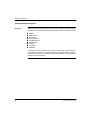
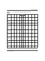
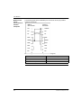
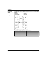
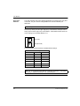
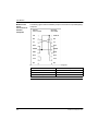
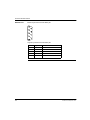
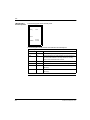
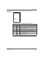
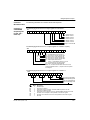
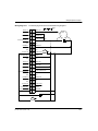
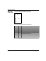
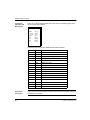
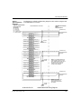
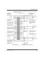
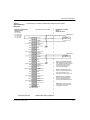
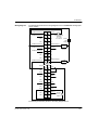
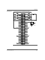
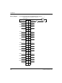
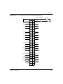
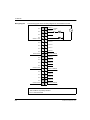
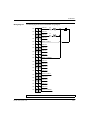
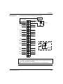
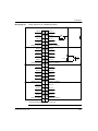
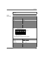
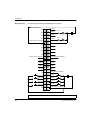
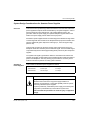
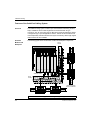
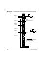
Wiring Diagram
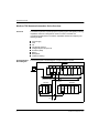
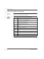
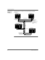
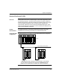
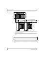
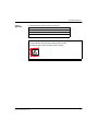
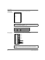
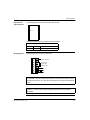
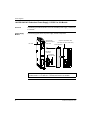
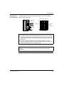
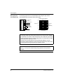
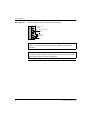
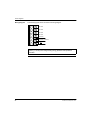
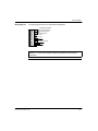
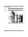
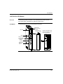
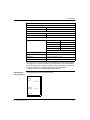
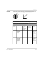
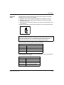
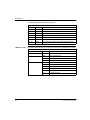
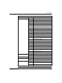
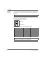
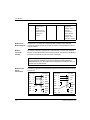
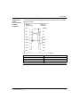
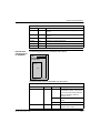
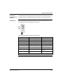
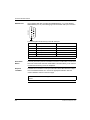
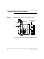
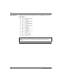
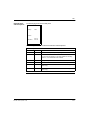
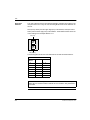
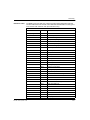
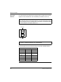
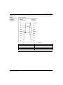
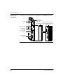
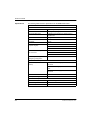
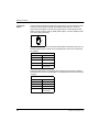
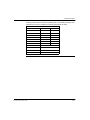
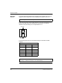
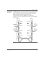
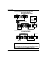
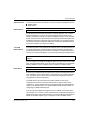
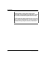
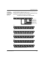
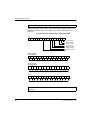
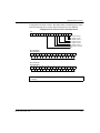
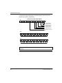
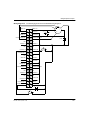
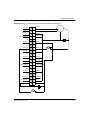
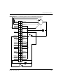
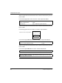
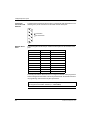
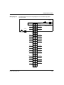
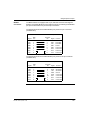
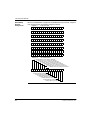
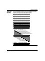
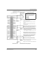
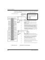
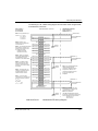
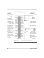
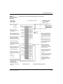
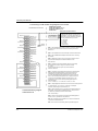
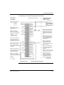
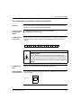
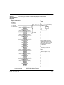
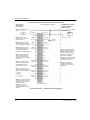
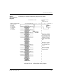
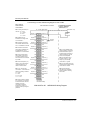
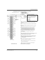
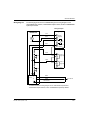
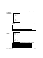
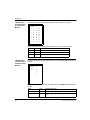
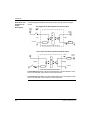
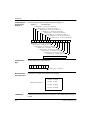
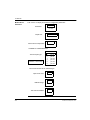
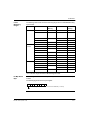
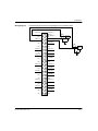
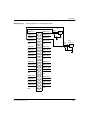
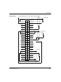
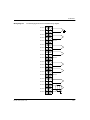
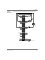
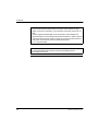
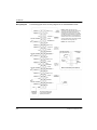
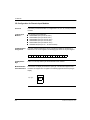
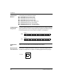
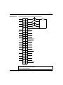
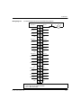
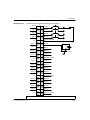
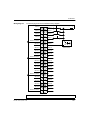
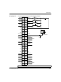
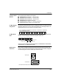
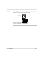
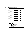
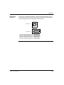
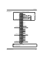
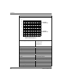
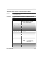
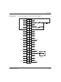
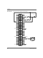
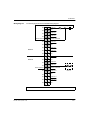
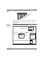
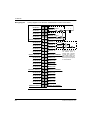
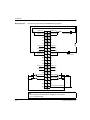
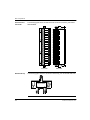
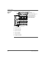
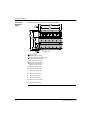
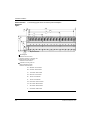
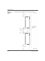
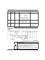
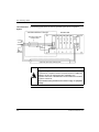
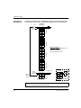
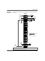
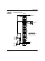
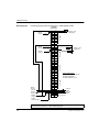
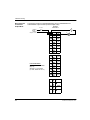
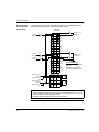
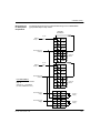
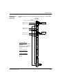
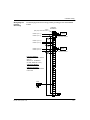
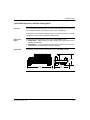
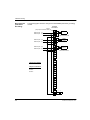
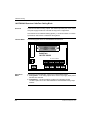
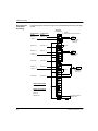
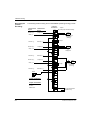
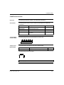
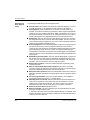
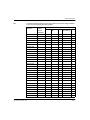
The following figure shows the DRC83000 wiring diagram.
+
2
1
OUTPUT 1 N.O.
4
3
OUTPUT 1 N.C.
N/C
6
5
OUTPUT 2 N.O.
RELAY 2 COMMON
8
7
N/C 10
9
N/C
N/C 12
11
OUTPUT 3 N.O.
RELAY 3 COMMON 14
13
16
15
RELAY 4 COMMON 18
17
N/C
RELAY 1 COMMON
N/C
OUTPUT 3 N.C.
OUTPUT 4 N.O.
OUTPUT 4 N.C.
20
19
N/C
N/C
22
21
OUTPUT 5 N.O.
RELAY 5 COMMON 24
23
26
25
RELAY 6 COMMON 28
27
OUTPUT 5 N.C.
OUTPUT 6 N.O.
30
29
N/C
N/C
32
31
OUTPUT 7 N.O.
RELAY 7 COMMON 34
33
OUTPUT 7 N.C.
36
35
OUTPUT 8 N.O.
RELAY 8 COMMON 38
37
40
39
N/C
OUTPUT
X2 N.O.
N.O.
OUTPUT 6 N.C.
N/C
N/C
See Note 2.
OUTPUT 2 N.C.
N/C
N/C
VOLTAGE
SOURCE
–
OUTPUT 8 N.C.
N.C.
OUTPUT
X2 N.C.
RELAY X
COMMON
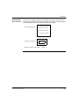
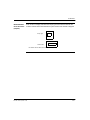
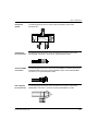
One of Eight Typical
N/C
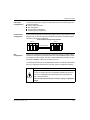
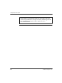
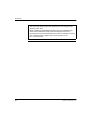
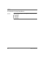
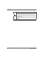
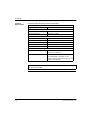
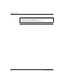
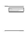
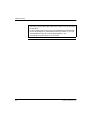
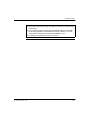
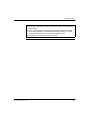
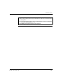
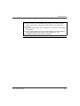
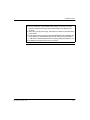
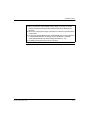
Note:
1. When switching DC voltages, it is recommended that the source be connected
to the common pin and the load be connected to the N.O. or N.C. contact.
2. For 125 Vdc inductive loads, external clamping is recommended to extend relay
contact life (1N 4004 or equivalent).
3. N / C = Not Connected. N.O. = Normally Open. N.C. - Normally Closed.
654
840 USE 100 00 September 2002