1
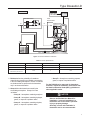
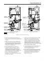
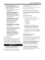
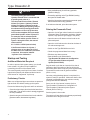
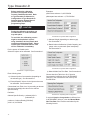
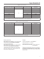
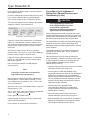
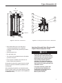
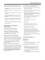
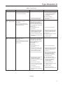
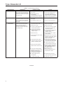
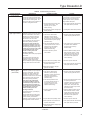
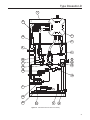
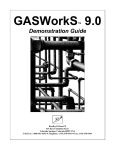
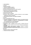
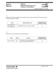
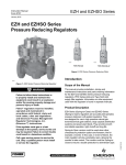
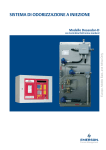
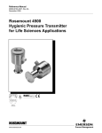
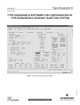
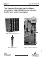
Type Dosaodor-D
Instruction Manual
Form 5790
May 2010
Type Dosaodor-D Odorant Injection System
Controlled by Type ROC809 Remote Telemetry
Unit for North America Installation
Figure 1. Type ROC809 Remote Telemetry Unit
Figure 3. Type Dosaodor-D Pneumatic Panel
D103102X012
Figure 2. Standard Wick Insert
O.M.T.
www.emersonprocess.com/regulators
Type Dosaodor-D
Specifications
Pneumatic Panel:
Solenoid Valves:
Material
Stainless steel plate
Body Material
304 Stainless steel
Installation
Wall mount
Weight
55 to 100 pounds (25 to 45 kg)
(based on configuration)
Gasket Material
Fluorocarbon (FKM)
Valve Operation
Electromagnetic
Overpressure Relief Valve
Maximum Working Pressure
870 psi (60,0 bar)
Power Requirements
12 Vdc
Stainless Steel with Following Rating Options:
200 psi (14,0 bar)
550 psi (38,0 bar)
870 psi (60,0 bar)
Electrical Protection
Explosion proof
Class I, Division 1 and 2 - Groups B, C, D
Class I, Zone 1 and 2 - Groups IIB + H2, IIA
Mechanical Connections
Odorant Inlet and Discharge
1/4-inch (6,4 mm) OD Tube fitting (double ferrule)
Gas Inlet and Discharge
3/8-inch (9,5 mm) OD Tube fitting (single ferrule)
Maximum Working Pressure
Supply: 1450 psi (100 bar)
Injection: 870 psi (60,0 bar)
Odorant Flow Rate
0.13 to 3.70 gallons per hour (0,5 to 14,0 l/hr)
(0.89 to 24.97 pounds/hr at 6.75 pounds/gal)
Temperature Range
14° to 140°F (-10° to 60°C)
Odorant Calibration Cylinder:
Body Material
304 Stainless steel
Maximum Working Pressure
870 psi (60,0 bar)
Maximum Emergency Design Pressure
1450 psi (100 bar)
2
Electrical Protection
Explosion proof
Class I, Division 1 - Groups A, B, C, D
Stabilizer Filter Type SA/2:
Body Material
Steel
Maximum Working Pressure
1450 psi (100 bar)
Gasket Material
Nitrile (NBR)
Type ROC809 Controller
The I/O modules used in the Type ROC809
controller are standard ROC800 Series modules
with no special equipment required
Barrier Specifications
See Table 1
I/O Requirements
See Table 2
Type ROC809 Technical Specifications
Go to: http://www.emersonprocess.com/remote/
Recommended Odorant Filter Specification
50 µm (filter is included)
Type Dosaodor-D
Introduction
Type Dosaodor-D is a computerized odorant injection
system for natural gas using patented solenoid
injector technology that eliminates the need for
plunger pumps.
The solenoid injectors provide odorant injection
accuracy to be maintained over the entire flow range
of the system, approaching infinite turn down.
Automatic calibration during operation adjusts for any
changes in mechanical components and also detects
failures for alarming. Report by exception alarming is
a configurable option.
The system can also be configured to use
redundant injectors and/or an emergency backup or
bypass absorption system.
Real time and historical data can be read locally or
remotely by a laptop computer using ROCLINK 800
configuration software, or remotely using third party
SCADA products utilizing ROC or Modbus protocol.
ROCLINK 800 software is available for complete
configuration and operation of the system including:
• Display of real time and historical data
• Configuration of alarms
• Archival of historical data
Benefits
• Uniform distribution of odorant due to frequent
smaller injections and enhanced absorption
from the wick insertion.
• High turndown ratio. For example, one specific
configuration would evenly distribute odorant at
flow rates from 2000 to 1 200 000 SCFH (53,6 to
32 160 Nm3/h) without mechanical adjustment.
• Automatic calibration of injection system during
normal operation ensuring consistent odorization.
• Environmentally friendly with no venting of gas or
odorant while operating.
• Extremely low maintenance cost.
• Variety of redundancy and backup options for
reliable odorization.
• User friendly configuration software.
• Standard and scalable hardware platform
that supports additional station I/O for AGA flow
calculations and PID control algorithms.
Operation
The Type Dosaodor-D odorant injection system
operates on the basic principle of a fixed differential
pressure and orifice used to measure a noncompressible fluid.
Fixed differential pressure is maintained using double
cut regulation by fixed differential pressure regulators
(Type SA/2 regulators) which reference P2 and reduce
the inlet pressure of a regulating station to P2 + ∆P.
∆Pmin = 8.7 psi (0,60 bar), ∆Pmax = 21.7 psi (1,5 bar)
(an alternate high-pressure source can be used). This
pressure loading of the odorant calibration cylinder
filled with odorant is used to inject liquid odorant into
the downstream pipeline through an on/off valve (the
fixed orifice1) with a known flow coefficient that is
controlled by the automated system. The objective of
the automated control system is to maintain an injection
rate specified by the user which is proportional to the
gas flow. Accuracy of injection is accomplished utilizing
relatively small injections which are automatically
resized over a wide range dependent upon variations
in the gas flow. This results in a turn down ratio for
the system that can exceed 500:1 (the addition of a
simple bypass system utilizing the odorant storage
tank can allow the turn down ratio to approach infinity).
An odorant calibration cylinder with a fixed volume is
utilized to recalibrate the injection valve flow coefficient
each time the odorant calibration cylinder is refilled.
During the refill cycle the pressure used for injection is
relieved into the downstream pipeline which eliminates
venting of gas to atmosphere or an expansion tank.
Liquid odorant refill of the odorant calibration cylinder
is typically accomplished by using all or some part of
the P2 + ∆P pressure to load the odorant storage tank
thus pushing the liquid out of the tank and into the
odorant calibration cylinder, ∆P=8.7 to 21.7 psi
(0,60 to 1,5 bar).
Since the unit uses only pressure for injection there
are few moving parts in the system resulting in very
little maintenance. Relatively low cost options for both
automated and emergency redundancy for odorization
are also available.
The gas flow rate is obtained through either a
corrected gas volume pulse input or an instantaneous
flow rate analog input (4 to 20mA) signal. The gas
1. Although the valve orifice is fixed for a specific application the valve can be adjusted manually to accommodate flow rates as small as 2 MSCFH to over 33 000 MSCFH with one injector.
3
Type Dosaodor-D
flow rate can also be configured manually to a fixed
value. Odorant injection rate is then calculated using
accumulated flow in order to reduce variability.
In cases where the station does not have a flow
computer, the Type ROC809 can be connected
directly to a pulse output from the turbine, or an
analog output from a differential pressure transmitter
(Rosemount Types 3051 and 3095, etc.).
Variability between the calculated and actual injection
volume is used to automatically adjust injection
parameters for any changes in the system and
to detect alarm conditions or system failure, the
odorant calibration cylinder is used to monitor the
actual use of odorant. In the event of power failure,
configuration information and archived historical data
are maintained.
Type Dosaodor-D is designed to purge the odorant
back into the tank in the event that mechanical
maintenance is required. Odorant is pushed back
into the tank and gas is purged through the system to
absorb any remaining liquid.
General Safety Rules
Only qualified personnel shall install and operate the
odorizing system.
Odorizing systems should be installed, operated,
and maintained in accordance with international and
applicable codes and regulations.
Installation, operation, and maintenance procedures
performed by unqualified personnel may result in
unsafe operation.
This condition may result in equipment damage or
personal, environment injury. If a leak develops in
the system, the escaping gas may accumulate and
become a fire or explosion hazard. Immediately call
qualified service personnel in case of trouble.
Site Requirements
Careful consideration when locating the ROC809 on
the site can help reduce future operational problems.
Consider the following items when choosing a location:
• Local, state, and federal codes often place restrictions on locations and dictate site
requirements. Examples of these restrictions are:
the amount of distance from a meter run, distance
from pipe flanges, and hazardous area classifications. Ensure that all code requirements are met.
• Choose a location for the ROC that minimizes the length of signal and power wiring.
• The ROC809 is equipped for radio communications should be located so the antenna has an unobstructed signal path. Antennas should not be aimed into storage tanks, buildings, or other
tall structures. If possible, antennas should be located at the highest point on the site. Overhead
clearance should be sufficient to allow the antenna to
be raised to a height of at least 20 feet (6 m).
• To minimize interference with radio communications, choose a location for the ROC away from
electrical noise sources, such as engines, large
electric motors, and utility line transformers.
• Choose a location for the ROC away from heavy
traffic areas to reduce the risk of being damaged
by vehicles. However, provide adequate vehicle
access to aid monitoring and maintenance.
• The site must comply with class limits of Part 15
of the FCC rules. Operation is subject to the
following two conditions: (1) The device may not
cause harmful interference, and (2) the device must
accept any interference received, including
interference that may cause undesired operation.
Compliance with Hazardous Area Standards
The service engineers (operators and maintenance
workers of odorizing systems) shall comply, in any
case, with the following rules:
The ROC hazardous location approval is for Class I,
Division 2, Groups A, B, C, and D. The Class, Division,
and Group terms include:
1. Always wear safety clothing to prevent the product
from coming in contact with the skin, eyes, or to
prevent it from being inhaled;
1. Class defines the general nature of the hazardous material in the surrounding atmosphere. Class I is for locations where flammable gases or vapors may be present in the air in quantities sufficient to produce explosive or ignitable mixtures.
2. In case of leaks or liquid spillage, be prepared to
neutralize or contain the liquid.
4
Type Dosaodor-D
SAFE AREA
HAZARDOUS AREA
SIGNALS FROM
FLOW COMPUTER
REGULATING STATION
TYPE ROC809
LIQUID
INJECTION POINT
P1
PNEUMATIC PANEL
P2
ODORANT
TANK
KEY 40 - ODORANT FILTER
Figure 4. General Installation Schematic
Table 1. Barrier Specifications
I. S. BARRIER PARAMETERS
MUST BE
LEVEL SWITCH + CABLE PARAMETERS
1
Co
≥
Ci + Cc
2
Lo
≥
Li + Lc
Lo/Ro
≥
Lc/Rc
3
Alternative to previous one
2. Division defines the probability of hazardous material being present in an ignitable concentration in the surrounding atmosphere. Division 2 locations are locations that are presumed to be hazardous only in an abnormal situation.
3. Group defines the hazardous material in the surrounding atmosphere. Groups A to D are
as follows:
• Group A – Atmosphere containing acetylene.
• Group B – Atmosphere containing hydrogen,
gases, or vapors of equivalent nature.
• Group C – Atmosphere containing ethylene, gases, or vapors of equivalent nature.
• Group D – Atmosphere containing propane, gases, or vapors of equivalent nature.
For the ROC809 to be approved for hazardous
locations, it must be installed in accordance with
the National Electrical Code (NEC) guidelines or
other applicable codes.
NOTICE
Refer to the ROC809 User Manual for
installation. Incorrect installation in a
hazardous area could result in personal
injury or property damage.
Generally, control unit installation in
hazardous area is not recommended.
5
Type Dosaodor-D
SAFE AREA
HAZARDOUS AREA
SIGNALS FROM
FLOW COMPUTER
TYPE ROC809
REGULATING STATION
P1
P2H
SOLENOID VALVE
P2L
P2
PNEUMATIC PANEL l
SOLENOID VALVE
ODORANT
TANK
KEY 40 - ODORANT FILTER
*SUPPLIED BY SYSTEM INTEGRATOR
Figure 5. Automated Pressure Balancing System with Bypass Schematic
CAUTION
When working on units located in a
hazardous area (where explosive gases
may be present), make sure the area is in
a non-hazardous state before performing
procedures. Performing procedures in a
hazardous area could result in personal
injury or property damage.
Best Practices for Installation
1. Install a sight/drip glass to monitor odorant
injection. If the odorant storage tank is large,
a bypass is recommended to reduce the time it
takes to pressurize the tank.
2. Before installing the pneumatic panel, verify float
activation of magnetic switches in odorant
calibration cylinder. Use an Ohm meter and
6
validate that when the panel is upright and the
float is at the bottom one set of wires has
conductivity (brown). Then tip the panel upside
down which will cause the float to slide up the
stem to the high level magnetic switch and the
second magnetic switch wire should then have
conductivity (green).
3. Get and read the Type Dosaodor-D Software for Configuration of Type Dosaodor-D Odorant Injection
System Manual (D103117X012). Get the information that is printed on the panel for odorant
calibration cylinder capacity (CONTROL DEVICE
VOLUME) and injector valve flow coefficients (SPECIFIC VOLUME INJECTOR N° X). Get the
three values related to the used odorant: specific
gravity (normally about 0.6); specific weight
(normally about 6.75 pounds per gallon) and finally
the initial injection rate (normally in the 0.5 to
1.0 pound of odorant per million cubic feet of
gas range).
Type Dosaodor-D
2
1
2
1
ODORANT LINE
TO PIPELINE,
1/4-INCH OD TUBE
ODORANT LINE
TO PIPELINE,
1/4-INCH OD TUBE
2
1
2
1
3
3
M
P2 (STATION OUTLET)
PRESSURE LINE,
3/8-INCH OD TUBE
ODORANT LINE
FROM TANK,
1/4-INCH OD TUBE
M
V
V
P2 (STATION OUTLET)
PRESSURE LINE,
3/8-INCH OD TUBE
R
V
P1 (STATION INLET)
PRESSURE LINE
3/8-INCH OD TUBE
R
P1 (STATION INLET)
PRESSURE LINE,
3/8-INCH OD TUBE
M
1
ODORANT LINE
FROM TANK
1/4-INCH OD TUBE
2
PNEUMATIC PANEL B1 VERSION
1
2
3
1
2
R
V
R
M
1
2
PNEUMATIC PANEL B2 VERSION
PRINTED ON SOLENOID VALVE
Figure 6. Connections for Pneumatic Panel
4. Install quarter turn hand valves at each end of
tubing runs for easy isolation during troubleshooting
or repairs.
5. Install “Pete’s Plugs” so that a pressure gauge
can be placed into different parts of the system
(e.g. storage tank pressure, pressure at point of
pipeline injection; pipeline, or supply pressure to
Type SA/2) for troubleshooting.
6. If odorant storage tank is kept at P2 + ∆P
pressure then a flow control valve must be
installed in the liquid line to control refill time.
Swagelok flow control (metering) valves are
recommended: M and 31 Series. Suggested refill
time: 45 seconds minimum to 120 seconds.
However, if the storage tank floats with
the pipeline by using added solenoid valves, then
this valve is not needed.
7. As above, refill of the odorant calibration cylinder
should take at least 45 seconds to a couple
minutes. Considering this value, assume that
odorant is already at the low level of the odorant
calibration cylinder (you have not purged the
odorant back into the tank or are not just starting
up the system and need to fill all the tubing coming
to the odorant calibration cylinder).
8. Type ROC809 digital output modules (DOs) do not
drive the solenoids directly; wires are used to
power the supply (see Figure 8).
9. Get a cross over ethernet cable to connect directly from a PC to the Type ROC809 ethernet port. See
Type Dosaodor-D Software for Configuration of Type Dosaodor-D Odorant Injection System
Manual (D103117X012).
7
Type Dosaodor-D
Table 2. I/O Requirements(1)
REQUIREMENT
DESCRIPTION
1
Optional
Communication Card
Not Applicable
6.3:COM
2
Optional
Communication Card
Not Applicable
6.3:COM
3
Optional
Communication Card
Not Applicable
6.3:COM
4
Choose according
to Flow Rate input
5
Choose according
to Flow Rate input
Pulse Inputs
POINT DESCRIPTION
(SPECIFICATION
SHEET)
SLOT
Channel 1: Flow Input from computer or pulse meter
Channel 2: Spare
6.3:PI
Channel 1: Flow Input from computer
Analog Inputs
Channel 2: Supply tank level input
Channel 3: Spare
6.3:AI
Channel 4: Spare
Channel 1: Odorant calibration cylinder high level
Channel 2: Odorant calibration cylinder low level
Channel 3: Gas flow computer alarm(2)
6
Required
Discrete Inputs
Channel 4: Spare
Channel 5: Spare
6.3:DI
Channel 6: Spare
Channel 7: Spare
Channel 8: Spare
Channel 1: Instantaneous Odorant Concentration
7
Optional
Analog Outputs
Channel 2: Average Odorant Concentration for Current Day
Channel 3: Spare
6.3:AO
Channel 4: Spare
Channel 1: Injector #1 solenoid
Channel 2: Injector #2 solenoid
8
Required
Discrete Relay Outputs
Channel 3:Odorant calibration cylinder pressure solenoid/Tank
pressure solenoid
6.3:IOM3
Channel 4: Odorant calibration cylinder refill control solenoid
Channel 5: System is offline
Channel 1: Alarm Output
Channel 2: Low odorant supply tank level
9
Required
Discrete Relay Outputs
Channel 3: Gas volume output pulse
6.3:IOM3
Channel 4: Odorant volume output pulse
Channel 5: Spare
1. Each module must be inserted in the assigned slot.
2. This point should be manually reconfigured if it is not connected to an external flow computer see Dosaodor User Manual (D103117X012), Alarm Output
Contact Selection, Flow Computer.
10. For the low flow conditions, set the odorizer
control program scan time to 20 seconds (default
is 2 seconds) to improve current value read out
for flow. See Type Dosaodor-D Software for Configuration of Type Dosaodor-D Odorant Injection System Manual (D103117X012).
11. Review configuration of system, set alarm,
and other parameters while mechanical
installation is in progress (including odorant
calibration cylinder volume and initial injector
valve flow coefficient(s)). See Type Dosaodor-D Software for Configuration of Type Dosaodor-D
Odorant Injection System Manual (D103117X012).
8
12. Spend time training on the operation,
configuration, and troubleshooting tools for
the system.
13. After landing all control wiring and before loading
the system with pressure, activate each digital
output to verify correct wiring and operation
of solenoids.
14. In an orderly manner pressurize the system with
nitrogen (IF USED) from the high pressure supply
and for reference to the pipeline pressure.
15. Check tubing and fittings for any leakage.
Type Dosaodor-D
16. Open liquid odorant fill tubing valve to odorant
calibration cylinder and check for leaks.
17. Do a manual refill of the odorant calibration
cylinder; check for any leaks in tubing and fittings
and correct operation of magnetic switches.
18. Do a purge of the odorant calibration
cylinder (for training and correct operation
of components).
19. Refill odorant calibration cylinder.
20. Set operation mode to Manual and set flow rate
to high level (50 000 MCFH to 75 000 MCFH) in
order to push odorant through the injection
solenoids and remaining tubing down to
the pipeline.
21. Once odorant appears in sight glass, place
system in Automatic mode and continue setting
up configuration parameters.
22. Observe first refill of odorant calibration cylinder
and recalculation of injector flow coefficient.
23. After a period of operation and allowing several
odorant calibration cylinder refills, analyze actual
injection rate against target. To confirm everything
is working correctly locate a calibration refill (at the
top of the hour) in the event log. Next, find where
there was another refill at the top of another hour,
this may be several hours or even days later.
Count the number of refills that occurred during that
time. The volume of the odorant calibration cylinder
tells you how much odorant was measured into the
pipeline during that time. Referring to the
computer, you can add up the gas flow during that
same period since AGA calculations are
summarized for each hour at the top of the hour.
Now you can divide the volume of odorant you
calculated by the gas flow volume for the same
period and verify the injection rate.
Injection System Configuration Schemes
The Type DOSAODOR-D product works using the
differential pressure that is present in regulating
station. For non-differential applications (no regulating
stations involved) please refer to appropriate solutions
and related documentation.
Installation schematic depends on the application and
needs of the customer. In the following pages, good
practices and best practices will be described.
Just to give an idea about different configurations and
installation options (see Figures 4 and 5), the following
are the most common:
1. Additional odorant flow control valve may be
used on odorant liquid line when odorant storage
tank is maintained at P2 + ∆P. ∆P = 8.7 to 21.7 psi
(0,60 to 1,5 bar). CV for built-in control valve
(position 23, Figures 12, 13): CV = 0.11. Odorant
calibration cylinder refill time should be contained
in the 45 to 120 seconds. If these constraints
cannot be satisfied tuning the built-in flow control
valve, an additional flow control valve must be
used according to working conditions, to obtain
the required refill time. Swagelok flow control
(metering) valves are recommended: M and
31 Series.
2. Optional 3-way valve for pressurizing odorant
storage tank to P2 + ∆P. ∆P = 8.7 to 21.7 psi
(0,60 to 1,5 bar) when tank is maintained at P2.
When the 3-way valve is not energized then the
storage tank is maintained at (floats with) P2.
When it is energized for a liquid refill of the odorant
calibration cylinder then the pressure begins going
up towards P2 + ∆P bar until the refill is completed.
3. Optional 3-way valve for maintaining odorant
storage tank at P2. This is commonly used with
option 2. Refer to Figure 5.
4. Option for odorant storage tank relief to P2. If P2
pressure (refer to Figures 4 and 5) is highly
variable or there is excess buildup of pressure in
the storage tank due to temperature changes
and at the same option 2 is not used, then a
simple pressure relief valve may be needed to
relieve excess pressure from the storage tank into
P2 stream.
5. Option for odorant calibration cylinder relief to P2. If
the pressures in P2 are highly variable, like what
may occur in a straight line pipe with no regulator
station, then the pressure in the odorant calibration
cylinder may be raised to a value that is too high
for the system to work properly during operations. To
resolve this issue a relief valve may be installed
across the 3-way valve on the pneumatic panel,
to vent excess pressure from the odorant calibration
cylinder into the downstream pipeline.
6. Options for utilizing odorant storage tank as a
bypass or absorption system. This functionality
may be activated by the Type Dosaodor-D system
when disabled or in fault.
9
Type Dosaodor-D
Most frequent combinations.
A. 1 and 6 with 4 and/or 5
B. 2 and 3 with 6
C. 4 and/or 5 with 6
D. 2 and 3 should be used together
Type ROC809 Controller Installation
Planning is essential to a good installation. Because
installation requirements depend on many factors,
such as the application, location, ground conditions,
climate, and accessibility, this document only provides
generalized guidelines.
Pneumatic Panel Installation
Pneumatic Panel should be installed in the immediate
vicinity of the odorant pick-up point (absorption-type tank
or other type of tank).
All of the panel components are resistant to chemical
attack from all of the odorizing liquids, to the elements
and to those conditions specified in regulations
regarding safety and electrical equipment.
It is essential that the distance between the panel and
the injection location be as short as possible, as a
short route limits the quantity of odorant subjected to
pressure and thus reduces the chances of leakage of
liquid occurring.
The pneumatic panel (Figure 3) is intended to be
wall mounted. Two spacing brackets are part of the
standard equipment supplied with the panel. The
standard equipment contains two brackets, standard or
extended injection wick, odorant filter, and screws.
Four openings are provided for pipe connections, and
they are located at the end points of the support panel.
The positions and sizes of the openings can be easily
identified from Figure 6.
Pneumatic Lines and Connections
The pneumatic connections between the
Type Dosaodor-D panel, the gas line, and the
odorant tank should be carried out using stainless
steel piping only. Refer to Figure 6 for pipe sizes.
CAUTION
The pipeline connecting the
Type Dosaodor-D panel with the
odorant tank should be configured to
avoid the creation of possible air/gas
pockets (obstacles to the odorant flow).
Piping should be installed as straight as possible,
with a constant grade, and without any sequences of
upward and downward inclines.
Polytetrafluoroethylene (PTFE) tape or thread sealer
should be used on all pipe fittings to prevent
odorant leakage.
10
!
WARNING
Failure to follow the following installation
requirements could result in equipment
malfunction and loss of odorant
injection. Loss of odorant in the natural
gas supply could result in personal
injury and property damage from
undetected leaking natural gas.
Level Float and Switch Wiring
Type ROC809 must not receive the signals directly
from the odorant calibration cylinder (low and high
level). For safety reasons a barrier must be installed.
Barrier Specifications
Verify connection cable and field device capacitance
and inductance do not exceed the limits given for the
Intrinsically Safe barrier.
Level Switch Safe Parameters:
Ci (Equivalent input capacitance) = 20pF
Li (Equivalent input inductance) = 4μH
If the results are negative, condition 3 prevails on 2, since
cable resistance reduces circuit current (consequently
reducing the stored electrokinetic energy).
Cable parameters:
Cc (Equivalent input capacitance)
Lc (Equivalent input inductance)
Rc (Equivalent input resistance)
Environmental Requirements
NOTICE
The ROC809 requires protection
from direct exposure to rain, snow,
ice, blowing dust or debris, and
corrosive atmospheres.
Type Dosaodor-D
In salt spray environments, it is
especially important to ensure that the
enclosure is sealed properly, including
all entry and exit points.
• Always install the ROC809 in a user supplied enclosure.
• If the ROC809 is installed outside a
building, it must be placed in a
National Electrical Manufacturer’s
Association (NEMA) 3 or higher rated
enclosure to ensure the necessary level of protection.
• The ROC809 operates over a wide
range of temperatures. In extreme
climates it may be necessary to
provide temperature-controlling
devices to maintain stable
operating conditions.
• In extremely hot climates, a filtered
ventilation system or air conditioning
may be required.
• In extremely cold climates, it may be
necessary to provide a thermostatically
controlled heater in the same
enclosure as the ROC809.
• To maintain a non-condensing
atmosphere inside the ROC809
enclosure in areas of high humidity,
it may be necessary to add heat
or dehumidification.
I/O Configuration
Several options are available on the Type ROC809
controller. Outputs may be added to interface
with external devices such as systems for remote
data transmission, remote monitoring, and remote
surveillance. Table 2 lists the minimal requirements.
NOTICE
Each module must be inserted in the
assigned slot as shown in Table 2.
Further configuration information is provided in
the Type Dosaodor-D Software for Configuration
of Type Dosaodor-D Odorant Injection System
Manual (D103117X012).
Refer to the ROC809 Remote Operations Controller
Instruction Manual (Form A6116).
Electrical Connections Schematics
The electrical connections between the enclosure and
pneumatic panel should be completed according to
Figures 7 and 8.
Preliminary Checks
Before turning on the electronic control unit:
1. Gas Volume/Gas Delivery signal type must be set
to one of the following input signals:
• Pulse input
• Analog input
• Internal Orifice
• Internal Turbine
2.
Check all of the electrical and pneumatic
connections for proper conformity throughout
the entire system, using the diagrams and
drawings supplied by the system integrator.
3. Make sure that all of the valves for connection
between the pneumatic panel and remaining part of
the station are leak free. Turn on the electronic
control unit.
Control Unit Power-On and
Parameters Set-Up
After all of the checks in the preceding section and
suggested by the system integrator have been carried
out, turn on the system, set it in Disable mode and
configure parameters as described in:
“Procedure and Compilation of Work Parameters”
chapter of Type Dosaodor-D Software for
Configuration of Type Dosaodor-D Odorant
Injection System Manual (D103117X012).
Programmed and Displayed Data
Please refer to Type Dosaodor-D Software for
Configuration of Type Dosaodor-D Odorant Injection
System Manual (D103117X012).
11
Type Dosaodor-D
Remote operations
controller enclosure
Safe area
Remote operations
controller enclosure
Safe area
I.S.
Barrier
I.S.
Barrier
ROC809
ROC809
Pneumatic Panel
Pneumatic Panel
Junction
box 2
-
Injector 2
solenoid valve
+
B -->6
-
Injector 1
solenoid valve
+
B -->4
Odorant
calibration cylinder
solenoid valve
A -->5
White
B -->6
Junction
box 1
-
White
-
Injector 1
solenoid valve
Odorant calibration
cylinder pressure
solenoid valve
+
A -->3
B -->4
-
+
A -->1
+
Odorant calibration
cylinder control
solenoid valve
A -->1
Odorant calibration
cylinder refill
solenoid valve
B -->2
-
B -->2
-
Hazardous area
Hazardous area
TYPE DOSAODOR-D B1 VERSION
TYPE DOSAODOR-D B2 VERSION
Figure 7. Electrical Connections Schematics
12
Green
High
+
Green
High
Brown
Low
A -->3
8765432 1
B -->8
65432 1
A -->5
Junction
box 2
+
A -->7
Brown
Low
Junction
box 1
Type Dosaodor-D
+12 V
Com.
DI
CPU
ETHERNET
CPU
ETHERNET
R OC809
R OC809
LO I
RS-232D
LE D
+12 V
Com.
#2
RESET
BROWN - LOW
4
5
#1
7
#2
8
RESET
RX
RX
GREEN - HIGH
2
6
LICENSE
KEY S
RX
RX
RS-232
DTR RT S TX
RS-232
DTR RT S TX
ETHERNET
LN K CO L TX
ETHERNET
LN K CO L TX
CABLE
Ethernet cable ETHERNET
Ethernet
cable
C OM
LICENSE
KEY S
#1
1
3
ST AT US
ST AT US
LO I
LE D
+12 V V
+12
COM.
Com.
RS-232D
ble
GND
8 CHAN
GND
REFER TO TYPE DOSAODOR-D SCHEMATICS
ON PAGE 12 JUNCTION BOX 1
ETHERNET CONNECTION
-
2
3
7
+ 7
InjectorINJECTOR
2
2
12 Vdc
- 12
V SUPPLY
solenoidSOLENOID
valve VALVE
+
-
44 -
+
+
+
-
42 -
DI
Green - Low
2
Brown - High
5 CHAN
1
88 -
1
4
4
5
5
PRESSURE
SOLENOID
1
6 + 3
CylinderODORANT
refil
DO
DO
12 Vdc
VY SUPPLY
- 12
CALIBRATION
RELA
control solenoid
RELAY
Green - Low
+
Brown - High
CH 2
3
ODORANT
3
+ 3
CALIBRATION
Cylinder/tank
CYLINDER/TANK
12 Vdc
V SUPPLY
- 12
pressure solenoid
CYLINDER REFILL
CONTROL
+
8 SOLENOID
CH 1
+
5
+ 5
1
InjectorINJECTOR
1
12 Vdc
V SUPPLY
- 12
solenoidSOLENOID
valve VALVE
-
+
CH 2
CH 5
DI
CH 4
CH 3
CH 2
CH 1
w
gh
66 -
CH 1
DO
RELAY
SUPPLY VOLTAGE CONNECTIONS
-
+
-
CH 3
+
SOLENOID VALVES CONNECTIONS
8 CHAN
-
+
-
CH 4
-
CH 5
C OM
8 CHAN
CH 4
8
C OM
7
8
CH 5
7
CH 3
REFER TO TYPE DOSAODOR-D SCHEMATICS ON PAGE
12 JUNCTION BOX +2.
+
6 POWER SUPPLY IS NEEDED.
EXTERNAL
6
ODORANT
CALIBRATION
CYLINDER HIGH
CONTACT
(GREEN WIRE)
DISCRETE INPUT CARD
7
Com
2
8
1
INPUT 1 - HIGH LEVEL
3
9
2
INPUT 2 - LOW LEVEL
4
1 OFF
10
5
2 OFF
11
6 3 ON
12
ODORANT
CALIBRATION
13
5
LOW
6 + CYLINDER
+ 5
+T
14
CONTACT Injector 1
Injector
1
12 V WIRE)
- (BROWN
12 V solenoid
solenoid- valve
Com
15
valve
PULSE INPUT CARD*
USE TO PROVIDE
POWER FOR THE
BARRIER JUMPER SET
FOR 24 VDC
8 7
+ 7
Injector +2
Injector 2
- 12 V solenoid- valve
12 V solenoid valve
*ALTERNATIVE POWER FOR THE BARRIER:
ANALOG INPUT BOARD (AI - 12).
4 -
4 3
+ 3
Cylinder+ refil
Cylinder refil
- 12 V control solenoid
- 12 V control solenoid
-
SAFE AREA
1
4 + 3
+ 3
Cylinder/tank
Cylinder/tank
- 12 V pressure- solenoid
12 V pressure solenoid
+
+
I.S. BARRIER SAMPLE
CHECK PARAMETERS ACCORDING TO I.S.
BARRIER PARAMETER TABLE
KFD2 - SR2 - EX2. W (PEPPERL AND FUCHS)
4 -
-
HAZARDOUS
AREA
LEVEL SWITCH CONNECTIONS
BARRIER
Figure 8. Type ROC809 Electrical Connections
5 CHAN
5 CHAN
13
Type Dosaodor-D
NOTICE
The factory tuning procedure of the
injection solenoid valve is conducted with
a specific gravity value of 1.
The value entered in the fields “Entered
Volume For Injector 1 (lbs/sec), Entered
Volume For Injector 2 (lbs/sec) must be
calculated. Multiply the specific gravity of
the odorant to be injected (typical values
range between 0.5 and 1.0) by the value
found on the nameplate of the pneumatic
panel titled: Specific volume injector N°1.
For example, with an odorant specific
gravity of 0.6 and the specific volume of
injector 1 being 0.0132 lb/s, the entered
value would be:
0.6 * 0.0132 = 0.00792 (entered value)
If the Entered Volume for Injector 1
changes more or less than the 10% of
the label value, the calibration procedure
is required. See section labelled
“Injection Valve Calibration.”
Startup and Testing
Additional Materials Required
In order to proceed with system startup, you should
have at least 0.14 gallon of liquid capable of
neutralizing the effect of the odorant used.
The most frequently used liquid is a mixture of sodium
hypochlorite (bleach) with denatured alcohol and a
small amount of “fragranced” liquid soap.
Preliminary Checks
Make sure all pipe and pipe connections are pressure
tight and leak free before starting up the system.
Proceed as follows using Figures 4 and 5 as reference:
• Close the odorant input valve found at the base of the pickup tank. The use of this valve is strongly suggested
for every installation.
• Open the two gas on/off valves found on the main line (upstream station, downstream regulators).
14
• Using a suitable spray, check for any gas leaks (check ALL fittings).
• Proceed by switching on the Type ROC809, setting the system in Disable mode.
• Check the line section connecting the pneumatic panel with the odorant tank for any gas leaks.
If no leaks are detected, prime the entire system.
Priming the Pneumatic Panel
• Open the 4 on/off gas valves found on the main line (Upstream filters, Downstream regulators, Odorant injection, High-pressure gas supply to the panel).
• Open the two on/off odorant valves found on the pneumatic panel.
• Open the on/off odorant valve found at the base of the odorant storage tank.
• Switch on the Type ROC809 control unit.
• Check the programmed data for accuracy.
• Eliminate any alarms present.
• Start the Wash cycle as described in
Type Dosaodor-D Software for Configuration of Type Dosaodor-D Odorant Injection
System (D103117X012).
Stop the wash cycle after an interval of time that is
sufficient to drain the section of the line joining the
pneumatic panel with the injection point: Approximately
12 seconds for each meter of pipeline installed
(DN 6 x 4 mm).
Once the priming/drainage phase is completed, the
system is ready for operation. Make sure that the flow
computer is transmitting the gas volumes correctly
(Using ROCLINK 800 Software).
Set to zero all of the internal counters (look at
Type Dosaodor-D Software for Configuration of
Type Dosaodor-D Odorant Injection System
manual (D103117X012)).
Set the system in Auto mode.
The system will start dosing the odorant proportionally
to the flow rate of the gas in transit.
Type Dosaodor-D
Maintenance and Operation
Injection Valve Tuning
Procedures and Recommended
Timing for Routine/Extraordinary
Maintenance Operations
The Type Dosaodor-D system that you have
purchased has been manufactured with state-of-theart technology and materials currently available.
Type Dosaodor-D odorizing system and its
accessories are subjected to normal wear/aging and
must be inspected periodically.
The frequency of inspection/checks and replacement
depends upon the severity of service conditions and
upon applicable National or Industry codes, standards,
and regulations/recommendations.
Maintenance may be accomplished following proper
procedures that are detailed in the Instruction Manual.
Routine Maintenance:
• Cut-off power supply to the electronic control unit.
• Depressurized the pneumatic panel by loosening
the joint located in the upper left part of the
control odorant calibration cylinder.
Recommended Parts Replacement
• Replace all rubber parts inside the two pressure
filter-regulators model Type SA/2.
• Replace the filter cartridge located inside the
filter housing.
Restart the system, following the instructions
described in “Startup and Testing” section.
Extraordinary Maintenance:
It shall be carried out in case the system stops
injecting the necessary odorant quantity. Alarm
messages may highlight this condition. Please refer to
troubleshooting section.
Professionally trained staff is required to perform
maintenance operations.
For routine maintenance operations, refer to the parts
list and appropriate assembly drawings. It includes all
spare parts that may need to be replaced in the system
enabling the system to comply with the functional
specification it was originally designed.
Operators shall perform mechanical/pneumatic
interventions, and be well informed on all instructions
related to safety operations, that have to be met during
any intervention on systems managing flammable and/or
odorizing liquids.
System Shutdown
Injection Valve Calibration
!
WARNING
To avoid personal injury or property
damage from sudden release of
pressure, isolate the equipment from
the pressure system, and release all
pressure from the connections before
performing maintenance operations.
These are the operations to be carried out:
• Purge/Wash cycle by means of Natural Gas
(follow the procedure on page 18).
• After completing the Purge/Wash Cycle, close all
valves on the pneumatic panel.
• Close the needle valve located on the pipe detecting the odorizing pressure (low pressure branch).
• Close the odorant outlet valve located on the tank
from which the odorant is picked up.
NOTICE
In some cases, the Injection valve
may need calibration. This may be
needed when:
1. Injector alarms take place frequently.
2. The injection solenoid valve is
replaced with a new one that has not
been calibrated.
3. During startup, if the injection
solenoid valve calibration is not
adequate to the working conditions
(frequent injector alarms may
take place).
4. The Entered Volume for the injector
changes more or less than 10% of
the label value.
15
Type Dosaodor-D
Before starting the calibration
procedure, the system must be
correctly installed and tested. Refer
to Type Dosaodor-D Software for
Configuration of Type Dosaodor-D
Odorant Injection System Manual
(D103117X012) for following
programming steps.
Examples:
ρSulfur base odorant = 8,345 LBS/Gal
ρMercaptan base odorant = 6,776 LBS/Gal
CAUTION
During the calibration procedure gas
overodorization or underodorization
may take place.
To avoid this, the calibration process
might be accomplished “off-line”
using simulation devices (Plastic tank
containing anti-freezing liquid). Please
contact your local Sales Office in case
off-line calibration is mandatory.
Put the system in Disable mode.
Select the injector to be calibrated. See Screenshot 1.
Screenshot 2: Injection Data Configuration
c) Odorant Weight (depending on odorant type).
See Screenshot 3.
d) Rated Odorant Calibration Cylinder Capacity (see
proper value on pneumatic panel nameplate).
See Screenshot 3.
Screenshot 3: Injection Data Configuration
Screenshot 1: Injection System
Enter following data:
a) Odorant Injection Concentration (depending on
the odorant type). See Screenshot 2.
b) Entered Specific Volume for the Injector that must
be calibrated. See Screenshot 2.
e) Manual Mode Gas Flow Rate. See Screenshot 4.
Choose data from Table 3a or 3b; if Injection
Concentration is different from 2,48 LBS/MMCF
(40mg/m3), then calculate the new value by the
formula below.
Choose data from Table 3a or 3b (according to odorant
flow rate) and multiply this value for the odorant
Specific Gravity.
Definition:
Odorant Specific Gravity = ρodorant/ρH2O = ρodorant/8,32
ρodorant = Odorant Density [LBS/Gal]
ρH2O = 8,32 LBS/Gal
16
Screenshot 4: Operating Data Configuration
If required Injection Concentration is different from
2,48 LBS/MMCF (40mg/m3) then the Manual Mode
Gas Flow Rate value must be recalculated by the
following formula:
Type Dosaodor-D
Table 3a. Imperial Parameters
ODORANT FLOW RATE
(SEE PNEUMATIC PANEL NAMEPLATE)
INJECTION CONCENTRATION
MANUAL MODE GAS FLOW RATE
SPECIFIC VOLUME
FOR INJECTOR(1)
MCF/h
LBS/MMCF
MCF/D
LBS/sec
17,7
9.531
0,00165
35,3
19.062
0,00330
70,6
38.124
0,00660
141,3
76.248
0,01320
114.372
0,01980
282,5
152.496
0,02640
353,1
190.620
0,03300
423,8
228.744
0,03960
494,4
266.868
0,04620
211,9
2,48
1. The specific volume entered for injector must be calculated. Multiply the specific gravity of the odorant to be injected (typical values range between 0.5 and 1.0) by the value that may
be found on the nameplate of the pneumatic panel titled: Specific volume injector N°1. These values are listed in right column of above table. Example, with an odorant specific
gravity of 0.6 and the specific volume of injector 1 being 0,0132 lbs/sec, the entered value would be: 0.6 * 0,0132 = 0,00792 (entered value).
Table 3b. International Standard Parameters
ODORANT FLOW RATE
(SEE PNEUMATIC PANEL NAMEPLATE)
INJECTION CONCENTRATION
MANUAL MODE GAS FLOW RATE
SPECIFIC VOLUME
FOR INJECTOR(1)
l/h
mg/m3
Stm3/D
g/s
0,5
270 000
0,75
1
540 000
1,5
2
1 080 000
3
2 160 000
6
4
6
40
3 240 000
9
8
4 320 000
12
10
5 400 000
15
12
6 480 000
18
14
7 560 000
21
1. The specific volume entered for injector must be calculated. Multiply the specific gravity of the odorant to be injected (typical values range between 0.5 and 1.0) by the value that may
be found on the nameplate of the pneumatic panel titled: Specifi c volume injector N°1. These values are listed in right column of above table. Example, with an odorant specific
gravity of 0.6 and the specific volume of injector 1 being 6 g/sec, the entered value would be:0.6 * 6 = 3.6 (entered value),
English Imperial Units
Example:
Manual Mode Gas Flow Rate = (2,48 x Manual Mode
Gas Flow Rate (2,48))/ Injection Concentration
Injection Concentration = 0,62 LBS/MMCF
International Standard Units
Manual Mode Gas Flow Rate = (40 x Manual Mode
Gas Flow Rate (40))/ Injection Concentration
“Manual Mode Gas Flow Rate (2,48)” and “Manual
Mode Gas Flow Rate (40))” values are listed in the
third column of Tables 3a and 3b.
Odorant Flow Rate = 17,7 MCF/h
Manual Mode Gas Flow Rate = (2,48 x 9.531)/ 0,62
= 38.124 MCF/D
Position the metering device screw more or less open
depending on the odorant flow rate. In order to obtain
low odorant flow rate the orifice must be nearly closed
and vice versa.
17
Type Dosaodor-D
Put the system in Manual mode to start the injection
(push Manual button).
In order to calibrate the injection solenoid valve, verify
from “Current Injection Data” the current Specific
Volume value related to the “in calibration” injector.
This value will change at every refilling of the odorant
calibration cylinder. See Screenshot 5.
Screenshot 5: Current Injector Data
If Specific Volume value related to the “in calibration”
injector is > than Entered Volume for Injector value,
then rotate the metering device screw on the injection
solenoid valve counterclockwise in order to reduce
orifice size.
Purge/Wash Cycle by Means of
Natural Gas (Odorant Recovery and
Gas Washing Cycles)
CAUTION
The purging/washing operation has
to be completed before any routine
or extraordinary maintenance
intervention and before dismantling the
Type Dosaodor-D odorizing system.
During washing operation with natural gas, the control
activates both injectors at the same time (to improve the
drying process and reduce time for the operation). Only
the selected injector is used in case of injector flush.
The Purge/Wash cycle drains out all the odorizing liquid
present in the injection system to allow partial or full
dismantling without particular problems (odor or toxicity)
for the operators.
See Figures 12 and 13, item 39 for the injection
solenoid valve. See Figure 10, item 39G for Metering
Devices screw for injection solenoid valve.
The odorant inside the Type Dosaodor-D system is
pushed into the odorizer tank. Only a small part is
injected to the line.
If Specific Volume value related to the “in calibration”
injector is < than Entered Volume for Injector value
then do the opposite.
Odorant Recovery Cycle must always take place
before Gas wash. Follow the procedure below (refer
to Type Dosaodor-D Software for Configuration of
Type Dosaodor-D Odorant Injection System
Manual (D103117X012)):
Use a common screwdriver for calibrating the
metering device.
Note
Turning the screw a little corresponds to
high odorant flow rate variation.
Wait at least two refilling cycles before adjusting the
metering device. Have at least two similar (+/- 5%)
value readings before validate it. See “% From Last”
value in Screenshot 5.
Specific Volume value is acceptable when it is equal to
entered value +/- 10%.
See “% From Start” value in Screenshot 5 (acceptable
values: 90% Entered Volume 110%).
Put the system in Disable mode.
Change Manual mode Gas Flow rate to the desired
value in working conditions.
Put the system in Auto mode to start injection.
18
• Close the refilling manual valve close to the odorant
calibration cylinder (look at Figure 6).
• Put the system in Refill and Disabled mode
sequentially several times (refer to Type Dosaodor-D Software for Configuration of Type Dosaodor-D Odorant Injection System Manual (D103117X012)). This will increase the odorant calibration cylinder pressure (as the Gauge mounted on the odorant calibration cylinder indicates).
• Put the system in Purge/Wash mode
Type Dosaodor-D Software for Configuration of Type Dosaodor-D Odorant Injection System Manual (D103117X012)).
• Open the refilling manual valve close to the
odorant calibration cylinder (look at Figure 6).
• Start Odorant Recovery Cycle (refer to Dosaodor-D Software for Configuration of Dosaodor-D Odorant Injection System Manual (D103117X012)).
Type Dosaodor-D
LIQUID OUTLET
40A
40B
40C
39G
7
40D
39F
123
40E
39E
39F
40F
39D
40G
39C
39H
39B
40H
LIQUID INLET
40K
39H
39A
40J
Figure 9. Odorant Filter - Maintenance
• Stop Odorant Recovery Cycle after about
15 seconds (depending on the installation
conditions) and eventually repeat the procedure
if needed.
• Select gas wash time.
• Run gas wash cycle.
• The cycle will be terminated when the Gas Wash
cycle time will expire.
• Put the system in disable mode and turn it off
before maintenance operations.
At this point all valves of the system have to be closed
and you can perform maintenance operations on the
involved parts.
After completing all operations, to restart the system
open the system valves, turn ON the odorizer, reset the
existing alarms and put the system in AUTO (MANUAL
or MINIMUM RATE).
Figure 10. Two Way Injection Solenoid Valve - Maintenance
Injection Solenoid Valve Cleaning with
Liquid Odorant (Injector Flush)
NOTICE
During the washing operation with
natural gas the control activates both
injectors at the same time (to increase
the drying process), during injector
flush just the selected injector is
activated. This allows the system to
increase the pressure for cleaning the
dirty injector and reduce potential over
odorization issues.
For injector selection, please refer
to Type Dosaodor-D Software for
Configuration of Type Dosaodor-D
Odorant Injection System
Manual (D103117X012).
19
M - A monte d
Upstream
Type Dosaodor-D
R - Al raccord
del pilota
To the fee
V - A valle de
H
19
H
20
Downstrea
21
1
Sez.A-A
2
V
3
4
18
H - Entrata/Uscita acqua
A
5
17 Inlet/Outlet
Water
A
6
16
M - A monte delregolatore
Upstream of the regulator
15
7
R - Al raccordo
di alimentazione
14
del pilota
To the feeding of the pilot
8
M
20
9
V - A valle del regolatore
H
19
13
NOT USED
STABILIZER INLET
STABILIZER OUTLET
18
PIPELINE REFERENCE
PRESSURE
V
A
17
16
Procedure: 15
11
3
4
5
A
6
Figure 11. Type SA/2 Supply Filter
7
14
• Put the system in Disable mode (refer to
8
Type Dosaodor-D Software for Configuration of Type
MDosaodor-D Odorant Injection System 9
Manual (D103117X012));
10
• Turn injector valve adjusting screw
counting
13
11
12in (closed)
the number of turns to close the valve completely;
• Fully open the injector valve adjustment screw (there
are O-rings installed so the screw will not come
out and will not leak);
• Put the system in Purge/Wash mode (refer to
Type Dosaodor-D Software for Configuration of Type Dosaodor-D Odorant Injection System
Manual (D103117X012));
• Start the injector Flush Cycle pushing start button
(refer to Type Dosaodor-D Software for Configuration
of Type Dosaodor-D Odorant Injection System
Manual (D103117X012));
• Repeat previous step (increasing “injector Flush Cycle
time if needed”) according to the needs. 1 second is
the suggested injector flush cycle time, 5 seconds is
the maximum allowed time;
20
12
2
LEGEND
-
10
Downstream of the regulator
21
1
H
M
R
V
R
R • Put the system in Disable mode (refer to
Type Dosaodor-D Software for Configuration of Type Dosaodor-D Odorant Injection System
Manual (D103117X012));
• Fully close the injector valve adjustment screw;
• Turn injector adjusting screw out (open) for the same
number of turns required to close the valve in the
first step.
• Put the system in required Operation mode to
start injection.
Replacement of the Filtering Cartridge
(See Figure 9)
CAUTION
Before replacing the filtering cartridge
(key 6, Figure 9), all devices mounted on
the pneumatic panel have to drain out the
odorizing liquid they contain.
To do this, follow the instructions reported in paragraph
“Purge/Wash Cycle by Means of Natural Gas” section.
Type Dosaodor-D
After completing the operation with the gas, close all
on-off valves of the system and proceed as follows:
When the operation is accomplished, close all on-off
valves of the system and proceed as follows:
• Slowly loosen the fitting located on the upper part
of the filter;
• Slowly loosen the fittings located on the two way
injection solenoid valve;
• Remove the connection on the upper intake of
the filter;
• Remove the connections on the intakes of the two
way injection solenoid valve;
• Unscrew and remove the upper closing cap (key 1)
of the filter;
• Apply the ASCO Installation and Maintenance
Instructions form No. V5256R9 for replacing parts
supplied in ASCO rebuild kit;
• Take out the cartridge filter (key 6) by means of a
small screwdriver; Take out the O-rings (keys 10
and 2);
• Fit back the new cartridge filter (key 6) and O-rings
(keys 10 and 2) and place back the closing cap
(key 1);
• Open all valves and make sure that there are no leaks;
• Restart the system.
Three Way Pressure/Depressure
Solenoid Valve
For Maintenance and Installation refer to
ASCO Bulletin 8320 Form No. V6055R2.
Two Way Filling Solenoid Valves
For Maintenance and Installation refer to ASCO
Bulletin 8262/8263 Form No. V5256R9.
Two Way Injection Solenoid Valve
• Before replacing the body valve O-rings, count
the turns unscrewing counterclockwise
key 7 completely;
• Unscrew the four screws (keys 2);
• Unscrew key 6;
• Unscrew key 7;
• Take out the O-rings keys 3, 5, and 8;
• Fit back the new O-rings keys 3, 5, and 8;
• Reassemble keys 7, 6, and 4;
• Place back the four screws (keys 2);
• Replace the key 7 in the previous position.
Consider the warnings that are included in the
ASCO documentation about checking the valve for
proper operation before starting service;
• Open all valves and make sure that no leaks exist;
• Restart the system.
The injection solenoid valve is mounted in the reverse
orientation as compared to what ASCO documentation
suggest. This is correct according to the application.
Type SA/2 (See Figure 11)
For Maintenance and Installation (considering the
note above) refer to ASCO Bulletin 8262/8263
Form No. V5256R9.
Replacing filter
Maintenance Procedure (refer to Figure 10)
Before replacing the O-rings, the odorizing liquid that
is contained in the devices mounted on the pneumatic
panel must be drained out. Follow the instructions in
paragraph “Purge/Wash Cycle by Means of Natural
Gas” - Type Dosaodor-D Software for Configuration
of Type Dosaodor-D Odorant Injection System
Manual (D103117X012).
Maintenance
1. Remove screw (key 2), cover (key 11). Replace felt (key 12) and O-ring (key 13).
Replacing stabilizer diaphragm and seal pad
1. Remove cover (key 19); spring (key 1) and diaphragm assembly (keys 21, 20, 3, 4, 18,
and 17). Replace diaphragm if necessary.
2. Unscrew seat (key 5), replace O-ring (key 15) and O-ring (key 6).
3. Reassemble by reversing the above sequence.
21
Type Dosaodor-D
Disassembly
1. Disconnect pilot supply filter regulator and remove it from the line.
2. Remove bolts, washers, and nuts from body and separate upper and lower covers from the body. When separating the covers from the body, be aware of loose components.
Troubleshooting
List of Alarms and Warnings, Causes
and Suggested Actions
Injector Alarm
• Type 1 high limit alarm
3. Remove and inspect O-ring for damage or wear,
and replace if necessary. Lightly lubricate the
O-ring before placing it back in the filter cover.
• Type 2 low limit alarm
4. Clean screens. Replace filter pad.
• Flow computer alarm
5. Inspect diaphragm for damage or wear, and replace if necessary. Check the seating surface of the screw unit for erosion, scratches, spurs, or other damage, and replace if necessary.
• High flow rate alarm
6. Unscrew and remove the regulator seat. Inspect
O-ring for damage or wear, and replace if necessary. Lightly lubricate the O-ring and place it on the regulator seat.
Warnings
7. Pull pad holder unit out of the body. Inspect the seat for damage, replace if necessary.
• Injector Division warning - Type 2 (low contact)
8. Set the filter net on the spring and insert the regulator seat. Tighten the regulator seat until
it stops.
9. Lightly lubricate the outer and inner rims of the
diaphragm. Place the diaphragm assembly on top
of the regulator seat. The screw unit will slide into regulator seat. Use care to avoid damage to parts
when reassembling.
10. Set the spring on top of the nut.
11. Align the regulator cover over the body with the sense port opposite the pilot supply port.
12. Place the filter pad and screens, one on each side of the filter pad, on the filter cover.
13. Pick up the body and place it on the filter cover with the inlet port aligned vertically with the sense port.
14. Insert bolts. Place washers and nuts on the end of the bolts. Tighten the nuts.
22
General Alarm
• Low flow rate alarm
• Odorant calibration cylinder fill time alarm
• Injector Variation warning
• Injector Division warning - Type 1 (high contact)
• Supply Tank warning
Spare Part Selection
Level Switch - Gauge - Proportional
Valve Code Selection
To select the proper code for level switch, gauge, and
proportional valve please check the Type Dosaodor-D
identification label the values of:
• Maximum operate pressure
• Odorant flow range
These two values allow you to identify the correct raw
codes in the codes table.
For example with Odorant flow range = 0.26 gal/h and
Maximum operate pressure = 200 psi the correct Level
switch code is highlighted in gray.
Please use the following complete codes table.
Type Dosaodor-D
Table 4. Troubleshooting
ERROR MESSAGE
DESCRIPTION
PROBABLE CAUSES
Flow Computer Alarm
The discrete input signal from the Flow
computer indicates the Flow Computer
is no longer sending valid data.
1. Flow computer failure.
ACTIONS
1a. Check the Flow computer Input on
the Type Dosaodor control system:
a closed contact should indicate
the absence of fault on the
flow computer.
1b. Check flow computer.
2. The cable connection to the flow
computer has been damaged.
Injector Alarm
Type 1 - High Limit Alarm
The injector has been failed and has
been placed out of service by
the controller.
The new calculated specific volume
for injector is greater than 500% of the
entered specific volume.
Injector Alarm
Type 2 - Low Limit Alarm
The injector has failed and has been
placed out of service by
the controller.
The new calculated specific volume for
injector is less than 20% of the entered
specific volume.
2. Check cable connection to the
flow computer.
The system recalculates the specific
volume parameter for the injector when
the odorant refilling cycle has been
accomplished. The system triggers an
alarm if the calculated value is too high to
be compensated by the control algorithm.
Possible causes:
1. Incorrect parameters have
been entered.
1. Check the entered parameters.
2. A calibration of the injection valve
(excessive opening) took place with
incorrect modification of “entered
volume for injector” parameter.
2. Reduce the opening of the injection
solenoid valve orifice turning anticlockwise the needle valve that is
mounted on it.
3. An issue in the electrical connection
from the level switch to the Control
unit took place.
3a. Check the level switch on odorant
calibration cylinder.
3b. Check I.S. barrier
The system recalculates the specific
volume parameter for the injector when
the odorant refilling cycle has been
accomplished. The system triggers an
alarm if the calculated value is too low
to be compensated by the
control algorithm.
Possible causes:
1. Incorrect parameters have
been entered.
1. Check the entered parameters.
2. A calibration of the injection valve
(excessive closure) took place with
incorrect modification of “entered
volume for injector” parameter.
2. Increase the opening of the injection
solenoid valve orifice by turning the
needle valve clockwise that is
mounted on it.
3. Dust in the injector solenoid valve.
3. Clean the injection solenoid valve
(using the procedure described in
this Instruction Manual) and
eventually clean or replace the
odorant filter cartridge.
4. Downstream pressure is higher than
injection pressure in odorant
calibration cylinder (injection
pressure is not sufficient). Type SA/2
unit may be in fault.
4a. Check Type SA/2 regulator.
5. Injection ball valve is closed.
5. Check injection ball valve.
6. An issue in the electrical connection
from the level switch to the Control
unit took place.
6a. Check the level switch on odorant
calibration cylinder.
7. The odorant outlet ball valve
downstream injection solenoid valve
is closed.
7. Check odorant outlet valve
downstream injection solenoid valve.
4b. Check sensing line of Type SA/2
regulator. See maintenance
procedure described in this
Instruction Manual.
6b. Check I.S. barrier.
- continued -
23
Type Dosaodor-D
Table 4. Troubleshooting (continued)
ERROR MESSAGE
DESCRIPTION
High Flow rate Alarm
The “current daily flow rate” is greater
then or equal to the entered “High Flow
Alarm limit“ for a period of time longer
than the value entered in the “High Flow
Alarm Delay” field.
Low Flow rate Alarm
PROBABLE CAUSES
The “current daily flow rate” is less then
or equal to the entered “Low Flow Alarm
limit” for a period of time longer than the
value entered in the “Low Flow Alarm
Delay” field.
Odorant Calibration Cylinder The time to refill the odorant calibration
Fill Time Alarm
cylinder has exceeded the allowed
time limit (“Maximum Odorant
Calibration Cylinder Fill time” field).
This alarm caused the system to go
into Disabled Mode.
1. Incorrect parameters have
been entered.
2. Gas flow rate is too high
for the installed
Type DOSAODOR-D configuration.
2. Check maximum station flow rate
and the Type DOSAODOR – D
configuration (chosen odorant flow
capacity is present in the nameplate).
3. The real daily flow rate is too high.
3. No action on Type Dosaodor unit.
1. Incorrect parameters have
been entered.
1. Check the entered parameters.
2. The real daily flow rate is too low.
2. No action on Type Dosaodor unit.
1. Ball valve in odorant refilling tubing
to pneumatic panel is closed.
1. Open ball valve in odorant refilling
tubing to pneumatic panel.
2. Odorant tank is empty.
2. Refill the odorant tank.
3a. Pressure in odorant tank is lower
than downstream pressure.
3a. Verify that the pressure in odorant
tank is equal to or greater than
downstream pressure.
3b. Electrical connection fault of
high level switch of odorant
calibration cylinder.
3b. Check the electrical connection of
high level switch of odorant
calibration cylinder.
4. Odorant filter is dirty.
4. Clean the odorant filter or replace
the filter cartridge.
5. 3-way pressure/depressure solenoid
valve is in fault.
5. Maintenance on the 3-way pressure/
depressure solenoid valve. Replace
the valve in case maintenance
activity is not sufficient.
6a. Filling solenoid valve is faulty.
6a. Maintenance on filling solenoid
valve. Replace the valve in case
maintenance activity is not sufficient.
6b. Type SA/2 regulator sensing line is
partially or completely closed.
6b. Verify if closed and clean the
Type SA/2 regulator sensing line.
7. “Maximum Odorant Calibration
Cylinder Fill time” value is too low.
7. Increase the programmed “Maximum
Odorant Calibration Cylinder Fill
time” suggested values: from 45
seconds to 2 minutes.
8. Ice may have formed preventing
odorant flow or movement of level
switch float. Water may be
contained in the odorant liquid or in
the tubing during installation.
8. Dismantle tubing, if ice
is present, warm tubing and use
compressed air to clean it.
9a. Odorant loading tubes may
be obstructed.
9a. Dismantle tubing and if dirt is
present, clean with compressed air.
9b. I.S. barrier may be faulty.
9b. Replace the I.S. barrier.
- continued -
24
ACTIONS
1. Check the entered parameters.
Type Dosaodor-D
Table 4. Troubleshooting (continued)
WARNING MESSAGE
DESCRIPTION
Injector Variation
The current calculated injector specific
volume has varied from the last value
or from the entered value by an amount
that exceeds the warning limits. The
limits for the warning are configured on
the Alarm Configuration screen.
Injector Division Warning
Type 1 (High Contact)
PROBABLE CAUSES
This may occur if:
ACTIONS
Warning limits are defined and entered
by the operator. No action is required
if the purpose is just monitoring the
“injector specific volume” parameter.
If big variations take place
1. Dust is present in the orifice of the
injection solenoid valve. This
may also give an Injector
division warning.
1. Use “Injector solenoid valve cleaning
with Liquid odorant” procedure.
2. Downstream pressure changed (not
stable pressure).
2. Investigate the downstream pressure.
After every refill cycle for the odorant
calibration cylinder, the injector specific
volume is recalculated. The control
algorithm may divide the value by 2
in an attempt to continue operation
and search for the new correct
value, according to the new process
parameters (working conditions).
This may occur if:
1. The value of “rated odorant
calibration cylinder capacity
parameter” is much lower than
the real volume of the measurement
odorant calibration cylinder (wrong
parameter value).
1. Check the rated odorant calibration
cylinder capacity parameter value.
This warning may indicate that
the working conditions (process
parameters) changed, in this case
the warning does not require any
activity by the operator (the system
is calculating the new correct
model according to the new
working conditions).
2. The entered parameter value for
“injector specific volume” is much
greater than the real capacity
of injection (which can be
adjusted mechanically).
2. If the system goes to injector alarm,
the injection valve calibration
procedure may be used (in
extreme cases).
3. Odorant calibration cylinder
has overfilled.
3. Odorant calibration refilling should
take at least 45 seconds. Check
odorant tank pressure and/or the
calibration of flow valve (should
be mounted in the liquid line to
control refill time).
4. Injector ball valve is partially closed.
4. Check the injector valve ball.
5. Dust is present in the orifice of the
injection solenoid valve.
5. Use “Injector solenoid valve cleaning
with Liquid odorant” procedure.
The division (after a refill cycle) may take
place when:
The odorant used volume that was
calculated reaches 30% of odorant
calibration cylinder volume (rated
odorant calibration cylinder capacity) and
the high level contact has not cleared.
6. Downstream pressure changed
(pressure not stable).
Injector Division
Warning Type 2
(Low Contact)
After every refill cycle for the odorant
calibration cylinder, the injector specific
volume is recalculated. The control
algorithm may decide to divide by 2
the value in an attempt to continue
operation and search for the new correct
value, according to the new process
parameters (working conditions).
This warning may indicate that
the working conditions (process
parameters) changed, in this case
the warning does not require any
activity by the operator (the system
is calculating the new correct
model according to the new
working conditions).
The division (after a cycle refill) may
take place when:
The calculated odorant used volume
reaches 130% of odorant calibration
cylinder volume (“rated odorant
calibration cylinder capacity”) and a low
level signal has not been received.
This may occur if:
1. The value of “rated odorant
calibration cylinder capacity
parameter” is much lower than the
real volume of the odorant
calibration cylinder (incorrect
parameter value).
1. Check the rated odorant calibration
cylinder capacity parameter value.
2. The entered parameter value
for “injector specific volume” is
much greater than the real
capacity of injection (can be
adjusted mechanically).
2. Check if the entered specific volume
for injector parameter is in
compliance with the real capacity of
injection. If the system goes to
injector alarm, the injection valve
calibration procedure may be used
(in extreme cases).
3. Odorant calibration cylinder
has overfilled.
3. Odorant calibration refilling should
take at least 45 seconds. Check
odorant tank pressure and/or the
calibration of flow valve (should
be mounted in the liquid line to
control refill time).
4. Injector ball valve is partially closed.
4. Check the injector valve ball.
5. Dust is present in the orifice of the
injection solenoid valve.
5. Use “Injector solenoid valve cleaning
with Liquid odorant” procedure.
6. Downstream pressure changed (not
stable pressure).
- continued -
25
Type Dosaodor-D
Table 4. Troubleshooting (continued)
WARNING MESSAGE
DESCRIPTION
Supply Tank Warning
The Odorant Supply Tank has reached a
low level. The user sets the volume level
at which the warning will be triggered in
the system configuration data.
PROBABLE CAUSES
1. If the supply tank level is coming in
from the analog input, this can occur
whenever the analog input value is
less than or equal to the low alarm
level set by the user.
ACTIONS
1a. Check odorant level in odorant
supply tank.
1b. Check in “System Configuration”
Analog Supply Tank Level
Input Section:
Low Scale Value (Zero)
Odorant Data Configuration Section:
Supply Tank Low Alarm
Current Supply Tank Volume
O.M.T.
TYPE
2. If the tank level is User Entered, in
other words if the user enters an
initial tank volume, the only time this
is checked is at the end of a fill cycle,
as this should be the only time the
volume of the odorant supply
tank changes.
2a. Check odorant level in odorant
supply tank.
3. “The Current Supply Tank volume”
value is higher than the “Supply Tank
Capacity” value.
3. Check in “System Configuration”
Odorant Data Configuration Section: Supply Tank Capacity
Current Supply Tank Volume
TARTARINI
: DOSAODOR-D Rev. 1
: 1450
Maximum operating pressure
:
Odorant flow range
:
Control device volume
Specific volume injector N°1
:
SERIAL N°
Maximum drive pressure
:
Specific volume injector N°2
*
*
psi
psi
gal/h
:
gal
:
lb/s
INJECTION RATE
0.13
0.26
0.53
26
2b. Check in “System Configuration”
Odorant Data Configuration Section:
Supply Tank Capacity
Current Supply Tank Volume
MAXIMUM
OPERATING
PRESSURE
200 psig
(14,0 bar)
LEVEL FLOAT AND SWITCH
(KEY 10)
0301520
4008304
0301550
Type Dosaodor-D
Table 5. Parts Specific to Construction
MAXIMUM
OPERATING
PRESSURE
INJECTION RATE
pounds/hr*
Gal/hr
liters/hr
0.89
0.13
0.5
1.78
0.26
1
3.57
0.53
2
Psig
200
Bar
14,0
CALIBRATION
CYLINDER
DIAMETER
Inch
1
mm
25,4
CYLINDER
LEVEL FLOAT
AND SWITCH
GAUGE
RELIEF
Key 12
Key 15
M4009302X12
M2007429X12
M4009309X12
M4009421X12
M4009309X12
M4009310X12
Key 19
Key 10
M2007351X12
M0301520X12
M2007351X12
M4008304X12
M2007351X12
M0301550X12
7.13
1.06
4
M2007360X12
M0301660X12
0.89
0.13
0.5
M2007360X12
M0301530X12
1.78
0.26
1
M2007360X12
M0301530X12
3.57
0.53
2
M2007360X12
M0301530X12
7.13
1.06
4
M2007360X12
M0301540X12
10.7
1.59
6
M2007360X12
M0301540X12
M2007379X12
M0301540X12
14.27
2.11
8
17.83
2.64
10
21.4
3.17
12
24.97
3.7
14
0.89
0.13
0.5
1.78
0.26
1
3.57
0.53
2
7.13
1.06
4
10.7
1.59
6
14.27
2.11
8
17.83
2.64
10
21.4
3.17
12
24.97
3.7
14
2
550
38,0
3
4
2
870
50,8
76,2
102
50,8
60,0
3
4
76,2
102
M2007379X12
M0301540X12
M2007380X12
M0301540X12
M2007380X12
M0301540X12
M2007360X12
M0301560X12
M2007360X12
M0301560X12
M2007360X12
M0301560X12
M2007360X12
M4008926X12
M2007360X12
M4008926X12
M2007379X12
M4008926X12
M2007379X12
M4008926X12
M2007380X12
M4008926X12
M2007380X12
M4008926X12
* Assumes odorant density of 6.75 pounds/gal
27
Type Dosaodor-D
1
31
O.M.T.
TIPO
TYPE
BOLOGNA ITALY
QUESTO IMPIANTO E' STATO REALIZZATO DA:
THIS STATION HAS BEEN CONSTRUCTED BY:
OMT TARTARINI S.r.l.Via Paolo Fabbri,1
40013 Castelmaggiore BOLOGNA - ITALY
N^FABBR.
SERIAL N^
:DOSAODOR-D Rev. 1
:
Pressione massima di comando
Maximum drive pressure
:
Pressione massima di esercizio
Maximum operating pressure
:
Campo portata odorizzante
Odorant flow range
:
l /h
:
cm
3
:
cm
3
Volume dispositivo di controllo
Control device volume
Volume specifico iniettore N^1
Specific volume injector N^1
:
Volume specifico iniettore N^2
Specific volume injector N^2
1450
Bar
Bar
4
39
5
11
10
12
34
38
15
5
24
23
22
5
19
Figure 12. Pneumatic Panel B1 Version Assembly
28
Type Dosaodor-D
1
31
O.M.T.
TIPO
TYPE
BOLOGNA ITALY
QUESTO IMPIANTO E' STATO REALIZZATO DA:
THIS STATION HAS BEEN CONSTRUCTED BY:
OMT TARTARINI S.r.l.Via Paolo Fabbri,1
40013 Castelmaggiore BOLOGNA - ITALY
NøFABBR.
SERIAL Nø
:DOSAODOR-D Rev. 1
Maximum drive pressure
Odorant flow range
Control device volume
Specific volume injector N^1
:
:
Maximum operating pressure
Specific volume injector N^2
psi
psi
:
gal /h
:
:
1450
:
:
gal
lb/s
4
39
5
5
5
11
10
12
39
5
34
38
15
5
24
23
22
5
19
Figure 13. Pneumatic Panel B2 Version Assembly
29
Type Dosaodor-D
Parts List
Type Dosaodor-D (Figures 4 and 5)
Pneumatic Panel (Figures 12 and 13)
The following items are provided for installation.
Key
Key Description
2
Standard Wick Insert (not shown) or
Extended Wick Insert (not shown)
40 Odorant Filter
41 Screw M8 x 16 (4 required) (not shown)
Part Number
M2006542X12
M2007371X12
M4008542X12
M5058026X12
The odorant filter should be installed between the
odorant storage tank and pneumatic panel per
Figures 4 and 5.
The filtering capacity of the odorant filter is 50 μm.
Type SA/2 Supply Filter (Figure 11)
Key Description Part Number
Elastomer Parts Kits (Order 1 kit for each Type SA/2)
(include keys: 6, 12, 13, 15, and 18)
Nitrile (NBR) (standard)
Fluorocarbon (FKM) 1
Spring
Setpoint range: 43.5 to 72.5 psig (3 to 5 bar)
Setpoint range: 8.7 to 21.7 psig (0,6 to 1,5 bar)
2
Screw
3
Washer
4
Plate
5
Regulator Seat
6* O-ring
Nitrile (NBR) (standard)
Fluorocarbon (FKM)
7
Body
8
Filter Net
9
Washer
10 Nut 11 Filter Cover 12* Felt
13* O-ring
Nitrile (NBR) (standard)
Fluorocarbon (FKM)
14 Spring
15* Pad Holder
Nitrile (NBR) (standard)
Fluorocarbon (FKM)
17 Screw Unit
18* Diaphragm
19 Regulator Cover
20 Spring Washer
21 Locking Nut *Recommended Spare Parts.
30
Description
Part Number
1
Panel
4
Junction Box
5
Ball Valve Three required for B1 version
Six required for B2 version
10 Level Switch and Float 11 Odorant Calibration Cylinder Junction Box
12 Gauge
15 Relief Valve
19 Odorant Calibration Cylinder
22* Two Way Filling Solenoid Valve
23 Needle Valve
24 Type SA/2 Supply Regulator
(Nitrile (NBR) Elastomers)
[Setpoint range: 43.5 to 72.5 psig (3 to 5 bar)] 31 Identification Label
34* Three Way Pressure/Depressure Solenoid Valve
38 Type SA/2 Supply Regulator,
(Nitrile (NBR) Elastomers)
[Setpoint range: 8.7 to 21.7 psig (0,6 to 1,5 bar)]
39* Two Way Injection Solenoid Valve
(Two required for B2 version)
M0302140X12
M4009730X12
M4006023X12
See Table 5
M0301510X12
See Table 5
See Table 5
See Table 5
M2007497X12
M2007495X12
FSSA-1
M4009297X12
FSSA-5
M2007496X12
GD89995X012
GD89995X022
M0192560X12
M0101230X12
M5058003X12
M0248490X12
M0174470X12
M0200830X12
GD01001X032
GD01001X042
M0297920X12
M0102200X12
M5057002X12
M5060005X12
M0174411X12
GD10221X012
GD01009X032
GD01009X042
M0105970X12
GD23337X012
GD23337X022
M0200790X12
GD17446X012
M0239890X12
M5001003X12
M5006012X12
Odorant Filter (Figure 9)
Key Description Part Number
Parts kit
(includes required quantities of
keys 40B, 40F, and 40K)
M2201078X12
40A Plug 40B O-ring 2118 for Odorant Filter 40C Screw M8X130 TCEI (4 required) 40D Upper Cover
40E Cylinder Body 40F Odorant Filter Cartridge 40G Seal (2 required) 40H Lower Cover 40J Nut (4 required) 40K O-ring 3056 for Odorant Filter (2 required) M0301870X12
M6020174X12
M5058035X12
M0301880X12
M0301900X12
M0302500X12
M6020085X12
M0301890X12
M5063006X12
M6020180X12
Type Dosaodor-D
Solenoid Valves and Maintenance Kits
(Figures 12 and 13)
Key Description NOTICE
The current version of solenoids may
be used to replace previous solenoid
versions. Current version of solenoids
has been used from the first half of 2006.
However, some mounting and wiring
modifications will be required. Please
use the following part numbers as
reference. Listed maintenance kits are
available for both current and obsolete
solenoid versions.
Key Description 22 Two Way filling Solenoid valve Replacing part number
Obsolete part number
Maintenance Kits
Two Way Injection Solenoid Valve
(Figure 10)
Parts Kit
(Includes Keys 39C, 39E, and 39H)
39A Valve body 39B Screw M4X1X14 (4 required)
39C* O-ring 20.35x1.78 39D Flange 39E* O-ring 10.82x1.78 39F Metering Device Body 39G Metering Device Needle 39H* O-ring 4.48x1.78 (2 required) Part Number
M2201079X12
M0302720X12
M5101001X12 M6020109X12
M0302710X12
M6020115X12
M0301480X12
M0303560X12
M6020173X12
Part Number
M2007497X12
M4008918X12
M4009758X12
34 Three Way Pressure/Depressure Solenoid Valve Replacing part number
M4009297X12
Obsolete part number
M4008919X12
Maintenace Kits
M4009759X12
39 Two Way Injection Solenoid Valve
Replacing part number
Obsolete part number
Maintenace Kits*
M2007496X12
M4008022X12
M2201079X12
*Refer to Figure 10. Contains following parts: kit M4009758X12, keys 39E and 39H.
M4009758X12 contains Key 39C (Figure 10).
31
Type Dosaodor-D
Industrial Regulators
Natural Gas Technologies
TESCOM
Emerson Process Management
Regulator Technologies, Inc.
Emerson Process Management
Regulator Technologies, Inc.
Emerson Process Management
Tescom Corporation
USA - Headquarters
McKinney, Texas 75069-1872 USA
Tel: 1-800-558-5853
Outside U.S. 1-972-548-3574
USA - Headquarters
McKinney, Texas 75069-1872 USA
Tel: 1-800-558-5853
Outside U.S. 1-972-548-3574
USA - Headquarters
Elk River, Minnesota 55330-2445 USA
Tel: 1-763-241-3238
Asia-Pacific
Shanghai, China 201206
Tel: +86 21 2892 9000
Asia-Pacific
Singapore, Singapore 128461
Tel: +65 6777 8211
Europe
Bologna, Italy 40013
Tel: +39 051 4190611
Europe
Bologna, Italy 40013
Tel: +39 051 4190611
Gallardon, France 28320
Tel: +33 (0)2 37 33 47 00
Middle East and Africa
Dubai, United Arab Emirates
Tel: +971 4811 8100
Europe
Selmsdorf, Germany 23923
Tel: +49 (0) 38823 31 0
For further information visit www.emersonprocess.com/regulators
The Emerson logo is a trademark and service mark of Emerson Electric Co. All other marks are the property of their prospective owners. Tartarini is a mark owned by O.M.T. Officina Meccanica
Tartarini s.r.l., a business of Emerson Process Management.
The contents of this publication are presented for informational purposes only, and while every effort has been made to ensure their accuracy, they are not to be construed as warranties or guarantees, express or implied, regarding the products or services described herein or their use or applicability. We reserve the right to modify or improve the designs or specifications
of such products at any time without notice.
O.M.T. Tartarini does not assume responsibility for the selection, use or maintenance of any product. Responsibility for proper selection, use and maintenance of any O.M.T. Tartarini product
remains solely with the purchaser.
©O.M.T. Officina Meccanica Tartarini s.r.l., 2008, 2010; All Rights Reserved