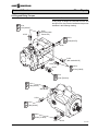
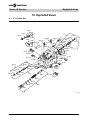
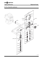
1
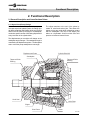
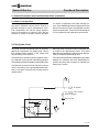
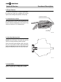
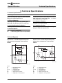
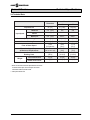
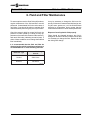
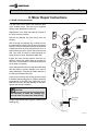
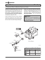
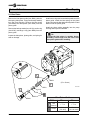
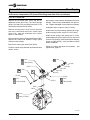
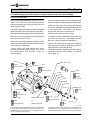
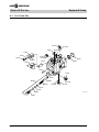
saue
Series 45
Axial Piston
Open Circuit Pumps
Service Manual
saue
Series 45 Service
Introduction
1. Introduction
1.1 Using This Manual
This manual includes information for the normal
operation, maintenance, and service of the Series 45
family of open circuit pumps. The manual includes a
description of the units and their individual components, troubleshooting information, adjustment instructions and minor repair procedures. Unit warranty obligations should not be affected if maintenance, adjustment and minor repairs are performed
according to the procedures described in this manual.
Many service and adjustment activities can be performed without removing the unit from the vehicle or
machine. However, adequate access to the unit must
be available, and the unit must be thoroughly cleaned
before beginning maintenance, adjustment, or repair
activities. Since dirt and contamination are the greatest enemies of any type of hydraulic equipment,
cleanliness requirements must be strictly followed.
This is especially important when changing the system filter and during adjustment and repair activities.
A worldwide network of Sauer-Sundstrand Authorized Service Centers is available should repairs be
needed. Contact any Sauer-Sundstrand Authorized
Service Center for details. A list of all Service Centers can be found in bulletin BLN-2-40527, or in
brochure SAW (Ident. No. 698266).
1.2 Safety Precautions
Always consider safety precautions before beginning a service procedure. Protect yourself and
others from injury.
The following general precautions should be taken
into consideration whenever servicing a hydrostatic system.
Disable Work Function
Fluid Under High Pressure
WARNING
Certain service procedures may require the
vehicle / machine to be disabled (wheels raised
off the ground, work function disconnected,
etc.) while performing them in order to prevent
injury to the technician and bystanders.
Flammable Cleaning Solvents
WARNING
Some cleaning solvents are flammable. To
avoid possible fire, do not use cleaning solvents in an area where a source of ignition
may be present.
WARNING
Use caution when dealing with hydraulic
fluid under pressure. Escaping hydraulic fluid
under pressure can have sufficient force to
penetrate your skin causing serious injury.
This fluid may also be hot enough to cause
burns. Serious infection or reactions can
develop if proper medical treatment is not
administered immediately.
Personal Safety
WARNING
Proper safety equipment, including safety
glasses, should be used at all times.
Copyright ©1999, Sauer-Sundstrand Company, All Rights Reserved.
2
Printed in U.S.A. 0899H
saue
Series 45 Service
Introduction
Contents
1. Introduction .............................................................................................................................................. 2
1.1 Using This Manual .............................................................................................................................. 2
1.2 Safety Precautions .............................................................................................................................. 2
1.3 Symbols Used in Sauer-Sundstrand Literature ................................................................................... 5
2. Functional Description ............................................................................................................................. 6
2.1 General Description and Cross Sectional Views ................................................................................ 6
2.1.1 Open Circuit Pump Design ........................................................................................................ 6
2.1.2 Basic Pump Operation .............................................................................................................. 7
2.2 The System Circuit .............................................................................................................................. 7
2.3 Pump Features ................................................................................................................................... 8
2.3.1 Displacement Limiters ............................................................................................................... 8
2.3.2 Auxiliary Mounting Pads ............................................................................................................ 8
2.3.3 Input Shafts ............................................................................................................................... 8
2.5 Pump Control Options ........................................................................................................................ 9
2.5.1 Pressure Compensator (PC) Control ........................................................................................ 9
2.5.2 Load Sensing (LS) Control ...................................................................................................... 10
3. Technical Specifications ......................................................................................................................... 11
3.1 General Specifications ...................................................................................................................... 11
3.1.1 Design ..................................................................................................................................... 11
3.1.2 Type of Mounting ..................................................................................................................... 11
3.1.3 Auxiliary Mounting Pad Options .............................................................................................. 11
3.1.4 Control Options ....................................................................................................................... 11
3.1.5 Port Connections ..................................................................................................................... 11
3.1.6 Direction of Rotation ................................................................................................................ 11
3.1.7 Installation Position ................................................................................................................. 11
3.2 Circuit Diagrams ............................................................................................................................... 11
3.3 Hydraulic Parameters ....................................................................................................................... 12
3.3.1 Inlet Pressure .......................................................................................................................... 12
3.3.2 Pressure Compensator Valve Setting ...................................................................................... 12
3.3.3 Case Pressure ......................................................................................................................... 12
3.3.4 Hydraulic Fluid ......................................................................................................................... 12
3.3.5 Temperature Range ................................................................................................................. 12
3.3.6 Fluid Viscosity Limits ............................................................................................................... 12
3.3.7 Filtration ................................................................................................................................... 12
3.4 Technical Data .................................................................................................................................. 13
4. Pressure Measurement ........................................................................................................................... 14
4.1 Required Tools .................................................................................................................................. 14
4.2 Port Locations and Pressure Gauge Installation .............................................................................. 14
4.2.1 57 cc Frame Size .................................................................................................................... 14
4.2.2 74 cc Frame Size .................................................................................................................... 15
5. Initial Start-up Procedures ..................................................................................................................... 16
6. Fluid and Filter Maintenance .................................................................................................................. 17
7. Troubleshooting ...................................................................................................................................... 18
7.1 Excessive Noise and / or Vibration ................................................................................................... 18
7.2 System Operating Hot ...................................................................................................................... 18
7.3 Actuator Response is Sluggish ......................................................................................................... 18
7.4 Low Pump Output Flow ..................................................................................................................... 19
7.5 Pressure Compensator Not Reaching PC Setting ............................................................................ 20
7.6 High Inlet Vacuum ............................................................................................................................. 20
7.7 Pressure or Flow Instability ............................................................................................................... 20
3
saue
Series 45 Service
Introduction
Contents (continued)
8. Adjustments ............................................................................................................................................
8.1 Pressure Compensator (PC) Control Adjustments ...........................................................................
8.1.1 57 cc Frame Size ....................................................................................................................
8.1.2 74 cc Frame Size ....................................................................................................................
8.2 Load Sensing (LS or LB) Control Adjustment ...................................................................................
8.2.1 57 cc Frame Size ....................................................................................................................
8.2.2 74 cc Frame Size ....................................................................................................................
8.3 Displacement Limiter Adjustment ....................................................................................................
9. Minor Repair Instructions .......................................................................................................................
9.1 Shaft Seal Replacement ...................................................................................................................
9.2 Displacement Piston and Maximum Displacement Limiter ...............................................................
9.3 Bias Piston .......................................................................................................................................
9.4 Auxiliary Pads ...................................................................................................................................
9.5 Control Personality Conversion, 57cc Only .......................................................................................
9.6 Pressure Compensator (PC) Control Pilot Stage and Gain Orifice ...................................................
9.6.1 57 cc Frame Size ....................................................................................................................
9.6.2 74 cc Frame Size ....................................................................................................................
9.7 Load Sensing (LS or LB) Control or Pressure Compensator (PC) Second Stage ............................
9.7.1 57 cc Frame Size ....................................................................................................................
9.7.2 74 cc Frame Size ....................................................................................................................
9.8 Plug and Fitting Torques ...................................................................................................................
9.8.1 57 cc Frame Size ....................................................................................................................
9.8.2 74 cc Frame Size ....................................................................................................................
10. Exploded Views .....................................................................................................................................
10.1 57 cc Frame Size ..........................................................................................................................
10.2 74 cc Frame Size ..........................................................................................................................
10.3 Auxiliary Pad Adapters ...................................................................................................................
4
22
22
22
23
24
24
25
26
28
28
29
30
31
32
33
33
34
35
35
36
37
37
38
40
40
42
46
saue
Series 45 Service
Introduction
1.3 Symbols Used in Sauer-Sundstrand Literature
DANGER! May result in injury.
Lubricate with hydraulic fluid.
May result in immediate or premature damage.
Apply grease / petroleum jelly.
Reusable part
Apply locking compound.
Nonreusable part, use a new part.
Inspect for wear or damage.
Non-removable item
Clean area or part.
“OR” in drawing – either option may exist.
Be careful not to scratch or damage.
Measurement required.
Note correct orientation.
Flatness specification
Mark orientation for reinstallation.
Parallelism specification
Torque specification
External hex head
Press in.
Internal hex head
Pull out with tool.
Torx head
Use installation sleeve / cone "bullet".
Tip, helpful suggestion
The symbols above can be found in the illustrations
and text of this manual. They are intended to
communicate helpful information at the point where
it is most useful to the reader.
In most instances, the appearance of the symbol itself
denotes its meaning. The legend above is provided to
define each symbol and explain its purpose.
5
saue
Series 45 Service
Functional Description
2. Functional Description
2.1 General Description and Cross Sectional Views
2.1.1 Open Circuit Pump Design
Sauer-Sundstrand Series 45 open circuit pumps convert input torque into hydraulic power. A rotating cylinder block containing axial pistons which are forced in
and out of their bores by the angle of a swashplate,
results in a specific amount of fluid being displaced for
every revolution of the cylinder block.
The slipper attaches to the end of the piston by
means of a ball and socket joint. This allows the
slipper to tilt at any angle while maintaining contact
with the swashplate. The face of the slipper pad
slides on a hydrostatic fluid film which uses fluid
pressure to balance internal forces.
The displacement per revolution will change as the
swashplate angle changes. The swashplate angle is
controlled by the displacement piston. The bias piston
acts to return the pump swashplate to max angle.
Displacement Piston
Cylinder Block Kit
Swashplate
Tappered Roller
Bearing
Tappered Roller
Bearing
Shaft Seal
Valve Plate
Slipper
Bias Piston
Piston
P101 038E
6
saue
Series 45 Service
Functional Description
2.1 General Description and Cross Sectional Views (continued)
2.1.2 Basic Pump Operation
Series 45 pumps utilize a cradle swashplate design with a hydraulic control piston. Control is
provided through a built-in compensator valve.
This compensator will shift the pump displacement from maximum to minimum when the set
pressure is reached. Controls are also available
for remote compensators and load sensing systems. An available displacement adjustment screw
allows the maximum flow to be adjusted to match
system requirements. These controls are designed
for low hysteresis and responsive performance.
2.2 The System Circuit
The pump receives fluid directly from the reservoir
without the requirement of a charge pump. Fluid is
then pumped under pressure to the system and
returns directly to the reservoir.
When the pump’s automatic control is activated, fluid
is ported to the displacement piston. This action
destrokes the swashplate (reduces pump displacement) to obtain the desired pump flow.
The speed of the actuator (cylinder, hydraulic motor,
etc.) depends on the volume of fluid being pumped.
The operating pressure depends on the actuator load.
The control can position the swashplate at any angle
between it’s maximum and zero displacement to
provide the pump flow necessary to maintain the
setting of the control.
If the actuator is to be reversed, a direction control
valve is necessary as the pump swashplate operates on one side of neutral only and the pump is
unidirectional.
To System
From System
Heat Exchanger
B
X
Return Filter
M2
M4
L1, L2
S
P101 039E
7
saue
Series 45 Service
Functional Description
2.3 Pump Features
To meet the requirements of various applications,
the Series 45 pumps are available with various
options which change the operation of the pump.
Adjustment Screw
2.3.1 Displacement Limiters
Series 45 pumps are available with an optional maximum displacement limiter. This mechanical stop can
limit the maximum displacement of the pump to any
value from maximum to 75% displacement.
Lock Nut
P101 040E
2.3.2 Auxiliary Mounting Pads
Auxiliary mounting pads are available for all radial
ported Series 45 pumps. These pads are typically
used for mounting auxiliary hydraulic pumps.
Since the auxiliary pad operates under case pressure, an o-ring must be used to seal the auxiliary
pump mounting flange to the pad. The driving coupling is lubricated by oil from the main pump case.
P101 041
2.3.3 Input Shafts
Series 45 pumps are available with a variety of
splined, straight keyed, and tapered end shafts.
8
saue
Series 45 Service
Functional Description
2.5 Pump Control Options
2.5.1 Pressure Compensator (PC) Control
The pressure compensator control is designed to
maintain a constant pressure in the hydraulic circuit
as flow varies.
When the system pressure at the pump outlet drops
below the compensator setting, the control will increase the pump displacement to maximum (maximum flow). Once the system pressure reaches the
compensator setting, the control will regulate pump
displacement to produce an output flow which will
maintain system pressure at the compensator setting.
Gain - bar [psi] per turn
PC
nd
2
Stage
57 cc
74 cc
88.94 [1290]
42.06 [610]
17.93 [260]
---------T101 092E
The pressure compensator setting is adjustable. The
setting range for the pressure compensator is from
100 to 280 bar [1450 to 4060 psi]. Refer to Section
8, page 22, for adjustment procedures.
Note: On 57cc pumps built after serial number
A-98-21-XXXXX, tamper resistant hardware is installed on the PC & second stage adjustment screws.
This will allow only one complete clockwise turn from
the original factory setting.
Second Stage Adjustment
Screw
PC Adjustment
Screw
57 cc
74 cc
PC Adjustment
Screw
P101 042E
9
saue
Series 45 Service
Functional Description
2.5 Pump Control Options (continued)
2.5.2 Load Sensing (LS) Control
The load sensing control is designed to match pump
outlet flow and pressure with system demand.
When the control valve is “centered,” the load sensing
port on the pump is drained to the reservoir through a
bleed orifice located either in the control valve or the
pump housing. This maintains a standby pressure at
the pump outlet equal to the load sense setting.
When the external control valve is actuated, the load
sensing port sees the load pressure. The pump
control then adjusts the pump output flow to maintain
a constant pressure drop (equal to the load sensing
setting) across the external control valve. The pump
thereby provides flow to the load as demanded by the
external control valve position.
The load sensing setting is adjustable. The setting
range for the load sensing control is from 10 to 30 bar
[145 to 435 psi]. Refer to section 8, page 24, for
adjustment procedures.
Gain - bar [psi] per turn
57 cc
74 cc
PC
88.94 [1290]
42.06 [610]
LS
17.93 [260]
17.24 [250]
T101 093E
Note: On 57cc pumps built after serial number
A-98-21-XXXXX, tamper resistant hardware is installed on both the PC & LS adjustment screws. This
will allow only one complete counter clockwise turn
from original factory setting.
LS Port
PC Adjustment
Screw
57 cc
LS Adjustment Screw
74 cc
PC Adjustment
Screw
LS Port
P101 043E
10
saue
Series 45 Service
Technical Specifications
3. Technical Specifications
3.1 General Specifications
3.1.1 Design
3.1.5 Port Connections
Open circuit axial piston pumps of cradle swashplate
design with variable displacement.
Inlet and pressure ports: SAE Flange Ports, Code 61
Axial (end) ports or radial (side) ports All other:
SAE straight thread o-ring boss
3.1.2 Type of Mounting
SAE flange, Size C (SAE J744) mounting pad
SAE flange, Size B optional for 57cc pump only
3.1.6 Direction of Rotation
3.1.3 Auxiliary Mounting Pad Options
3.1.7 Installation Position
SAE flange, Size A, B, B-B, or C
Installation position discretionary. The housing must
always be filled with hydraulic fluid.
3.1.4 Control Options
PC:
LS:
Clockwise or counterclockwise
Pressure Compensator
Load Sensing (with Pressure Compensator)
3.2 Circuit Diagrams
Series 45 74 cc variable displacement pump
with pressure compensator / load sensing
control
Series 45 57 cc variable displacement pump
with pressure compensator / load sensing
control
B
B
X
*
X
*
M2
M2
M4
*optional
M4
L1,L2
S
P101 103
*optional
L1,L2
S
P101 102
Ports:
B
S
L1, L2
X
M2
M4
=
=
=
=
=
=
Main pressure line
Suction line
Case drain lines
Load sense line
Gauge port for port "B"
Gauge port - servo pressure
Ports:
B
S
L1, L2
X
M2
M4
=
=
=
=
=
=
Main pressure line
Suction line
Case drain lines
Load sense line
Gauge port for port "B"
Gauge port - servo pressure
11
saue
Series 45 Service
Technical Specifications
3.3 Hydraulic Parameters
3.3.1 Inlet Pressure
3.3.5 Temperature Range1
Minimum pressure, continuous = 0.8 bar absolute
[23.2 in Hg]
Intermittent, cold start
Continuous
Maximum
(at reduced maximum pump speed)
Minimum pressure, cold start = 0.5 bar absolute
[14.8 in Hg]
=
=
=
- 40° C [- 40° F]
82° C [180° F]
104° C [220° F]
(at the hottest point, i.e. drain line)
1. Hydraulic fluid viscosity must be maintained within the prescribed limits.
3.3.2 Pressure Compensator Valve Setting
3.3.6 Fluid Viscosity Limits
Minimum pressure: 100 bar [1450 psi]
mm2/s (cSt)
SUS (Saybolt Universal Seconds)
Maximum continuous: 0.5 bar [7 psi] Above inlet
Intermittent: 2 bar [29 psi] Cold start
n
n
n
n
58 min. continuous
47 intermittent
500 max. continuous
4700 intermittent, cold start
3.3.4 Hydraulic Fluid
3.3.7 Filtration
Refer to Sauer-Sundstrand publication BLN-9887 or
697581. Refer to publication ATI-E 9101 for information relating to biodegradable fluids.
Required cleanliness level: ISO 4406 Class 18/13 or
better. Refer to Sauer-Sundstrand publication BLN9887 or 697581 and ATI-E 9201.
Maximum pressure: 280 bar [4060 psi]
3.3.3 Case Pressure
12
min
min
max
max
=
9
=
6.4
= 110
= 1000
saue
Series 45 Service
Technical Specifications
3.4 Technical Data
Dimension
Frame Size
057
074
cm [in ]
57 [3.48]
74 [4.52]
Minimum
min-1 (rpm)
500
500
Rated*
min-1 (rpm)
2600
2400
Maximum*
min-1 (rpm)
3200**
2800**
Maximum (Peak) Working Pressure
bar [psi]
350 [5075]
350 [5075]
Continuous Working Pressure
bar [psi]
280 [4060]
280 [4060]
Flow at Rated Speed
l/min
[US gal/min]
148.2
[39.5]
177.6
[47.4]
Theoretical Input Torque
at Maximum Displacement
Nm/bar
[lbf·in/1000 psi]
0.907
[554]
1.178
[720]
Mass Moment of Inertia of the Internal
Rotating Parts
kg·m2
[lbf·ft2]
0.0043
[0.1014]
0.0063
[0.1500]
Axial Ported Units
kg [lb]
24 [53]
29 [63]
Radial Ported Units
kg [lb]
27 [60]
36 [80]
Displacement
Input Speed
Weight
3
3
T101 119E
* Refer to General Technical Specifications in Series
45 Axial Piston Open Circuit Pumps Technical
Information Manual, BLN-10128.
** With pressurized inlet.
13
saue
Series 45 Service
Pressure Measurement
4. Pressure Measurement
4.1 Required Tools
The service procedures described in this manual for
Series 45 pumps can be performed using common
mechanic’s hand tools. Special tools, if required are
shown. Pressure gauges should be calibrated frequently to ensure accuracy. Snubbers are recommended to protect pressure gauges.
4.2 Port Locations and Pressure Gauge Installation
The following sections list the gauge ports for each
frame size. The recommended pressure gauge and
fitting are also specified. Outline drawings showing
port locations follow the tables.
4.2.1 57 cc Frame Size
M2
System
Pressure
300 bar or 5000 psi gauge
7/16 — 20 o-ring Fitting
L1 Case
L2 Pressure
10 bar or 100 psi gauge
7/8 — 14 o-ring Fitting (057)
M4
Control
Piston
300 bar or 5000 psi gauge
7/16 — 20 o-ring Fitting
X1 LS Signal
300 bar or 5000 psi gauge
Tee into LS Signal Line
7/16 — 20 o-ring Fitting
LS Signal
Port X*
Remote PC Signal
Case Drain
Port L2
Servo Pressure Gauge Port
Port M4
System Output
Port B
System Inlet
Port S
*This port is plugged on
pumps with PC control
Case Drain
Port L1
System Pressure Gauge Port
Port M2
Base Unit Shown with PC / LS Control and Axial End
Cap Ports (LH Rotation)
14
P101 050E
saue
Series 45 Service
Pressure Measurement
4.2 Port Locations and Pressure Gauge Installation (continued)
4.2.2 74 cc Frame Size
M2
System
Pressure
300 bar or 5000 psi gauge
7/16 — 20 o-ring Fitting
L1 Case
L2 Pressure
10 bar or 100 psi gauge
7/8 — 14 o-ring Fitting (074)
M4
Control
Piston
300 bar or 5000 psi gauge
7/16 — 20 o-ring Fitting
X1 LS Signal
300 bar or 5000 psi gauge
Tee into LS Signal Line
7/16 — 20 o-ring Fitting
Case Drain
Port L1
LS Signal
Port X
LS Signal
Port X1
Servo Pressure Gauge Port
Port M4
System Pressure Gauge Port
Port M2
Case Drain
Port L2
Base Unit with PC/LS Control and Axial End Cap
Ports Shown
P101 047E
15
saue
Series 45 Service
Initial Start-up Procedures
5. Initial Start-up Procedures
The following start-up procedure should always be
followed when starting-up a new Series 45 installation or when restarting an installation in which the
pump has been removed.
WARNING
The following procedure may require the
vehicle/machine to be disabled (wheels raised
off the ground, work function disconnected,
etc.) while performing the procedure in order
to prevent injury to the technician and
bystanders. Take necessary safety precautions before moving the vehicle/machine.
Prior to installing the pump, inspect the units for
damage incurred during shipping and handling. Make
certain all system components (reservoir, hoses,
valves, fittings, heat exchanger, etc.) are clean prior
to filling with fluid.
The pump should be connected to the prime mover
so that the centers of both shafts are aligned. Incorrect alignment may result in eventual damage to the
drive shaft, drive shaft bearings, or the drive shaft
seal which can cause external oil leakage.
Fill the main pump housing with clean hydraulic fluid
prior to start up. Fill by pouring filtered oil directly into
the upper most case drain hole.
Fill the reservoir with recommended hydraulic fluid.
Fluid should always be filtered through a 25 micron
filter prior to entering the reservoir. Never reuse
hydraulic fluid.
16
The inlet line leading from the pump to the reservoir
must be filled prior to start up. Check inlet line for
properly tightened fittings and be certain it is free of
restrictions and air leaks.
To ensure the pump stays filled with oil, the case
drain line should be installed in the upper most
case drain port.
Follow recommendations in the vehicle / machine
operator’s manual for prime mover start up procedures.
Install a gauge at port M2 to monitor system pressure
during start up.
Jog the prime mover or run at the lowest possible
speed until system pressure builds to normal levels (minimum 11 bar [160psi]). Once system
pressure is established, increase the speed to full
operating RPM. If system pressure is not maintained, shut down the prime mover, determine the
cause, and take corrective action. Refer to Troubleshooting, page 18.
Operate the hydraulic system for at least fifteen (15)
minutes under light load conditions. It may be necessary to check and adjust control settings after installation. Refer to Adjustments, page 22. Shut down the
prime mover and remove the pressure gauge. Check
the fluid level in the reservoir, add if necessary.
The pump is now ready for operation.
saue
Series 45 Service
Fluid and Filter Maintenance
6. Fluid and Filter Maintenance
To ensure optimum service life of Series 45 products,
regular maintenance of the fluid and filter must be
performed. Contaminated fluid is the main cause of
unit failure. Care should be taken to maintain fluid
cleanliness while performing any service procedure.
It may be necessary to change the fluid more frequently if it becomes contaminated with foreign matter (dirt, water, grease, etc.) or if the fluid has been
subjected to temperature levels greater that the
recommended maximum. Never reuse hydraulic fluid.
Check the reservoir daily for proper fluid level, the
presence of water (noted by a cloudy to milky appearance or free water in the bottom of the reservoir),
and rancid fluid odor (indicating excessive heat). If
either of these conditions occur change the fluid and
filter immediately.
Dispose of used hydraulic fluid properly.
Filters should be changed whenever the fluid is
changed or whenever the filter indicator shows that
it is necessary to change the filter. Replace all fluid
lost during filter change.
It is recommended that the fluid and filter be
changed per the vehicle / machine manufacturer’s
recommendations or at the following intervals:
Reservoir Type
Maximum Oil Change
Interval
Sealed
2000 Hours
Breather
500 Hours
T101 097E
17
saue
Series 45 Service
Troubleshooting
7. Troubleshooting
7.1 Excessive Noise and / or Vibration
Description
Item
Action
1. Check oil in reservoir.
Insufficient hydraulic fluid will lead to
cavitation.
Fill the reservoir to proper level.
2. Check for air in system.
Noisy, erratic control.
Purge air and tighten fittings. Check
inlet for leaks.
3. Check pump inlet pressure / vacuum.
Erratic behavior, low output flow.
Correct pump inlet pressure / vacuum
conditions.
4. Inspect shaft couplings.
A loose or incorrect shaft coupling
will cause excessive noise and/or
vibration.
Repair or replace coupling and check
that correct coupling is being used.
5. Inspect shaft alignment.
Misaligned shafts will create excessive frictional noise and/or vibration.
Correct shaft misalignment.
6. Hydraulic oil improper viscosity.
Hydraulic oil viscosity above acceptable limits will cause cavitation at
start up.
Replace existing fluid with the appropriate viscosity grade fluid. See Hydraulic
Fluids, Series 45 Technical Information
Manual, BLN-10128.
Description
Action
1. Check oil in reservoir.
Insufficient amount of hydraulic oil
will not meet cooling demands of
system.
Fill the reservoir to proper level. Verify
proper size of reservoir.
2. Inspect heat exchanger.
Heat exchanger not sufficiently cooling system.
Check air flow and input air temperature for the heat exchanger. Clean,
repair, or replace heat exchanger. Verify
proper size of heat exchanger.
3. Check external system relief valve setting.
Relief valve setting below PC setting
will create heat.
Adjust external system relief valve
setting.
4. Check pump inlet pressure/vacuum.
High inlet vacuum will create heat.
Correct inlet pressure / vacuum conditions.
7.2 System Operating Hot
Item
7.3 Actuator Response is Sluggish
Item
Description
1. Check external system relief valve setting.
Low external relief valve setting will
slow down system.
Adjust external relief valve setting.
2. Check PC and LS control
setting.
Low PC setting will prevent the pump
from achieving full stroke.
Adjust PC and LS setting.
3. Check LS control signal
pressures.
Incorrect LS signal will not allow pump
to operate correctly.
Inspect system, ensure that proper LS
signal is transmitted to the pump.
4. PC control not operating
properly.
PC control with abnormal wear or
contamination will not operate
properly.
Flush screen in PC cartridge to remove
contamination or replace abnormally
worn spool.
18
Action
saue
Series 45 Service
Troubleshooting
7.3 Actuator Response is Sluggish (continued)
Item
Description
Action
5. Internal system leaks.
Worn internal parts will not allow the
pump to operate properly.
Repair as required.
6. Hydraulic oil viscosity
above acceptable limits.
Oil viscosity above acceptable limits
or low oil temperature will not allow
the pump to fill or control to operate
properly.
Allow system to warm up before operation or use fluid with the appropriate viscosity grade for expected operating temperatures. See Hydraulic
Fluids, Series 45 Technical Information Manual, BLN-10128.
7. Check system valving.
Malfunctioning valve may not allow
system to respond.
Repair or replace system valving.
8. Check pump case pressure.
High case pressure will cause the
system to be sluggish.
Correct case drain line restrictions.
9. Check pump inlet pressure / vacuum.
High inlet vacuum will cause cavitation and generate heat.
Correct inlet pressure conditions.
7.4 Low Pump Output Flow
Item
Description
Action
1. Check oil in reservoir.
Insufficient hydraulic oil level.
Fill the reservoir to proper level.
2. Hydraulic oil viscosity
above acceptable limits.
Oil viscosity above acceptable limits
or low oil temperature will not allow
the pump to fill or control to operate
properly.
Allow system to warm up before operation or use fluid with the appropriate
viscosity grade for expected operating
temperatures. See Hydraulic Fluids,
Series 45 Technical Information Manual,
BLN-10128.
3. Check external system relief valve setting.
External relief valve set below PC
setting will cause low flow.
Correct external relief valve setting.
4. Check PC and LS control
setting.
Low PC setting will prevent the pump
from achieving full stroke. Low LS
setting will prevent adequate flow.
Adjust PC and LS setting. See Adjustments, page 22.
5. Check pump inlet pressure / vacuum.
High inlet vacuum will cause cavitation and decrease flow.
Correct inlet pressure conditions.
6. Check input speed.
Low input speeds decrease flow.
Adjust input speed.
7. Check pump displacement
limiter.
Pump displacement limiter may be
set below desired flow rate.
Adjust displacement limiter to the appropriate setting. See Adjustments,
page 26.
8. Check pump rotation.
Incorrect rotational configuration will
cause low flow.
Use pump with appropriate rotational
configuration.
9. Check pilot orifice in
port X.
Restricted control orifice will limit
output flow.
Inspect and clean control orifice.
10. Verify bleed orifice plug is
installed (serial numbers
prior to A-97-52-XXXX).
If plug is missing, control will not
perform correctly.
Install bleed orifice plug (C111).
See Minor Repair page 33.
19
saue
Series 45 Service
Troubleshooting
7.5 Pressure Compensator Not Reaching PC Setting
Item
Description
Action
1. Check PC control setting.
Pump will not compensate to pressure settings.
Adjust PC to appropriate setting.
2. Check external relief
valve.
PC control cannot be set above an
external relief valve setting.
Adjust the external relief valve to the
appropriate setting.
3. Inspect compensator
spring.
Broken, damaged, or missing spring
will cause erratic operation.
Replace spring.
4. Inspect PC poppet (57cc),
or spool (74cc) for wear.
Abnormal wear of the PC poppet
or spool will allow internal leakage
in the control.
Replace PC cartridge or spool.
5. Inspect compensator
spool.
Improper orientation will result in
poor operation.
Correct orientation of spool.
6. Check PC control for contamination.
Spool or poppet is held open by
contaminants.
Clean PC control components and rid
system of contamination.
7. Verify bleed orifice plug is
installed (serial numbers
prior to A-97-52-XXXX).
If plug is missing, control will not
perform correctly.
Install bleed orifice plug (C111).
See Minor Repair page 33.
Description
Action
7.6 High Inlet Vacuum
Item
1. Check oil temperature.
Cold oil has a higher viscosity.
Allow system to warm up before operation.
2. Inspect inlet screen.
Restriction will cause high vacuum.
Remove restriction / blockage.
3. Check inlet piping.
Too many fittings, bends, or long
piping will cause high vacuum.
Eliminate fittings to make path more
direct.
4. Hydraulic oil improper
viscosity.
Hydraulic oil viscosity above acceptable limits will cause cavitation.
Replace existing fluid with the appropriate viscosity grade fluid. See Hydraulic Fluids, Series 45 Technical
Information Manual, BLN-10128.
7.7 Pressure or Flow Instability
Item
Description
Action
1. Air in system.
Air in system will cause erratic
operation.
Activate PC, allowing system to bleed
air. Check inlet line for leaks.
2. Check control spools.
Sticking control spools.
Inspect spools for free movement in
bore. Clean or replace as needed.
3. Check external relief
valve and PC setting.
Insufficient pressure differential between pump and external relief valve.
Adjust external relief valve or PC control
settings to appropriate level.
4. Check external relief
valve.
Chattering external relief valves may
be causing unstable feedback to
pump.
Adjust or replace relief valve.
5. Check gain orifice-plug
(57 cc only).
Obstructed gain orifice-plug option
may cause instability.
Clear or change gain orifice-plug.
20
saue
Series 45 Service
Troubleshooting
Notes:
21
saue
Series 45 Service
Adjustments
8. Adjustments
8.1 Pressure Compensator (PC) Control Adjustments
8.1.1 57 cc Frame Size
WARNING
Do not make adjustments or disconnect any
hoses until all residual pressure in the system
circuit has been released.
Take necessary precautions to secure the work
function of the machine to prevent injury while
performing this procedure.
The pressure compensator setting is indicated in the
pump model code. Refer to the Technical Information Manual BLN-10128 for more information.
Install a pressure gauge in port M2 to measure system
pressure. Install a pressure gauge in drain port L1 or
L2 to measure case pressure. If a remote PC control
is used, disconnect the signal line, cap it, and plug the
port. Refer to Pressure Measurement, page 14.
Install a pilot hose (6mm [0.25 in] diameter minimum) at port X connecting to the reservoir to drain
the remote PC port.
Note: Failure to drain port X (spring cavity) to reservoir
may cause additional back pressure on the PC spring,
resulting in pressure settings above the desired specification. It is recommended that this procedure be
used on all Series 45, 57cc pumps, however it is
particularly vital to 1999 and newer units due to hardware changes associated with the PC cartridge.
Start the prime mover and run at normal speed. While
securing the second stage adjustment screw, loosen
the seal locknut. Turn the second stage adjustment
screw1 until a the gauge at port M22 reads 15 bar
[220psi]. Clockwise rotation of the screw will increase
pressure, counterclockwise rotation will decrease.
While holding the position of the second stage adjustment screw, torque the seal locknut to 23 Nm [17 lbf•ft].
Shut down the prime mover. Disconnect the pilot
hose installed at port X and reinstall the plug.
Start the prime mover and run at normal speed.
Operate a hydraulic function to its full extension, loading the pump at maximum pressure and zero flow.
While securing the PC adjustment screw, loosen
the seal locknut. Turn the PC adjustment screw1
until the desired setting is indicated on the pressure gauge at port M23. Clockwise rotation will
increase pressure, counterclockwise rotation will
decrease. If the pressure does not increase, an
external system relief valve may need to be adjusted. An external system relief valve should be
set above the PC setting for proper operation.
While holding the position of the PC adjustment
screw, torque the seal locknut to 23 Nm [17 lbf•ft].
Stop the prime mover, remove the pressure
gauges, and return the system to its normal operating configuration.
Remote PC Port
Second Stage
Adjustment Screw
13 mm
PC Adjustment Screw
13 mm
Second Stage
Adjustment
Seal-Lock Nut
13 mm
PC Adjustment
Seal Lock Nut
13 mm
23 Nm [17 lbf ft]
23 Nm [17 lbf ft]
Port X
P101 046E
1. Pumps with serial number greater than A-98-21-XXXX will have
tamper resistant hardware installed on both the PC and second
stage adjustments. This will only allow one complete clockwise
turn from the original factory setting.
22
2. The second stage setting is referenced to the pressure at port X.
During this procedure port X is vented to reservoir.
3. PC setting is referenced to case pressure. Subtract case
pressure from system pressure to compute the actual setting.
saue
Series 45 Service
Adjustments
8.1 Pressure Compensator (PC) Control Adjustments (continued)
8.1.2 74 cc Frame Size
WARNING
Do not make adjustments or disconnect any
hoses until all residual pressure in the system
circuit has been released.
Take necessary precautions to secure the work
function of the machine to prevent injury while
performing this procedure.
Install a pressure gauge in port M2 to measure
system pressure. Install a pressure gauge in case
drain port L1 or L2 to measure case pressure. Refer
to Pressure Measurement, page 14.
Loosen the PC set screw and turn the adjustment
screw counter clockwise to release the spring
pressure. Turn until the end of the screw is flush
with the housing.
Start the prime mover and allow fluid to reach normal
operating temperature.
Operate the prime mover at normal speed.
Operate a hydraulic function to its full extension,
loading the pump at maximum pressure and zero flow.
Turn the PC adjustment screw until system pressure
reaches the desired value, as indicated on the
gauge at port M21. Clockwise rotation will increase
the setting, counterclockwise rotation will decrease.
If the pressure does not increase, an external system relief valve may need adjustment. External
system relief valve should be set above the PC
setting for proper operation.
While holding the position of the PC adjustment
screw, torque the setscrew to 6.8 Nm [5 lbf•ft].
Stop the prime mover and remove the pressure
gauges installed at port M2, and case drain port L1 or
L2. Replace the port plugs.
PC Set Screw
4mm
6.8 Nm [5 lbf•ft]
PC Adjustment Screw
6mm
P101 053E
1. PC setting is referenced to case pressure. Subtract case
pressure from system pressure to compute the actual setting.
23
saue
Series 45 Service
Adjustments
8.2 Load Sensing (LS or LB) Control Adjustment
8.2.1 57 cc Frame Size
WARNING
Do not make adjustments or disconnect any
hoses until all residual pressure in the system
circuit has been released.
Take necessary precautions to secure the work
function of the machine to prevent injury while
performing this procedure.
pump, but keep the system pressure below the PC
set point. While watching the pressure gauges, turn
the LS adjustment screw1 until the desired pressure
differential between port M2 (system pressure) and
the remote PC port (LS signal) is achieved2. Clockwise rotation will increase the setting, counterclockwise rotation will decrease.
While holding the position of the adjustment screw,
torque the seal locknut to 23 Nm [27 lbf•ft].
Install a pressure gauge in port M2 to measure
system pressure. Install a pressure gauge in drain
port L1 or L2 to measure case pressure. Install a
pressure gauge in the remote PC port. If remote PC
is used, temporarily remove the remote PC signal
line and cap it. Leave the LS signal line connected.
Refer to Pressure Measurement, page 14.
Operate a hydraulic function to its full extension
loading the pump at maximum pressure and zero
flow. While securing the PC adjustment screw,
loosen the seal locknut. Turn the PC adjustment
screw1 until the desired setting is indicated on the
pressure gauge at port M23. Clockwise rotation will
increase the setting, counterclockwise rotation will
decrease. If the pressure does not increase, an
external system relief valve may need to be adjusted.
External system relief valve should be set above the
PC setting for proper operation.
Start the prime mover and allow fluid to reach normal
operating temperature.
While holding the position of the PC adjustment
screw, torque the seal locknut to 23 Nm [17 lbf•ft].
While securing the LS adjustment screw, loosen the
seal locknut. Slowly operate a hydraulic function
which will demand approximately half flow from the
Stop the prime mover, remove the pressure
gauges, and return the system to its normal operating configuration.
The LS or LB Setting is indicated in the pump model
code. Refer to the Technical Information Manual
BLN-10128 for more information.
PC Adjustment Screw
13 mm
PC Adjustment
Seal Lock Nut
13 mm
Remote PC Port
LS Adjustment Screw
13 mm
23 Nm [17 lbf•ft]
Port X
LS Signal
LS Adjustment
Seal-Lock Nut
13 mm
23 Nm [17 lbf•ft]
P101 048E
1. Pumps with serial number greater than A-98-21-XXXX will have
tamper resistant hardware installed on both the PC and second
stage adjustments. This will only allow one complete clockwise
turn from the original factory setting.
24
2. The LS setting is a differential pressure. Subtract pilot
pressure at the remote PC port from system pressure at port
M2 to compute the actual setting.
3. PC setting is referenced to case pressure. Subtract case
pressure from system pressure to compute the actual setting.
saue
Series 45 Service
Adjustments
8.2 Load Sensing (LS or LB) Control Adjustment (continued)
8.2.2 74 cc Frame Size
WARNING
Do not make adjustments or disconnect any
hoses until all residual pressure in the system
circuit has been released.
Take necessary precautions to secure the work
function of the machine to prevent injury while
performing this procedure.
The LS or LB Setting is indicated in the pump model
code. Refer to the Technical Information Manual,
BLN-10128 for more information.
Install a pressure gauge in port M2 to measure
system pressure. Install a pressure gauge in drain
port L1 or L2 to measure case pressure. Install a
pressure gauge in port X to measure LS signal
pressure. Leave the LS signal line connected,
using the opposite port for the gauge. Refer to
Pressure Measurement, page 14.
Start the prime mover and allow fluid to reach normal
operating temperature.
Loosen the LS locking set screw. Slowly operate a
hydraulic function which will demand approximately
half flow from the pump, but keep the system presPort X
3/16 in
12 Nm (9 lbf•ft)
sure below the PC set point. While watching the
pressure gauges, turn the LS adjustment screw until
the desired pressure differential between port M2
(system pressure) and port X (LS signal) is achieved1.
Clockwise rotation will increase the setting, counterclockwise rotation will decrease.
While holding the position of the adjustment screw,
torque the locking set screw to 6.8 Nm [5 lbf•ft].
Operate a hydraulic function to its full extension
loading the pump at maximum pressure and zero
flow. While securing the PC adjustment screw,
loosen the seal locknut. Turn the PC adjustment
screw until the desired setting is indicated on the
pressure gauge at port M22. Clockwise rotation will
increase the setting, counterclockwise rotation will
decrease. If the pressure does not increase, an
external system relief valve may need to be adjusted.
External system relief valve should be set above the
PC setting for proper operation.
While holding the position of the PC adjustment
screw, torque the locking set screw to 6.8 Nm [5 lbf•ft].
Stop the prime mover, remove the pressure
gauges, and return the system to its normal operating configuration.
LS Locking Set Screw
4mm
6.8 Nm (5 lbf•ft)
LS Adjustment Screw
6 mm
PC Locking Set Screw
4mm
6.8 Nm (5 lbf•ft)
PC Adjustment Screw
6 mm
P101 049E
1. The LS setting is a differential pressure. Subtract pilot
pressure at port X from system pressure at port M2 to compute
the actual setting.
2. PC setting is referenced to case pressure. Subtract case
pressure from system pressure to compute the actual setting.
25
saue
Series 45 Service
Adjustments
8.3 Displacement Limiter Adjustment
If equipped, the displacement limiter may be adjusted to achieve a desired maximum flow rate.
The preferred method for setting the displacement
limiter is to make adjustments while operating the
pump at full stroke on an appropriate test apparatus
equipped with a flow meter and system pressure
gauge. This allows the pump to be set to a specific
maximum flow rate under precise speed and pressure conditions. If test apparatus is not available, the
following procedure may be used to set an approximate maximum displacement. Remember to verify
that the displacement setting is appropriate by operating the pump in its application after adjustment.
To adjust the displacement limiter setting remove the
displacement piston bore plug with its o-ring. Loosen
the seal locknut and turn the displacement limiter
adjustment screw counter clockwise until the opposite end is flush with end of the displacement piston
bore plug. The setting is now at maximum displacement. Replace the o-ring and install the plug into the
pump housing. Torque the displacement piston plug
as indicated.
Turn the displacement limiter adjustment screw clockwise to set the desired maximum displacement. For
57cc pumps, the displacement is decreased by 5cc
per revolution of the displacement limiter adjustment
screw; for 74cc pumps, 6cc per revolution.
While holding the position of the displacement limiter
adjustment screw, torque the seal locknut.
WARNING
The seal lock nut must be torqued after every
adjustment to prevent an unexpected change
in pump output and to prevent external leakage
during unit operation.
Displacement Piston
Bore Plug
See Table
Displacement Limiter
Adjustment Screw
6 mm
Seal Locknut
19 mm
87 Nm [64 lbf ft]
(57 CC Shown)
Displacement Piston Bore Plug
57 cc
74 cc
Hex
Wrench
1 1/4 in
1 3/8 in
Torque
230 Nm
[170 lbf•ft]
176-244
[130-180lbf•ft]
T101 003E
26
P101 106E
saue
Series 45 Service
Adjustments
Notes:
27
saue
Series 45 Service
Minor Repair
9. Minor Repair Instructions
9.1 Shaft Seal Replacement
A lip type shaft seal is used in the Series 45 open
circuit variable pumps. This seal can be replaced
without major disassembly of the unit.
K010
Replacement of the shaft seal requires removal of
the pump from the machine.
Remove the retaining ring (item K010) from the
housing.
K020
After removing the retaining ring, carefully remove
the shaft seal (item K020) from the bore in the pump
housing. The face of the seal may be punctured with
a sharp instrument to aid in prying the seal out, or a
slide hammer type puller may be used to remove the
seal. Care must be taken to avoid damaging the
pump housing or shaft. Discard the shaft seal.
Inspect the pump housing and the new seal for
damage. Inspect the sealing area on the shaft for
rust, wear, or contamination. Polish the sealing area
on the shaft if necessary.
Use a seal protection sleeve or wrap the end of shaft
with thin plastic to prevent damage to the seal lip
during installation. Lubricate the inside diameter of
the new seal with petroleum jelly.
Press the new seal into the housing just far enough
to clear the retaining ring groove. Keep the shaft seal
perpendicular to the shaft. The cupped side of the
shaft seal must face the shaft bearing. Do not damage the seal during installation.
CAUTION
Do not press the seal into the housing farther
than necessary to install the retaining ring.
The seal must not contact the shaft bearing.
Using the appropriate snap ring pliers, install the seal
retaining ring.
5.33 mm
[.21 in]
P101 051
28
saue
Series 45 Service
Minor Repair
9.2 Displacement Piston and Maximum Displacement Limiter
Remove the displacement piston bore plug
(item L020) with its o-ring. Discard the o-ring. Remove the displacement piston (item L010) from the
pump housing. If equipped with displacement limiter, loosen the seal lock nut (item L030), remove the
nut and limiter screw (item L040) from the displacement piston bore plug (item L020).
Install a new o-ring on the piston bore plug and, if
equipped, install the displacement limiter screw and
seal locknut. Adjust the displacement limiter. See
Adjustments, page 26. Install the piston bore plug
into the pump housing. Torque the displacement
piston plug as indicated.
Inspect the displacement piston for wear or damage.
WARNING
The seal lock nut must be torqued after every
adjustment to prevent an unexpected change
in pump output and to prevent external leakage during unit operation.
Lubricate the displacement control piston with hydraulic oil and install it into the pump housing with the
hole in the end of the piston facing the bore plug.
L010
L020
L020
(57cc Shown)
L040
L030
P101 052E
6 mm
19 mm
87 Nm [64 lbf ft]
Displacement Piston Bore Plug
57 cc
74 cc
Hex
Wrench
1 1/4 in
1 3/8 in
Torque
230 Nm
[170 lbf•ft]
176-244
[130-180lbf•ft]
L020
T101 003E
29
saue
Series 45 Service
Minor Repair
9.3 Bias Piston
Remove the bias piston guide (item B081) (with the
bias spring, bias piston, o-rings and backup washer)
from the pump housing. Remove the bias spring
(item B083) and bias piston (item B084) from the
piston guide.
Remove the backup washer (item K110), small o-ring
(item K100), and large o-ring (item B082) from the
piston guide.
Install new o-rings and a new backup washer on the
piston guide. Install the bias spring on the piston
guide. Lubricate the bias piston with hydraulic oil and
install it onto the piston guide.
Install the piston guide assembly into the pump
housing and torque as indicated.
TIP
To keep the bias piston in position during
assembly, hold a finger over the hole in the
bias piston guide when installing.
Inspect the bias piston, piston guide, and spring for
wear or damage.
B084
(57cc Shown)
P101 054E
B083
K110
K100
B082
Bias Piston Guide
B081
B081
57 cc
74 cc
Hex
Wrench
1 1/4 in
1 3/8 in
Torque
230 Nm
[170 lbf•ft]
176-244
[130-180 lbf•ft]
T101 003E
30
saue
Series 45 Service
Minor Repair
9.4 Auxiliary Pads
If installed, remove the screws retaining the auxiliary
pump (not shown), and remove the pump with its
sealing o-ring. Discard the o-ring. Remove the drive
coupling (item J140).
Remove the four screws (item J100) retaining the
pad adapter (item J080) to the pump end cap (six
screws are used for the SAE C pad). Discard the
two pad adapter o-rings (items J090, J095).
J140
J100
75 Nm
[55 lbf•ft]
Install the pad adapter with new o-rings1. Lubricate
o-rings with petroleum jelly before installation. Install
and torque the screws to 75 Nm [55 lbf•ft].
Install the drive coupling. If equipped, install the
auxiliary pump with new o-ring.
8 mm
J080
J0951
J090
P101 055E
1. Units with serial number prior to A97-42-XXXX do not use item J095.
31
saue
Series 45 Service
Minor Repair
9.5 Control Personality Conversion, 57cc Only
On the 57cc pump, control personalities may be
easily converted between load sensing (LS) and
pressure compensating (PC) options. The conversion steps required are listed below.
Refer to Minor Repair, page 35, for instructions on
removal and replacement of parts referenced in this
procedure.
After conversion, check setting and adjust as necessary. See Adjustments, pages 22 and 24.
To convert from PC to LS control option:
To convert from LS to PC control option:
1. Remove PC spool (C090) (orificed spool).
1. Remove LS spool (C090) (non-orificed spool)
2. Install LS spool (C090) (non-orificed spool).
2. Install PC spool (C090) (orificed spool)
3. Add pilot orifice (G010).
(Size varies from .8mm to 1.1 mm)
3. Remove pilot orifice (G010)
Refer to Service Parts Manual, BLN-2-41689,
for orifice part numbers.
C120
With orifice (PC)
3/16 in.
C111
12 Nm [9 lbf ft]
3mm
5 Nm [44 lbf ft]
C090
C020
C080
C070
C060
C050
C040
13mm
23 Nm
[17 lbf ft]
C030
C010
C130
C100 (PC)
13mm
3/16 in.
12 Nm [9 lbf ft]
7/8 in.
G010 (LS)
Without orifice (LS)
3mm
or
C010
5 Nm [44 lbf in]
Bleed Land (LB)
4mm
46 Nm [34 lbf ft]
C110
P101 057E
32
saue
Series 45 Service
Minor Repair
9.6 Pressure Compensator (PC) Control Pilot Stage and Gain Orifice
9.6.1 57 cc Frame Size
Remove the PC valve cartridge assembly (with orings and backup washer) from the pump housing.
Install the cartridge assembly into the pump housing
and torque to 37 Nm [27 lbf•ft].
Remove and discard the small o-ring (item K080),
backup washer (item K090), and large o-ring (item
D016) found on the cartridge assembly.
Check and adjust the pressure compensator setting
before putting the pump back into operation. See
Adjustments, page 22.
Loosen the seal lock nut (item D015) and remove the
adjustment screw1 (item D014), spring (item D013),
and poppet (item D012) from the cartridge housing
(item D011).
The control gain orifice plug (item H010) and bleed
orifice plug2 (item C111) may be removed after removing the passage plugs (items K120) in the pump
housing. Inspect orifice plugs for blockage, clean as
necessary and reassemble. Torque orifice plugs to 5
Nm [44 lbf•in], passage plugs to 12 Nm [9 lbf•ft].
Inspect all parts for wear or damage.
Install new o-rings and a new backup washer on the
cartridge housing. Install the poppet, spring, and
adjustment screw (with seal lock nut) into the cartridge housing.
3/16 in.
12 Nm [9lbf ft]
PC Valve
Cartridge Assembly
K080
K090
D106
D011
D012
D013
D015
K120
H010
K120
(Not used on
remote PC)
C111 2
3mm
D014
11/16 in.
4 Nm [44 lbf in]
37 Nm [27lbf ft]
4mm
13mm
D014
D019
23 Nm [17 lbf ft]
D018
13mm
P101 058E
1. Pumps with serial number greater than A-98-21-XXXX will have
tamper resistant hardware (items D018 and D019) installed on the
PC adjustment screw. This will only allow one complete clockwise
turn from the original factory setting.
2. Pumps with serial number greater than A-97-52-XXXX do not use
bleed orifice (item C111). The port in the housing is also blocked.
33
saue
Series 45 Service
Minor Repair
9.6 Pressure Compensator (PC) Control Pilot Stage and Gain Orifice (continued)
9.6.2 74 cc Frame Size
Remove the set screw (item C102) and the PC
adjustment screw (item C138). The control springs
(items C134 and C135) and spring seat (item C133)
can now be removed from the cavity.
Remove the plug (item C103) from the opposite
end of the control and remove the control spool
(item C132). Note the orientation of the control
spool for reassembly.
Remove the four control mounting screws (item C300).
Remove the control and interface o-rings (items
C200) from the housing.
Remove the control gain orifice (item H010).
Flush the control cavity and wash all parts with clean
solvent. Air dry.
4 mm
Inspect spool, cavity surfaces, and all parts for wear or
damage. Remove any contamination from gain orifice. Replace damaged or worn parts as necessary.
Install gain orifice, torque to 5 Nm [3.7 lbf•ft].
Install control on pump housing, replacing all o-rings.
Install mounting screws, torque to 7 Nm [5 lbf•ft].
Install control springs and spring seat in cavity.
Install adjustment screw and set screw, torque set
screw to 7 Nm [5 lbf•ft]. Install control spool and plug,
torque to 12 Nm [9 lbf•ft]. Verify orientation of spool
before installation.
Check PC setting and adjust as necessary. See
Adjustments, page 23.
6 mm
7 Nm [5 lbf•ft]
(C138)
(C136)
C300
(C134)
(C132)
(C135)
(C133)
(C103)
(C102)
3/16
4 mm
(C101)
12 Nm [9 lbf•ft]
7 Nm [5 lbf•ft]
C200
H010
3 mm
5 Nm [3.7 lbf•ft]
P101 056E
34
saue
Series 45 Service
Minor Repair
9.7 Load Sensing (LS or LB) Control or Pressure Compensator (PC) Second Stage
9.7.1 57 cc Frame Size
Remove the cavity plug assembly (Items C030, C010,
C020, C130, and C110) from the pump housing.
Remove and discard the o-ring (item C040) from the
cavity plug (item C030).
Clean and inspect all parts for wear or damage. Check
the orifice in the PC second stage spool for obstruction.
If necessary, remove the seal lock nut (item C020) and
adjustment screw1 (item C010) from the cavity plug.
Install the control spool to the cavity, insure proper
orientation. Install the inner spring seat onto the end
of the control spool. If the spool is not properly
oriented, the inner spring seat will not fit.
Remove the outer spring seat (item C050) from the cavity.
Install the inner and outer spool springs.
Remove the outer spool spring (item C060) and the
inner spool spring (item C070).
If removed, install the adjustment screw and seal
lock nut to the cavity plug. Hand tighten the seal
locknut, it must be torqued after adjustment.
Remove the inner spring seat (item C080) and the
control spool (item C090). Note the orientation of the
control spool for reassembly.
If used, remove the load sensing pilot orifice
(item G010) and bleed orifice1 (item C111). Check
for contamination and reinstall, torque to
5 Nm [44 lbf•in].
Install a new o-ring onto the cavity plug. Place the
outer spring seat in the plug. Install the plug into the
cavity and torque to 46 Nm [34 lbf•ft].
Follow the appropriate adjustment procedure before
returning the pump to full operation. See adjustments, page 22.
C120
With orifice (PC)
3/16 in.
C111
12 Nm [9 lbf ft]
3mm
5 Nm [44 lbf ft]
C090
C020
C080
C070
C060
C050
C040
13mm
23 Nm
[17 lbf ft]
C030
C010
C130
C100 (PC)
13mm
3/16 in.
12 Nm [9 lbf ft]
7/8 in.
G010 (LS)
Without orifice (LS)
3mm
or
C010
5 Nm [44 lbf in]
Bleed Land (LB)
4mm
46 Nm [34 lbf ft]
C110
P101 057E
1. Pumps with serial number greater than A-98-21-XXXX will have
tamper resistant hardware (items D018 and D019) installed on the
PC adjustment screw. This will only allow one complete clockwise
turn from the original factory setting.
2. Pumps with serial number greater than A-97-52-XXXX do not
use bleed orifice (item C111). Bleed orifice is incorporated into the
control spool (item C090). The port in the housing is also blocked.
35
saue
Series 45 Service
Minor Repair
9.7 Load Sensing (LS or LB) Control or Pressure Compensator (PC) Second Stage (continued)
9.7.2 74 cc Frame Size
Loosen the two set screws (items C102). Remove
the PC adjustment screw (item C138) and o-ring
(item C136); discard o-ring. Remove control springs
(items C134, C135) and spring seat (item C133)
from the cavity.
Remove the LS adjustment screw (item C118), o-ring
(item C116), and back-up rings (items C117); discard
o-ring and back-up rings. Remove control springs
(item C114 and C115) and spring seat (item C113)
from the cavity.
Remove the plugs (item C103) from the opposite
end of the control housing and remove the control
spools (item C132 and C112). Note orientation for
reassembly.
Remove the four socket head screws (item C300)
which hold the control to the housing.
Remove the control from the housing. Remove the
interface o-rings (item C200) and discard. Remove
the control gain orifice (item H010).
C300
4mm
Clean all parts in solvent. Air dry. Inspect spools,
cavity surfaces, and all parts for wear or damage.
Remove any contamination from gain orifice. Replace
damaged or worn parts as necessary.
Install control housing on pump housing, replacing
all o-rings; torque to 7 Nm [5 lbf•ft].
Install springs and spring seats in cavities. Replacing all o-rings and back-up rings, install both adjustment screws into to the control housing.
Install LS and PC set screws to control housing. After
adjustment, torque to 7 Nm [5 lbf•ft].
Install control spools in opposite end of control housing, note proper orientation. Replace o-rings and
install plugs; torque to 12 Nm [9 lbf•ft].
Check and adjust LS and PC settings before returning pump to operation. See Adjustments, page 25.
C138
C136
C134
7 Nm [5 lbf ft]
C135
C133
C103
C103A
C102
C101
C112
4mm
C103
7 Nm [5 lbf ft]
C103
C103
C132
3/16 in.
12 Nm [9 lbf ft]
C200
3/16 in.
12 Nm [9 lbf ft]
6mm
C118
C117
C116
C117
C114
C115
C113
H010
3mm
5 Nm [44 lbf in]
P101 059E
36
saue
Series 45 Service
Minor Repair
9.8 Plug and Fitting Torques
9.8.1 57 cc Frame Size
If any plugs or fittings are removed from the unit
during service, they must be installed and torqued as
indicated in the following drawing.
3/16 in.
12 Nm [9 lbf•ft]
K120
(Not used with
remote PC)
K120
3/16 in.
12 Nm [9 lbf•ft]
J040
C100
(Not used with LS)
K120
3/16 in.
K130
12 Nm [9 lbf•ft]
3/8 in.
93 Nm [70 lbf•ft]
3/16 in.
12 Nm [9 lbf•ft]
J040
K120
3/16 in.
12 Nm [9 lbf•ft]
3/8 in.
93 Nm [70 lbf•ft]
K130
P101 060E
37
saue
Series 45 Service
Minor Repair
9.8 Plug and Fitting Torques (continued)
9.8.2 74 cc Frame Size
If any plugs or fittings are removed from the unit
during service, they must be installed and torqued as
indicated in the following drawing.
K130A
J040
3/8 in.
K130
J040A
3/4 in.
11-14 Nm [8-10 lbf ft]
54-68 Nm [40-50 lbf ft]
K120
3/8 in.
K130A
11-14 Nm [8-10 lbf ft]
J040
3/8 in.
11-14 Nm [8-10 lbf ft]
K120
3/8 in.
J040A
11-14 Nm [8-10 lbf ft]
K120A
K130A
K130
3/4 in.
54-68 Nm [40-50 lbf ft]
P101 061E
38
saue
Series 45 Service
Minor Repair
Notes:
39
saue
Series 45 Service
Exploded Views
10. Exploded Views
10.1 57 cc Frame Size
L020
L030
L040
C
L020A
L020
L020A
K130
K130A
C130
C010
C120A
C120
C020
C030
K122A
C110
C040
L010
(K122)
C050
(C090)
C060
C070
H010
C080
C03
C111* C090
K010
K020
C100A
(K124)
(K124A)
K090
J040
D016
D011
K080
D012
D017
D015
D014
D013
D01
D019
D018
J040A
D010
J040A
B084
C100
G010
K120A
K120
J040
K132A
K132
B083
K110
K100
B082
B08
B081
P101 062
40
saue
Series 45 Service
Exploded Views
10.1 57 cc Frame Size (continued)
Parts List
Item
Description
Qty.
Control
C010
C020
C030
C040
C050
C060
C070
C080
C090
C100
C100A
C110
C111*
C120
C120A
C130
Set screw
Seal nut
Plug
O-ring
Spring seat
Spring
Spring
Spring guide
Spool, LS or PC
Plug
O-ring
Wedge
Orifice plug
Plug
O-ring
Hex nut
1
1
1
1
1
1
1
1
1
1
1
1
1
1
1
1
Pressure Compensator Valve
D011
Cartridge
D012
Poppet
D013
Spring
D014
Set screw
D015
Seal nut
D016
O-ring
D017
Screen
D018
Hex nut
D019
Set screw
K080
O-ring
K090
Back up ring
1
1
1
1
1
1
1
1
1
1
1
Pilot / Gain Orifice
G010
Orifice
H010
Orifice
1
1
Displacement Limiter
L010
Servo piston
L020
Plug
L020A
O-ring
L030
Seal nut
L040
Set screw
1
1
1
1
1
Item
Description
Qty.
Shaft Seal/Housing/Speed Sensing
K010
Snap ring
K020
Lip seal
K100
O-ring
K110
Back up ring
K120
Plug
K120A
O-ring
K122
Plug
K122A
O-ring
K124
Plug
K124A
O-ring
K130
Plug
K130A
O-ring
K132
Plug
K132A
O-ring
1
1
1
1
1
1
1
1
1
1
1
1
1
1
Auxiliary
J040
J040A
2
2
Plug
O-ring
Common Parts Group
B081
Bias piston guide
B082
O-ring
B083
Spring
B084
Bias piston
1
1
1
1
* No longer used
41
saue
Series 45 Service
Exploded Views
10.2 74 cc Frame Size
K130
K130A
J040A
J040
L020
L040
K120
K120A
L030
K010
L020A
K020
L010
L020
L020A
J030
J040A
J040
B08
B084
B083
K110
K100
B082
B081
42
K130A
K120
K120A
K130
P101 063
saue
Series 45 Service
Exploded Views
10.2 74 cc Frame Size (continued)
Parts List
Item
Description
Qty.
Displacement Limiter
L010
Servo piston
L020
Plug
L020A
O-ring
L030
Seal nut
L040
Set screw
1
1
1
1
1
Shaft Seal/Housing/Speed Sensing
K010
Snap ring
K020
Lip seal
K100
O-ring
K110
Back up ring
K120
Plug
K120A
O-ring
K130
Plug
K130A
O-ring
1
1
1
1
2
2
2
2
Auxiliary
J040
J040A
J030
2
2
4
Plug
O-ring
Cap screw
Common Parts Group
B081
Bias piston guide
B082
O-ring
B083
Spring
B084
Bias piston
1
1
1
1
43
saue
Series 45 Service
Exploded Views
10.2 74 cc Frame Size (continued)
/LB
LS
C103A
C103
C103
C112
C103A
C100
(C112)
C132
C200
C101
C103
C103A
C103
C103A
C300
C102
PC
C103
C102
C113
C103A
C115
C132
(C112)
C133
C135
C134
(C100)
C102
C114
C117
C116
C117
C118
C136
C138
(C133)
(C135)
(C134)
(C136)
(C138)
E101 000
44
saue
Series 45 Service
Exploded Views
10.2 74 cc Frame Size (continued)
Parts List
Item
Description
LS / PC Control Assembly
C100
Control Assembly
C101
Housing - Control
C102
Set Screw
C103
Plug
C103A
O-ring
C112
Spool - LB/LS
C113
Guide - LB/LS Spring
C114
Spring - LB/LS Outer
C115
Spring - LB/LS Inner
C116
O-Ring
C117
Ring - Back Up, Packing
C118
Plug - LB/LS Adjusting
C132
Spool - Control
C133
Guide - PC Spring
C134
Spring - PC Outer
C135
Spring - PC Inner
C136
O - Ring
C138
Plug - PC Adjusting
C200
O - Ring
C300
Screw
Qty.
1
1
2
4
4
1
1
1
1
1
2
1
1
1
1
1
1
1
4
4
45
saue
Series 45 Service
Exploded Views
10.3 Auxiliary Pad Adapters
J080
J095
J090
J140
J100
A
J120
J110
J130
J120
J080
J100
B
J110
J120
J130
C
J110
J080
J080
J130
J100
J100
RC
E101 019
46
saue
Series 45 Service
Exploded Views
10.3 Auxiliary Pad Adapters (continued)
Parts List
Item
Description
Auxiliary Pad Adapters
J090
O-ring
J095
O-ring
J140
Coupling
J080
Adapter flange
J100
Screw
J120
Cover seal
J110
Cover plate
J130
Screw
Qty.
1
1
1
1
4(6)*
1
1
2(4)*
* SAE C pad
47
saue
Hydraulic Power Systems
SAUER-SUNDSTRAND Hydraulic Power Systems - Market Leaders Worldwide
SAUER-SUNDSTRAND is a world leader in the design and
manufacture of Hydraulic Power Systems. Research and
development resources in both North America and Europe
enable SAUER-SUNDSTRAND to offer a wide range of
design solutions utilizing hydraulic power system
technology.
SAUER-SUNDSTRAND specializes in integrating a full
range of system components to provide vehicle designers
with the most advanced total-design system.
SAUER-SUNDSTRAND is Your World Source for
Controlled Hydraulic Power Systems.
Heavy Duty Axial Piston
Pumps and Motors
Heavy Duty Bent Axis
Variable Motors
Cartridge Motors/
Compact Wheel Drives
Medium Duty Axial Piston
Pumps and Motors
Microcontrollers and
Electrohydraulic Controls
Hydrostatic Transmission
Packages
Open Circuit Axial Piston Pumps
Gear Pumps and Motors
Genuine Service Parts
Worldwide Service Support
SAUER-SUNDSTRAND provides comprehensive worldwide service for its
products through an extensive network of Authorized Service Centers
strategically located in all parts of the world.
Look to SAUER-SUNDSTRAND for the best in WORLDWIDE SERVICE.
Genuine Parts
Original
Ersatzteile
saue
http://www.sauer.com
SAUER-SUNDSTRAND COMPANY
2800 East 13th Street
Ames IA 50010 • U.S.A.
Phone: (515) 239-6000 • FAX: (515) 239-6618
SM-OPV45 E • 8/99 • 369694A
BLN-10129 • Revision A • August 1999
SAUER-SUNDSTRAND GMBH & CO.
Postfach 2460 • D-24531 Neumünster
Krokamp 35 • D-24539 Neumünster • Germany
Phone: (04321) 871-0 • Fax: (04321) 871 465