1
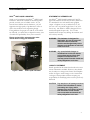
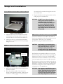
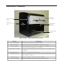
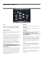
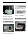
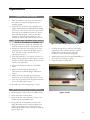
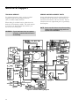
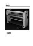
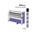
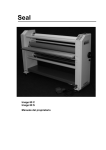
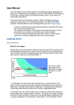
SEALTM
18XE
.
Owner’s
Operation
Manual
Important:
Read and understand all safety information before operating.
SEALTM 18XE
Liquid Coater
Table of Contents
TABLE OF CONTENTS......................................................................................................................... 2
INTRODUCTION.................................................................................................................................... 3
IMPORTANT SAFEGUARDS ................................................................................................................ 4
SET-UP AND INSTALLATION .............................................................................................................. 5
UNPACKING THE LAMINATOR ............................................................................................................................. 5
ROLLER INSTALLATION............................................................................................................................................ 5
PRINT CATCH TRAY INSTALLATION .................................................................................................................. 6
NEBULIZER INSTALLATION ................................................................................................................................... 6
ELECTRICAL REQUIREMENTS ............................................................................................................................... 6
LAMINATOR FEATURES...................................................................................................................... 7
FRONT CONTROL PANEL ......................................................................................................................................... 8
REAR CONTROL PANEL............................................................................................................................................. 9
LACQUER CONTAINER ............................................................................................................................................ 10
HUMIDIFIER SYSTEM................................................................................................................................................ 11
PRINT CATCH TRAY................................................................................................................................................... 11
SHUTTER CONTROL LEVER .................................................................................................................................. 12
BELT AND DRYER ASSEMBLIES........................................................................................................................... 12
DRAIN VALVE AND PLUG ...................................................................................................................................... 12
MATERIALS AND SUBSTRATES....................................................................................................... 13
OPERATIONS ..................................................................................................................................... 14
MEASURING VISCOSITY .......................................................................................................................................... 14
START-UP PROCEDURE............................................................................................................................................ 15
ROLLER HEIGHT ADJUSTMENT .......................................................................................................................... 15
SCRAPER ADJUSTMENT ........................................................................................................................................... 16
TEST PROCEDURE...................................................................................................................................................... 16
PROCESSING IMAGES ............................................................................................................................................... 17
CARE AND MAINTENANCE ............................................................................................................... 18
CLEANING THE LACQUER CONTAINER......................................................................................................... 18
CLEANING THE HUMIDIFIER............................................................................................................................... 18
LUBRICATION............................................................................................................................................................... 18
TROUBLESHOOTING GUIDE............................................................................................................. 19
SERVICE & SUPPORT........................................................................................................................ 20
TECHNICAL SPECIFICATIONS.......................................................................................................... 21
SPARE PARTS LIST ........................................................................................................................... 22
LIMITED WARRANTY ......................................................................................................................... 23
2
Introduction
SEAL
TM
18XE LIQUID LAMINATOR
SEALTM
Thank you for purchasing the
18XE Liquid
Laminator. The SEALTM 18XE has been designed to
provide you with years of reliable service. As you
become more familiar with the laminator, you will
appreciate the high quality of production it offers as
well as the excellence in its engineering design.
If the guidelines for proper care and use of the 18XE
are followed, you will be able to depend on many years
of trouble-free profitability from your investment.
Please read and fully understand the entire
manual before using your laminator.
STATEMENT OF INTENDED USE
The SEALTM 18XE Liquid Laminator is ETL/UL
approved and meets all relevant CE Safety Directives.
It is intended for use with small format graphics
output. Graphics can vary in widths from 4”-18”
(10.2 cm -45.7 cm) and in length from 6”-24” (15.2
cm-61 cm). The SEALTM 18XE is designed for use
with Seal Graphics lacquer only. Use of other
manufacturers’ lacquer may damage the machine and
will void any warranty.
WARNING: This laminator is designed for
laminating. Any use for purposes
other than that for which the
machine was designed may cause
damage to the laminator or physical
harm to the user.
WARNING: Any unauthorized changes or
modifications to this unit without
prior written approval from Seal
Graphics will void the user’s
warranty and will transfer health and
safety obligations to the user.
LIABILITY STATEMENT
Figure 1: SEAL
TM
18XE Liquid Laminator
Details provided in this manual are based on the most
current information available. However, these details
may be subject to change in the future. Seal Graphics
retains the right to make changes to the construction
or design of their products without accepting any
responsibility for modifying earlier versions previously
delivered.
CAUTION: Pay attention to all passages marked
in bold. This information is vital to
preventing user injury and/or
damage to the unit. Failure to follow
this information could void the
user’s warranties and transfer all
safety obligations to the user.
3
Important Safeguards
SAFETY INSTRUCTIONS
PREVENTIVE MEASURES
WARNING: Whenever using any equipment,
always follow manufacturers’
instructions to ensure safe operation.
Do not feed objects such as staples, paper clips and
rough or abrasive materials through the laminating
rollers.
Keep all objects, such as tools, rulers, pens, markers and
knives away from the roller opening. To prevent such
items from accidentally being fed into the rollers, do not
leave them on the laminator.
CAUTION: Read and make sure you understand
these safety and operating guidelines.
1. Do not operate the machine until it is connected to
a compatible power source.
2. Familiarize yourself with the layout of the control
panels and with the operation of the lacquer system.
3. Operators should be trained on the proper use of
the machine and all safety procedures.
4. Comply with all safety warning signs, labels and
instructions.
5. Ensure that eye protection and clean towels are
available for use during cleanup.
6. It is advisable to wear eye protection when
filling/emptying the lacquer container. Ensure that
an approved emergency eyewash station is adjacent
to the laminator.
CAUTION: Prior to handling any chemical
products, read the manufacturers’
product label and the Material Safety
Data Sheets (MSDS) for important
health, safety and environmental
information. Always observe
manufacturers recommendations
when handling chemicals.
To obtain MSDS Sheets for any Seal Graphics products,
contact Seal Graphics Technical Services at (410) 3795688 or (800) 490-4232.
4
SAFETY SYMBOLS USED ON THE LAMINATOR
ROTATING PARTS: RISK OF INJURY
WARNING: Failure to use caution near rotating
rollers could result in physical injury.
Be careful that items such as loose
clothing, long hair and jewelry do not
become entangled in rotating parts.
ELECTRICAL PARTS:
DANGER OF BEING INJURED
BY ELECTRICITY
DANGER!
ATTEMPT TO ACCESS THIS AREA
COULD RESULT IN PHYSICAL
INJURY BY HIGH VOLTAGE.
ONLY AUTHORIZED MAINTENANCE
OR SERVICE TECHNICIANS SHOULD
ATTEMPT REPAIR OF THIS AREA.
Setup and Installation
U N PA C K I N G T H E LA M I NA TO R
Remove the cardboard box and foam. Place the unit
in a well-lit, dust-free area where the floor of the work
area is level. The laminator should not be located near
open flames or high heat, such as heat registers, stoves
or ovens. The location of the laminator should not
interfere with proper ventilation.
RO L L E R I N S TA L L A T I O N
1. Facing the front of the machine, open the lacquer
container and remove the bag containing 2 bushings.
2. Remove the scraper bar by removing the two
thumbscrews that attach it to the roller assembly (see
Fig. 2).
Roller Bracket
Thumbscrews
Scraper Bar
Thumbscrews
Figure 2: Scraper Bar and Roller Brackets
3. Remove the roller bracket thumbscrews and open
the roller brackets (see Fig 2 and Fig 3).
4. Take one of the silicone rubber rollers and slide a
bushing onto each of its rods. Next, place this silicone
rubber roller in the roller brackets with the long end of
the roller containing the plastic gear pointing to the
right.
Figure 3: Roller Assembly with Roller
Brackets Open
5. Slide a bushing onto the other silicone rubber roller.
Place this silicone rubber roller on top of the other
silicone rubber roller that is already in the roller
brackets. Be sure that the plastic gears are lined up on
the right side.
6. The top metal roller goes in last. Slide the
aluminum gear into the motor belt on the left and then
place the top metal roller on top of the middle silicone
rubber roller. The plastic gears on the top, middle and
bottom rollers should align with each other on the
right hand side.
7. Close the roller brackets and screw in the two
thumbscrews until they are snug. Do not over tighten
or the threads may become stripped.
8. Attach the scraper bar with the remaining two
thumbscrews and tighten until they are snug.
9. Close the lacquer container.
NOTE: Make sure that the bushings are tight
against roller cores and that the bushing
shoulder is sitting inside of the roller
brackets
5
Setup and Installation
P R I N T C A TC H T R AY I N S TA L L A T I O N
the outside of the container through the notch in
the container side.
3. Plug the nebulizer into the open connector of the
cable going to the nebulizer fan.
WARNING: DO NOT plug in the unit without
making sure that the nebulizer is
standing upright and that the
humidifier container is filled with 2
in. (5 cm) of DISTILLED WATER.
Running the nebulizer not in the
upright position and without water
may damage the unit and will void
the warranty.
Figure 4: Print Catch Tray
1. The print catch tray can be installed on the back
of the machine by lowering the slots on the tray
onto the frame of the rear side of the lamina tor.
2. The length of the tray can be adjusted anywhere
from 18 in. to 25 in. (46 cm to 63.5 cm) by simply
sliding it in or out.
N E BU L I Z E R I N S TAL L A T I O N
Nebulizer
Electrical
Connection
ELECTRICAL REQUIREMENTS
Connect the laminator in accordance with details as
listed on the identification label located below the rear
control panel. Refer also to the “Technical
Specifications” page for additional information.
CAUTION: Seal Graphics recommends that a
licensed electrician, in accordance
with electrical codes in your area,
install your main power or the
warranty will be void. Specifications
are subject to change without notice.
Figure 5: Inside of Nebulizer Container
Seal Graphics recommends installation of a Ground
Fault Interrupter (GFI) circuit breaker if operating the
laminator near water or in an area of high humidity.
The laminator must be installed close to the electrical
outlet. The plug and outlet must be readily accessible.
Plug the power cord into the grounded outlet with the
appropriate electrical service for your area. Ensure that
the outlet to be used is a three prong grounded outlet,
and that the configuration of the outlet matches the
configuration of the supplied plug.
1. Remove the nebulizer from its box located in the
nebulizer container.
2. Place the nebulizer inside of the circle in the
bottom of the nebulizer container. Make sure the
nebulizer is standing upright. Route the cable to
WARNING: Any changes or modifications to the
unit supplied, without the express
written authorization and consent of
Seal Graphics will void the user’s
warranty, and will transfer all health
and safety obligations to the user.
6
Laminator Features
Lacquer
Container
Shutter Control
Lever
Print Catch
Tray
Drain Valve
and Plug
Front Control
Panel
Figure 6: SEAL
TM
18XE Liquid Laminator Features
Feature
Description
Front Control Panel
Rear Control Panel
Lacquer Container
Controls the motor, fans, heaters and humidifier.
Contains the power switch and laminator fuse (refer to figure 8).
Container in which the top metal roller, middle silicone rubber roller, bottom
silicone rubber roller and lacquer are contained.
An array of 9 fans and 3 heaters used to dry lacquer on coated images (refer
to figure 15).
Lever used to open and close the shutter.
Consists of a nebulizer, a nebulizer container and a water distribution system
(refer to figures 11 and 12).
Belt and Dryer Assembly
Shutter Control Lever
Humidifier System
Print Catch Tray
Drain Valve and Plug
Used to retain images as they exit the dryer assembly.
Used to drain lacquer and wash water at the end of operations.
7
Laminator Features
F RO N T C O N T RO L PA N E L
Figure 7: Front Control Panel
LOW
RUN Mode
When lit, this Light Emitting Diode (LED) indicates
that the amount of distilled water in the humidifier
bottle is running low and needs to be replenished.
In RUN Mode, the motor, fans and heaters are ON.
HUMIDITY VOLUME
STOP Mode
The position of this setting knob controls the amount
of time the humidifier is ON during a 60-second
period.
During the STOP and IDLE Modes, the humidifier
runs for the number of seconds that the knob is set to.
For example, if the humidity volume setting is set on
10, the humidifier will run for 10 seconds and cycle off
for 50 seconds to complete the 60-second cycle.
During the RUN Mode, humidifier runs for 2 times
the number the knob is on. For example, if the
humidity volume setting is set on 10, the humidifier
will run for 20 seconds and cycle off for 40 seconds to
complete the 60-second cycle.
In STOP Mode, the motor, heaters and fans are OFF.
NOTE: When the humidifier is in operation, the
humidity volume LED will be lit.
RUN/IDLE/STOP
When pressed, the selected mode is enabled, and the
previously set mode is disabled. These touch switches
are used to select the mode of transport powered by
the feed motor. The three selectable modes are the
RUN, IDLE, and STOP Modes. A lit LED in the two
o’clock position from the mode selection switch
indicates the selected mode.
8
IDLE Mode
In IDLE Mode the motor is ON, while the heaters
and fan are both OFF.
NOTE: The humidifier operates in all three
modes.
ROTATE SHUTTER
The shutter is located at the exit point of the lacquer
container. The purpose of the shutter is to maintain
the humidity level within the lacquer container. When
blinking, the rotate shutter LED indicates that the
shutter is not in the correct position and needs to be
manually rotated (see the “Shutter Control Lever”
section).
Normally, whenever the laminator is in either STOP
or IDLE modes, the shutter should be closed.
Whenever the laminator is set to RUN mode, the
shutter must be open.
If the shutter is open when in STOP or IDLE Mode,
the LED will blink to indicate the shutter needs to be
closed.
If the shutter is closed and then the RUN mode is
selected, the machine will not be allowed to enter
RUN mode.
Laminator Features
If during RUN mode the shutter is rotated from the
open to the closed position, the LED will blink
indicating the shutter needs to be opened. If the
shutter is not opened within 2 seconds, the machine
will automatically switch from RUN mode to IDLE
mode, and the LED will go out.
NOTE: Remember to close the shutter if the
laminator is set to IDLE and will not be
used within 5 minutes.
SPEED (Motor Speed Adjustment Knob)
The motor speed can be adjusted in a range from 0 to
15 fpm (0 to 4.6 mpm).
Turning the knob clockwise will cause the speed of the
motor to increase.
Turning the knob counterclockwise will cause the
speed of the motor to decrease.
F/R (Forward/Reverse)
The selected Motor Direction Touch Switch controls
the direction of the feed motor, forward (F) and
reverse (R). The LED adjacent to the selector touch
switch indicates the selected direction.
When FORWARD is selected, the feed motor feeds
images through the laminator from front to back.
This direction should be used during normal
laminating operations.
The REVERSE position should only be used to
retrieve jammed images.
R E A R C O N T RO L PA N E L
Power On/Off Switch
Fuse
Power AC Inlet
Figure 8: Rear Control Panel
FUSE
POWER AC INLET
2.5A main power fuse for the laminator.
The power supply cord connects to the Power AC
Inlet.
I/O (Power On/Off Switch)
Controls the laminator main power setting, ON or
OFF.
9
Laminator Features
L A C Q U E R C O N TA IN E R
on the top left and right hand side of the lacquer
container. See the section on “Roller Height
Adjustment.”
The purpose of the drain valve, located on the bottom
of the lacquer container, is to empty lacquer and wash
water from the container at the end of operations. See
the section on “Cleaning the Lacquer Container.”
Roller Height
Adjustment Screws
(2)
Lacquer Container
Door
Figure 9: Lacquer Container
Scraper Bar
The lacquer container consists of the top metal roller,
middle silicone rubber roller, bottom silicone rubber
roller, scraper bar and lacquer.
The top and middle rollers are geared and powered by
the laminator’s motor. They are used to grasp the
image being fed into the laminator.
The middle silicone rubber roller applies pressure on
the bottom silicone rubber roller, causing it to rotate
in the lacquer. The bottom silicone rubber roller picks
up the lacquer and transfers it to the middle silicone
rubber roller, which in turn applies the lacquer to the
media. If there is no media present, the middle
silicone rubber roller transfers the lacquer to the top
metal roller. The scraper then scrapes the lacquer
from the top metal roller and transfers it back to the
lacquer container.
The humidity inside the lacquer container is controlled
by the humidity volume adjustment knob, which is
used to maintain the correct viscosity of the lacquer.
See the “Processing Images” section.
Because of the controlled environment, the laminator
can be operated for one week without having to stop
and clean the lacquer container.
The space between the top metal roller and the middle
silicone rubber roller needs to be adjusted to ensure
that the media is receiving the correct amount of
lacquer. This space is called the nip. It is adjusted by
raising or lowering the bottom and middle rollers
using the two roller height adjustment screws located
10
Top Metal Roller
Nip
Middle Silicone
Rubber Roller
Bottom Silicone
Rubber Roller
Drain Valve
Figure 10: Section View of the Lacquer
Laminator Features
H U M I D I F I E R S Y S TE M
humidifier container is filled with 2
in. (5 cm) of DISTILLED WATER.
Running the nebulizer not in the
upright position and without water
may damage the unit and will void
the warranty.
The humidifier system has a water supply bottle,
which MUST be checked daily and filled as required
with DISTILLED WATER.
NOTE: The humidifier bottle must be placed at a
higher elevation than that of the
nebulizer container. This ensures that
the water will drain from the bottle and
into the nebulizer container.
Figure 11: Nebulizer Container
The humidifier system consists of a nebulizer, a
nebulizer container and a water distribution system.
The water distribution system delivers moisture
droplets to the lacquer container.
The nebulizer has either an internal float or a water
level probe, which does not allow the humidifier to
operate without water. If the nebulizer is not in the
upright position, the float or probe may not work and
the nebulizer may become damaged when the
humidifier container runs out of water.
NOTE: Once a week place a few drops of white
vinegar on the transducer disk and
polish it off with a Q-tip. This will help
ensure long life of the nebulizer.
There is a humidity volume adjustment knob on the
front control panel used to adjust the rate at which
water droplets are delivered to the lacquer container.
See the section on humidity volume under “Front
Control Panel.” Whenever the humidifier is in
operation, the humidity volume LED on the front
control panel will be illuminated.
NOTE: Make sure that the hose running from the
nebulizer container to the lacquer
container remains at an incline so that
water does not collect in the hose.
P R I N T C A TC H T R AY
Transducer Disk
Figure 13: Print Catch Tray
Figure 12: Nebulizer
WARNING: DO NOT plug in the unit without
making sure that the nebulizer is
standing upright and that the
The print catch tray, mounted on the rear of the
laminator, is designed to retain images as they leave
the dryer assembly.
11
Laminator Features
S H U T T E R CO N T RO L L E V E R
BELT ASSEMBLY
The self-contained belt assembly provides movement
of the coated images over the air dryer system. The
speed at which the images move is controlled using
the speed switch on the front control panel.
AIR DRYER SYSTEM
The air dryer system is an array of nine fans (120 cfm
each) and three heaters (400-Watt each) that are
designed to dry the coated media by blowing warm air
across the belt as images are fed through the
laminator.
D R A I N VA LV E A N D P L U G
Figure 14: Manual Shutter Control Lever
The purpose of the shutter is to maintain the level of
humidity within the lacquer container by isolating it
from the air dryer system. By doing so, the correct
viscosity of the lacquer is maintained, which means
that the lacquer may be used for a longer period of
time.
CAUTION: Never feed images into the machine
when the shutter is closed. Always
open the shutter before feeding
images, or the shutter will prevent
the image from being fed into the
drying system and the machine may
become jammed.
B E LT A N D D RY E R A S S E M B L I E S
Drain Valve
Plug
Figure 16: Drain Valve and Plug
The purpose of the drain plug is to ensure that no
lacquer leaks out of the lacquer container and to
prevent any air from seeping into the valve and drying
lacquer around the valve. After removing the drain
plug, the drain valve can be opened to return the
lacquer back to its original bottle.
NOTE: Whenever lacquer is in the lacquer
container the drain valve should be in the
closed position and the plug in place,
except when draining lacquer from the
lacquer container.
Figure 15: Belt and Dryer Assemblies
12
Materials and Substrates
MATERIAL SIZES
Almost any pliable substrate up to 18 in. (45.7 cm) in
width can be coated using the SEALTM 18XE
Laminator. Exceptions are thin, porous materials such
as newspaper and some pretreated surfaces.
MATERIALS THAT CAN BE COATED
1. All photographic papers.
2. Most substrates used for digital imaging.
NOTE: Always make a test coat using a sample
of the material to be coated with the
TM
SEAL 18XE laminator prior to
production.
ADDITIONAL COATS
1. Adding additional coats by sending an image
through the laminator several times will:
•
Increase moisture resistance.
• Give images a different, more textured look.
2. An image that has previously been coated with one
type of lacquer can be recoated with a different type
of lacquer.
3. An image previously coated can be spot cleaned
using a Q-tip soaked in alcohol, and may be coated
again. (This may require several passes.)
CAUTION: Some small size images may fall off
the belt inside the air dryer. To help
prevent this from happening, feed
small size images into the center of
the in-feed slot. If images do fall,
they can be retrieved through the
rear opening of the dryer after the
main power is turned OFF.
CAUTION: Small images should be fed into the
machine leading with the corner
versus the edge, so that they don’t
hang-up.
13
Operations
MEASURING VISCOSITY
Prior to operations, check the viscosity or thickness of
the lacquer to be used. To measure the viscosity of
the lacquer, you will need a #2-Zahn Viscosity Cup
and a stopwatch. The cup has a hole in the bottom
from which the lacquer will run out until the cup is
empty.
The amount of time that it takes to empty the cup
(Zahn-seconds) is used to calculate the viscosity or
thickness of the fluid tested. The thicker the fluid, the
longer it will take to empty the cup.
NOTE: Water measures at a rate of 14 Zahnseconds.
The lacquer being used for coating should drain in the
35 to 50 Zahn-second range.
To measure the viscosity of the lacquer you are using
in your laminator, you will need the following:
1. One 16-ounce cup of lacquer. (If necessary, filter
the lacquer to ensure that there are no particles
present which may otherwise block the drain hole
in the Zahn Cup.)
2. A #2 Zahn Viscosity Cup
3. A stopwatch
Figure 17: #2 Zahn Viscosity Cup
14
MEASUREMENT PROCEDURE
1. Immerse the #2 Zahn Cup fully in the lacquer.
2. Raise the cup out of the lacquer. Immediately as
the top edge of the #2 Zahn Cup emerges from
the lacquer, start the stopwatch.
3. The stream of lacquer draining from the hole in
the bottom of the #2 Zahn Cup will get thinner
and thinner as the cup empties, until a point
where the continuous flow is broken.
4. Watch for the break in flow about 10 in. (25 cm)
below the bottom of the cup.
5. When the stream breaks its continuous flow, stop
the stopwatch.
NOTE: Flow will most likely resume again
following the initial break in continuous
flow. Ignore any additional flow.
6. Repeat the measurement a second time to verify
the accuracy of the measurement. Values from
both measurements should be identical.
7. If the lacquer is in the 35-50 Zahn second range, it
is good to use. Thick lacquer can be restored to
normal by adding distilled water.
NOTE: Particles in the lacquer may plug the hole
in the cup, breaking the stream giving
you an inaccurate time. Verify that no
particles have plugged the hole.
Operations
S TA RT- U P P RO C E D U R E
1. Place the nebulizer in the ring in the bottom of
the nebulizer container; making sure that it is
standing upright.
2. Check the level of water in the humidifier water
supply bottle and fill with DISTILLED WATER
if necessary. Place the water bottle at an elevation
above that of the nebulizer container so that the
water will drain properly. Allow the nebulizer
container to fill to the float switch level. The
nebulizer should be fully submerged in the water.
NOTE: Distilled water should be used to prolong
the life of the nebulizer (humidifier) unit.
3. Using the drain valve, empty any water that may
be in the lacquer container. Close the drain valve.
4. Measure the viscosity of the lacquer to be used
and make sure it’s within the allowable range of
35 to 50 Zahn-seconds. See the section on
“Measuring Viscosity.”
5. Pour approximately 2/3 of a gallon (2.5 liters) of
lacquer coating solution into the lacquer container.
(Lacquer should be about half way up the bottom
transfer roller when full.)
6. Turn on the laminator and set it to the IDLE
mode.
7. Adjust the roller height by following the
instructions in the “Roller Height Adjustment”
section.
8. Adjust the scraper assembly by following the
instructions in the “Scraper Adjustment” section.
9. Coat some test prints by following the instructions
in the “Test Procedure” section.
10. Proceed to the “Processing Images” section.
Figure 18: Roller Height Adjustment Screws
1. Looking through the nip, turn the roller height
adjustment screws clockwise until the top and
middle rollers just barely touch. The light
between the rollers should just disappear.
2. Additional pressure may be required depending on
the results from running test prints.
3. Close the lacquer container door.
Nip
RO L L E R H E I G H T A D J U S T M EN T
1. Set the transport mode switch to the IDLE mode.
2. Open the lacquer container door.
3. Open the shutter. This will make it easier to see
between the top and middle rollers.
4. Facing the front of the machine, turn the roller
height adjustment screws counterclockwise until
you see a gap between the top metal roller and
middle silicone rubber roller. This gap is called the
nip (see figure 19).
Figure 19: Nip
15
Operations
S C R A P E R A D J U S T ME N T
Figure 20: Scraper Bar and M4
Adjustment Screws
NOTE: The scraper adjustment must be done
with lacquer in the lacquer container.
1. Set the transport mode switch to the STOP mode.
2. Open the lacquer container door.
3. Remove the scraper bar by removing the two
thumbscrews that are holding it in place.
4. Two M4 Hex head screws are located just above
the thumbscrews that attach the scraper assembly
to the lacquer container. They are used to adjust
the scraper pressure against the top nip roller.
Extending the screws will drive the scraper bar
down and in turn will exert more force on the
scraper blade.
5. Start with the two M4 Hex head screws screwed
all the way in. Attach the scraper bar to the
lacquer container using the two thumbscrews.
6. Run test prints by following the instructions in the
“Test Procedure” section. Check the prints. If
they are not to satisfaction, extend the two M4
screws slightly and run the test procedure again.
Continue this process until the prints meet your
satisfaction. You may then proceed to the
“Processing Images” section.
NOTE: The best set point for the scraper bar is a
clean print back with the least amount of
scraper pressure.
NOTE: Be aware that faint small streaks on the
back of the print may be due to nicks or
cuts in the edge of the scraper and won’t
disappear with more scraper pressure.
16
T E S T P RO C ED U R E
1. Set the transport mode to RUN.
2. Turn the motor speed adjustment knob to “10.”
Check the crack between the top metal roller and
middle silicone rubber roller for excess lacquer.
Allow a couple of minutes of run time for excess
lacquer to disappear. Excess lacquer between the
rollers will be picked up by the material and will
coat both sides of the leading edge of the material.
If excess lacquer does not disappear:
a) Check the scraper. It may not be scraping
properly.
b) Check the roller adjustment. Rollers may be
adjusted too loose. Turn the roller height
adjustment screws 1/4 turn clockwise and
wait two minutes for excess lacquer to
disappear.
NOTE: Feed images into the machine face down.
3. Turn the motor speed knob to “5.” Set the
transport mode to RUN and coat several 18 x 24
prints and check the following:
a) The prints should be “dry” exiting the
machine. They may feel damp but the lacquer
should not be wet (come off on your fingers),
and stacked prints should not stick to each
other. If the prints are not “dry” enough,
slow the speed of the machine to extend the
drying time.
b) Check the coating on the test prints for
recurring marks. If the coating roller has a
defect, the mark will repeat every 4.5” (11.4
cm), the circumference of the roller. Check
the coatings for evenness of application. The
whole surface should be uniformly coated;
there should be no bare spots and no thick or
oddly textured areas.
c) Check the backs of the prints. They should
be clean with no lacquer streaking. If they are
not clean, increase the scraper pressure.
NOTE: Whenever running machine in Idle Mode for
extended periods, dust may collect. Be sure to
allow machine to operate in RUN Mode for a few
minutes prior to processing images so that the fans
can purge any dust/debris that may have collected.
Operations
P RO C E S S IN G I M A GE S
The unit can be run for several days without draining
the lacquer. To accomplish this, a balance must be
found between the humidifier and the actual drying
rate of your location. (This can vary due to
environmental conditions).
If the humidifier is set too high, the lacquer will
absorb the water and become less viscous, meaning
that there is too much water and the lacquer will
become too thin and unusable.
If the humidifier is set too low, the lacquer will thicken
and build up on the scraper.
1. Complete the start-up and test procedures.
2. Set the transport mode switch to IDLE.
3. Adjust the motor speed based on the test
procedure. The motor speed controls the amount
of time that the image remains in the dryer.
If MORE drying time is needed (due to a high
ambient humidity), DECREASE the motor speed.
If LESS drying time is needed, INCREASE the
motor speed.
4. The humidity volume control knob controls the
humidifier. Humidity is adjustable in a range of 1
to 10 with a setting of 10 producing the highest
amount of mist. Start with a setting of 2.
5. Open the shutter and set the transport mode
switch to RUN.
6. Feed images into the laminator face down.
CAUTION: Adjust the roller height and scraper
tension before processing images.
7. When finished, set the transport mode switch to
IDLE and then close the shutter.
8. At the end of the day measure the lacquer
viscosity again. It should be within one or two
seconds of the viscosity measurement at the
beginning of the day and still within the 35 to 50
second range. Note the date and the measured
viscosity in a logbook kept near the laminator.
9. If the lacquer is too thin (has lower viscosity),
reduce the humidifier setting.
10. If the lacquer is too thick (has higher viscosity),
increase the humidifier setting.
NOTE: Thick lacquer can be restored to normal
by adding distilled water.
11. Be aware that humidity settings can vary over the
course of the year—dryer with the winter heating
systems turned on, moister in the summer during
humid conditions. You may need to adjust for
seasonal changes.
NOTE: The machine should be left in the IDLE
mode whenever left on overnight.
Remember to close the shutter and fill
the water supply bottle. The humidifier
will maintain the condition of the roller
assembly overnight. The next day,
always confirm that lacquer has not dried
around the roller bushings and that the
rollers are still adjustable with the Height
Adjustment Screws.
12. The laminator should be drained and thoroughly
cleaned once a week as described in the “Cleaning
the Lacquer Container” section.
17
Care and Maintenance
WEEKLY MAINTENANCE
Both the lacquer container and the humidifier
container require a thorough weekly cleaning. The
lacquer container needs to be maintained to ensure
minimal lacquer buildup. The humidifier container
must be kept clean to avoid contamination from
bacteria or mold.
C L E A N I N G TH E L A C Q U E R
C O N TA I N E R
1. Be sure that the machine is in STOP mode and
that the shutter is closed.
2. Set the motor speed knob to “10.”
3. Place an empty lacquer bottle under the drain
valve. Remove the drain plug, open the valve and
drain the lacquer.
4. The lacquer container is sloped towards the drain
valve. A paintbrush (supplied) may be used to
push the remaining lacquer towards the drain.
5. Close the valve and pour approximately one gallon
(3.8 liters) of water into the lacquer container.
NOTE: Fill the lacquer container with water
immediately after draining the lacquer.
Water-based lacquer will dry within three
to four minutes.
6. Run the laminator for two minutes in IDLE mode
and then set the transport mode to STOP.
7. Remove the thumbscrews and lower the scraper
bar into the water. Using a paintbrush, clean the
scraper.
8. Place an empty lacquer bottle under the drain
valve and drain the wash water.
9. Close the valve and pour one gallon (3.8 liters) of
cleaning solution into the lacquer container. The
cleaning solution is 3 parts water, one part alcohol
and one part household detergent (i.e. Simple
Green, 409, etc.).
10. Rinse the scraper in the cleaning solution and then
reinstall the scraper.
18
11. Run the machine in IDLE for an additional 15-20
minutes while you clean the humidifier container.
12. If there is no buildup of lacquer, drain the
cleaning solution and rinse parts clean.
13. If lacquer is built up, it may be necessary to leave
the solution in the container over the weekend.
NOTE: Rollers and bushings may be thoroughly
cleaned by removing them from the
machine.
14. After running the machine in IDLE for the 15-20
minute period, loosen the roller adjusting knobs
on top of the lacquer container to release the
pressure between the nip rollers.
15. Rinse the lacquer container, rollers and scraper
bar with clean water.
16. Rinse a second time.
17. To complete operations, press the STOP touch
switch.
C L E A N I N G TH E H U M I D I F I E R
1. Remove the nebulizer container from the
machine, drain the water and clean with a mild
cleaner.
2. Allow the container to thoroughly air dry.
3. Place a few drops of white vinegar on the
nebulizer’s transducer disk and polish it off with a
Q-tip (refer to figure 12).
LUBRICATION
Feed Motor: The motor is sealed and prelubricated and requires no maintenance.
Fans: The fans are also sealed and prelubricated and require no maintenance.
Dryer System: The heaters and air dryer belt
require no maintenance.
Gears: Generally speaking, the plastic gears
used to rotate the top and middle rollers do not
require lubrication. However, should the gears
develop a “squeak,” a drop of household oil
should eliminate the problem.
Troubleshooting Guide
POSSIBLE CAUSE
SOLUTION
Pressure not released from rollers after machine was shut
down. The roller has an indentation where the two
rollers stayed in contact with one another.
Run machine for one or two hours with the pressure
on.
PROBLEM
Coating is uneven
-orHorizontal lines are visible on
output.
Coating is uneven
-orVertical lines are visible on
output.
Random spots or marks on
output.
Lacquer appears on back of
image.
Horizontal lines may occur for the same reason.
Clean rollers with straight alcohol.
If horizontal lines persist, roller may have been
permanently damaged.
Replace roller.
Rollers are not clean.
Lacquer level is too low.
Lacquer is deteriorating (due to old age or because it has
been diluted with water).
Lacquer is too thick.
Clean rollers.
Add lacquer to the correct level.
Replace old lacquer.
Lacquer is too thin
Run coating in machine with humidity dial on “0” until
coating reaches desired thickness (35-55 seconds).
Dirt or dried lacquer may be stuck to the rollers. Lacquer
may have dirt in it.
Clean rollers with straight alcohol.
Restore lacquer to normal viscosity by adding a mixture
of alcohol (20%) and water (80%).
Filter lacquer with paint strainer or fine wire filter.
Scraper tension is not enough.
Increase scraper tension (adjust scraper tension screws).
Scraper blade may be worn or have nicks.
Remove and replace scraper blade.
Scraper blade may have lacquer built up on blade.
Clean blade with alcohol.
Fans not running or defective.
Inspect fan operation and if faulty, call Technical
Service.
Shutter is not open.
Open shutter, and if necessary remove jammed images
by running unit in reverse.
(Run) speed is too slow.
Increase speed.
Coating is too thin.
Run coating in machine with humidity dial on “0” until
desired viscosity is reached (35-55 sec).
Set screws in gears may have come loose.
Tighten set screws making sure one set screw is on flat
side of shaft.
Not enough scraper blade tension.
Increase scraper blade tension (adjust scraper blade
screws-see page 16)
Run speed is too slow.
Increase speed.
No power.
Verify that power cable is not loose.
Power switch fails to set.
Verify that the main power switch is in the “ON”
position.
Dried lacquer accumulating on roller brackets.
Clean unit. Remove and clean rollers and roller
bushings thoroughly. Inspect and clean roller brackets,
insuring there is no lacquer build-up.
Set screws in gears have come loose or backed out.
Tighten set screws making sure one set is on flat side of
shaft.
Motor will not run.
Blown fuse.
Check the 2.5A fuse and replace if blown.
Knocking sound or roller
hesitation.
Loose belt tension.
Remove top cover and check belt tension (should not
have any slack) Tighten is needed.
Low level light staying on.
Bad connection from power source.
Ensure connection is made to nebulizer and fan.
Low water level.
Ensure 1 gallon jug is full with distilled water.
Float directly on nebulizer may be stuck.
Free float in nebulizer to allow float to move freely up
and down.
Prints not exiting machine.
Prints sticking to rubber
coating roller (common with
inkjet paper).
Prints wrapping around top
steel roller.
Laminator does not turn on.
Silicone roller(s) not turning.
19
Service & Support
TECHNICAL SERVICE
SERVICE AND REPLACEMENT PARTS
For technical assistance, please contact your Seal
Graphics technical service representative at:
(410) 379-5688 or (888) 490-4232.
When calling for technical service, please have the
laminator serial number available. The serial number
is located on the identification label, which is just
below the rear control panel.
Service and maintenance must be performed fully in
accordance with the instructions. Servicing by any
unauthorized technician voids the warranty. Service
technician must use replacement parts as specified by
Seal Graphics.
WARNING: If your laminator does not operate
correctly, contact technical service
immediately.
NOTE: Service technicians must perform safety
checks after completing any service or
repairs to the laminator.
Figure 21: Electrical Wiring Diagram
20
Technical Specifications
Mechanical
Dimensions (H x W x D)
Shipping Dimensions
Net Weight
Shipping Weight
26 in. h x 28 in. w x 23 in. d (66 cm x 71 cm x 58 cm)
Note: With catch tray installed, width (w) = 43 in. (110 cm)
32 in. x 32 in. x 32 in. (82 cm x 82 cm x 82 cm)
120 lbs. (54.4 kg)
162 lbs. (73.5 kg)
Process
Max. Media Size
Variable Coating Speed
18 in. x 24 in. (45.7 cm x 61 cm)
5 to 15 fpm (1.5 to 4.6 mpm)
Electrical
Single Phase
Environment
Temperature
Relative Humidity
Moisture
Cleanliness
115 VAC 50/60 Hz, 12A
230 VAC 50/60 Hz, 6A
50°F to 86°F (10°C to 30°C)
30% to 79% Relative Humidity
Dry Moisture Free Environment
Dirt free, clean environment
Each Seal Graphics laminator has an identification label located below the rear control panel. This label
indicates the model type, the electrical requirements and the laminator serial number (important for reference if
servicing is required).
21
Spare Parts List
88160511……………… BOTTLE WITH FITTING & TUBING
88160512……………… MOTOR WITH BRACKET AND PULLEY
88160513……………… CONTROL BOARD ASSEMBLY
88160514……………… NEBULIZER
88160516………………NEBULIZER – REPLACEMENT DISK ONLY
88175500……………… COLLECTOR TRAY ASSEMBLY
88175501……………… THUMB SCREW ¼-20 - ROLLER ADJUSTMENT
88160522……………… NEBULIZER CONTAINER & FLOAT
88175503……………… ROLLER BRACKET WITH LIFTER BRACKET RH
88175504……………… ROLLER BRACKET WITH LIFTER BRACKET LH
88175505……………… HEATER
88210510……………… ROLLER TOP - STAINLESS STEEL
88210511……………… ROLLER - RUBBER
88210522……………… STIFFENER SCRAPER BLADE - STAINLESS STEEL
88300520……………… SCRAPER BLADE – PLASTIC
88160519……………… SCRAPER ASSEMBLY (blade, stiffener, bracket, and shield)
88300525……………… BUSHING - ROLLERS & TRANSPORT SHAFT
88300526……………… GEAR 52 TOOTH
88500542……………… THUMB SCREW M5 - ROLLERS & SCRAPER ASSEMBLY
88505510……………… BELT - PULLEY
88510510……………… PULLEY
88525501……………… TUBING ¼” - JUG (ORDER PER FOOT)
88525503……………… COUPLER - ¼” TUBING
88525515……………… DRAIN VALVE
88525520……………… PLUG - DRAIN VALVE
A530104………………. TUBING ½” - NEBULIZER
88700523……………… BOARD POWER/RELAY
88700552……………… FAN - TRANSPORT
88700553……………… FAN - NEBULIZER CONTAINER
88700556……………… SWITCH - MAIN POWER
88700557……………… TERMINAL BLOCK - HEATER LEADS
88700558……………… FUSE T-2.5AL 5 X 20mm
88700570……………… MICROSWITCH - SHUTTER
88705507……………… POWER CORD - 115V
88705513……………… POWER CORD – 230V
22
Warranty
The warranty period and conditions stated in this
chapter are merely a summary of the general Seal
warranty conditions. For the exact details on the
warranty period and conditions for your machine, please
contact your dealer.
The warranty ends when:
•
•
•
The periods stated above have expired.
The machine changes possession.
Warranty is voided by any of the
conditions mentioned above.
WARRANTY CONDITIONS
The manufacturer warrants to the original end user*
that the machine when proven defective in materials or
workmanship, within the applicable warranty period will
be repaired, or (at our option) replaced without charge.
Note:
The main rollers are subject to normal
wear and tear and therefore have warranty
on material defects only.
WARNING: Any unauthorized changes or
modifications to this unit without Seal
Graphics’s prior written approval will
void the user’s warranty and will
transfer health and safety obligations
to the user.
WARNING: Changes or modifications to this unit
not expressly approved by the party
responsible for compliance could void
the user's authority to operate the
equipment
The manufacturer or its representative shall not be liable
for any damage caused by the machine nor loss of
productivity.
Warranty is voided when:
• Changes or modifications are made to
this machine, not explicitly approved by
the manufacturer,
• The machine is changed or modified by
unauthorized persons,
• The machine is used under other than
normal working conditions,
• The machine is used for purposes other
than intended for (see page 3).
* The original end user is the person that first purchased
the machine from the manufacturer or its representative.
WARRANTY PERIOD
The standard warranty period on this machine is one
year from the date of purchase.
This period however can be longer due to local law or
purchase agreement.
The main rollers have a warranty period of 6 months on
material defects only.
23
Disclaimer
DISCLAIMER
All rights are reserved. No part of the document may be
photocopied, reproduced, or translated to another
language without the prior written consent of Seal
Graphics.
The information contained in this document is subject
to change without notice and should not be construed
as a commitment by Seal Graphics.
24
Seal Graphics assumes no responsibility for any errors
that may appear in this document. Nor does it make
expressed or implied warranty of any kind with regard
to this material, including, but not limited to, the implied
warranties of merchantability and fitness for a particular
purpose.
Seal Graphics shall not be liable for incidental or
consequential damages in connection with, or arising
out of the furnishing, performance, or use of this
document and the program material, which it describes.
Seal Graphics Technical Service
(For technical assistance & service)
Tel: (888) 490-4232
Fax: (410) 579-8959
Seal Graphics Customer Service
(For information and placing orders)
Tel: (888) 490-4232
Fax: (410) 579-8959
Note: Seal Graphics recommends that your main power be installed by a licensed electrician in
accordance with electrical codes in your area. Specifications are subject to change without notice.
Seal Graphics
U.K. Ltd
Unit 1, 1 Watkins Close
Burnt Mills Industrial Estate
Basildon, Essex SS13 1BJ
United Kingdom
Tel: +44 1268 722 400
Fax: +44 1268 729 442
Seal Graphics
Europe BV
Kanaaldijk, O.Z.3
P.O. Box 29,
8100 AA Raalte
The Netherlands
Tel: +31 572 345 500
Fax: +31 572 345 501
Seal Graphics
Pacific Limited
Unit A, 13th Floor, Block 1
Leader Industrial Centre
Tsuen Wan,
New Territories, Hong Kong
Tel: +852 2407 3738
Fax: +852 2408 0973
© 2007 Seal Graphics
Part #7001539 Rev. A
(08/28/07)
27