1
GB
BU 0000
NORD CON
Manual for NORD CON
NORD CON Manual
...................................................................................................................................... 10
1 Introduction
1.1 About NORD
.......................................................................................................................................10
CON
1.2 How to .......................................................................................................................................10
use NORD CON
......................................................................................................................................
13
2 Graphic user
interface
2.1 Structure
.......................................................................................................................................13
of the program interface
2.2 Main menu
.......................................................................................................................................14
2.2.1 Category
..............................................................................................................................................14
"File"
2.2.2 Category
..............................................................................................................................................16
"Edit"
2.2.3 Category
..............................................................................................................................................17
"Project"
2.2.4 Category
..............................................................................................................................................18
"Device"
2.2.5 Category
..............................................................................................................................................19
"View"
2.2.6 Category
..............................................................................................................................................20
"Extras"
2.2.7 Category
..............................................................................................................................................20
"Help"
2.3 Toolbars
.......................................................................................................................................22
2.3.1 Standard
..............................................................................................................................................22
2.3.2 Device
..............................................................................................................................................23
2.3.3 Start
..............................................................................................................................................24
2.4 View "Project"
.......................................................................................................................................24
2.4.1 Structure
..............................................................................................................................................25
of popup menu
2.5 View "Messages"
.......................................................................................................................................27
2.6 View "Remote"
.......................................................................................................................................27
2.7 Docking.......................................................................................................................................28
and Undocking
...................................................................................................................................... 34
3 Communication
3.1 Overview
.......................................................................................................................................34
3.2 USS
.......................................................................................................................................34
3.2.1 General
..............................................................................................................................................34
settings
3.2.2 Bus
..............................................................................................................................................35
scan
3.3 USS over
.......................................................................................................................................37
TCP
3.3.1 General
..............................................................................................................................................37
settings
3.3.2 TCP
..............................................................................................................................................38
...................................................................................................................................... 40
4 Parameterization
BU 0000 GB
© NORD DRIVESYSTEMS 2015
2
Table of Contents
4.1 Overview
.......................................................................................................................................40
4.2 Parameter
.......................................................................................................................................40
Viewing
4.3 How to .......................................................................................................................................41
manipulate parameters
4.4 Selective
.......................................................................................................................................42
parameterization
4.5 Off-line .......................................................................................................................................42
Parameterization
4.6 How to .......................................................................................................................................43
compare parameters
4.7 Parameter
.......................................................................................................................................43
upload from device
4.8 Parameter
.......................................................................................................................................44
download to device
5 Control ...................................................................................................................................... 46
5.1 Overview
.......................................................................................................................................46
5.2 Standard
.......................................................................................................................................47
control
5.3 Detailed
.......................................................................................................................................47
control
5.3.1 Overview
..............................................................................................................................................47
5.3.2 Control
..............................................................................................................................................48
5.3.3 Management
..............................................................................................................................................49
of setting values and actual values
5.3.4 Formatting
..............................................................................................................................................49
of Setpoint and/or actual value
5.3.5 Control
..............................................................................................................................................50
word
5.3.6 Status
..............................................................................................................................................51
word
6 Remote ...................................................................................................................................... 53
6.1 Overview
.......................................................................................................................................53
6.2 Standard
.......................................................................................................................................53
6.3 SK 200E/SK
.......................................................................................................................................54
190E/SK 180E
6.4 SK 700E/SK
.......................................................................................................................................55
500E/SK 300E
6.5 NORDAC
.......................................................................................................................................56
vector mc
6.6 NORDAC
.......................................................................................................................................57
vector ct
...................................................................................................................................... 58
7 Oscilloscope
7.1 Overview
.......................................................................................................................................58
7.2 Display.......................................................................................................................................58
7.3 Handling
.......................................................................................................................................59
7.4 Measurement
.......................................................................................................................................61
7.5 Save and
.......................................................................................................................................61
Print
...................................................................................................................................... 63
8 Macro editor
8.1 Graphic.......................................................................................................................................63
user interface
BU 0000 GB
© NORD DRIVESYSTEMS 2015
3
NORD CON Manual
8.1.1 Window
..............................................................................................................................................63
"Variables"
8.1.2 Window
..............................................................................................................................................63
"Properties"
8.1.3 Window
..............................................................................................................................................66
"Log"
8.2 Working.......................................................................................................................................66
with macros
8.2.1 Create
..............................................................................................................................................66
a new macro
8.2.2 Open
..............................................................................................................................................66
a macro
8.2.3 Save
..............................................................................................................................................66
a macro
8.2.4 Copy
..............................................................................................................................................67
from instruction
8.2.5 Cut
..............................................................................................................................................67
from instruction
8.2.6 Paste
..............................................................................................................................................67
from instruction
8.2.7 Delete
..............................................................................................................................................67
from instruction
8.2.8 Search
..............................................................................................................................................67
and replace
8.2.9 Shift
..............................................................................................................................................67
up a instruction
8.2.10..............................................................................................................................................67
Shift down a instruction
8.2.11..............................................................................................................................................68
Generate new instructions
8.3 Scheduler
.......................................................................................................................................69
8.3.1 Run
..............................................................................................................................................69
a macro
8.3.2 Cancel
..............................................................................................................................................69
a macro
8.3.3 Execute
..............................................................................................................................................70
next instruction
9 PLC
...................................................................................................................................... 71
9.1 General.......................................................................................................................................71
9.1.1 Specification
..............................................................................................................................................71
of the PLC
9.1.2 PLC
..............................................................................................................................................71
structure
9.1.2.1
...............................................................................................................................................71
Memory
9.1.2.2
...............................................................................................................................................72
Process Image
9.1.2.3
...............................................................................................................................................72
Program Task
9.1.2.4
...............................................................................................................................................73
Setpoint processing
9.1.2.5
...............................................................................................................................................73
Data processing via accumulator
9.1.3 Scope
..............................................................................................................................................73
of functions
9.1.3.1
...............................................................................................................................................74
Motion Control Lib
9.1.3.2
...............................................................................................................................................74
Electronic gear with Flying Saw
9.1.3.3
...............................................................................................................................................74
Visualisation
9.1.3.3.1 ControlBox..........................................................................................................................74
9.1.3.3.2 ParameterBox
..........................................................................................................................74
9.1.3.4
...............................................................................................................................................74
Process controller
9.1.3.5
...............................................................................................................................................74
CANopen communication
9.2 Creation
.......................................................................................................................................75
of PLC programs
BU 0000 GB
© NORD DRIVESYSTEMS 2015
4
Table of Contents
9.2.1 Loading,
..............................................................................................................................................75
saving and printing
9.2.2 Editor
..............................................................................................................................................75
9.2.2.1
...............................................................................................................................................76
Variables and FB declaration
9.2.2.2
...............................................................................................................................................77
Input window
9.2.2.3
...............................................................................................................................................77
Watch and Breakpoint display window
9.2.2.4
...............................................................................................................................................78
PLC message window
9.2.3 Load
..............................................................................................................................................78
PLC program into the FI
9.2.4 Debugging
..............................................................................................................................................78
9.2.4.1
...............................................................................................................................................79
Observation points (Watchpoints)
9.2.4.2
...............................................................................................................................................79
Holding points (Breakpoints)
9.2.4.3
...............................................................................................................................................79
Single Step
9.2.5 PLC
..............................................................................................................................................79
configuration
9.3 Languages
.......................................................................................................................................80
9.3.1 AWL
..............................................................................................................................................80
(Instruction List, IL)
9.3.1.1
...............................................................................................................................................80
General
9.3.1.1.1 Data types..........................................................................................................................80
9.3.1.1.2 Literal
..........................................................................................................................80
9.3.1.1.3 Comments..........................................................................................................................80
9.3.1.1.4 Jump marks
..........................................................................................................................80
9.3.1.1.5 Function call-ups
..........................................................................................................................80
9.3.1.1.6 Bit-wise access
..........................................................................................................................80
to variables
9.3.2 Structured
..............................................................................................................................................83
text (ST)
9.3.2.1
...............................................................................................................................................83
General
9.3.2.1.1 Data types..........................................................................................................................83
9.3.2.1.2 Assignment
..........................................................................................................................83
operator
9.3.2.1.3 Call-up of ..........................................................................................................................83
function blocks in ST
9.3.2.1.4 Evaluation..........................................................................................................................83
of expressions
9.3.2.2
...............................................................................................................................................84
Procedure
9.3.2.2.1 RETURN ..........................................................................................................................84
9.3.2.2.2 IF
..........................................................................................................................84
9.3.2.2.3 CASE
..........................................................................................................................84
9.3.2.2.4 FOR loop ..........................................................................................................................84
9.3.2.2.5 REPEAT loop
..........................................................................................................................84
9.3.2.2.6 WHILE loop
..........................................................................................................................84
9.3.2.2.7 Exit
..........................................................................................................................84
9.4 Operators
.......................................................................................................................................88
9.4.1 Arithmetical
..............................................................................................................................................88
operators
9.4.1.1
...............................................................................................................................................88
ABS
9.4.1.2
...............................................................................................................................................89
ADD und ADD(
9.4.1.3
...............................................................................................................................................89
DIV und DIV(
9.4.1.4
...............................................................................................................................................90
LIMIT
9.4.1.5
...............................................................................................................................................90
MAX
9.4.1.6
...............................................................................................................................................91
MIN
9.4.1.7
...............................................................................................................................................91
MUX
BU 0000 GB
© NORD DRIVESYSTEMS 2015
5
NORD CON Manual
9.4.1.8
...............................................................................................................................................92
MOD und MOD(
9.4.1.9
...............................................................................................................................................92
MUL und MUL(
9.4.1.10
...............................................................................................................................................93
SUB und SUB(
9.4.2 Extended
..............................................................................................................................................94
mathematical operators
9.4.2.1
...............................................................................................................................................94
EXP
9.4.2.2
...............................................................................................................................................95
LOG
9.4.2.3
...............................................................................................................................................95
LN
9.4.2.4
...............................................................................................................................................96
SQRT
9.4.2.5
...............................................................................................................................................96
COS, ACOS, SIN, ASIN, TAN, ATAN
9.4.3 Bit
..............................................................................................................................................97
operators
9.4.3.1
...............................................................................................................................................97
NOT
9.4.3.2
...............................................................................................................................................98
AND und AND(
9.4.3.3
...............................................................................................................................................99
ANDN und ANDN(
9.4.3.4
...............................................................................................................................................99
OR und OR(
9.4.3.5
...............................................................................................................................................100
ORN und ORN(
9.4.3.6
...............................................................................................................................................101
ROL
9.4.3.7
...............................................................................................................................................101
ROR
9.4.3.8
...............................................................................................................................................102
SHL
9.4.3.9
...............................................................................................................................................102
SHR
9.4.3.10
...............................................................................................................................................103
S und R
9.4.3.11
...............................................................................................................................................103
XOR und XOR(
9.4.3.12
...............................................................................................................................................104
XORN und XORN(
9.4.4..............................................................................................................................................105
Loading and storage operators (AWL)
9.4.4.1
...............................................................................................................................................105
LD
9.4.4.2
...............................................................................................................................................106
LDN
9.4.4.3
...............................................................................................................................................106
ST
9.4.4.4
...............................................................................................................................................106
STN
9.4.5..............................................................................................................................................107
Comparison operators
9.4.5.1
...............................................................................................................................................107
EQ
9.4.5.2
...............................................................................................................................................108
GE
9.4.5.3
...............................................................................................................................................108
GT
9.4.5.4
...............................................................................................................................................109
LE
9.4.5.5
...............................................................................................................................................109
LT
9.4.5.6
...............................................................................................................................................110
NE
9.5 Jumps.......................................................................................................................................110
(AWL)
9.5.1..............................................................................................................................................111
JMP
9.5.2..............................................................................................................................................111
JMPC
9.5.3..............................................................................................................................................111
JMPCN
9.6 Type conversion
.......................................................................................................................................112
9.6.1..............................................................................................................................................112
BYTE_TO_BOOL
9.6.2..............................................................................................................................................113
BOOL_TO_BYTE
9.6.3..............................................................................................................................................113
INT_TO_BYTE
9.6.4..............................................................................................................................................114
BYTE_TO_INT
BU 0000 GB
© NORD DRIVESYSTEMS 2015
6
Table of Contents
9.6.5..............................................................................................................................................114
DINT_TO_INT
9.6.6..............................................................................................................................................115
INT_TO_DINT
9.7 Process
.......................................................................................................................................115
values
9.7.1..............................................................................................................................................115
Inputs and outputs
9.7.2..............................................................................................................................................120
PLC setpoints and actual values
9.7.3..............................................................................................................................................121
Bus setpoints and actual values
9.7.4..............................................................................................................................................123
ControlBox and ParameterBox
9.7.5..............................................................................................................................................124
Info parameters
9.7.6..............................................................................................................................................126
PLC errors
9.7.7..............................................................................................................................................127
PLC parameter
9.8 Function
.......................................................................................................................................129
blocks
9.8.1..............................................................................................................................................129
Standard
9.8.1.1
...............................................................................................................................................130
CTD downward counter
9.8.1.2
...............................................................................................................................................131
CTU upward counter
9.8.1.3
...............................................................................................................................................132
CTUD upward and downward counter
9.8.1.4
...............................................................................................................................................133
SR Flip Flop
9.8.1.5
...............................................................................................................................................134
RS Flip Flop
9.8.1.6
...............................................................................................................................................134
R_TRIG und F_TRIG
9.8.1.7
...............................................................................................................................................135
TON switch-on delay
9.8.1.8
...............................................................................................................................................137
TOF switch-off delay
9.8.1.9
...............................................................................................................................................138
TP time pulse
9.8.2..............................................................................................................................................139
Motion Control
9.8.2.1
...............................................................................................................................................140
MC_ReadParameter
9.8.2.2
...............................................................................................................................................141
MC_WriteParameter_16 / MC_WriteParameter_32
9.8.2.3
...............................................................................................................................................142
MC_MoveVelocity
9.8.2.4
...............................................................................................................................................143
MC_MoveAbsolute
9.8.2.5
...............................................................................................................................................144
MC_MoveRelative
9.8.2.6
...............................................................................................................................................145
MC_MoveAdditive
9.8.2.7
...............................................................................................................................................146
MC_Home
9.8.2.8
...............................................................................................................................................147
MC_Power
9.8.2.9
...............................................................................................................................................148
MC_Control
9.8.2.10
...............................................................................................................................................149
MC_ReadStatus
9.8.2.11
...............................................................................................................................................150
MC_ReadActualPos
9.8.2.12
...............................................................................................................................................150
MC_Reset
9.8.2.13
...............................................................................................................................................151
MC_Stop
9.8.3..............................................................................................................................................152
Electronic gear unit with flying saw
9.8.3.1
...............................................................................................................................................152
Overview
9.8.3.2
...............................................................................................................................................153
FB_Gearing
9.8.3.3
...............................................................................................................................................154
FB_FlyingSaw
9.8.4..............................................................................................................................................155
FB_FunctionCurve
9.8.5..............................................................................................................................................156
FB_PIDT1
BU 0000 GB
© NORD DRIVESYSTEMS 2015
7
NORD CON Manual
9.8.6..............................................................................................................................................158
Visualisation with the ParameterBox
9.8.6.1
...............................................................................................................................................158
Overview
9.8.6.2
...............................................................................................................................................159
FB_STRINGToPBox
9.8.6.3
...............................................................................................................................................160
FB_DINTToPBox
9.8.7..............................................................................................................................................162
CANopen
9.8.7.1
...............................................................................................................................................162
Overview
9.8.7.2
...............................................................................................................................................163
FB_NMT
9.8.7.3
...............................................................................................................................................163
FB_PDOConfig
9.8.7.4
...............................................................................................................................................165
FB_PDOSend
9.8.7.5
...............................................................................................................................................167
FB_PDOReceive
9.8.8..............................................................................................................................................168
Detection of rapid events (FB_Capture)
9.8.9..............................................................................................................................................170
Access to memory areas of the frequency inverter
9.8.9.1
...............................................................................................................................................170
FB_WriteTrace
9.8.9.2
...............................................................................................................................................171
FB_ReadTrace
9.8.10
..............................................................................................................................................172
Weighing function (FB_Weigh)
9.9 PLC Error
.......................................................................................................................................174
messages
...................................................................................................................................... 176
10 Projectmode
10.1 Overview
.......................................................................................................................................176
...................................................................................................................................... 178
11 Settings
11.1 Overview
.......................................................................................................................................178
11.2 Interface
.......................................................................................................................................179
11.3 Device
.......................................................................................................................................179
report
11.4 Control
.......................................................................................................................................180
11.5 Project
.......................................................................................................................................181
11.6 Directories
.......................................................................................................................................182
11.7 Macro
.......................................................................................................................................183
editor
11.8 Parameter
.......................................................................................................................................183
11.9 PLC.......................................................................................................................................184
...................................................................................................................................... 186
12 Messages
12.1 Errors
.......................................................................................................................................186
and informations
...................................................................................................................................... 190
13 NORD DRIVESYSTEMS
13.1 NORD
.......................................................................................................................................190
In Short
13.2 NORD
.......................................................................................................................................191
corporate history
13.3 Frequency
.......................................................................................................................................194
Inverters
13.3.1
..............................................................................................................................................194
SK 135E
13.3.2
..............................................................................................................................................195
SK 180E
BU 0000 GB
© NORD DRIVESYSTEMS 2015
8
Table of Contents
13.3.3
..............................................................................................................................................196
SK 200E
13.3.4
..............................................................................................................................................197
SK 500E
Index
........................................................................................................................................................199
BU 0000 GB
© NORD DRIVESYSTEMS 2015
9
NORD CON Manual
1 Introduction
1.1 About NORD CON
NORD CON is a PC program intended to control and parameterizes the inverters and option modules produced by
Getriebebau NORD .
With NORD CON, up to 31 frequency inverters can be controlled simultaneously via the integrated RS485 interface.
Communication with the frequency inverters is handled by the PC's serial interface.
To enable trial runs or system start-ups, the connected frequency inverters can be controlled via the PC. The
program also provides for continuous monitoring of the current status of the frequency inverter while these activities
are going on. Complete process sequences can be developed using macros.
With NORD CON, you can perform, document, and save the parameter settings of a frequency inverter which will be
read out by the inverter or transmitted to it respectively. Parameter databases can be created or manipulated off-line
- i.e. without a frequency inverter being connected.
The program further provides for remote control of the connected frequency inverters. For the frequency inverter to
be remote-controlled the operating unit of the type in question is simulated on the PC. This is a convenient way of
operating devices which are either difficult to access or haven't got an operating unit themselves.
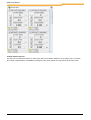
1.2 How to use NORD CON
Attention
For the parameterization and controlling of the devices with NORD CON, your PC requires a
serial interface.
1. Installation
Please start the installation program of NORD CON on the enclosed CD or load the installation program from the
Internet ("http://www2.nord.com/cms/de/documentation/software/software-overview.jsp"). Enter all necessary
information and install NORD CON into the standard directory.
2. Connect
If the frequency inverter is equipped with an RS232 optional interface, it can be directly connected to the PC with a
serial 1-1 cable. In this case, only one frequency inverter can be connected. Each NORDAC vector frequency
inverter features an integrated RS485 interface which can be activated via the control terminals. This interface
allows for configuration of a master/slave bus system with up to 31 devices max. For NORD CON to be connected
to such a bus, an RS232 - RS485 converter will be required.
Attention
If several devices are operated simultaneously, make absolutely sure that a unique USS address
is assigned to each of the devices connected, and that all of them have the same baud rate
setting (see also Operating Instructions of the frequency inverter type involved).
3. Run NORD CON
BU 0000 GB
10
Introduction
In order to start NORD CON, you use the shortcut "NORD CON start" or "Start->Program->Nord->NORD CON 2.1>NORD CON".
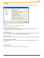
4. Setup of the communication module
In order to set the communication parameters, one must select the appropriate module in the project view. Over the
menu entry "Device-> Parameterize" the parameter dialog of the module can be opened. In the edit field "Port" must
be insert the correct COM port number. After that you have to push the button "Apply". Additional settings are not
necessary for the first application and the window can be closed.
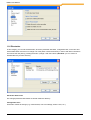
5. Bus scan
After the start of bus scan, all ready and connected devices are searched for. All found devices are represented in
the project tree and in the equipment overview. Subsequently, the first device in the list is marked and the users
can use all device-specific functions.
BU 0000 GB
11
NORD CON Manual
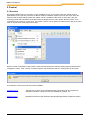
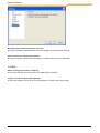
6. Work with the devices
The user can now select the device by clicking the device in the device overview or in the project tree. Functions,
like control or parametrizes, are available in the popup menu of the project tree, the tool bar or the main menu.
BU 0000 GB
12
Introduction
2 Graphic user interface
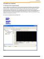
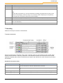
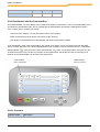
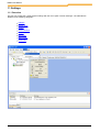
2.1 Structure of the program interface
If you run "NORD CON" for the first time, the window shown down is opened. The window consists of main menu,
toolbars, work area, and the different views. In the work area the different editor windows like parameter windows or
macros are shown. The windows can be positioned freely or be docked at the sides of the work area. In order to
change the position of a docked window, click on the header bar of the window and keep the mouse button
pressed. Subsequently, the new position can be specified with the pointer of mouse. A colored rectangle shows the
current position and dock condition. After releasing the left mouse button, the actual action is implemented. In
addition, the user can dock or undock the window by clicking on the header bar. The layout is stored when closing
application and resumed with the restart.
The interface is divided into the following areas:
Main Menu
Toolbars
Working Area
View "Project"
View "Log"
View "Remote"
BU 0000 GB
13
NORD CON Manual
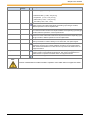
2.2 Main menu
The main menu is the central place for all actions of application. All editor windows register their window-specific
actions there. The actions are divided in categories.
Category "File"
Category "Edit"
Category "Device"
Category "View"
Category "Extras"
Category "Help"
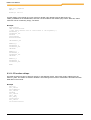
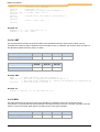
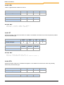
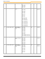
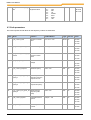
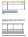
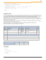
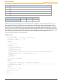
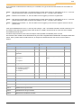
2.2.1 Category "File"
Name of action
Combination Icon Description
of keys
New dataset
The action opens the parameter window for a new device. The user must select
the desired device in a previous window.
New macro
The action opens the macro editor with a new document. If the macro window is
already opened, the user can store the current document.
Attention:
In the current version, only one macro window can be opened!
PLC program
Open
BU 0000 GB
The action opens the PLC editor with an empty document. If a PLC program is
already opened, the user can store the current document.
Ctrl + O
The action opens the file choice dialog in order to open a stored document. The
user selects a document type with the file filter, and selects the file afterwards.
14
Graphic user interface
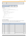
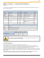
Name of action
Combination Icon Description
of keys
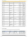
The following types are supported:
Parameter files (*.ndbx, *.db (V1.27))
Scope files (*.scox, *.sco (V1.27))
Macro files (*.ncmx, *.ncm (V1.27))
PLC files (*.awlx, *.awl, *.nstx)
Save
Ctrl + S
Save as...
Export
The action stores the current document with a new name. The action is passed
on to the active editor window and implemented there. Depending upon the type
of editor, different operations can be implemented.
Ctrl + E
Reopen
Print
The action stores the current document. The action is passed on to the active
editor window and implemented there. Depending upon the type of editor,
different operations can be implemented.
The action exports the data active editor windows into a file. The action is
passed on to the active editor window and implemented there. Depending upon
the type of editor, different operations can be implemented.
The action contains a submenu in which the opened last documents are listed.
History is limited to 5. When clicking on one of the files, it is opened again.
Ctrl + P
The action is passed on to the active editor window and implemented there.
Depending upon the type of editor, different operations can be implemented.
This action is deactivated if no editor window is opened or the editor does not
support the action.
Print preview...
The action opens a print preview for the active editor. Depending upon editor, the
printing preview can be differently developed. This action is deactivated if no
editor window is opened or the editor does not support the action.
Quit
The action closes application.
Note
A action is deactivated if no editor window is opened or if the editor does not support the action.
BU 0000 GB
15
NORD CON Manual
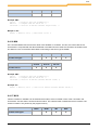
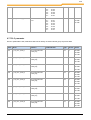
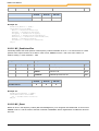
2.2.2 Category "Edit"
Name of action Combinatio Icon Description
n of keys
Undo
Ctrl+Z
The action undoes the last action. The action is passed on to the active editor window
and implemented there. Depending upon the type of editor, different operations can be
implemented.
Cut
Ctrl+X
The action cuts the selected object and copies it into the clipboard. The action is
passed on to the active control member and implemented there. Depending upon the
type of editor, different operations can be implemented.
Copy
Ctrl + C
The action copies the selected object into the clipboard. The action is passed on to
the active control member and implemented there. Depending upon the type of editor,
different operations can be implemented.
Paste
Ctrl + V
The action copies contents of the clipboard to the selected position. The action is
passed on to the active control member and implemented there. Depending upon the
type of editor, different operations can be implemented.
Note:
The action is deactivated if the current control element does not support this action or
the contents of the clipboard cannot be inserted.
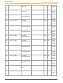
Delete
Ctrl + Del
The action deletes the selected object. The action is passed on to the active control
and implemented there. Depending upon the type of editor, different operations can be
implemented.
Select all
Ctrl + A
The action selects all objects of the active control.
Replace...
Ctrl + H
The action searches for the indicated text and replaces these then by other text. In a
dialog, the appropriate option can be adjusted.
Up
Ctrl + U
The action shifts the delected object one position upward.
Down
Ctrl + D
The action entry shifts the delected object one position downward.
BU 0000 GB
16
Graphic user interface
Note
The action is deactivated if the current control element does not support this action.
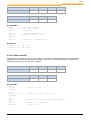
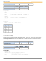
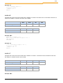
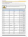
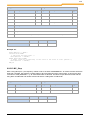
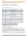
2.2.3 Category "Project"
Name of action
Combination Icon Description
of keys
Save all in file...
The action read all parameters of devices and save it in a file.
Send all from file...
The action opens a file and sends the stored parameters to the devices.
BU 0000 GB
17
NORD CON Manual
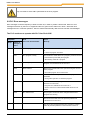
2.2.4 Category "Device"
Name of action
Combin Icon Description
ation of
keys
Rename
Connect
With the action the user can change the name of the selected device.
F2
The action starts or stops the connection to the selected device.
Upload parameters from F3
device
The action uploads the parameters from the device to the PC.
Download parameters to F4
device
The action downloads the parameters from the PC to the device.
Update firmware
The action starts the firmware upload program.
Control
F6
The action opens the "control" window of the selected device in the work area. If
the window was already opened, it is brought into the foreground.
Remote
F8
The action opens the "remote" window of the selected device. If the window was
already opened, it is brought into the foreground.
Parameterize
F7
The action opens the "Parameter" window of the selected device in the work
area. If the window was already opened, it is brought into the foreground.
Oscilloscope
The action opens the "oscilloscope" of the selected device in the work area. If
the window was already opened, it is brought into the foreground.
PLC
The action entry opens the PLC editor of the selected device in the work area. If
the window was already opened, it is brought into the foreground.
Bus scan
Ctrl+F5
The action implements a network scan for the selected communication module.
Note:
With a network scan, all devices are removed from the device list and all devicespecific windows are closed!
BU 0000 GB
18
Graphic user interface
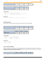
2.2.5 Category "View"
Name of action
Combinati Description
on of keys
Layout -> Standard
The action build the standard - layout of application for all views. The position of
the editor windows is not changed.
Layout -> Standard all
windows
The action build the standard layout of application for all windows including the
work area.
Device report
The action closes or opens the device report.
Project
The action closes or opens the view "project".
Log
The action closes or opens the view "log".
Remote
The action closes or opens the view "remote control".
Toolbar->Standard
The action closes or opens the toolbar "standard".
Toolbar->Device
The action closes or opens the toolbar "device".
Toolbar ->Start
The action closes or opens the toolbar "device".
Macro
The action opens a submenu. In this submenu, all special actions of the macro
editor are listed. The status as well as the execution of the actions is incumbent
on the active macro window. If no window is active, all actions are deactivated.
Oscilloscope
The action opens a submenu. In this submenu, all special actions of the
oscilloscope are listed. The status, as well as the execution of the actions, is
incumbent on the active oscilloscope. If no window is active, all actions are
deactivated.
BU 0000 GB
19
NORD CON Manual
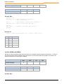
2.2.6 Category "Extras"
Name of action
Combination Description
of keys
Settings
The action opens a window to edit the global settings of the program.
Log
The action opens a submenu. In this submenu all special actions of the view "log"
are listed. The status, as well as the execution of the actions, is incumbent on the
view.
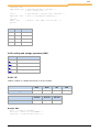
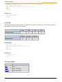
2.2.7 Category "Help"
BU 0000 GB
20
Graphic user interface
Name of action
Combination
of keys
Description
Help
F1
The action opens online help and selects the register map "Contents".
Index
The action opens online help and selects the register map "Index".
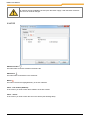
About NORD CON
The action opens a dialog with the program information.
BU 0000 GB
21
NORD CON Manual
2.3 Toolbars
In the toolbars, the most common actions are available for fast access. By clicking the appropriate symbol in the
bar with the mouse, the desired action is specified.
The following toolbars are available:
Standard
Device
Start
2.3.1 Standard
Name of action
Icon
Description
New data set
The action opens the parameter window for a new device. Before the user can open the
dialog, the device must be selected.
New Macro
The action opens the macro editor with an empty document. If a macro is already open,
the user can store the current document.
Attention:
In the current version, only one macro window can be opened!
New PLC program
The action opens the PLC editor with an empty document. If a program is already
opened, the user can store the current document.
Open
The action opens the file dialog in order to open a stored document. The user selects a
document type with the file filter and select the file afterwards. The following types are
supported:
Parameter dataset V1.27 (*.db)
Parameter dataset (*.ndbx)
Scope-File (*.sco)
Scope-File V2.1 (*.scox)
Macro (*.ncmx)
Macro V1.27 (*.ncm)
PLC Program (*.awlx)
Save
The action stores the current document. The action is passed on to the active editor
window and implemented there. Depending upon the type of editor, different operations
can be implemented.
Cut
The action cut the selected object and copies it into the clipboard. The action is passed
on to the active control element and implemented there. Depending upon the type of
editor, different operations can be implemented.
Copy
The action copies the selected object into the clipboard. The action is passed on to the
active control element and implemented there. Depending upon the type of editor,
different operations can be implemented.
Paste
The action copies contents of the clipboard to the selected position. The action is
passed on to the active control member and implemented there. Depending upon the
type of editor, different operations can be implemented.
Note:
BU 0000 GB
22
Graphic user interface
Name of action
Icon
Description
The action is deactivated if the current control element does not support this action or
the contents of the clipboard cannot be inserted.
Delete
The action deletes the selected object. The action is passed on to the active control
member and implemented there. Depending upon the type of editor, different
operations can be implemented.
Up
The action shifts the selected object a position upward.
Down
The action shifts the selected object a position downward.
Preview
The action opens a print preview for the active editor. Depending upon editor, the
printing preview can be differently developed. This action is deactivated if no editor
window is opened or the editor does not support the action.
Print
The action print the content from the active editor. This action is deactivated if no editor
window is opened or the editor does not support the action.
Fast print
The action print the content from the active editor without the print dialog. This action is
deactivated if no editor window is opened or the editor does not support the action.
Settings
The action opens a window to edits the global settings of the program.
2.3.2 Device
Name of action
Bus scan
Icon
Description
The action implements a network scan for the selected communication module.
Note:
With a network scan, all devices are removed from the device list and all devicespecific windows are closed!
Connect
The action connects or disconnects the connection to the selected device.
Control
The action opens "control" window of the selected device in the work area. If the
window was already opened, it is brought into the foreground.
Remote
The action opens "remote" window of the selected device. If the window was already
opened, it is brought into the foreground.
Parameterize
The action opens the "parameter" window of the selected device in the work area. If
the window was already opened, it is brought into the foreground.
Oscilloscope
The action opens the "oscilloscope" of the selected device in the work area. If the
window was already opened, it is brought into the foreground.
Plc
The action opens the PLC editor of the selected device in the work area. If the window
was already opened, it is brought into the foreground.
Upload parameters from
device
The action uploads the parameters from the device to the PC.
Download parameters to
device
The action downloads the parameters from the PC to the device.
BU 0000 GB
23
NORD CON Manual
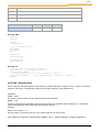
2.3.3 Start
Name of action Combinatio Icon Description
n of keys
PLC settings
The action opens the settings of the PLC.
Compile
Shift + F7
The action starts the translation of a PLC program.
Programming
Shift F8
The action loads a PLC program to the Device.
Run
F9
The action runs a PLC program or a macro. The action is passed on to the active
editor window and implemented there. Depending upon the type of editor, different
operations can be implemented.
Cancel
F11
The action terminates running a PLC program or macro. The action is passed on to
the active editor window and implemented there. Depending upon the type of editor,
different operations can be implemented.
Next
F12
The action executes the next instruction. The action is passed on to the active editor
window and implemented there. Depending upon the type of editor, different
operations can be implemented.
Debug
Shift + F5
The action runs the PLC program with the debug mode.
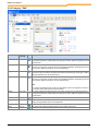
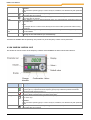
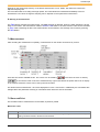
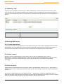
2.4 View "Project"
In View "Project", all devices of the project are shown in a tree structure. It can be closed or opened with the main
menu option "View->Project ". With the help of the mouse, you can navigate between the individual devices. If the
view possesses the input focus, you can additionally select a device with the arrow keys "up" and "down ". If the
pointer of mouse is over a device entry, a reference about the type of device and fieldbus address is indicated. After
the selection of a device, the user can execute all actions with the tool bar as well as the popup menu. If an action
is shaded grey, the selected devices do not support. The popup menu is opened by clicking the right mouse button
in the view.
BU 0000 GB
24
Graphic user interface
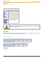
Status of device
The connection to the device is online
The connection to the device is offline
Used topics:
Structure of popup menu, Structure of the program interface, Main menu, Toolbars, View "Log", View "Remote",
Docking and Undocking
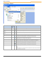
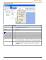
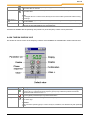
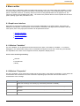
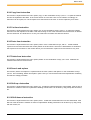
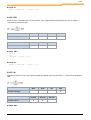
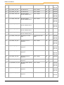
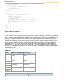
2.4.1 Structure of popup menu
The representation shows the popup menu of the project view. The menu always refers to the selected nodes in the
project tree.
BU 0000 GB
25
NORD CON Manual
Name of action
Combination of Description
keys
Rename
With the action the user can change the name of the selected device.
Upload parameters from F3
device
The action uploads the parameters from the device to the PC.
Download parameters
to device
The action downloads the parameters from the PC to the device.
F4
Update firmware
The action starts the firmware upload program.
Control
F6
The action opens then "control" window of the selected device in the work area.
If the window was already opened, it is brought into the foreground.
Remote
F8
The action opens the „remote" window of the selected device. If the window
was already opened, it is brought into the foreground.
Parameterize
F7
The action opens the "parameter" window of the selected device in the work
area. If the window was already opened, it is brought into the foreground.
Oscilloscope
The action opens the „oscilloscope" of the selected device in the work area. If
the window was already opened, it is brought into the foreground.
PLC
The action opens the PLC editor of the selected device in the work area. If the
window was already opened, it is brought into the foreground.
Bus scan
Ctrl + F5
The action implements a network scan for the selected communication
module.
Note:
With a network scan, all devices are removed from the device list and all
device-specific windows are closed!
BU 0000 GB
26
Graphic user interface
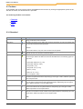
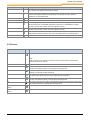
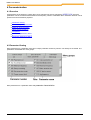
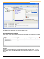
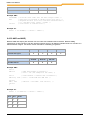
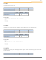
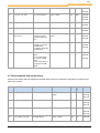
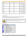
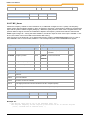
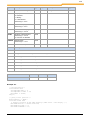
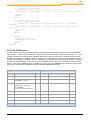
2.5 View "Messages"
The view contains a list of all „NORD CON" messages. The entries are displayed by default time ascending. The
sortation can be adjusted by clicking on a column header. Following filters available are for the filtering:
Filter
Icon Description
Error
This filter is enabled, displays all errors. In addition, it shows the number of errors in the caption of
the button.
Warning
This filter is enabled, all warnings are displayed. The number of warnings is displayed in the caption
of the button.
Information
This filter is enabled, all information will be displayed. The number of information is displayed in the
caption of the button.
System
This filter is enabled, all messages of the "System" category are displayed.
Communicati
on
This filter is enabled, all messages of the "Communications" category are displayed.
PLC
This filter is enabled, all messages of the "PLC" category are displayed.
Macro
This filter is enabled, displays all messages in the "Macro" category.
Parameter
This filter is enabled, displays all messages in the "Parameter" category.
The messages can be saved or deleted via the popup menu (right mouse button). These actions can be carried out
via the main menu ("Extras/Messages").
Name of action
Description
Delete
The action deletes the list.
Save
The action stores the entries into a file.
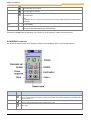
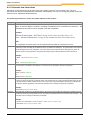
2.6 View "Remote"
The view "remote" contains all windows of the function „Remote". The view opens automatically when opening the
first window and closes after closing the latest. The view can be docked or undocked like all views to the work area.
If the view was closed by the user, it can be opened by the action "Remote" again. The new windows are always
docked to the left side of the last window. With the help of the mouse, it can be undocked or docked again. If the
view is opened for the first time with the menu "View->Remote", each device in the list the window "Remote" is
opened automatically.
BU 0000 GB
27
NORD CON Manual
Note
Windows of type "Remote" can be docked only into the view "Remote".
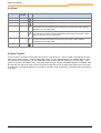
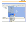
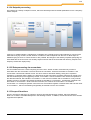
2.7 Docking and Undocking
With the new design of NORD CON, the user has the possibility to adapt the layout of the surface to their own
requirements. In principle, you can undock each view and editor window and position them freely on the screen. For
this, the user must press the left mouse button over the title border and pull the colored rectangle to the desired
position. After releasing the mouse button, the view or editor windows remains in those positions as independent
windows . With the editor windows, there is additionally the possibility - with the popup menu, which opens when
clicking with the right mouse button on the title border, to undock the windows. The docking functions are similar to
the undocking functions. The colored rectangle indicates in each case the current docking position.
Type of window
Rule
View of main window(e.g. Project, Logs,
Remote)
The views of the main window can be docked only to the left, right and/or
lower edge of the work area. Within these windows, there are no rules
and the user can select the position freely.
Editor window (e.g. Macro editor, Parameter
window, Oscilloscope)
The editor windows can only be docked into the work area. The
adjustment is fixed however on down and/or above, or as register map.
Views of the Macro editor
The views of the macro editor can be docked only to the macro window.
The adjustment here is fixed on left, right or down. Within the views, no
rules are defined.
Views of the oscilloscope
The views of the oscilloscope window can be docked only to the
oscilloscope window. The adjustment here is fixed on left, right or down.
Within the views no rules are defined.
„Remote" windows
"Remote" windows can only be docked to the view "Remote". Here the
adjustment is fixed on left.
BU 0000 GB
28
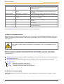
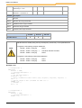
Graphic user interface
Docking position left
BU 0000 GB
29
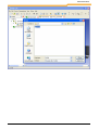
NORD CON Manual
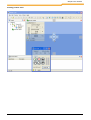
Docking position right
BU 0000 GB
30
Graphic user interface
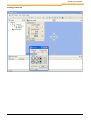
Docking position down
BU 0000 GB
31
NORD CON Manual
Docking position up
BU 0000 GB
32
Graphic user interface
Docking position tab
BU 0000 GB
33
NORD CON Manual
3 Communication
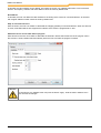
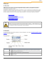
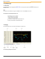
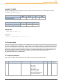
3.1 Overview
In order to start a connection to a device, you must insert the appropriate communication module in the project.
After the installation, a USS module is configured. With the action "Parameterize" the user can modified the
parameters of the module.
Presently the following communication modules are supported:
USS over serial interface
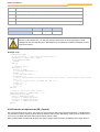
3.2 USS
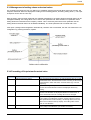
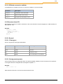
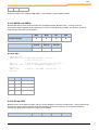
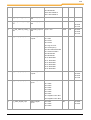
3.2.1 General settings
Name
In the edit field, the user can assign a name for the communication module.
Port
In the communication window, you can choose the COM-Ports of the computer where the inverter is connected to.
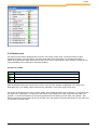
Telegram error
The user defines the max number of allowed telegram errors.Telegram errors occur if the content of a telegram is
not correct. That means the answer does not fit to the parameter order. Normally, each parameter order is
answered after 2 telegrams. The number of allowable telegram errors is the number of tries before the error
message appears.
Bus error
The user defines the max number of acceptable bus errors. The bus error appears in the case when the receiving
telegram or the sending telegram was wrong. Incorrect telegrams are ignored. Here you can program the max
number of incorrect bus telegrams before the error message is generated. In an installation with many interferring
signals, the setting of acceptable errors should be programmed to a higher number.
Simulation of Hardware
With this feature, the user activates or deactivates the simulation of the connected hardware.
BU 0000 GB
34
Communication
Attention
All changes are only available if the user push the button "apply". With the button "Restore" then
user can undo all changes.
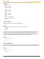
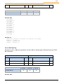
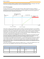
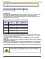
3.2.2 Bus scan
Baud rate
In the selection box, the user can choose the communication speed of the serial interface. The same value must be
chosen on the frequency inverter. When using multiple frequency inverters, the setting must be identical on all
connected devices. The Baud rates over 115200 Bit/s are user specific Baud rates and not by all devices are
supported.
Attention
Older serial PC interfaces are sometimes not able to justify the accurate user specific Baud rate.
From this reason no connection can be made to the device.
Bus-Scan with all baud rates
With the action, the user activates or deactivates the bus scan with all baud rates. If the baud rate of the connected
device is unknown, the search with all baud rates can find the right one to start communication.
Starting baud rate
In the selection box, the user can define the baud rate for start of the baud rate search.
Starting address
BU 0000 GB
35
NORD CON Manual
In this field, the USS address can be defined, from where the search run of NORD CON starts to find connected
devices. All frequency inverters with lower address cannot be found by NORD CON.
End address
In this field, the user can define the USS address for the ending of the search for connected devices. All inverters
with a higher address number cannot be found by NORD CON.
Stop all connected devices
With the action, the user can activate or deactivate the stopping (disable) of connected devices. When this function
is active, all enabled devices are stopped if the interface of the device is programmed to "bus".
Automatic device search after start of program
With this action the user can activate or deactivate the automatic device search after start of the program. When
this function is active, NORD CON automatically starts the bus scan after the program is started.
Attention
All changes are only available if the user push the button "apply". With the button "Restore" then
user can undo all changes.
BU 0000 GB
36
Communication
3.3 USS over TCP
3.3.1 General settings
Name
In the edit field, the user can assign a name for the communication module.
Telegram error
The user defines the max number of allowed telegram errors.Telegram errors occur if the content of a telegram is
not correct. That means the answer does not fit to the parameter order. Normally, each parameter order is
answered after 2 telegrams. The number of allowable telegram errors is the number of tries before the error
message appears.
Bus error
The user defines the max number of acceptable bus errors. The bus error appears in the case when the receiving
telegram or the sending telegram was wrong. Incorrect telegrams are ignored. Here you can program the max
number of incorrect bus telegrams before the error message is generated. In an installation with many interfering
signals, the setting of acceptable errors should be programmed to a higher number.
USS over TCP
If this option is enabled, NORD CON attempts to establish communication with a Ethernet bus module (eg Profinet,
Ethernet IP) via LAN. In addition, the connected devices must be configured in the device list (see TCP).
Stop all found devices
If this option is enabled, each detected device will be sent the "Disable" command after search. Provided that the
device can be controlled via bus.
Automatic search at program start
If this option is enabled, the device search is initiated after the program start.
BU 0000 GB
37
NORD CON Manual
Attention
All changes are only available if the user push the button "apply". With the button "Restore"
then user can undo all changes.
3.3.2 TCP
Add bus module
The button adds a new bus module in the device list.
Add device
The button adds a new device in the device list.
Delete
The button removes the highlighted entry in the list of devices.
Value - bus module (Address):
In the column you have to enter the IP address of the bus module.
Value - device:
In the column you have to enter the slot on the device (see following table).
BU 0000 GB
38
Communication
Slot 1
Slot 2
Slot 3
Slot 4
System bus
address 32
System bus
address 34
System bus
address 36
System
System bus
bus
address 40
address 38
or
Slot 5
Slot 6
Slot 7
Slot 8
System bus
address 42
System bus
address 44
System bus
address 46
SK 5xxE over
TU3
Sample:
Bus module
Slot 1
Slot 2
Slot 3
Slot 4
SK TU3-EIP V1.2
SK 5xxE
not available
not available
not available
SK CU4-EIP V1.2
SK 5xxE
SK 5xxE
SK 5xxE
SK 5xxE
SK TU4-EIP V1.2
SK 2xxE
SK 2xxE
SK 2xxE
SK 2xxE
SK CU4-PNT V1.2
SK 19xE
SK 19xE
SK 19xE
SK 19xE
SK 18xE
SK 18xE
SK 18xE
SK 18xE
SK TU3-PNT V1.2
Additional - device:
In this column, the user specifies the number of IO extensions.
Attention
Please note that you need access rights for parameter changes or control via the bus module.
To set it accordingly please check the data sheet of your field bus module.
Attention
All changes are only available if the user push the button "apply". With the button "Restore"
then user can undo all changes.
BU 0000 GB
39
NORD CON Manual
4 Parameterization
4.1 Overview
All parameters of the frequency inverter that can be changed can also be changed by NORD CON. All of the
parameters can be stored and retransmitted to the frequency inverter. Parameters which have been read out can be
printed out for documentation purposes.
Parameter Viewing
How to manipulate parameters
Selective parameterization
Off-line Parameterization
Comparison
Parameter upload from device
Parameter download to device
4.2 Parameter Viewing
Each parameter has a parameter name and a unique parameter number by which it can directly be accessed. The
parameters are devided into menu groups.
Each parameter has a parameter value and parameter characteristics :
BU 0000 GB
40
Parameterization
When a parameter has been selected, values of all parameter sets, if it can be set differently in the sets , are
displayed.
4.3 How to manipulate parameters
The selected parameter is read out and the value transferred to the 'Current Setting' box.Management of the
parameters of a frequency inverter is ensured by databases. These databases can be stored, printed out or
manipulated again at a later date.
Note
The menu "Parameterize" is indicated only if a parameter window were marked.
NORD CON features two ways of parameter manipulation:
Aktion
Place
Description
New
File -> New -> Dataset
The current database is re-initialized, in other words the current
and the new settings are deleted.
Open
File -> Open
Any database that was saved can be reopened.
Save
File -> Save
The current database is saved by the current name.
Save us...
File -> Save us...
The current database is saved with a new name.
Print preview...
File -> Print preview...
The current parameter settings are printed out.
Read all parameter or
Read all
Parameterize -> Read -> All
Parameter
All of the parameters of the frequency inverter are read out and
entered into the database.
Read actual menu
group
Parameterize -> Read -> Actual
menu group
The parameters of the selected menu group are read out and
entered into the database.
Send new settings
Parameterize -> Send -> new
Values
All parameters for which a new value was entered in the 'New
settings' box are transmitted to the frequency inverter. A
BU 0000 GB
41
NORD CON Manual
Aktion
Place
Description
selection is possible as to whether this operation is to be
performed on all parameters or only on those belonging to the
current menu group.
Send Factory settings
Parameterize -> Send -> Reset
values
The settings transmitted will be the default settings of all
parameters or of the parameters of the current menu group
respectively
Selection Enable
Parameterize -> Selection ->
Release
All of the parameters (or those included in the current menu
group respectively), are enabled.
Selection Disable
Parameterize -> Selection -> no None of the parameters (or of those belonging to the current
Release
menu group), are enabled.
Standard
Button "Standard"
The default value is allocated to the currently selected
parameter.
Send
Button "Send"
The value "new setting" of the current parameter is transferred
to the inverter
Read
Button "Read"
The selected parameter is read out and the value transferred to
the 'Current Setting' box.
With the Auto-read option the selected parameter is read out automatically.
4.4 Selective parameterization
NORD CON allows for masking some parameters or other, a feature which may facilitate manipulation or serve the
purpose of restricting parameter readout or transmission to those which remain unmasked or in other words have
been filtered out.
Note
When a filter has been activated, all operations are executed only on those parameters which are
displayed.
Before any parameter can be masked the enable command must be inactivated. This can be done using the
checkbox preceding the parameter, or via the Selection menu. The Filter box provides for the setting options
mentioned below :
Selection only Only the enabled parameters are displayed (i.e. where the check box preceding the parameter
was clicked upon once).
No standard Only the parameters with a value that is different from the standard setting are displayed.
Info parameters
Yes
Information parameters are displayed.
No
Information parameters are not displayed.
Only Information parameters are displayed exclusively.
4.5 Off-line Parameterization
Off-line parameterization implies that a database is manipulated which is not allocated to any frequency inverter
connected.
BU 0000 GB
42
Parameterization
Off-line parameterization is started via the database menu in the main window.
Name
Description
New
A new database can be created. The new database is allocated to a frequency inverter type which is set using a
selection box.
Open
Any database that was read into memory can be opened and manipulated.
4.6 How to compare parameters
The report shows the differences and/or thing in common of two data record. In principle only data records of one
device family can be compared. The parameters are represented in form of a list. If two parameter values are
different, the line with a grey bar is marked. Additionally it is examined whether a value differs from the default value.
In this case the value is red represented.
Online / Offline compare
Connect the device with NORD CON. Afterwards the parameter window must be opened and it be recommended
to readout all parameters. With the parameter filters you can limit the selection of the parameters. Over the menu
option " Parameterize - > Compare" you can generate a report. After the call of the function the user must select a
stored data record. If the selected parameters are to be used as backup, the user must store afterwards the current
data record. Thereupon the report is generated and showed.
Attention
As reference for the parameters and the default values the configuration of the equipment is used. A
data record with the configuration of the equipment not agrees selected, possibly non-existent
parameters are empty represented and marked as difference.
Offline / Offline compare
For the comparison a stored or new data record must be opened. With the parameter filters you can limit the
selection of the parameters. Over the menu option " Parameterize - > Compare" you can generate a report. After
the call of the function the user must select a stored data record.
Attention
As reference for the parameters and the default values the configuration of the opened parameter set
is used. A data record with the configuration of the equipment not agrees selected, possibly nonexistent parameters are empty represented and marked as difference.
4.7 Parameter upload from device
The function loads the parameters of a device to the PC and then stores the values in a parameter file. The action
can be started through the tool bar "Device" or over the menu option "Device/Parameter upload from device". After
executing the function that opens following window and the upload the parameter starts automatically.
Communication errors occur during the transfer, they displayed in the message window. At the end of the transfer
the user prompts one to enter a file name for the file. The user must confirm with "Save" to store the values.
BU 0000 GB
43
NORD CON Manual
4.8 Parameter download to device
The function opens a parameters file on the PC and sends all values to the device. The action can be started via the
tool bar "Device" or "Device/parameter download to the device" menu item. After executing the function, the
following window and a file dialog opens. In this dialog selects the user the parameter file and confirm with "Open".
The program checks whether the parameter file to the selected device fits. In this case the download will start.
BU 0000 GB
44
Parameterization
BU 0000 GB
45
NORD CON Manual
5 Control
5.1 Overview
The program NORD CON can be used to control NORDAC vector. To use this function the inverter must be
parametriesed in the right way. Because of different settings of different inverter types the user must check the
manual to find the right settings. Before the inverter can be controlled the Bus-scan must be done. After the
scanning process has finished all connected inverter are displayed in the main window. Now the inverter to be
controlled can be chosen by mouse click. The window „control" can be opened via "device/control (F6) in the main
menu or via pull-down menu (right mouse click).
Now the control configuration of the inverter is read and checked with the standard setting (setting/control/control
configuration check). If the "control" of inverter limited or impossible there will be a warning note on the screen.
In the window „Control" there are two versions available:
Standard Control
The frequency inverter can be released and the setting value can be increased or
decreased. Direction change and error acknowledge is possible, too.
Detailed Control
Mit diesem Fenster können sämtliche Steuerungsmöglichkeiten ausgenutzt werden.
BU 0000 GB
46
Control
5.2 Standard control
Using the Standard Control the following functions are available:
Enable of the frequency inverter
Increase or decrease of the setting value
Change of direction
Error Acknowledge
To use this functionality, the inverter must be programmed for control via bus. You can find the required parameter
and settings in the manual available for each inverter type.
On the „Standard" display only the first setting value and first actual value are displayed. The form of value is fixed
for each configuration.
By pressing the button 'Detail' you can switch to the extended control function.
5.3 Detailed control
5.3.1 Overview
In the mode „Detailed Control" some extra functions are available:
Setting of control word and display of status word
Management of setting values and actual values
Sending of broadcast telegramme
Choice of different parameter sets
Automatic sending of control word and setting values
BU 0000 GB
47
NORD CON Manual
5.3.2 Control
The controlword is displayed as a hexadecimal value in the field „control word". By entering a new value
(hexadecimal) the user can change the control word. For a bit-coded setting of control word the user can open up a
new editorial window by pressing the button "control word edit". In this window the control word is displayed in bits.
The status word is displayed hexadecimal in the screen „status word". To display the status word in the bit
resolution the button „bit orientated detail view" can be chosen. The status is displayed in the status line of the
status machine as clear text.
BU 0000 GB
48
Control
5.3.3 Management of setting values and actual values
For controlling the inverter the user can define up to 3 different setpoints and actual values (see user manual). The
setpoints and actual values are displayed according to the formatting (Button „formatting setting value x"). The input
of setpoins can be done in same way.
With the option „setting/control/ parameter set individual management" the setting values and actual values can be
managed individually. So setting values can be set for each parameter set. With activation of a parameter set its
setting values are transmitted to the frequency inverter. This is necessary because for each parameter set the
setting values and actual values can be defined individually. The active parameter set is marked with a star.
If the option „setting/control/configuration automatically checked" was not activated, the user can transmit the new
configuration by pressing the button „update".
5.3.4 Formatting of Setpoint and/or actual value
Char
Name
Description
"%"
16 Bit standardised values
This standardisation transforms the setpoint/actual value to a 16 Bit
standardised value. Standardisation means a scaling of value range
and is between -200% and 199% of a basic value (e.g. nominal
frequency).
"16"
16 Bit not standardised
By this formatting the setpoint and actual value are transformed to 16
Bit value and transmitted to inverter and displayed without any
scaling.
"B"
DigInBits
By this Formatting the setpoint and actual value are transformed to 8
Bit value. The bit status is displayed individual in check boxes. In
these check boxes each bit of setting value can be changed.
"L"
32 Bit Low-Word
By this formatting the setpoint and actual value are taken as the low
word (16 Bit) of a 32 Bit word..If there is another setpoint or actual
value parametriesed with formatting "32 Bit High-Word", then both
values are combined in the top display. The setting value can be
given as a 32 Bit value.
"H"
32 Bit High-Word
By this formatting the setpoint and actual value are taken as the high
word (16 Bit) of a 32 Bit word. (see "32 Bit Low-Word").
BU 0000 GB
49
NORD CON Manual
"P"
16 Bit Posicon Arr control clamps
(SK7xx, Vector CT with Posicon)
By this formatting the setpoint and actual value are taken as the
„Posicon position array". The meaning of each bit you can find in the
Posicon manual. This option is only available for inverter with Posicon
functionality.
"I"
16 Bit Posicon Inc control clamps
(SK7xx, Vector CT with Posicon)
By this formatting the setpoint and actual value are taken as „Posicon
position increment array". You can find the meaning of each bit in the
Posicon manual. This option is only available for inverter with Posicon
functionality.
"32"
32 Bit standardised (SK7xx, Vector CT By this formatting the setpoint and actual value is taken as an 32 Bit
with Posicon)
value without standadisation. This option is only available for inverter
with Posicon functionality.
5.3.5 Control word
The present status word is displayed with each bit in the window „status word". All bits are listed in a table
including bit number, name and status. According to bit value and function there is a coloured LED shown.
Importance of LEDs:
LED
Importance
The Bit is set and/or the inverter is enabled.
An error is active or an enable signal is missing.
The Bit is not set.
With the standard setting the status word is read in cycles and the changes are displayed in the window. For
deactivating the cyclic reading switch off the function „automatic" in the menu (right mouse click).
The window is docked left next to the „control" window. If the window should be free on desktop, you should choose
the popup menu "docking/no". To save space the window can be added as an index card next to the index card
„general". To do this the window must be moved (pressed left mouse button) over the index card "general". After
release of the button the window is shown as an index card. With double click (left mouse button) on the index card
you get back to window mode.
BU 0000 GB
50
Control
5.3.6 Status word
The present control word is displayed with each bit in the window „status word". All bits are listed in a table
including bit number, name and status. According to bit value and function there is a coloured LED shown. If
inverter is programmed to USS control then the bits can be set by control buttons. Each change of control word is
sent immediately to the inverter (see „automatic sending").
Importance of LEDs:
LED
Importance
The Bit is set and/or the inverter is enabled.
An error is active or an enable signal is missing.
The Bit is not set.
With the standard setting the control word is read in cycles and the changes are displayed in the window. For
deactivating the cyclic reading switch off the function „automatic" in the menu (right mouse click).
The window is docked left next to the „control" window. If the window should be free on desktop, you should choose
the popup menu "docking/no". To save space the window can be added as an index card next to the index card
„general". To do this the window must be moved (pressed left mouse button) over the index card "general". After
release of the button the window is shown as an index card. With double click (left mouse button) on the index card
you get back to window mode.
BU 0000 GB
51
NORD CON Manual
BU 0000 GB
52
Control
6 Remote
6.1 Overview
NORD CON can simulate the control unit of the respective frequency inverter. For this purpose the frequency
inverter transfers the content of its display to NORD CON. The key functions are simulated on the PC and
transmitted to the frequency inverter.
The frequency inverter can only be controlled via the Remote, if it has not previously been enabled via the control
terminals or via a serial interface (P509 = 0 and P510 = 0). In addition, for this the parameter “PotentiometerBox
Function” (P549) must not be set to function {4} “Frequency addition” or function {5} “Frequency subtraction”.
Remote Standard
Remote NORDAC SK2xxE
Remote NORDAC SK7xxE/SK5xxE/SK300E
Remote NORDAC vector mc
Remote NORDAC vector ct
Note
NORDAC vector can be controlled via the keyboard (enable, setpoint +/-, phase sequence etc.). As
the timeout monitoring function is not active in this mode, any breakdown of the connection between
PC and frequency inverter will make further control impossible.
6.2 Standard
The standard window for the function "Remote" is used for all Devices, if the option "Use device-specific remote
windows " were not activated.
Name
Enable
Disable
Change dir
BU 0000 GB
Icon
Description
Switching on the frequency inverter. The frequency inverter is now enabled with the set jog
frequency (P113). A preset minimum frequency (P104) may at least be provided. Parameter
>Interface< P509 and P510 must = 0.
Switching off the frequency inverter. The output frequency is reduced to the absolute minimum
frequency (P505) and the frequency inverter shuts down.
The motor rotation direction changes when this key is pressed. "Rotation to the left" is indicated
by a minus sign.
53
NORD CON Manual
Attention:
Take care when operating pumps. screw conveyors, ventilators, etc. Block the key with parameter
P540.
Press key to increase the frequency. During parameterisation, the parameter number or
parameter value is increased.
Press the key to reduce the frequency. During parameterisation, the parameter number or
parameter value is reduced.
Press "ENTER" to store an altered parameter value, or to switch between parameter number or
parameter value.
Up
Down
Enter
Note:
If a changed value is not to be stored, the key can be used to exit the parameter without storing
the change.
Change Dir +
Stop
Enter + Start
By simultaneously pressing the STOP key and the "Change direction key” , an quick stop
can be initiated.
If the inverter is enabled via the "ON" key, the parameterisation mode can be reached by
pressing the ON and ENTER keys simultaneously.
All functions available with the operating unit (control box) of the frequency inverter can be performed.
6.3 SK 200E/SK 190E/SK 180E
The window for remote control of the frequency inverters of the NORDAC SK 200 E series looks like this:
Name
Enable
Disable
Change dir
Up
BU 0000 GB
Icon
Description
Switching on the frequency inverter. The frequency inverter is now enabled with the set jog
frequency (P113). A preset minimum frequency (P104) may at least be provided. Parameter
>Interface< P509 and P510 must = 0.
Switching off the frequency inverter. The output frequency is reduced to the absolute minimum
frequency (P505) and the frequency inverter shuts down.
The motor rotation direction changes when this key is pressed. "Rotation to the left" is indicated
by a minus sign.
Attention:
Take care when operating pumps. screw conveyors, ventilators, etc. Block the key with parameter
P540.
Press key to increase the frequency. During parameterisation, the parameter number or
parameter value is increased.
54
Remote
Down
Press the key to reduce the frequency. During parameterisation, the parameter number or
parameter value is reduced.
Press "ENTER" to store an altered parameter value, or to switch between parameter number or
parameter value.
Enter
Note:
If a changed value is not to be stored, the key can be used to exit the parameter without storing
the change.
Change Dir +
Stop
Enter + On
By simultaneously pressing the STOP key and the "Change direction key” , an quick stop
can be initiated.
If the inverter is enabled via the "ON" key, the parameterisation mode can be reached by
pressing the ON and ENTER keys simultaneously.
All functions available with the operating unit (control box) of the frequency inverter can be performed.
6.4 SK 700E/SK 500E/SK 300E
The window for remote control of the frequency inverters of the NORDAC SK 700/500/300 E series looks like this:
Name
Enable
Disable
Change dir
Icon
Description
Switching on the frequency inverter. The frequency inverter is now enabled with the set jog
frequency (P113). A preset minimum frequency (P104) may at least be provided. Parameter
>Interface< P509 and P510 must = 0.
Switching off the frequency inverter. The output frequency is reduced to the absolute minimum
frequency (P505) and the frequency inverter shuts down.
The motor rotation direction changes when this key is pressed. "Rotation to the left" is indicated
by a minus sign.
Attention:
Take care when operating pumps. screw conveyors, ventilators, etc. Block the key with parameter
P540.
BU 0000 GB
55
NORD CON Manual
Up
Press key to increase the frequency. During parameterisation, the parameter number or
parameter value is increased.
Press the key to reduce the frequency. During parameterisation, the parameter number or
parameter value is reduced.
Press "ENTER" to store an altered parameter value, or to switch between parameter number or
parameter value.
Down
Enter
Note:
If a changed value is not to be stored, the key can be used to exit the parameter without storing
the change.
Change Dir +
Stop
Enter + On
By simultaneously pressing the STOP key and the "Change direction key” , an quick stop
can be initiated.
If the inverter is enabled via the "ON" key, the parameterisation mode can be reached by
pressing the ON and ENTER keys simultaneously.
All functions available with the operating unit (control box) of the frequency inverter can be performed.
6.5 NORDAC vector mc
The window for remote control of the frequency inverters of the NORDAC vector mc series looks like this:
Name
Enable
Disable
Change dir
BU 0000 GB
Icon
Description
Switching on the frequency inverter. The frequency inverter is now enabled with the set jog frequency
(P113). A preset minimum frequency (P104) may at least be provided. Parameter >Interface< P509
and P510 must = 0.
Switching off the frequency inverter. The output frequency is reduced to the absolute minimum
frequency (P505) and the frequency inverter shuts down.
The motor rotation direction changes when this key is pressed. "Rotation to the left" is indicated by a
minus sign.
56
Remote
Up
Down
Enter
Attention:
Take care when operating pumps. screw conveyors, ventilators, etc. Block the key with parameter
P540.
Press key to increase the frequency. During parameterisation, the parameter number or parameter
value is increased.
Press the key to reduce the frequency. During parameterisation, the parameter number or
parameter value is reduced.
Press "ENTER" to store an altered parameter value, or to switch between parameter number or
parameter value.
Note:
If a changed value is not to be stored, the key can be used to exit the parameter without storing the
change.
Change Dir +
Stop
Enter + On
By simultaneously pressing the STOP key and the "Change direction key” , an quick stop can
be initiated.
If the inverter is enabled via the "ON" key, the parameterisation mode can be reached by
pressing the ON and ENTER keys simultaneously.
All functions available with the operating unit (control box) of the frequency inverter can be performed.
6.6 NORDAC vector ct
The following functions are available for remote control of the NORDAC vector CT series:
All functions available with the operating unit (control box) of the frequency inverter can be performed.
BU 0000 GB
57
NORD CON Manual
7 Oscilloscope
7.1 Overview
The oscilloscope function integrated inNORD CON can show process data of an NORDAC vector as an
arithmetic chart.
Note:
This option is not available in all types of NORDAC vector ct and NORDAC vector mc!
The features of oscilloscope-function are:
Monitoring of up to 4 channels
Many different ways of trigger
Scaling of each measurement
Calculation of average values, effective value, etc.
Save, print and export of measurement data
7.2 Display
The oscilloscope function can measure and display 4 channels max:
The following settings can be done:
BU 0000 GB
58
Oscilloscope
Name
Description
Auto
Automatic Scaling of all measured data
Offset
Selection of display detail (displace of all data in x- or y-direction)
Zoom
Display size (Zoom of all data)
Note:
With the right mouse button you can choose between modi 'Move' and 'Measurement', if the mouse
pointer is on the display. In 'Move' mode you can choose the detail of display by mouse pointer by
pressing the left mouse button while moving over the display.
Auto scrolling
With this option during a recording the time axis is scrolled automatically to the last point.
Resolution
In this combination field the user can change the scaling of the time axis.
Comment
Additional information field, in that further information to the series of measurements to be stored can
(max. 255 indications).
Cursor
Execution of measurement
7.3 Handling
Follow the next steps to execute a measurement:
1. Choise of channels
There is a popup menu to make the choice of the 4 channels. There is a color referring to each channel. Each
channel can be switched on and off by checkbox's. The resolution and offset can be chosen for each channel
separately. Displaying the results of measurement the values of the vertical axis of each channel can be chosen
and indicated.
Importance of measure value
Mesure value
Description
(=P[Number]) [Name]
The value of this measuring function is updated in the time slot pattern by approx. 100
ms and corresponds to the value indicated of the parameter.
[Name]
The value of this measuring function is updated in a time slot pattern by approx. 100
ms.
(˜ P[Number]) [Name]
The value of this measuring function is updated in a time slot pattern by approx. 50 ms.
(~P[Number]) [Name]
The value of this measuring function is updated in a time slot pattern of approx. 250 µs.
BU 0000 GB
59
NORD CON Manual
2. Setting of trigger
The trigger starts the measurement. First choose the source of trigger. Trigger sources can be measurement
values, digital inputs, status of inverter, etc. The starting conditions are defined by trigger level resp. trigger edge.
ATTENTION
The increments of the trigger levels are different depending on the trigger source. Therefore not every
value can be set. After starting a recording, the closest possible values is calculated and set.
Time between two measured values is set by sampling rate. Numbers of measured values and sampling rate
define the time of sampling.
The Pre-trigger/Delay set the beginning of the measurement in relation to the trigger event.
Note:
The dynamic of measured values defines the best rate of sampling: fast changing values need a low sampling rate.
The number of measured values defines the time of sending the values from inverter to NORD CON.
3. Sampling modes
The oscilloscope has 2 differently modes. The user can choose between "Single" and "Roll" mode. The "Single"
mode is the standard mode. In this mode starts a recording with the current trigger settings. The recording time
BU 0000 GB
60
Oscilloscope
depends on the oscilloscope memory of the device and amounts to max. 2000s. The values are noted in the
adjusted sampling rate.
The roll mode makes a recording over larger period. The noted values are transferred immediately to the PC.
Therefore the user cannot change the sampling rate. It depends on the speed of the transmission.
4. Starting of measurement
The Start-Button activates the measurement. The event of trigger is detected. When the event appears the record
starts in the inverter. The transmission of data to NORD CON starts in the same moment. This can be cancelled
by Stop. After transferring all data a new measurement can be started or new settings can be done by pressing
the New-Button.
7.4 Measurement
After recording the measurement completely, measurements on the results can be done by cursors.
There are two cursors available for this. The cursors can be moved by
. The choice of cursor is done by
. To choose the mode `move`and `measurement`by right mouse button the pointer has to be on display.
In the measure mode the cursors can be set by left mouse button.
The values of the measured lines 1 and 2 are displayed on cursor 1 and cursor 2. Additionally the calculations like
average values are performed. Pressing on calculation button starts the shift of calculation.
7.5 Save and Print
The recorded series of measurement can be saved, exported or printed.
Menu item "File"
Name
Description
Open
A stored measurement data file can be chosen and loaded. During loading there is the choice if only the
setting should be loaded or all data of measurement.
BU 0000 GB
61
NORD CON Manual
Name
Description
Save as
The present measurement data and settings are saved with new name.
Export
The data can be exported as graphic file or data table.
Print
The lines of measurement are printed with present settings (colour of background: white).
Scope Offline
In Offline-mode (no inverter is connected) a saved measurement file can be loaded by menuitem File|Open.
BU 0000 GB
62
Oscilloscope
8 Macro editor
The macro editor is designed in order to provide simple process cycles. The surface offers the possibility to create
a macro by popup menus, toolbars or tool window. The individual instructions can be shifted by drag n drop in the
opinion. The built-in functions, as memory and shop macros are integrated likewise into the popup menu. The
macros are stored in the standard format „XML ". The format of the previous version can be imported over the menu
option "opening" type of file „macro files V1.27".
8.1 Graphic user interface
More views are required for handling of the macro generator additionally to the editor window. These views are
available as tool windows. These windows can be docked or undocked to the edge of the main window. With the
menu option „view" of the popup menu all views can be opened and closed.
Window "Variables"
Window "Properties"
Window "Log"
8.1.1 Window "Variables"
The view „variables" can be opened and closed over the menu option „View->Macro->Variables ". It is used for
debugging. In this window after starting macros all variables and objects macros with current rating are indicated.
The expenditure of the value can be stopped in the view „Properties->Display format".
There are the following formatting:
Decimal
Hexadecimal
Binary
8.1.2 Window "Properties"
The view „properties" can be opened and closed over the menu option „View->Macro->Properties". In this window all
characteristics are indicated to the current instruction. Depending upon instruction the kind and number of
characteristics can be change.
Name
Description
Result
With this characteristic one can change the object to give a new value. Only objects can be selected,
which one can assign a new value (e.g. control word, parameter or variable).
Operand
With this characteristic the user can select the object, which is to be used with an assignment or an
operation.
Operator
With this characteristic the user can select the object, which is to be used with an assignment or an
operation.
Comment
With this feature the user can add a comment to each command.
BU 0000 GB
63
NORD CON Manual
In the macro variables, control word or status word, setpoints, actual values or parameters are called objects. Each
of these objects has different parameters.
Object
Parameter
Description
Variable
Name
The parameter specifies the name of the variable or absolute term. In the selection box all
variables already used are indicated. If one would like to put on a new variable, a name not
used yet must be registered with case insensitivity.
Display
format
The parameter specifies the display format in the view „variables ". It can be selected between
the following representations:
Decimale
Hexadecimale
Binary
Constant
Value
The parameter specifies the value of the absolute term.
Display
format
The parameter specifies the display format in the view „variables ". It can be selected between
the following representations:
Decimale
Hexadecimale
Binary
Control word Node ID
or status
word
The parameter specifies the USS address of the desired device.
Note:
Since the current control word cannot be read from the device, when starting scheduler the
control word is set to 0.
Display
format
The parameter specifies the display format in the view „variables ". It can be selected between
the following representations:
Decimale
Hexadecimale
Binary
Set point
and Actual
values
Node ID
The parameter specifies the USS address of the desired device.
Note:
Since the current control word cannot be read from the device, when starting scheduler the
control word is set to 0.
Type
The parameter specifies the type of a value (see actual setpoint and actual value types).
Format
The parameter specifies formatting from set point and/or actual values (see set point and
actual value of formatting").
Resolution
The parameter specifies the resolution to set point and/or actual values. It is used only for the
display in the editor.
Display
format
The parameter specifies the display format in the view „variables ". It can be selected between
the following representations:
Decimal
Hexadecimal
Binary
Parameter
BU 0000 GB
Node ID
The parameter specifies the USS address of the device.
ParamNo
The value specifies the number of the parameter.
64
Macro editor
Object
Parameter
Description
Subindex
The value specifies the Subindex of the parameter.
Resolution
The parameter specifies the resolution to set point and/or actual values. It is used only for the
display in the editor.
Data type
The value specifies the data type of the parameter. In the current devices only 2 data types are
used (16 bits Integer and 32 bits Integer).
Display
format
The parameter specifies the display format in the view „variables ". It can be selected between
the following representations:
Decimal
Hexadecimal
Binary
Types of set point and/or actual value
Type
Description
Value 1 (16bit)
The 1.2 and/or 3 set point and/or actual value is to be used.
Value 12 (32bit)
The first and second set point and/or actual value is to be used as a 32bit value.
Note:
For this configuration the device must be accordingly configured accordingly (see „ Set point and/or
actual value formatting").
Value 13 (32bit)
The 1st and 3rd set point and/or actual value are to be used as a 32bit value.
Note:
For this configuration the device must be accordingly configured accordingly (see Set point and/or
actual value formatting ").
Value 23 (32bit)
The 2nd and 3rd set point and/or actual value are to be used as a 32bit value.
Note:
For this configuration the device must be accordingly configured accordingly (see „ Set point and/or
actual value formatting").
Formatting of Set point and/or actual value
Formatting
Description
Normiert
This formatting interprets the set point and/or actual value as 16 bits standardized value.
Normalization means a scaling of the range of values and lies between -200% and 199% of a base
value (e.g. nominal frequency).
Unnormiert
IIn this formatting the set point or actual value is interpreted as 16 bits value, which is indicated without
scaling.
Lowword (32bit)
This formatting specifies, that the first value is the Low word and the 2nd value is the High word value
12 (32bit). This value can be selected only with the 32bit types.
Highword (32bit)
This formatting specifies, that the first value is the high word and the 2nd value is the low word value
12 (32bit). This value can be selected only with the 32bit types.
Note:
Please consider that the configuration of the device must be identical to the settings.
BU 0000 GB
65
NORD CON Manual
8.1.3 Window "Log"
All events of the scheduler are stored in log. In order to indicate logs, one must open over the menu entry „View>Log" the view „Log". The window is likewise a tool window and can to the edge of the main window be docked or
undocked. In the window all log entries in a sorted list are represented. Here the last entry is in at the beginning of
the list.
Name of action
Description
Delete
The action deletes the list.
Save
The action stores the entries into a file.
8.2 Working with macros
8.2.1 Create a new macro
A new document (macro) is generated by the menu option „New" in the context menu. Depending if document was
opened before, the macro editor offers a storing of the old document. If the user does not confirm with „Cancel", a
new document is generated. At the same time only one document can be opened in the current version.
8.2.2 Open a macro
Opening macros is implemented in the menu option „open" or with the combination of keys „Ctrl+O ".
Subsequently, a selection of files dialog opens, in which the user can select the desired macro. If the user would
like to open a macro of the previous version, he must change the data type in the selection of files dialog
accordingly.
8.2.3 Save a macro
Storing macros is implemented in the menu option „Save" or the combination of keys „a Ctrl+S ". This function is
available however only for already generated documents. For all new documents the function must be implemented
„Save as… ".
The function is implemented in the menu option „Save as…". Subsequently, a selection of files dialog opens, in
which the user must select the file name as well as the path. After the confirmation with „Save" the macro is stored.
After the completion of the procedure the new name macros in the title bar is indicated.
BU 0000 GB
66
Macro editor
8.2.4 Copy from instruction
The function is implemented in the menu option „Copy" or the combination of keys „Ctrl+C ". It copies the marked
line into the clipboard of the editor. In the current version in each case a line can be marked. Accordingly an
instruction can be copied, too. The exception forms the instruction for block. It can be copied only as a whole.
8.2.5 Cut from instruction
The function is implemented in the menu option „Cut" or the combination of keys „Ctrl+X ". It copies the marked
instruction into the clipboard of the editor. With the inserting cut out of the instruction the old instruction is deleted
from the document. The restriction to cut only one instruction can exists also with this function.
8.2.6 Paste from instruction
The function is implemented in the menu option „Paste" or the combination of keys „Ctrl+V ". It adds a before
copied or low-cut instruction below the current position in the document. The menu is deactivated if no instruction
was copied or low-cut before. In the current version you can insert each copied or low-cut instruction only once.
8.2.7 Delete from instruction
The function is implemented in the menu option „Delete" or the combination of keys „Ctrl + Del". It deletes the
marked instruction from the document.
8.2.8 Search and replace
The function „Search and replace" is implemented in the menu „Search and replace" or the combination of keys
„Ctrl+H". Then the dialog „Search and replace" opens..Here you can insert the search and replacement vocabulary
and start the change procedure.
8.2.9 Shift up a instruction
The function is implemented in the menu option „Up". It shifts the marked instruction a line upward. If the top line of
document is marked no action is implemented. Shifting of instructions can be done by drag n drop with the mouse,
too.
8.2.10 Shift down a instruction
The function is implemented in the menu option „Down". It shifts the marked instruction one line downwards. If the
last line of the document is marked no action is implemented. Shifting instructions can be done by by drag n drop
with the mouse, too.
BU 0000 GB
67
NORD CON Manual
8.2.11 Generate new instructions
Generating of new instructions can be done in the menu option „Functions" in the context menu. The new
instructions are always inserted below the marked line. Subsequently, the user can change the position of the new
instruction (see „Upward and downward shift").
The following functions are to the user at the disposal in this version:
Name
Description
Allocation
The instruction assigns a new value to a macro object. The new value can be picked out from another
object, or the user defines a constant. According to standard the line is inserted in the example 1. The
parameters of the function can be changed in the view „Properties".
Example:
Device 00 Control word = 047F hex // Assign to the control word the value 1151
Var1 = Device 00 Status word // Assign to the variable the value of the status word
Note:
An assignment of desired values can be implemented only within an instruction for block .
Jump mark The instruction defines a jump mark in macro. With the help of the function „Goto" you can jump to the place
of the jump mark. According to standard the line is inserted in the example 1. The parameters of the function
can be changed in the view „Properies". The name of the jump marks are to be changed in any case, as
double names causes problems. The generator always jumps to the first branch mark in the macro.
Example:
Label1: // Defined the label „Label1"·
or
Start: // Defined the label „Start"
Sleep
The instruction produces a break in the expiration macros. The time base is in „ms ". According to standard
the instruction is inserted in the example 1. The time can be changed in the view „Properties".
Example:
Sleep 1000 ms // Wait 1s
or
Sleep 500 ms // Wait 0,5s
Goto
The instruction generates a jump in the macro. After activation of this instruction the generator jumps into the
line of the jump mark with the contained name. If the generator does not find a label with the name, the line
is ignored. Still if no label is defined in the macro, the menu entry is deactivated. According to standard the
first label is always registered. The names of the label can be changed in the view „Properties".
Example:
Goto Start // goto jump mark „Start"
Condition
The instruction produces a conditioned jump in the macro. If the condition is true then the generator jumps
into the line of the jump mark with the name. According to standard the line is inserted in the example 1. The
instruction can be changed in the view „Properties"
Example:
if Device 00 Controlword == 047F hex then // Status word is of value 1150
Goto Start // then go to jump mark „Start"
BU 0000 GB
68
Macro editor
Name
Description
Block
The instruction makes it possible to increases assignments in an instruction to implement. These
assignments are limited to the objects „control word" and set point values". Depending upon configuration of
the device and intended purpose the user can select between „control word with 1 set point value" , „control
word with 2 set point values" or „control word with 3 set point values ".
Example: ·
Block
Device 00 Controlword = 1151 // assign to control word the value 1150
Device 00 Setpoint1 = 20,0 // assign to setpoint 1 the value 20
Mathematic These instructions realize some simple mathematical and logical operations of objects. The computed
s and logic value is assigned afterwards to an object. The instruction can be changed in the view „Properties"
function
Example:
Var1 = Device 00 Controlword + 047F hex // Addition ·
Var1 = Device 00 Statusword AND 047F hex // logic „And "
8.3 Scheduler
The scheduler controls the sequence of the macros. For the module there are two options.
Auto
With this option activated (automatic mode) after starting the scheduler line for line is processed. If it is deactivated
(single step mode) (menu entry „Next" or combination of keys „F12 ") you must run each instruction manually.
Loop
With this option activated the macro in a continuous loop is implemented. That means after doing the last
instruction the scheduler jumps back to the beginning of the
macro.
Used topics:
Run a macro, Cancel a macro, Execute next instruction
8.3.1 Run a macro
The scheduler is started in the menu option „Start" or the combination of keys „F9 ". The automatic mode is
actively processed now line for line now. In the single step mode after starting only the first line is implemented. For
the next lines the user must call in each case the action „next ones ". The scheduler can be started only again if
the macro was processed or the user has canceled the expiration. While the scheduler runs the characteristic of
the instructions cannot be changed.
8.3.2 Cancel a macro
The scheduler is terminated in the menu option „Cancel" or the combination of keys „F11 ".
BU 0000 GB
69
NORD CON Manual
8.3.3 Execute next instruction
This function can be found in the menu option „Next" or with the key „F12 ". It is available only in the single step
mode and instructs the scheduler to implement the next instruction in the macro. If the last instruction was
implemented, the scheduler is terminated automatically.
BU 0000 GB
70
Macro editor
9 PLC
9.1 General
The NORDAC vector contains logic processing which is similar to the current IEC61131-3 standard for memory
programmable control units (SPS / PLC). The reaction speed or computing power of this PLC is suitable to
undertake smaller tasks in the area of the inverter. Inverter inputs or information from a connected field bus can be
monitored, evaluated and further processed into appropriate setpoint values for the frequency inverter. In
combination with other NORD devices, visualization of system statuses or the input of special customer parameters
is also possible. Therefore, within a limited range, there is a potential for savings via the elimination of a previous
external PC solution. AWL is supported as the programming language. AWL is a machine-orientated, text-based
programming language whose scope and application is specified in IEC61131-3.
NOTE
Programming and download into the frequency inverter is exclusively via the NORD software
NORD CON
9.1.1 Specification of the PLC
Function
Specification
Standard
Orientated to IEC61131-3
Language
Instruction List ( IL), Structured text (ST)
Task
A cyclic task, program call-up every 5ms
Computer performance
Approximately 200 AWL commands per 1ms
Program memory
SK 5xxE, SK2xxE
SK 190E, SK 180E
8128 Byte for flags, functions and
the PLC program
2092 Byte for flags, functions and the PLC
program
Max. possible number of
commands
Approximately 2580\660 commands
Freely accessible CAN mailboxes
20
Notice! This is an average value. Heavy use of flags, process data and functions
considerably reduces the possible number of lines; see Resources section
9.1.2 PLC structure
9.1.2.1 Memory
The PLC memory is divided into the program memory and the flag memory. In addition to the variables, instances of
function blocks are saved in the area of the flag memory. Instance is a memory area in which all internal input and
output variables of function command are saved. Each function command declaration requires a separate instance.
The boundary between the program memory and the flag memory is determined dynamically, depending on the size
of the flag area.
BU 0000 GB
71
NORD CON Manual
In the flag memory, two different classes of variables are stored in the variable section:
[VAR]
Memory variable for saving auxiliary information and statuses. Variables of this type are initialized every time the
PLC starts. The memory content is retained during the cyclic sequence of the PLC.
[VAR_ACCESS]
These are used to read and describe process data (inputs, outputs, setpoints, etc.) of the frequency inverter. These
values are regenerated with every PLC cycle.
9.1.2.2 Process Image
Several physical dimensions such as torque, speed, position, inputs, outputs etc. are available to the inverter.
These dimensions are divided into actual and setpoint values. They can be loaded into the process image of the
PLC and influenced by it. The required processes must be defined in the list of variables under the class
VAR_ACCESS. With each PLC cycle, all of the process data for the inverter which is defined in the list of variables
is newly read in. At the end of each PLC cycle the writable process data are transferred back to the inverter, see
following illustration.
Because of this sequence it is important to program a cyclic program sequence. Programming loops in order to
wait for a certain event (e.g. change of level at an input) does not produce the required result. This behaviour is
different in the case of function blocks which access process values. Here, the process value is read on call-up of
the function block and the process values are written immediately when the block is terminated.
NOTE
If the Motion blocks MC_Power, MC_Reset, MC_MoveVelocity, MC_Move, MC_Home or
MC_Stop are used, the process values "PLC_Control_Word" and "PLC_Set_Val1" up to
"PLC_Set_Val5" may not be used. Otherwise the values in the list of variables would always
overwrite the changes to the function block.
9.1.2.3 Program Task
Execution of the program in the PLC is carried out as a single task. The task is called up cyclically every 5ms and
its maximum duration is 3ms. If a longer program cannot be executed in this time, the program is interrupted and
continued in the next 5ms task.
BU 0000 GB
72
PLC
9.1.2.4 Setpoint processing
The inverter has a variety of setpoint sources, which are ultimately linked via several parameters to form a frequency
inverter setpoint.
If the PLC is activated (P350=1) preselection of setpoints from external sources (main setpoints) is carried out via
P509 and P510[-01] Via P351, a final decision is made as to which setpoints from the PLC or values input via
P509/P510[-01] are used. A mixture of both is also possible. No changes to the auxiliary setpoints (P510[-02]) are
associated with the PLC function. All auxiliary setpoint sources and the PLC transfer their auxiliary setpoint to the
frequency inverter with equal priority.
9.1.2.5 Data processing via accumulator
The accumulator forms the central computing unit of the PLC. Almost all AWL commands only function in
association with the accumulator. The PLC has three accumulators. These are the 23 Bit Accumulator 1 and
Accumulator 2 and the AE in BOOL format. The AE is used for all boolean loading, saving and comparison
operations. If a boolean value is loaded, it is depicted in the AE Comparison operations transfer their results to the
AE and conditional jumps are triggered by the AE. Accumulator 1 and Accumulator 2 are used for all operands in
the data format BYTE, INT and DINT. Accumulator 1 is the main accumulator and Accumulator 2 is only used for
auxiliary functions. All loading and storage operands are handled by Accumulator 1. All arithmetic operands save
their results in Accumulator 1. With each Load command, the contents of Accumulator 1 are moved to
Accumulator 2. A subsequent operator can link the two accumulators together or evaluate them and save the result
in Accumulator 1, which in the following will generally be referred to as the "accumulator".
9.1.3 Scope of functions
The PLC supports a wide range or operators, functions and standard function modules, which are defined in
IEC61131-3. There is a detailed description in the following sections. In addition, the function blocks which are also
supported are explained.
BU 0000 GB
73
NORD CON Manual
9.1.3.1 Motion Control Lib
The Motion Control Lib is based on the PLCopen specification "Function blocks for motion control". This mainly
contains function blocks which are used to move the drive. In addition, function blocks for reading and writing FI
parameters are also provided.
9.1.3.2 Electronic gear with Flying Saw
The frequency inverter is equipped with the functions Electronic gear unit (synchronous operation in positioning
mode) and Flying saw. Via these functions the inverter can follow another drive unit with angular synchronism. As
well as this, with the additional function Flying saw it is possible to synchronize to the precise position of a moving
drive unit. The operating mode Electronic gear unit can be started and stopped at any time. This enables a
combination of conventional position control with its move commands and gear unit functions. For the gear function
a NORDAC vector Frequenzumrichter with internal CAN bus is required on the master axis.
9.1.3.3 Visualisation
Visualization of the operating status and the parameterization of the frequency inverter is possible with the aid of a
ControlBox or a ParameterBox. Alternatively, the CANopen Master functionality of the PLC CAN bus panel can be
used to display information.
9.1.3.3.1 ControlBox
The simplest version for visualisation is the ControlBox. The 4-digit display and the keyboard status can be
accessed via two process values. This enables simple HMI applications to be implemented very quickly. P001 must
be set to "PLC-ControlBox Value" so that the PLC can access the display. A further special feature is that the
parameter menu is no longer accessed via the arrow keys. Instead, the "On" and "Enter" keys must be pressed
simultaneously.
9.1.3.3.2 ParameterBox
In visualization mode, each of the 80 characters in the P-Box display (4 rows of 20 characters) can be set via the
PLC. It is possible to transfer both numbers and texts. In addition. keyboard entries on the P-Box can be
processed by the PLC. This enables the implementation of more complex HMI functions (display of actual values,
change of window, transfer or setpoints etc.). Access to the P-Box display is obtained via the function blocks in the
PLC. Visualization is via the operating value display of the Parameter Box. The content of the operating value
display is set via the P-Box parameter P1003. This parameter can be found under the main menu item "Display".
P1003 must be set to the value "PLC display". After this, the operating value display can be selected again by
means of the right and left arrow keys. The display controlled by the PLC is then shown. This setting remains in
effect even after a further switch-on.
9.1.3.4 Process controller
The process controller is a PID-T1 controller with a limited output size. With the aid of this function module in the
PLC it is possible to simply set up complex control functions, by means of which various processes, e.g. pressure
regulation, can be implemented in a considerably more elegant manner than with the commonly used two-point
controllers.
9.1.3.5 CANopen communication
In addition to the standard communication channels, the PLC provides further possibilities for communication. Via
the internal CAN bus of the inverter (connection via the RJ45 sockets), it can set up additional communications with
other devices. The protocol which is used for this is CANopen. Communications are restricted to PDO data transfer
BU 0000 GB
74
PLC
and NMT commands. The standard CANopen inverter communication via SDO, PDO1, PDO2 and Broadcast
remains unaffected by this PLC function.
PDO (Process Data Objects)
Other frequency inverters can be controlled and monitored via PDO. However, it is also possible to connect devices
from other manufacturers to the PLC. These may be IO modules, CANopen encoders, panels, etc. With this, the
number of inputs/outputs of the frequency encoder can be extended as far as is required; analog outputs would then
be possible.
NMT (Network Management Objects)
All CANopen devices must be set to the CANopen bus state "Operational" by the bus master. PDO communication
is only possible in this bus state. If there is no bus master in the CANopen bus, this must be performed by the
PLC. The function module FB_NMT is available for this purpose.
9.2 Creation of PLC programs
Creation of the PLC programs is carried out exclusively via the PC program NORD CON. The PLC editor is opened
either via the menu item "File/New/PLC program" or via the symbol
. This button is only active if a frequency
inverter with PLC functionality forms the focus of the device overview.
9.2.1 Loading, saving and printing
The functions Load, Save and Print are carried out via the appropriate entries in the main menu or in the symbol
bars. On opening it is advisable to set the file type to "PLC Program" (*.awlx) in the "Open" dialogue. With this,
only files which can be read by the PLC editor are displayed. If the PLC program which has been created is to be
saved, the PLC Editor window must be active. The PLC program is saved by actuating "Save" or "Save as". With
the operation "Save as" this can also be detected from the entry of the file type (Program PLC (*.awlx)). The
appropriate PLC window must be active in order to print the PLC program. Printout is then started via "File/Print" or
the appropriate symbol.
9.2.2 Editor
The PLC Editor is divided into four different windows.
BU 0000 GB
75
NORD CON Manual
The individual windows are described in more detail in the following sections.
9.2.2.1 Variables and FB declaration
All the variables, process values and function blocks which are required by the program are declared in this window.
Variables
Variables are created by setting the Class "VAR". The Name of the variable can be freely selected. In the Type
field, a selection between BOOL, BYTE, INT and DINT can be made. A starting initialisation can be entered under
Init-Value.
BU 0000 GB
76
PLC
Process values
These are created by selecting the entry "VAR_ACCESS" under Class. The Name is not freely selectable and the
field Init-Value is barred for this type.
Function modules
The entry "VAR" is selected under Class. The Name for the relevant instance of the function module (FB) can be
freely selected. The required FB is selected under Type. An Init-Value cannot be set for function modules.
All menu items which relate to the variable window can be called up via the context menu. Via this, entries can be
added and deleted. Variables and process variables for monitoring (Watchdog function) or debugging (Breakpoint)
can be activated.
9.2.2.2 Input window
The input window is used to enter the program and to display the AWL program. It is provided with the following
functions:
•
Highlight syntax
•
Bookmark
•
Declaration of variables
•
Debugging
Syntax Highlighting
If the command and the variable which is assigned to it are recognised by the Editor, the command is displayed in
blue and the variable in black. As long as this is not the case, the display is in thin black italics.
Bookmarks
As programs in the Editor may be of considerable length, it is possible to mark important points in the program with
the function Bookmark and to jump directly to these points. The cursor must be located in the relevant line in order
to mark it. Via the menu item "Switch bookmark" (right mouse button menu) the line is marked with the required
bookmark. The bookmark is accessed via the menu item "Go to bookmark".
Declaring Variables
Via the Editor menu "Add Variable" (right mouse button) new variables can be declared using the Editor.
Debugging
For the Debugging function, the positions of the breakpoints and watchpoints are specified in the Editor. This can
be done via the menu items "Switch breakpoint" (Breakpoints) and "Switch monitoring point" (Watchpoints). The
position of Breakpoints can also be specified by clicking on the left border of the Editor window. Variables and
process values which are to be read out from the frequency inverter during debugging must be marked. This can be
done in the Editor via the menu items "Debug variable" and "Watch variable". For this, the relevant variable must be
marked before the required menu item is selected.
9.2.2.3 Watch and Breakpoint display window
This window has two tabs, which are explained below.
Holding points
BU 0000 GB
77
NORD CON Manual
This window displays all of the breakpoints and watchpoints which have been set. These can be switched on and off
via the checkboxes and deleted with the "Delete key". A corresponding menu can be called up with the
right mouse button.
Observation list
This displays all of the variables which have been selected for observation. The current content is displayed in the
Value column. The display format can be selected with the Display column.
9.2.2.4 PLC message window
All PLC status and error messages are entered in this window. In case of a correctly translated program the
message "Translated without error" is displayed. The use of resources is shown on the line below this. In case of
errors in the PLC program, the message "Error X" is displayed. The number of errors is shown in X. The following
lines show the specific error message in the format:
[Line number]: Error description
9.2.3 Load PLC program into the FI
In order for a program to be loaded into the FI the PLC window must be online and the program translated without
errors. The PLC window is online if the PLC window is shown in the tree diagram of the FI (54xE). See following
picture.
This is achieved if the PLC window is opened via the PLC symbol
. If a PLC program has been opened in an
offline window, the user can assign the PLC program to a device via the menu item "PLC->Connect". The PLC
program can be reset to offline mode with the menu item "PLC -> Detach".
The PLC program is loaded into the FI via the
be started in the frequency inverter via the
symbol and is saved immediately. After this, the program can
symbol.
9.2.4 Debugging
As programs only rarely function the very first time, the PLC provides several possibilities for finding faults. These
possibilities can be roughly divided into two categories, which are described in detail below.
BU 0000 GB
78
PLC
9.2.4.1 Observation points (Watchpoints)
The simplest debugging variant is the Watchpoint function. This provides a rapid overview of the behaviour of several
variables. For this, an observation point is set at an arbitrary point in the program. When the PLC processes this
line, up to 5 values are saved and displayed in the observation list (window "Observation List") The 5 values to be
observed can be selected in the entry window or in the variable window using the context menu.
NOTE
In the current version, variables of functions cannot be added to the watch list!
9.2.4.2 Holding points (Breakpoints)
Via holding points it is possible to deliberately stop the PLC program at a specific line of the program. If the PLC
runs into a Breakpoint, the AE, Accumulator 1 and Accumulator 2 are read out, as well as all variables which have
been selected via the menu item "Debug variables". Up to 5 Breakpoints can be set in a PLC
program. This
function is started via the
symbol. The program now runs until a holding point is triggered. Further actuation of
the symbol bar allows the program to continue running until it reaches the next holding point. If the program is to
continue running, the symbol is actuated.
9.2.4.3 Single Step
With this debugging method it is possible to execute the PLC program line for line. With each individual step, all
the selected variables are read out of the FI PLC and displayed in the "Observation list" window. The values to be
observed can be selected in the input window or the variable window by means of the right mouse button menu. The
condition for debugging in single steps is that at least one Breakpoint has been set before starting debugging. The
debugging mode is switched on by actuating the
symbol. Only when the program has run into the first
breakpoint, can the following lines be debugged via the
symbol. Some command lines contain several
individual commands. Because of this, two or more individual steps may be processed before the step indicator
jumps forward in the entry window. The actual position is shown by a small arrow in the left PLC Editor window.
When the
symbol is actuated, the program continues running until the next holding point. If the program is to
continue running, the
symbol is actuated.
9.2.5 PLC configuration
The PLC configuration dialogue is opened via the
which are described in further detail below.
symbol. Here, basic settings for the PLC can be made,
Cycle time monitoring
This function monitors the maximum processing time for a PLC cycle. With this, unintended continuous program
loops in the PLC program can be caught. Error 22.4 is triggered in the frequency inverter if this time is exceeded.
Allow ParameterBox function module
If visualisation via the ParameterBox is to be performed in the PLC program, this option must be enabled (see
Section 3.5.5). Otherwise the corresponding function blocks generate a Compiler Error when the frequency inverter
is started.
BU 0000 GB
79
NORD CON Manual
Invalid control data
The PLC can evaluate control words which are received from the possible bus systems. However, the control words
can only get through if the bit "PZD valid" (Bit 10) is set. This option must be activated if control words which are
not compliant with the USS protocol are to be evaluated by the PLC. Bit 10 in the first word is then no longer
queried.
Do not pause the system time at holding point
The system time is paused during debugging if the PLC is in the holding point or in single step mode. The system
time forms the basis for all timers in the PLC. This function must be activated if the system time is to continue
running during debugging.
9.3 Languages
9.3.1 AWL (Instruction List, IL)
9.3.1.1 General
9.3.1.1.1 Data types
The PLC supports the data types listed below.
Name
Required memory space
Value range
BOOL
1 Bit
0 bis 1
BYTE
1 Byte
0 bis 255
INT
2 Byte
-32768 bis 32767
DINT
4 Byte
-2.147.483.648 bis 2.147.483.647
LABEL_ADDRESS
2 Byte
Jump marks
9.3.1.1.2 Literal
For greater clarity it is possible to enter constants for all data types in various display formats. The following table
gives an overview of all possible variants.
Literal
Example
Number displayed in decimal
Bool
FALSE
0
TRUE
1
BOOL#0
0
BOOL#1
1
2#01011111
95
2#0011_0011
51
BYTE#2#00001111
15
BYTE#2#0001_1111
31
Dual (Basis 2)
BU 0000 GB
80
PLC
Oktal (Basis 8)
Hexadecimal (Basis 16)
Integer (Basis 10)
Time
8#0571
377
8#05_71
377
BYTE#8#10
8
BYTE#8#111
73
BYTE#8#1_11
73
16#FFFF
-1
16#0001_FFFF
131071
INT#16#1000
4096
DINT#16#0010_2030
1056816
10
10
-10
-10
10_000
10000
INT#12
12
DINT#-100000
-100000
TIME#10s50ms
10,050 seconds
T#5s500ms
5,5 seconds
TIME#5.2s
5,2 seconds
TIME#5D10H15M
5days+10hours+15minutes
T#1D2H30M20S
1day+2hours+30minutes+20seconds
9.3.1.1.3 Comments
It is advisable to provide the sections of the program with comments in order to make the PLC program
understandable at a later date. In the application program these comments are marked by starting with the
character sequence "(*" and finishing with "*)" as shown in the following examples.
Example:
(* Comment about a program block *)
LD 100 (* Comment after a command *)
ADD 20
9.3.1.1.4 Jump marks
With the aid of the operators JMP, JMPC or JMPCN whole sections of the program can be bypassed. A jump mark
is given as the target address. With the exception of diacritics and ß it may contain all letters, the numbers 0 to 9
and underscores; other characters are not permitted. The jump mark is terminated with a colon. This may stand on
its own. There may also be further commands after in the same line after the jump mark.
Possible variants may appear as follows:
Example:
Jump mark:
LD 20
BU 0000 GB
81
NORD CON Manual
This_is_a_jumpmark:
ADD 10
MainLoop: LD 1000
A further variant is the transfer of a jump mark as a variable. This variable must be defined as type
LABLE_ADDRESS in the variable table, then this can be loaded into the variable 'jump marks'. With this, status
machines can be created very simply, see below.
Example:
LD FirstTime
JMPC AfterFirstTime
(* The label address must be initialized at the beginning *)
LD Address_1
ST Address_Var
LD TRUE
ST FirstTime
AfterFirstTime:
JMP Address_Var
Address_1:
LD Address_2
ST Address_Var
JMP Ende
Address_2:
LD Address_3
ST Address_Var
JMP Ende
Address_3:
LD Address_1
ST Address_Var
Ende:
9.3.1.1.5 Function call-ups
The Editor supports one form of function call-ups. In the following version, the function CTD is called up via the
instance I_CTD. The results are saved in variables. The meaning of the functions used below is described in further
detail later in the manual.
Example
LD 10000
ST I_CTD.PV
LD LoadNewVar
ST I_CTD.LD
LD TRUE
ST I_CTD.CD
CAL I_CTD
LD I_CTD.Q
ST ResultVar
LD I_CTD.CV
ST CurrentCountVar
BU 0000 GB
82
PLC
9.3.1.1.6 Bit-wise access to variables
A simplified form is possible for access to a bit from a variable or a process variable.
Command
Description
LD Var1.0
Loads Bit 0 of Var1 into the AE
ST Var1.7
Stores the AE on Bit 7 of Var1
EQ Var1.4
Compares the AE with Bit 4 of Var1
9.3.2 Structured text (ST)
Structured text consists of a series of instruction, which are executed as in plain language ("IF..THEN..ELSE) or in
loops (WHILE.. DO).
Example:
IF value < 7 THEN
WHILE value < 8 DO
value := value + 1;
END_WHILE;
END_IF;
9.3.2.1 General
9.3.2.1.1 Data types
The PLC supports the data types listed below.
Name
Required memory space
Value range
BOOL
1 Bit
0 bis 1
BYTE
1 Byte
0 bis 255
INT
2 Byte
-32768 bis 32767
DINT
4 Byte
-2.147.483.648 bis 2.147.483.647
9.3.2.1.2 Assignment operator
On the left hand side of an assignment there is an operand (variable, address) to which the value of an expression
on the right hand side is assigned with the assignment operator "=".
Example:
Var1 := Var2 * 10;
After execution of this line, Var1 has ten times the value of Var2.
BU 0000 GB
83
NORD CON Manual
9.3.2.1.3 Call-up of function blocks in ST
A function block is called in ST by writing the name of the instance of the function block and then assigning the values of the pa
brackets. In the following example a timer is called up with assignment of its parameters IN and PT Then the result
variable Q is assigned to the variable A.
The result variable is accessed as in IL with the name of the function block, a following period and the name of the
variable.
Example:
Timer(IN := TRUE, PT := 300);
A := Timer.Q
9.3.2.1.4 Evaluation of expressions
The evaluation of the expression is performed by processing the operators according to certain linking rules. The
operator with the strongest link is processed first and then the operator with the next strongest link, etc. until all of
the operators have been processed. Operators with links of the same strength are processed from left to right.
The table below shows the ST operators in the order of the strength of their links:
Operation
Symbol
Link strength
Brackets
(Expression)
Strongest
Function call
Function name
(parameter list)
Negated complement
formation
NOT
Multiply
*
Divide
/
Modulus
MOD
AND
AND
Add
+
Subtract
-
OR
OR
XOR
XOR
Compare
<,>,<=,>=
Equality
=
Inequality
<>
Light
9.3.2.2 Procedure
9.3.2.2.1 RETURN
The RETURN instruction can be used to jump to the end of the program, for example, depending on a condition.
9.3.2.2.2 IF
With the IF instruction, a condition can be tested and instructions carried out depending on this
condition.
BU 0000 GB
84
PLC
Syntax:
IF <Boolean_Expression1> THEN
<IF_Instruction>
ELSIF <Boolean_Expression2> THEN
<ELSIF_Instruction1>
ELSIF <Boolean_Expression n> THEN
<ELSIF_Instruction n-1>
ELSE
<ELSE_Instruction>}
END_IF;
The part in the curly brackets {} is optional. If <Boolean_Expression1> is TRUE, then only the <IF_Instructions> are
executed and none of the other instructions.. Otherwise, starting with <Boolean_Expression2>, the boolean
expressions are evaluated in sequence until one of the expressions is TRUE. Then, only the expressions following
this boolean expression and before the next ELSE or ELSIF are evaluated. If none of the boolean expressions is
TRUE, only the <ELSE_Instructions> are evaluated.
Example:
IF temp < 17 THEN
Bool1 := TRUE;
ELSE
Bool2 := FALSE;
END_IF;
9.3.2.2.3 CASE
With the CASE instruction, several conditional instructions with the same condition variables can be combined into
a construct.
Syntax:
CASE <Var1> OF
<Value1>: <Instruction 1>
<Value2>: <Instruction 2>
<Value3, Value4, Value5: <Instruction 3>
<Value6 .. Value10 : <Instruction 4>
...
<Value n>: <Instruction n>
ELSE <ELSE-Instruction>
END_CASE;
A CASE instruction is processed according to the following pattern:
•
If the variable in <Var1> has the value <Value i>, the instruction <Instruction i> is executed.
•
If <Var 1> does not have any of the stated values, the <ELSE instruction> is executed.
•
If the same instruction is to be executed for several values of the variable, these values can be written
separately in sequence, separated with commas as the condition of the common instruction.
•
If the same instruction is to be executed for a range of values of the variable, the initial value and the end value
can be written separated by a colon as the condition for the common instruction.
BU 0000 GB
85
NORD CON Manual
Example:
CASE INT1 OF
1, 5:
BOOL1 := TRUE;
BOOL3 := FALSE;
2:
BOOL2 := FALSE;
BOOL3 := TRUE;
10..20:
BOOL1 := TRUE;
BOOL3:= TRUE;
ELSE
BOOL1 := NOT BOOL1;
BOOL2 := BOOL1 OR BOOL2;
END_CASE;
9.3.2.2.4 FOR loop
Repetitive processes can be programmed with the FOR loop.
Syntax:
FOR <INT_Var> := <INIT_VALUE> TO <END_VALUE> {BY <STEP>} DO
<Instruction>
END_FOR;
The part in the curly brackets {} is optional. The <Instructions> are executed as long as the counter <INT-Var> is
not larger than the <END_VALUE>. This is checked before the execution of the <Instructions> so that the
<Instructions> are never executed if the <INIT_VALUE> is larger than the <END_VALUE>. Whenever the
<Instructions> are executed, the <INIT-Var> is increased by a <Step size>. The step size can have any integer
value. If this is missing, it is set to 1. The loop must terminate, as <INT_Var> is larger.
Example:
FOR Count :=1 TO 5 BY 1 DO
Var1 := Var1 * 2;
END_FOR;
9.3.2.2.5 REPEAT loop
The REPEAT loop is different from the WHILE loop in that the termination condition is only tested after the loop has
been executed. As a result, the loop must be run through at least once, regardless of the termination condition.
Syntax:
REPEAT
<Instruction>
UNTIL
<Boolean Expression>
END_REPEAT;
BU 0000 GB
86
PLC
The <Instructions> are executed until the <Boolean Expression> is TRUE. If the <Boolean Expression> is TRUE
with the first evaluation, the <Instructions> are executed exactly once. If the <Boolean Expression> is never TRUE,
the <Instructions> will be executed endlessly, which will create a runtime error.
NOTE
The programmer must ensure that no endless loops are created by changing the condition in
the instruction part of the loop, for example a counter which counts upwards or downwards.
Example:
REPEAT
Var1 := Var1 * 2;
Count := Count - 1;
UNTIL
Count = 0
END_REPEAT
9.3.2.2.6 WHILE loop
The WHILE loop can be used like in the same way as the FOR loop, with the difference that the termination
condition can be any boolean expression. This means that a condition is stated, which, if it is true, will result in the
execution of the loop.
Syntax:
WHILE <Boolean Expression> DO
<Instructions>
END_WHILE;
The <Instructions> are executed repeatedly for as long as the <Boolean_Expression> is TRUE. If the
<Boolean_Expression> is FALSE in the first evaluation, the <Instructions> will never be executed. If the
<Boolean_Expression> is never FALSE, the <Instructions> will be repeated endlessly.
NOTE
The programmer must ensure that no endless loops are created by changing the condition in
the instruction part of the loop, for example a counter which counts upwards or downwards.
Example:
WHILE Count <> 0 DO
Var1 := Var1*2;
Count := Count - 1;
END_WHILE
9.3.2.2.7 Exit
If the EXIT instruction occurs in a FOR, WHILE or REPEAT loop, the innermost loop will be terminated, regardless
of the termination condition.
BU 0000 GB
87
NORD CON Manual
9.4 Operators
9.4.1 Arithmetical operators
Operator
Description
ABS
Absolute value
ADD
Addition
DIV
Division
LIMIT
Limiter
MAX
Determines the larger of two numbers
MIN
Determines the lesser of two numbers
MUX
Multiplexer
MOD
Modulo operation
MUL
Multiplication
SUB
Subtraction
NOTE
Some of the following operators may also contain further commands. These must be placed in
brackets behind the operator. It must be noted that a space must be included behind the
opened bracket. The closing bracket must be placed on a separate line of the program.
LD Var1
ADD( Var2
SUB Var3
)
9.4.1.1 ABS
Forms the absolute value from the accumulator.
BOOL
BYTE
Possible data types
Possible devices
INT
DINT
X
X
SK 5xxE
SK 2xxE
SK 1xxE
X
X
X
Example AWL:
LD -10
(* Load the value -10 *)
ABS
(* Accumulator = 10 *)
ST Value1 (* Saves the value 10 in Value1 *)
Example ST:
Value1 := ABS(-10); (* The result is 10 *)
BU 0000 GB
88
PLC
9.4.1.2 ADD und ADD(
Adds variables and constants together with the correct prefixes. The first value for addition is in the AE/
accumulator, the second is loaded with the ADD command or is inside the bracket. Several variables or constants
can be added to the ADD command. For bracket addition, the accumulator is added to the result of the expression
in brackets. Up to 6 bracket levels are possible. The values to be added must belong to the same type of variable.
BOOL
BYTE
INT
DINT
X
X
X
SK 5xxE
SK 2xxE
SK 1xxE
X
X
X
Possible data types
Possible devices
Example AWL:
LD 10
ADD 204
(*
ST Value
LD 170
(*
ADD Var1, Var2 (*
ST Value
LD Var1
ADD( Var2
SUB Var3
(*
)
ST Value
Addition of two constants *)
Addition of a constant and 2 variables. *)
170dez + Var1 + Var2 *)
Var1 + ( Var2 - Var3 ) *)
Example ST:
Ergebnis := 10 + 30; (* The result is 40 *)
Ergebnis := 10 + Var1 + Var2;
9.4.1.3 DIV und DIV(
Divides the accumulator by the operands For divisions by zero, the maximum possible result is entered into the
accumulator, e.g. for a division with INT values, this is the value 0x7FFF or the value 0x8000 if the divisor is
negative. For bracket division, the accumulator is divided by the result of the expression in brackets. Up to 6
bracket levels are possible. The values to be divided must belong to the same type of variable.
BOOL
BYTE
INT
DINT
X
X
X
SK 5xxE
SK 2xxE
SK 1xxE
X
X
X
Possible data types
Possible devices
Example AWL:
LD 10
BU 0000 GB
89
NORD CON Manual
DIV 3
ST iValue
LD 170
DIV Var1, Var2
ST Value
LD Var1
DIV( Var2
SUB Var3
)
ST Value
(*
(*
(*
(*
Division of two constants *)
The result is 9 *)
Division of a constant and 2 variables. *)
(170dez : Var1) : Var2 *)
(* Divide Var1 by the content of the brackets *)
(* Var1 : ( Var2 - Var3 )
*)
Example ST:
Ergebnis := 30 / 10; (* The result is 3 *)
Ergebnis := 30 / Var1 / Var2;
9.4.1.4 LIMIT
The command limits the value in the accumulator to the transferred minimum and maximum values. If this is
exceeded, the maximum value is entered in the accumulator and if it is undershot, the minimum value is entered. If
the value lies between the limits, there is no effect.
BOOL
BYTE
INT
DINT
X
X
X
SK 5xxE
SK 2xxE
SK 1xxE
X
X
X
Possible data types
Possible devices
Example AWL:
LD 10
(* Loads the
LIMIT 20, 30 (* The value
(* The value
ST iValue
(* Saves the
value 10 into the accumulator *)
is compared with the limits 20 and 30. *)
in the accumulator is
smaller, the Accumulator is overwritten with 20 *)
value 20 in Value1 *)
Example ST:
Ergebnis := Limit(10, 20, 30); The result is 20 *)
9.4.1.5 MAX
This value determines the maximum value of two variables or constants For this, the current value of the
accumulator is compared with the value transferred in the MAX command. After the command, the larger of the two
values is in the accumulator. Both values must belong to the same type of variable.
BOOL
Possible data types
BU 0000 GB
BYTE
INT
DINT
X
X
X
90
PLC
Possible devices
SK 5xxE
SK 2xxE
SK 1xxE
X
X
X
Example AWL:
LD 100
(* Load 100 into the accumulator *)
MAX 200
(* Compare with the value 200 *)
ST iValue (* Save 200 in Value2 (because larger value) *)
Beispiel in ST:
Result := Max(100, 200); (* The result is 200 *)
9.4.1.6 MIN
This command determines the minimum value of two variables or constants. For this, the current value of the
accumulator is compared with the value transferred in the MIN command. After the command, the smaller of the
two values is in the accumulator. Both values must belong to the same type of variable.
BOOL
BYTE
INT
DINT
X
X
X
SK 5xxE
SK 2xxE
SK 1xxE
X
X
X
Possible data types
Possible devices
Example AWL:
LD 100
(* Load 100 into the accumulator *)
MIN 200
(* Compare with the value 200 *)
ST Value2 (* Save 100 in Value2 (because smaller value) *)
Example ST::
Result := Min(100, 200); (* Save 100 in Value2 (because smaller value) *)
9.4.1.7 MUX
Various constants or variables can be selected via an index, which is located in front of the command in the
accumulator. The first value is accessed via the Index 0. The selected value is loaded into the accumulator. The
number of values is only limited by the program memory.
BOOL
Possible data types
BU 0000 GB
BYTE
INT
DINT
X
X
X
91
NORD CON Manual
Possible devices
SK 5xxE
SK 2xxE
SK 1xxE
X
X
X
Example AWL:
LD 1
(* Select the required element *)
MUX 10,20,30,40,Value1 (* MUX command with 4 constants and a variable *)
ST Value
(* Save result = 20 *)
Example ST:
Result := Mux(1, 10, 20, 30, 40, Value1) (* Save result = 20 *)
9.4.1.8 MOD und MOD(
The Accumulator is divided by one or more variables or constant and the remainder of the division is the result in
the accumulator. For the bracket Modulus, the accumulator is divided by the result of the expression in the
brackets and the modulus is formed from this. Up to 6 bracket levels are possible.
BOOL
BYTE
INT
DINT
X
X
X
SK 5xxE
SK 2xxE
SK 1xxE
X
X
X
Possible data types
Possible devices
Example AWL:
LD 25
MOD 20
(* Load the dividend *)
(* Division 25/20 to Modulus = 5 *)
ST Var1
(* Save result 5 in Var1 *)
LD 25
(* Load the dividend *)
MOD( Var1 (* Result = 25/(Var1 + 10) to Modulus in the Accu *)
ADD 10
)
ST Var3
(* Save result 10 in Var3 *)
Example ST:
Result := 25 MOD 20;
(* Save result 5 in Var1 *)
Result := 25 MOD (Var1 + 10); (* Result = 25/(Var1 + 10) per modulus into the Accumulator *)
9.4.1.9 MUL und MUL(
Multiplication of the accumulator with one or more variables or constants. For bracket multiplication, the
accumulator is multiplied by the result of the expression in brackets. Up to 6 bracket levels are possible. Both
values must belong to the same type of variable.
BU 0000 GB
92
PLC
BOOL
BYTE
INT
DINT
X
X
X
SK 5xxE
SK 2xxE
SK 1xxE
X
X
X
Possible data types
Possible devices
Example AWL:
LD 25
MUL Var1, Var2
ST Var2
(* Load the multiplier *)
(* 25 * Var1 * Var2 *)
(* Save result *)
LD 25
MUL( Var1
ADD Var2
)
ST Var3
(* Load the multiplier *)
(* Result = 25*(Var1 + Var2) *)
(* Save result as variable Var3 *)
Example ST:
Result := 25 * Var1 * Var2;
Result := 25 * (Var1 + Var2);
9.4.1.10 SUB und SUB(
Subtracts the accumulator from one or more variables or constants. For bracket subtraction, the accumulator is
subtracted from the result of the expression in brackets. Up to 6 bracket levels are possible. The values to be
subtracted must belong to the same type of variable.
BOOL
BYTE
INT
DINT
X
X
X
SK 5xxE
SK 2xxE
SK 1xxE
X
X
X
Possible data types
Possible devices
Example AWL:
LD 10
SUB Var1
ST Result
(* Result = 10 - Var1 *)
LD 20
SUB Var1, Var2, 30
ST Result
(* Result = 20 - Var1 - Var12 - 30 *)
LD 20
SUB( 6
AND 2
)
ST Result
BU 0000 GB
(* Subtract 20 from the contents of the bracket *)
(* Result = 20 - (6 AND 2) *)
(* Result = 18 *)
93
NORD CON Manual
Example ST:
Result := 10 - Value1;
9.4.2 Extended mathematical operators
Operator
Description
EXP
Exponential function
LOG
Logarithm, base 10
LN
Logarithm, base e
SQRT
Root
COS, ACOS
SIN, ASIN
Trigonometrical operators
TAN, ATAN
NOTE
The operators listed here require intensive computing. This may result in a considerably longer
running time for the PLC program.
9.4.2.1 EXP
Forms the exponential function to the base of Euler's Number (2.718) from the Accumulator. Up to 3 places behind
the decimal point may be stated, i.e. 1.002 must be entered as 1002.
BOOL
BYTE
INT
Possible data types
DINT
X
SK 5xxE
SK 2xxE
X
X
Possible devices
SK 1xxE
Example AWL:
LD 1000
EXP
ST Result (* Result = 2718 *)
BU 0000 GB
94
PLC
Example ST:
Result := EXP(1000); (* Result = 2718 *)
9.4.2.2 LOG
Forms the base 10 logarithm from the accumulator. Up to 3 places behind the decimal point may be stated, i.e.
1.000 must be entered as 1000.
BOOL
BYTE
INT
Possible data types
Possible devices
DINT
X
SK 5xxE
SK 2xxE
X
X
SK 1xxE
Example AWL:
LD 1234
LOG
ST Result (* Result = 91 *)
Example ST:
Result := LOG(1234); (* Result = 91 *)
9.4.2.3 LN
Logarithm to base e (2.718). Up to 3 places behind the decimal point may be stated, i.e. 1.000 must be entered as
1000.
BOOL
BYTE
INT
Possible data types
Possible devices
DINT
X
SK 5xxE
SK 2xxE
X
X
SK 1xxE
Example AWL:
BU 0000 GB
95
NORD CON Manual
LD 1234
LN
ST Result
Example ST:
Result := LN(1234); (* Result = 210 *)
9.4.2.4 SQRT
Forms the square root from the accumulator. Up to 3 places behind the decimal point may be stated, i.e. 1.000
must be entered as 1000.
BOOL
BYTE
INT
Possible data types
DINT
X
SK 5xxE
SK 2xxE
X
X
Possible devices
SK 1xxE
Example AWL:
LD 1234
SQRT
ST Result (* Result = 1110 *)
Example ST:
Result := SQRT(1234); (* Result = 1110 *)
9.4.2.5 COS, ACOS, SIN, ASIN, TAN, ATAN
Calculation of the relevant mathematical function. The value to be calculated must be available in minutes of arc.
The scaling corresponds to 1 = 1000.
Conversion: Angle in radians = (Angle in degrees * PI / 180)*1000
e.g. an angle of 90° is converted as follows: 90° * 3.14 / 180) *1000 = 1571
BOOL
Possible data types
BU 0000 GB
BYTE
INT
DINT
X
96
PLC
SK 5xxE
SK 2xxE
X
X
Possible devices
SK 1xxE
Example AWL:
LD 1234
SIN
ST Result (* Result = 943 *)
Example ST:
Result
Result
Result
Result
Result
Result
:=
:=
:=
:=
:=
:=
COS(1234); (* Result = 330 *)
ACOS(330); (* Result = 1234 *)
SIN(1234); (* Result = 943 *)
ASIN(943); (* Result = 1231 *)
TAN(999); (* Result = 1553 *)
ATAN(1553); (* Result = 998 *)
9.4.3 Bit operators
Operator
Description
NOT
Negation
AND
UND
ANDN
UND negated
OR
ODER
ORN
ODER negated
ROL
Rotate left
ROR
Rotate right
SHL
Shift left
SHR
Shift right
S und R
Set & Reset
XOR
Exclusive OR
XORN
Exclusive OR negated
9.4.3.1 NOT
Bit-wise negation of the accumulator.
Possible data types
BU 0000 GB
BOOL
BYTE
INT
DINT
X
X
X
X
97
NORD CON Manual
Possible devices
SK 5xxE
SK 2xxE
SK 1xxE
X
X
X
Example AWL:
LD BYTE#10 (* Load the value 10dec into the ACCU in Byte format *)
NOT
(* The value is resolved on the Bit level (0000 1010), *)
(* Negated bit-wise (1111 0101) and then converted back *)
(* to a decimal value, result = 245dec *)
ST Var3
(* Save result as variable Var3 *)
Example ST:
Result := not BYTE#10; (* Result = 245dec *)
9.4.3.2 AND und AND(
Bitweise UND Verknüpfung des AE/Akku mit einer oder zwei Variablen oder Konstanten. Bitweise UND()
Verknüpfung mit dem AE/Akku und dem AE/Akku welches zuvor in der Klammer gebildet wurde. Es sind bis zu 6
Klammerebenen möglich. Alle Werte müssen demselben Variablentyp angehören.
Possible data types
Possible devices
BOOL
BYTE
INT
DINT
X
X
X
X
SK 5xxE
SK 2xxE
SK 1xxE
X
X
X
Example AWL:
LD 170
AND 204
(* AND link between 2 constants *)
(* Accu = 136 (See example in the table) *)
LD 170
(* Link between a constant and 2 variables.*)
AND Var1, Var2 (* Accu = 170dec AND Var1 AND Var2 *)
LD Var1
AND ( Var2
OR Var3
)
(* AE/Accu = Var1 AND ( Var2 OR Var3 ) *)
Example ST:
Result := 170 AND 204; (* Result = 136dec *)
Var2
Var1
Result
0
0
0
0
1
0
1
0
0
BU 0000 GB
98
PLC
1
1
1
Example: 170dec (1010 1010bin) AND 204dec (1100 1100bin) = (1000 1000bin) 136dec
9.4.3.3 ANDN und ANDN(
Bit-wise AND linking of the AE/accumulator with a negated operand. Bit-wise AND (...) linking of the AE/
accumulator and the negated result of the bracket. Up to 6 bracket levels are possible. The values to be linked
must belong to the same type of variable.
Possible data types
Possible devices
BOOL
BYTE
INT
DINT
X
X
X
X
SK 5xxE
SK 2xxE
SK 1xxE
X
X
X
Example AWL:
LD 2#0000_1111
ANDN 2#0011_1010 (* ANDN link between 2 constants *)
(* Accu = 2#1111_0101 *)
LD 170
ANDN Var1, Var2
LD Var1
ANDN ( Var2
OR Var3
)
(* Link between a constant and 2 variables. *)
(* Accu = 170d ANDN Var1 ANDN Var2 *)
(* AE/Accu = Var1 ANDN ( Var2 OR Var3 ) *)
Var2
Var1
Result
0
0
1
0
1
1
1
0
1
1
1
0
9.4.3.4 OR und OR(
Bit-wise OR link of the AE/accumulator with one or two variables or constants. Bit-wise OR(...) linking with the AE/
accumulator and the AE/accumulator which was previously formed in the bracket. Up to 6 bracket levels are
possible. All values must belong to the same type of variable.
BOOL
BU 0000 GB
BYTE
INT
DINT
99
NORD CON Manual
Possible data types
Possible devices
X
X
X
SK 5xxE
SK 2xxE
SK 1xxE
X
X
X
X
Example AWL:
LD 170
OR 204
(* OR link between 2 constants *)
LD 170
(* Link between a constant and 2 variables. *)
OR Var1, Var2 (* Accu = 170d OR Var1OR Var2 *)
LD Var1
OR ( Var2
AND Var3
)
(* AE/Accu = Var1 OR ( Var2 AND Var3 ) *)
Example ST:
Result := 170 or 204; (* Result = 238 *)
Var2
Var1
Result
0
0
0
0
1
1
1
0
1
1
1
1
9.4.3.5 ORN und ORN(
Bit-wise OR linking of the AE/accumulator with a negated operand. Bit-wise OR (...) linking of the AE/accumulator
and the negated result of the bracket. Up to 6 bracket levels are possible. The values to be linked must belong to
the same type of variable.
Possible data types
Possible devices
BOOL
BYTE
INT
DINT
X
X
X
X
SK 5xxE
SK 2xxE
SK 1xxE
X
X
X
Example AWL:
LD 2#0000_1111
ORN 2#0011_1010 (* ORN link between 2 constants *)
(* Accu = 2#1100_0000 *)
LD 170
BU 0000 GB
(* Link between a constant and 2 variables. *)
100
PLC
ORN Var1, Var2
LD Var1
ORN ( Var2
OR Var3
)
(* Accu = 170d ORN Var1 ORN Var2 *)
(* AE/Accu = Var1 ORN ( Var2 OR Var3 ) *)
Example ST:
Result := 2#0000_1111 ORN 2#0011_1010; (* Result = 2#1100_0000 *)
Var2
Var1
Result
0
0
1
0
1
0
1
0
1
1
1
1
9.4.3.6 ROL
Bit-wise rotation of the accumulator to the left The content of the accumulator is shifted n times to the left, whereby
the left bit is inserted again on the right.
BOOL
BYTE
INT
DINT
X
X
X
SK 5xxE
SK 2xxE
SK 1xxE
X
X
X
Possible data types
Possible devices
Example AWL:
LD 175
(* Loads the value 1010_1111*)
ROL 2
(* Accu content is rotated 2x to the left *)
ST Value1 (* Saves the value 1011_1110 *)
Example ST:
Result := ROL(BYTE#175, 2); (* Result = 2#1011_1110 *)
Result := ROL(INT#175, 2); (* Result = 16#C02B *)
9.4.3.7 ROR
Bit-wise rotation of the accumulator to the right. The content of the accumulator is shifted n times to the right,
whereby the right bit is inserted again on the left.
BOOL
BU 0000 GB
BYTE
INT
DINT
101
NORD CON Manual
Possible data types
Possible devices
X
X
SK 5xxE
SK 2xxE
SK 1xxE
X
X
X
X
Example AWL:
LD 175
(* Loads the value 1010_1111 *)
ROR 2
(* Accu content is rotated 2x to the right *)
ST Value1 (* Saves the value 1110_1011 *)
Example ST:
Result := ROR(BYTE#175, 2); (* Result = 2#1110_1011 *)
9.4.3.8 SHL
Bit-wise left shift of the accumulator. The content of the accumulator is shifted n times to the left and the bits which
are pushed out are lost.
BOOL
BYTE
INT
DINT
X
X
X
SK 5xxE
SK 2xxE
SK 1xxE
X
X
X
Possible data types
Possible devices
Example AWL:
LD 175
(* Loads the value 1010_1111 *)
SHL 2
(* Accu content is shifted 2x to the left *)
ST Value1 (* Saves the value 1011_1100 *)
Example ST:
Result := SHL(BYTE#175, 2); (* Result = 2#1011_1100 *)
Result := SHL(INT#175, 2); (* Result = 16#2BC *)
9.4.3.9 SHR
Bit-wise right shift of the accumulator. The content of the accumulator is shifted n times to the right and the bits
which are pushed out are lost.
BOOL
BU 0000 GB
BYTE
INT
DINT
102
PLC
Possible data types
Possible devices
X
X
SK 5xxE
SK 2xxE
SK 1xxE
X
X
X
X
Example AWL:
LD 175
(* Loads the value 1010_1111 *)
SHR 2
(* Accu content is shifted 2 x to the right *)
ST Value1 (* Saves the value 0010_1011 *)
Example ST:
Result := SHR(BYTE#175, 2); (* Result = 2#0010_1011 *)
9.4.3.10 S und R
Sets and resets a boolean variable if the result of the previous link (the AE) was TRUE.
BOOL
Possible data types
Possible devices
BYTE
INT
SK 5xxE
SK 2xxE
SK 1xxE
X
X
X
DINT
X
Example AWL:
LD TRUE
S Var1
R Var1
(* Loads the AE with TRUE *)
(* VAR1 is set to TRUE *)
(* VAR1 is set to FALSE *)
Example ST:
Result := TRUE;
Result := FALSE;
9.4.3.11 XOR und XOR(
Bit-wise "exclusive OR" link between the AE/accumulator and one or two variables or constants. The first value is
located in the AE/accumulator and the second is loaded with the command or is within the brackets. The values to
be linked must belong to the same type of variable.
BOOL
BU 0000 GB
BYTE
INT
DINT
103
NORD CON Manual
Possible data types
X
Possible devices
SK 5xxE
SK 2xxE
SK 1xxE
X
X
X
Example AWL:
LD 2#0000_1111
XOR 2#0011_1010 (* XOR link between 2 constants *)
(* Accu = 2#0011_0101 *)
LD 170
XOR Var1, Var2
LD Var1
XOR ( Var2
OR Var3
)
(* Link between a constant and 2 variables. *)
(* Accu = 170d XOR Var1 XOR Var2 *)
(* AE/Accu = Var1 XOR ( Var2 OR Var3 ) *)
Example ST:
Result := 2#0000_1111 XOR 2#0011_1010; (* Result = 2#0011_0101 *)
Var2
Var1
Result
0
0
0
0
1
1
1
0
1
1
1
0
9.4.3.12 XORN und XORN(
Bit-wise Exclusive OR linking of the AE/accumulator with a negated operand. Bit-wise Exclusive OR (...) linking of
the AE/accumulator and the negated result of the bracket. Up to 6 bracket levels are possible. The values to be
linked must belong to the same type of variable.
BOOL
Possible data types
Possible devices
BYTE
INT
SK 5xxE
SK 2xxE
SK 1xxE
X
X
X
DINT
X
Example AWL:
BU 0000 GB
104
PLC
LD 2#0000_1111
XORN 2#0011_1010 (* XORN link between 2 constants *)
(* Accu = 2#1100_1010 *)
LD 170
XORN Var1, Var2
LD Var1
XORN ( Var2
OR Var3
)
(* Link between a constant and 2 variables. *)
(* Accu = 170d XORN Var1 XORN Var2 *)
(* AE/Accu = Var1 XORN ( Var2 OR Var3 ) *)
Var2
Var1
Result
0
0
1
0
1
0
1
0
0
1
1
1
9.4.4 Loading and storage operators (AWL)
Operator
Description
LD
Load
LDN
Load negated (BOOL)
ST
Store
STN
Store negated (BOOL)
9.4.4.1 LD
Loads a constant or a variable into the AE or the accumulator.
Possible data types
Possible devices
BOOL
BYTE
INT
DINT
X
X
X
X
SK 5xxE
SK 2xxE
SK 1xxE
X
X
X
Example AWL:
LD 10 (* Loads 10 as BYTE *)
LD -1000 (* Loads -1000 as INTEGER *)
LD Value1 (* Loads variable Value 1 *)
BU 0000 GB
105
NORD CON Manual
9.4.4.2 LDN
Loads a negated boolean variable into the AE.
BOOL
Possible data types
Possible devices
BYTE
INT
SK 5xxE
SK 2xxE
SK 1xxE
X
X
X
DINT
X
Example AWL:
LDN Value1 (* Value1 = TRUE à AE = FALSE *)
ST Value2 (* Store to Value2 = FALSE *)
9.4.4.3 ST
Stores the content of the AE/accumulator to a variable. The variable to be saved must match the previously loaded
and processed data type.
Possible data types
Possible devices
BOOL
BYTE
INT
DINT
X
X
X
X
SK 5xxE
SK 2xxE
SK 1xxE
X
X
X
Example AWL:
LD 100 (* Loads the value 1010_1111 *)
ST Value1 (* Accumulator content 100 is saved in Value1 *)
9.4.4.4 STN
Stores the content of the AE to a variable and negates it. The variable to be saved must match the previously
loaded and processed data type.
BOOL
Possible data types
INT
SK 2xxE
SK 1xxE
DINT
X
SK 5xxE
BU 0000 GB
BYTE
106
PLC
Possible devices
X
X
X
Example AWL:
LD Value1 (* Value1 = TRUE à AE = TRUE *)
STN Value2 (* Store to Value2 = FALSE *)
9.4.5 Comparison operators
Operator
Description
EQ
Equal
GE
Greater or Equal
GT
Greater
LE
Less and Equal
LT
Less
NE
Not equal
9.4.5.1 EQ
Compares the content of the accumulator with a variable or constant. If the values are equal, the AE is set to
TRUE.
BOOL
BYTE
INT
DINT
X
X
X
SK 5xxE
SK 2xxE
SK 1xxE
X
X
X
Possible data types
Possible devices
Example AWL:
LD Value1 (* Value1 = 5 *)
EQ 10 (* AE = Is 5 equal to 10 ? *)
JMPC NextStep (* AE = FALSE - program does not jump *)
ADD 1
NextStep:
ST Value1
Example ST:
(* Ist Value = 10 *)
if Value = 10 then
Value2 := 5;
end_if;
BU 0000 GB
107
NORD CON Manual
9.4.5.2 GE
Compares the content of the accumulator with a variable or constant. If the value in the accumulator is greater or
equal to the variable or constant, then AE is set to TRUE.
BOOL
BYTE
INT
DINT
X
X
X
SK 5xxE
SK 2xxE
SK 1xxE
X
X
X
Possible data types
Possible devices
Example AWL:
LD Value1 (* Value1 = 5 *)
GE 10 (* Is 5 greater than or equal to 10? *)
JMPC NextStep (* AE = FALSE - program does not jump *)
ADD 1
NextStep:
ST Value1
Example ST:
(* Is 5 greater than or equal to 10? *)
if Value >= 10 then
Value := Value - 1
end_if;
9.4.5.3 GT
Compares the content of the accumulator with a variable or constant. If the value in the accumulator is greater than
the variable or constant, the AE is set to TRUE.
BOOL
BYTE
INT
DINT
X
X
X
SK 5xxE
SK 2xxE
SK 1xxE
X
X
X
Possible data types
Possible devices
Example AWL:
LD Value1(* Value1 = 12 *)
GT 8 (* Is 12 greater than 8? *)
JMPC NextStep (* AE = TRUE - program jumps *)
ADD 1
NextStep:
ST Value1
BU 0000 GB
108
PLC
Example ST:
(* Is 12 greater than 8? *)
if Value > 8 then
Value := 0;
end_if;
9.4.5.4 LE
Compares the content of the accumulator with a variable or constant. If the value in the Accumulator is less than or
equal to the variable or constant, then AE is set to TRUE.
BOOL
BYTE
INT
DINT
X
X
X
SK 5xxE
SK 2xxE
SK 1xxE
X
X
X
Possible data types
Possible devices
Example AWL:
LD Value1 (* Value1 = 5 *)
LE 10 (* Is 5 less than or equal to 10? *)
JMPC NextStep:
ST Value1
Example ST:
(* Is 5 less than or equal to 10? *)
if Value <= 10 then
Value := 11;
end_if;
9.4.5.5 LT
Compares the content of the accumulator with a variable or constant. If the value in the accumulator is less than
the variable or constant the AE is set to TRUE.
BOOL
BYTE
INT
DINT
X
X
X
SK 5xxE
SK 2xxE
SK 1xxE
X
X
X
Possible data types
Possible devices
Example AWL:
BU 0000 GB
109
NORD CON Manual
LD Value1 (* Value1 = 12 *)
LT 8 (* Is 12 less than 8? *)
JMPC NextStep (* AE = FALSE - program does not jump *)
ADD 1
NextStep:
ST Value1
Example ST:
(* Is 12 less than 8? *)
if Value < 0 then
Value := 0;
end_if;
9.4.5.6 NE
Compares the content of the accumulator with a variable or constant. If the value in the Accumulator is not equal to
the variable or constant, the AE is set to TRUE.
BOOL
BYTE
INT
DINT
X
X
X
SK 5xxE
SK 2xxE
SK 1xxE
X
X
X
Possible data types
Possible devices
Example AWL:
LD Value1 (* Value1 = 5 *)
NE 10 (*Is 5 not equal to 10?*)
JMPC NextStep (* AE = TRUE - program jumps *)
ADD 1
NextStep:
ST Value1
Example ST:
if Value <> 5 then
Value := 5;
end_if;
9.5 Jumps (AWL)
Operator
Description
JMP
Jump
JMPC
Jump if AE=TRUE
JMPCN
Jump if AE=FALSE
BU 0000 GB
110
PLC
9.5.1 JMP
Unconditional jump to a jump mark.
BOOL
BYTE
INT
SK 5xxE
SK 2xxE
SK 1xxE
X
X
X
DINT
Possible data types
Possible devices
Example AWL:
JMP NextStep (* Unconditional jump to NextStep *)
ADD 1
NextStep:
ST Value1
9.5.2 JMPC
Conditional jump to a jump point If AE = TRUE, the command JMPC jumps to the stated jump point.
Possible data types
Possible devices
BOOL
BYTE
INT
DINT
X
X
X
X
SK 5xxE
SK 2xxE
SK 1xxE
X
X
X
Example AWL:
LD 10
JMPC NextStep (* AE = TRUE - program jumps *)
ADD 1
NextStep:
ST Value1
9.5.3 JMPCN
Conditional jump to a jump point JMPCN jumps if the AE register = FALSE. Otherwise the program continues with
the next instruction.
BOOL
BU 0000 GB
BYTE
INT
DINT
111
NORD CON Manual
Possible data types
X
X
X
SK 5xxE
SK 2xxE
SK 1xxE
X
X
X
Possible devices
X
Example AWL:
LD 10
JMPCN NextStep (* AE = TRUE - program does not jump *)
ADD 1
NextStep:
ST Value1
9.6 Type conversion
Operator
Description
BYTE_TO_BOOL
Conversion from BYTE to BOOL
BOOL_TO_BYTE
Conversion from BOOL to BYTE
INT_TO_BYTE
Conversion from INT to BYTE
BYTE_TO_INT
Conversion from BYTE to INT
DINT_TO_INT
Conversion from DINT to INT
INT_TO_DINT
Conversion from INT to DINT
9.6.1 BYTE_TO_BOOL
Converts the data type from BYTE to BOOL. As long as BYTE is not equal to zero, this always gives the
conversion result TRUE.
BOOL
Possible data types
BYTE
INT
DINT
X
SK 5xxE
SK 2xxE
SK 1xxE
X
X
X
Possible devices
Example AWL:
LD 10
BYTE_TO_BOOL (* AE = TRUE *)
Example ST:
BU 0000 GB
112
PLC
Result := BYTE_TO_BOOL(10); (* Result = TRUE *)
9.6.2 BOOL_TO_BYTE
Converts the data type of the AE from BOOL to BYTE. If the AE is FALSE, the accumulator is converted to 0. If the
AE is TRUE, the accumulator is converted to 1.
BOOL
Possible data types
Possible devices
BYTE
INT
SK 5xxE
SK 2xxE
SK 1xxE
X
X
X
DINT
X
Example AWL:
LD TRUE
BOOL_TO_BYTE (* AE = 1 *)
Example ST:
Result := BOOL_TO_BYTE(TRUE); (* Result = 1 *)
9.6.3 INT_TO_BYTE
Converts the data type from INT to BYTE. Here, the High component of the INT value is not transferred. Prefixes are
lost as the BYTE type does not have prefixes.
BOOL
BYTE
Possible data types
Possible devices
INT
DINT
X
SK 5xxE
SK 2xxE
SK 1xxE
X
X
X
Example AWL:
LD 16#5008
INT_TO_BYTE (* Akku = 8 *)
Example ST:
Result := INT_TO_BYTE(16#5008); (* Result = 8 *)
BU 0000 GB
113
NORD CON Manual
9.6.4 BYTE_TO_INT
Converts the data type from BYTE to INT. The BYTE is copied into the Low component of the INT and the High
component of INT is set to 0.
BOOL
Possible data types
BYTE
INT
DINT
X
Possible devices
SK 5xxE
SK 2xxE
SK 1xxE
X
X
X
Example AWL:
LD 10
BYTE_TO_INT (* Akku = 10 *)
Example ST:
Result := BYTE_TO_INT(10); (* Result = 10 *)
9.6.5 DINT_TO_INT
Converts the data type from DINT to INT. The High component of the DINT value is not transferred.
BOOL
BYTE
INT
Possible data types
Possible devices
DINT
X
SK 5xxE
SK 2xxE
SK 1xxE
X
X
X
Example AWL:
LD 200000
DINT_TO_INT
(* Akku = 3392 *)
LD DINT# -5000
DINT_TO_INT
(* Akku = -5000 *)
LD DINT# -50010
DINT_TO_INT
(* Akku = 15526 *)
Example ST:
Result := DINT_TO_INT(200000); (* Result = 3392 *)
Result := DINT_TO_INT(-5000); (* Result = -5000 *)
Result := DINT_TO_INT(-50010); (* Result = 15526 *)
BU 0000 GB
114
PLC
9.6.6 INT_TO_DINT
Converts the data type from INT to DINT. The INT is copied into the Low component of the DINT and the High
component of the DINT is set to 0.
BOOL
BYTE
INT
Possible data types
Possible devices
DINT
X
SK 5xxE
SK 2xxE
SK 1xxE
X
X
X
Example AWL:
LD 10
INT_TO_DINT (* Akku = 10 *)
Example ST:
Result := INT_TO_DINT(10); (* Result = 10 *)
9.7 Process values
All analog and digital inputs and outputs or bus setpoints and actual values can be read and processed by the PLC
or can be set by the PLC (if they are output values). Access to the individual values is via the process values listed
below. For all output values, the output (e.g. digital outputs or PLC setpoint) must be programmed so that the PLC
is the source of the event. All process data is read in from the PLC by the FI at the start of each cycle and is only
written to the frequency inverter at the end of the program. The following table lists all of the values which can be
directly accessed by the PLC. All other process values must be accessed via the function blocks
MC_ReadParameter or MC_WriteParameter.
9.7.1 Inputs and outputs
Here, all process values which describe the I/O interface of the frequency inverter are listed.
Index
Name
Function
Standardization
Type
Access
Device
0
_0_Set_digital_output
Set digital outputs
Bit 0: Mfr1
UINT
R/W
SK 54xE
Bit 1: Mfr2
Bit 2: Dout1
Bit 3: Dout2
Bit 4: dig. Fct. Aout
Bit 5: Dout3 (Din7)
Bit 6: Bus Statusword Bit 8
Bit 7: Statusword Bit 9
BU 0000 GB
115
NORD CON Manual
Bit 8: BusIO Bit0
Bit 9: BusIO Bit1
Bit 10: BusIO Bit2
Bit 11: BusIO Bit3
Bit 12: BusIO Bit4
Bit 13: BusIO Bit5
Bit 14: BusIO Bit6
Bit 15: BusIO Bit7
0
_0_Set_digital_output
Set analog output FI
Bit 0: Relais 1
UINT
R/W
Bit 1: Relais 2
SK 52xE
SK 53xE
Bit 2: DOUT1
Bit 3: DOUT2
Bit 4: Dig. Analog Out
Bit 5: free
Bit 6: Bus PZD Bit 10
Bit 7: Bus PZD Bit 13
Bit 8: BusIO Bit0
Bit 9: BusIO Bit1
Bit 10: BusIO Bit2
Bit 11: BusIO Bit3
Bit 12: BusIO Bit4
Bit 13: BusIO Bit5
Bit 14: BusIO Bit6
Bit 15: BusIO Bit7
0
_0_Set_digital_output
Set analog output FI
Bit 0: DOUT1
UINT
R/W
SK 2xxE
UINT
R/W
SK 1xxE
Bit 1: BusIO Bit0
Bit 2: BusIO Bit1
Bit 3: BusIO Bit2
Bit 4: BusIO Bit3
Bit 5: BusIO Bit4
Bit 6: BusIO Bit5
Bit 7: BusIO Bit6
Bit 8: BusIO Bit7
Bit 9: Bus PZD Bit 10
Bit 10: Bus PZD Bit 13
Bit 11: DOUT2
0
_0_Set_digital_output
Set analog output FI
Bit 0: DOUT1
Bit 1: DOUT2
Bit 2: BusIO Bit0
Bit 3: BusIO Bit1
Bit 4: BusIO Bit2
Bit 5: BusIO Bit3
Bit 6: BusIO Bit4
Bit 7: BusIO Bit5
BU 0000 GB
116
PLC
Bit 8: BusIO Bit6
Bit 9: BusIO Bit7
Bit10: Bus PZD Bit 10
Bit11: Bus PZD Bit 13
1
_1_Set_analog_output
Set analog output 1.
IOE
10,0V = 100
BYTE
R/W
SK 5xxE
2
_2_Set_external_analog_o Set analog output 1.
ut1
IOE
10,0V = 100
BYTE
R/W
SK 54xE
SK 2xxE
SK 1xxE
3
_3_Set_external_analog_o Set analog output 2.
ut2
IOE
10,0V = 100
BYTE
R/W
SK 54xE
SK 2xxE
SK 1xxE
4
_4_State_digital_output
State of digital
outputs
Bit 0: Mfr1
INT
R
SK 54xE
BYTE
R
SK 52xE
Bit 1: Mfr2
Bit 2: Dout1
Bit 3: Dout2
Bit 4: dig. Fkt. Aout
Bit 5: Dout3 (Din7)
Bit 6: Bus Statusword Bit 8
Bit 7: Statusword Bit 9
Bit 8: BusIO Bit0
Bit 9: BusIO Bit1
Bit 10: BusIO Bit2
Bit 11: BusIO Bit3
Bit 12: BusIO Bit4
Bit 13: BusIO Bit5
Bit 14: BusIO Bit6
Bit 15: BusIO Bit7
4
_4_State_digital_output
State of digital
outputs
P711
SK 53xE
SK 2xxE
SK 1xxE
5
_5_State_Digital_input
State of digital
inputs
Bit 0: DIN1
INT
R
SK 54xE
INT
R
SK 52xE
Bit 1: DIN2
Bit 2: DIN3
Bit 3: DIN4
Bit 4: DIN5
Bit 5: DIN6
Bit 6: DIN7
Bit 7: Digital function AIN1
Bit 8: Digital function AIN2
5
_5_State_Digital_input
State of digital
inputs
Bit 0: DIN1
Bit 1: DIN2
SK 53xE
Bit 2: DIN3
BU 0000 GB
117
NORD CON Manual
Bit 3: DIN4
Bit 4: DIN5
Bit 5: DIN6
Bit 6: DIN7
5
_5_State_Digital_input
State of digital
inputs
Bit 0: DIN1
INT
R
SK 2xxE
SK 1xxE
Bit 1: DIN2
Bit 2: DIN3
Bit 3: AIN1
Bit 4: AIN2
Bit 5: PTC
Bit 6: free
Bit 7: free
Bit 8: DIN1 IOE 1
Bit 9: DIN2 IOE 1
Bit 10: DIN3 IOE 1
Bit 11: DIN4 IOE 1
Bit 12: DIN1 IOE 2
Bit 13: DIN2 IOE 2
Bit 14: DIN3 IOE 2
Bit 15: DIN4 IOE 2
6
_6_Delay_digital_inputs
State of digital
inputs according to
P475
Bit 0: DIN1
INT
R
SK 54xE
INT
R
SK 52xE
Bit 1: DIN2
Bit 2: DIN3
Bit 3: DIN4
Bit 4: DIN5
Bit 5: DIN6
Bit 6: DIN7
Bit 7: Digital function AIN1
Bit 8: Digital function AIN2
6
_6_Delay_digital_inputs
State of digital
inputs according to
P475
Bit 0: DIN1
Bit 1: DIN2
SK 53xE
Bit 2: DIN3
Bit 3: DIN4
Bit 4: DIN5
Bit 5: DIN6
Bit 6: DIN7
6
_6_Delay_digital_inputs
State of digital
inputs according to
P475
Bit 0: DIN1
Bit 1: DIN2
INT
R
SK 2xxE
SK 1xxE
Bit 2: DIN3
Bit 3: AIN1
Bit 4: AIN2
Bit 5: PTC
Bit 6: free
BU 0000 GB
118
PLC
Bit 7: free
Bit 8: DIN1 IOE 1
Bit 9: DIN2 IOE 1
Bit 10: DIN3 IOE 1
Bit 11: DIN4 IOE 1
Bit 12: DIN1 IOE 2
Bit 13: DIN2 IOE 2
Bit 14: DIN3 IOE 2
Bit 15: DIN4 IOE 2
7
_7_Analog_input1
Value of analog
input 1 (AIN1)
10,00V = 1000
INT
R
SK 5xxE
SK 2xxE
SK 1xxE
8
_8_Analog_input2
Value of analog
input 2 (AIN2)
10,00V = 1000
INT
R
SK 5xxE
SK 2xxE
SK 1xxE
9
_9_Analog_input3
Value of analog
function DIN2
10,00V = 1000
INT
R
SK 54xE
10
_10_Analog_input4
Value of analog
function DIN3
10,00V = 1000
INT
R
SK 54xE
11
_11_External_analog_inpu Value of analog
t1
input 1 (1.IOE)
10,00V = 1000
INT
R
SK 54xE
SK 2xxE
SK 1xxE
12
_12_External_analog_inpu Value of analog
t2
input 2 (1.IOE)
10,00V = 1000
INT
R
SK 54xE
SK 2xxE
SK 1xxE
13
_13_External_analog_inpu Value of analog
t3
input 1 (2.IOE)
10,00V = 1000
INT
R
SK 54xE
SK 2xxE
SK 1xxE
14
_14_External_analog_inpu Value of analog
t4
input 2 (2.IOE)
10,00V = 1000
INT
R
SK 54xE
SK 2xxE
SK 1xxE
15
_15_State_analog_output
Status of analog
output
16
_16_State_ext_analog_out Status of analog
1
output (1. IOE)
10,0V = 100
BYTE
R
SK 54xE
10,00V = 1000
INT
R
SK 54xE
SK 2xxE
SK 1xxE
17
_17_State_ext_analog_out Status of analog
2
output (2. IOE)
10,00V = 1000
INT
R
SK 54xE
SK 2xxE
SK 1xxE
BU 0000 GB
119
NORD CON Manual
9.7.2 PLC setpoints and actual values
The process values listed here form the interface between the PLC and the frequency inverter. The function of the
PLC setpoints is specified in (P553).
NOTE
The process value PLC_control_word overwrites the function block MC_Power. The PLC
setpoints overwrite the function blocks MC_Move. and MC_Home.
Index
Name
Function
Standardization
Type
Access
Device
20
_20_PLC_control_word
PLC Controlword
Corresponds to USS
profile
INT
R/W
SK 5xxE
SK 2xxE
SK 1xxE
21
_21_PLC_set_val1
PLC setpoint 1
100% = 4000h
INT
R/W
SK 5xxE
SK 2xxE
SK 1xxE
22
_22_PLC_set_val2
PLC setpoint 2
100% = 4000h
INT
R/W
SK 5xxE
SK 2xxE
SK 1xxE
23
_23_PLC_set_val3
PLC setpoint 3
100% = 4000h
INT
R/W
SK 5xxE
SK 2xxE
SK 1xxE
24
_24_PLC_set_val4
PLC setpoint 4
100% = 4000h
INT
R/W
SK 5xxE
SK 2xxE
25
_25_PLC_set_val5
PLC setpoint 5
100% = 4000h
INT
R/W
SK 5xxE
SK 2xxE
26
_26_PLC_additional_contr
ol_word1
PLC additional
control word 1
Corresponds to USS
profile
INT
R/W
SK 5xxE
SK 2xxE
SK 1xxE
27
_27_PLC_additional_contr
ol_word2
PLC additional
control word 2
Corresponds to USS
INT
R/W
SK 5xxE
SK 2xxE
profile
SK 1xxE
28
_28_PLC_status_word
PLC status word
Corresponds to USS
INT
R/W
SK 5xxE
SK 2xxE
profile
SK 1xxE
29
_29_PLC_act_val1
PLC actual value 1
100% = 4000h
INT
R/W
SK 5xxE
SK 2xxE
SK 1xxE
30
_30_PLC_act_val2
BU 0000 GB
PLC actual value 2
100% = 4000h
INT
R/W
SK 5xxE
120
PLC
SK 2xxE
SK 1xxE
31
_31_PLC_act_val3
PLC actual value 3
100% = 4000h
INT
R/W
SK 5xxE
SK 2xxE
SK 1xxE
32
_32_PLC_act_val4
PLC actual value 4
100% = 4000h
INT
R/W
SK 5xxE
SK 2xxE
33
_33_PLC_act_val5
PLC actual value 5
100% = 4000h
INT
R/W
SK 5xxE
SK 2xxE
34
35
36
_34_PLC_Busmaster_Co
ntrol_word
_35_PLC_32Bit_set_val1
_36_PLC_32Bit_act_val1
Master function
control word (bus
master function) via
PLC
Corresponds to USS
profile
32Bit PLC setpoint
- P553[1] = Low part
of 32Bit value
- P553[2] = High part
of 32Bit value
_
32Bit PLC actual
value
- PLC actual value 1
= Low part of 32Bit
value
- PLC actual value 2
= High part of 32Bit
value
_
INT
R/W
SK 5xxE
SK 2xxE
SK 1xxE
LONG
R/W
SK 5xxE
SK 2xxE
SK 1xxE
LONG
R/W
SK 5xxE
SK 2xxE
SK 1xxE
9.7.3 Bus setpoints and actual values
These process values reflect all setpoints and actual values which are transferred to the frequency inverter via the
various bus systems.
Index
Name
Function
Standardization
Type
Acces
s
Device
40
_40_Inverter_status
FI status word
Corresponds to USS
profile
INT
R
SK 5xxE
SK 2xxE
SK 1xxE
41
_41_Inverter_act_val1
FI actual value 1
100% = 4000h
INT
R
SK 5xxE
SK 2xxE
SK 1xxE
42
_42_Inverter_act_val2
FI actual value 2
100% = 4000h
INT
R
SK 5xxE
SK 2xxE
SK 1xxE
43
_43_Inverter_act_val3
BU 0000 GB
FI actual value 3
100% = 4000h
INT
R
SK 5xxE
121
NORD CON Manual
SK 2xxE
SK 1xxE
44
_44_Inverter_act_val4
FI actual value 4
100% = 4000h
INT
R
SK 54xE
45
_45_Inverter_act_val5
FI actual value 5
100% = 4000h
INT
R
SK 54xE
46
_46_Inverter_lead_val1
Broadcast Master
Function: Master value 1
100% = 4000h
INT
R
SK 5xxE
SK 2xxE
SK 1xxE
47
_47_Inverter_lead_val2
Broadcast Master
Function: Master value 2
100% = 4000h
INT
R
SK 5xxE
SK 2xxE
SK 1xxE
48
_48_Inverter_lead_val3
Broadcast Master
Function: Master value 3
100% = 4000h
INT
R
SK 5xxE
SK 2xxE
SK 1xxE
49
_49_Inverter_lead_val4
Broadcast Master
Function: Master value 4
100% = 4000h
INT
R
SK 54xE
50
_50_Inverter_lead_val5
Broadcast Master
Function: Master value 5
100% = 4000h
INT
R
SK 54xE
51
_51_Inverter_control_wor
d
Resulting bus control
word
Corresponds to USS
profile
ÎNT
R
SK 5xxE
SK 2xxE
SK 1xxE
52
_52_Inverter_set_val1
Resulting main bus
setpoint 1
100% = 4000h
INT
R
SK 5xxE
SK 2xxE
SK 1xxE
53
_53_Inverter_set_val2
Resulting main bus
setpoint 2
100% = 4000h
INT
R
SK 5xxE
SK 2xxE
SK 1xxE
54
_54_Inverter_set_val3
Resulting main bus
setpoint 3
100% = 4000h
INT
R
SK 5xxE
SK 2xxE
SK 1xxE
55
_55_Inverter_set_val4
Resulting main bus
setpoint 4
100% = 4000h
INT
R
SK 54xE
56
_56_Inverter_set_val5
Resulting main bus
setpoint 5
100% = 4000h
INT
R
SK 54xE
57
_57_Broadcast_set_val1
Broadcast Slave: Auxiliary
setpoint 1
100% = 4000h
INT
R
SK 5xxE
SK 2xxE
SK 1xxE
58
_58_Broadcast_set_val2
Broadcast Slave: Auxiliary
setpoint 2
100% = 4000h
INT
R
SK 5xxE
SK 2xxE
SK 1xxE
59
_59_Broadcast_set_val3
BU 0000 GB
Broadcast Slave: Auxiliary
setpoint 3
100% = 4000h
INT
R
SK 5xxE
SK 2xxE
122
PLC
SK 1xxE
60
_60_Broadcast_set_val4
Broadcast Slave: Auxiliary
setpoint 4
100% = 4000h
INT
R
SK 54xE
61
_61_Broadcast_set_val5
Broadcast Slave: Auxiliary
setpoint 5
100% = 4000h
INT
R
SK 54xE
62
_62_Inverter_32Bit_set_v
al1
Resulting 32Bit main
setpoint 1 Bus
- Low part in P546[1]
- High part in P546[2]
_
LONG
R
SK 5xxE
FI 32Bit actual value 1
- Low part in P543[1]
- High part in P543[2]
_
32Bit lead value 1
- Low part in P502[1]
- High part in P502[2]
_
32Bit Broadcast Slave
auxiliary setpoint 1
- Low part in P543[1]
- High part in P543[2]
_
Incoming Bus I/O data
- Bit1 8 = Bus I/O In Bit 0
7
- Bit 9 = Flag 1
- Bit 10 = Flag 2
- Bit 11 = Bit 8 of Bus
control word
- Bit 12 = Bit 9 of Bus
control word
_
63
64
65
66
_63_Inverter_32Bit_act_v
al1
_64_Inverter_32Bit_lead_
val1
_65_Broadcast_32Bit_se
t_val1
_66_BusIO_input_bits
SK 2xxE
SK 1xxE
LONG
R
SK 5xxE
SK 2xxE
SK 1xxE
LONG
R
SK 54xE
SK 2xxE
SK 1xxE
LONG
R
SK 5xxE
SK 2xxE
SK 1xxE
INT
R
SK 5xxE
SK 2xxE
SK 1xxE
9.7.4 ControlBox and ParameterBox
The control boxes can be accessed via the process values listed here. This enables the implementation of simple
HMI applications.
Index
Name
Function
Standardization
Type
Acces
s
Device
70
_70_Set_controlbox_sho
w_val
Display value for the
ControlBox
Display value = Bit 29
Bit 0
DINT
R/W
SK 5xxE
SK 2xxE
Decimal point position =
Bit 31 - Bit 30
71
_71_Controlbox_key_stat
e
BU 0000 GB
ControlBox keyboard
status
Bit 0:
Bit 1:
Bit 2:
Bit 3:
Bit 4:
Bit 5:
ON
OFF
DIR
UP
DOWN
Enter
SK 1xxE
BYTE
R
SK 5xxE
SK 2xxE
SK 1xxE
123
NORD CON Manual
72
_72_Parameterbox_key_s
tate
ParameterBox
keyboard status
Bit 0:
Bit 1:
Bit 2:
Bit 3:
Bit 4:
Bit 5:
Bit 6:
Bit 7:
ON
OFF
DIR
UP
DOWN
Enter
Right
Left
BYTE
R
SK 5xxE
SK 2xxE
SK 1xxE
9.7.5 Info parameters
The most important actual values for the frequency inverter are listed here.
Index
Name
Function
Standardization
Type
Access Device
80
_80_Current_fault
Number of actual
fault
Error 10.0 = 100
BYTE
R
SK 5xxE
SK 2xxE
SK 1xxE
81
_81_Current_warning
Actual warning
Warning 10.0 = 100
BYTE
R
SK 5xxE
SK 2xxE
SK 1xxE
82
83
_82_Current_reason_FI_b
locked
_83_Input_voltage
Actual reason for
switch-on block
state
Problem 10.0 = 100
Actual mains
voltage
100 V = 100
BYTE
R
SK 5xxE
SK 2xxE
SK 1xxE
INT
R
SK 5xxE
SK 2xxE
SK 1xxE
84
_84_Current_frequenz
Actual frequency
10Hz = 100
INT
R
SK 5xxE
SK 2xxE
SK 1xxE
85
86
_85_Current_set_point_fre Actual setpoint
quency1
frequency from the
setpoint source
10Hz = 100
_86_Current_set_point_fre Actual inverter
quency2
setpoint frequency
10Hz = 100
INT
R
SK 5xxE
SK 2xxE
SK 1xxE
INT
R
SK 5xxE
SK 2xxE
SK 1xxE
87
88
_87_Current_set_point_fre Actual setpoint
quency3
frequency after
ramp
10Hz = 100
_88_Current_Speed
100rpm = 100
Calculated actual
speed
INT
R
SK 5xxE
SK 2xxE
SK 1xxE
INT
R
SK 5xxE
SK 2xxE
SK 1xxE
89
_89_Actual_current
BU 0000 GB
Actual output
current
10.0A = 100
INT
R
SK 5xxE
SK 2xxE
124
PLC
SK 1xxE
90
_90_Actual_torque_current Actual torque
current
10.0A = 100
INT
R
SK 5xxE
SK 2xxE
SK 1xxE
91
_91_Current_voltage
Actual voltage
100V = 100
ÎNT
R
SK 5xxE
SK 2xxE
SK 1xxE
92
_92_Dc_link_voltage
Actual link circuit
voltage
100V = 100
INT
R
SK 5xxE
SK 2xxE
SK 1xxE
93
_93_Actual_field_current
Actual field current
10.0A = 100
INT
R
SK 5xxE
SK 2xxE
SK 1xxE
94
_94_Voltage_d
Actual voltage
component
100V = 100
INT
R
SK 2xxE
d-axis
95
96
_95_Voltage_q
_96_Current_cos_phi
SK 5xxE
SK 1xxE
Actual voltage
component
q-axis
100V = 100
Actual Cos(phi)
0.80 = 80
INT
R
SK 5xxE
SK 2xxE
SK 1xxE
BYTE
R
SK 5xxE
SK 2xxE
SK 1xxE
97
_97_Torque
Actual torque
100% = 100
INT
R
SK 5xxE
SK 2xxE
SK 1xxE
98
_98_Field
Actual field
100% = 100
BYTE
R
SK 5xxE
SK 2xxE
SK 1xxE
99
_99_Apparent_power
Actual apparent
power
1,00KW = 100
INT
R
SK 5xxE
SK 2xxE
SK 1xxE
100
_100_Mechanical_power
Actual mechanical
power
1,00KW = 100
INT
R
SK 5xxE
SK 2xxE
SK 1xxE
101
_101_Speed_encoder
Actual measured
speed
100rpm = 100
INT
R
SK 5xxE
102
_102_Usage_rate_motor
Actual motor usage
rate (instantaneous
value)
100% = 100
INT
R
SK 5xxE
Actual motor usage
rate I2t
100% = 100
103
_103_Usage_rate_motor_
I2t
BU 0000 GB
SK 2xxE
SK 1xxE
INT
R
SK 54xE
SK 2xxE
125
NORD CON Manual
SK 1xxE
104
_104_Usage_rate_brake_
resistor
Actual brake
resistor usage rate
100% = 100
INT
R
SK 5xxE
SK 2xxE
SK 1xxE
105
_105_Head_sink_temp
Actual heat sink
temperature
100°C = 100
INT
R
SK 5xxE
SK 2xxE
SK 1xxE
106
_106_Inside_temp
Actual inside
temperature
100°C = 100
INT
R
SK 54xE
SK 2xxE
SK 1xxE
107
_107_Motor_temp
Actual motor
temperature
100°C = 100
INT
R
SK 5xxE
SK 2xxE
SK 1xxE
141
142
_141_Pos_Sensor_Inc
_142_Pos_Sensor_Abs
Position of
incremental
encoder
0.001 rotation
DINT
R
SK 5xxE
SK 2xxE
SK 1xxE
Position of absolute 0.001 rotation
encoder
DINT
R
SK 5xxE
SK 2xxE
SK 1xxE
143
_143_Pos_Sensor_Uni
Position of
universal encoder
0.001 rotation
DINT
R
SK 54xE
144
_144_Pos_Sensor_HTL
Position of HTL
encoder
0.001 rotation
DINT
R
SK 54xE
145
_145_Actual_pos
Actual position
0.001 rotation
DINT
R
SK 5xxE
SK 2xxE
SK 1xxE
146
_146_Actual_ref_pos
Actual setpoint
position
0.001 rotation
DINT
R
SK 5xxE
SK 2xxE
SK 1xxE
147
_147_Actual_pos_diff
Difference in
position between
setpoint and actual
value
0.001 rotation
DINT
R
SK 5xxE
SK 2xxE
SK 1xxE
9.7.6 PLC errors
The FI errors E23.0 to E23.2 can be set from the PLC program via the User Error Flags.
Index
Name
Function
Standardisation
Type
Acessf
Device
110
_110_ErrorFlags
Generates user error
in FI
Bit 0:
Bit 1:
BYTE
R/W
SK 5xxE
BU 0000 GB
E 23.0
E 23.1
SK 2xxE
126
PLC
111
_111_ErrorFlags_ext
Generates user error
in FI
Bit 2:
Bit 3:
Bit 4:
Bit 5:
Bit 6:
Bit 7:
E 23.2
E 23.3
E 23.4
E 23.5
E 23.6
E 23.7
Bit 0:
Bit 1:
Bit 2:
Bit 3:
Bit 4:
Bit 5:
Bit 6:
Bit 7:
E 24.0
E 24.1
E 24.2
E 24.3
E 24.4
E 24.5
E 24.6
E 24.7
SK 1xxE
BYTE
R/W
SK 5xxE
SK 2xxE
SK 1xxE
9.7.7 PLC parameter
The PLC parameters P355, P356 and P360 can be directly accessed via this group of process data.
Index
Name
Function
Standardisation
Type
Access
Device
115
_115_PLC_P355_1
PLC INT parameter
P355 [-01]
-
INT
R
SK 5xxE
SK 2xxE
SK 1xxE
116
_116_PLC_P355_2
PLC INT parameter
P355 [-02]
-
INT
R
SK 5xxE
SK 2xxE
SK 1xxE
117
_117_PLC_P355_3
PLC INT parameter
P355 [-03]
-
INT
R
SK 5xxE
SK 2xxE
SK 1xxE
118
_118_PLC_P355_4
PLC INT parameter
P355 [-04]
-
INT
R
SK 5xxE
SK 2xxE
SK 1xxE
119
_119_PLC_P355_5
PLC INT parameter
P355 [-05]
-
INT
R
SK 5xxE
SK 2xxE
SK 1xxE
120
_120_PLC_P355_6
PLC INT parameter
P355 [-06]
-
INT
R
SK 5xxE
SK 2xxE
SK 1xxE
121
_121_PLC_P355_7
PLC INT parameter
P355 [-07]
-
INT
R
SK 5xxE
SK 2xxE
SK 1xxE
122
_122_PLC_P355_8
PLC INT parameter
P355 [-08]
-
INT
R
SK 5xxE
SK 2xxE
SK 1xxE
BU 0000 GB
127
NORD CON Manual
123
_123_PLC_P355_9
PLC INT parameter
P355 [-09]
-
INT
R
SK 5xxE
SK 2xxE
SK 1xxE
124
_124_PLC_P355_10
PLC INT parameter
P355 [-10]
-
INT
R
SK 5xxE
SK 2xxE
SK 1xxE
125
_125_PLC_P356_1
PLC LONG
parameter P356 [-01]
-
DINT
R
SK 5xxE
SK 2xxE
SK 1xxE
126
_126_PLC_P356_2
PLC LONG
parameter P356 [-02]
-
DÎNT
R
SK 5xxE
SK 2xxE
SK 1xxE
127
_127_PLC_P356_3
PLC LONG
parameter P356 [-03]
-
DINT
R
SK 5xxE
SK 2xxE
SK 1xxE
128
_128_PLC_P356_4
PLC LONG
parameter P356 [-04]
-
DINT
R
SK 5xxE
SK 2xxE
SK 1xxE
129
_129_PLC_P356_5
PLC LONG
parameter P356 [-05]
-
DINT
R
SK 5xxE
SK 2xxE
SK 1xxE
130
_130_PLC_P360_1
PLC display
parameter P360[-01]
-
DINT
R/W
SK 5xxE
SK 2xxE
SK 1xxE
131
_131_PLC_P360_2
PLC display
parameter P360[-02]
-
DINT
R/W
SK 5xxE
SK 2xxE
SK 1xxE
132
_132_PLC_P360_3
PLC display
parameter P360[-03]
-
DINT
R/W
SK 5xxE
SK 2xxE
SK 1xxE
133
_133_PLC_P360_4
PLC display
parameter P360[-04]
-
DINT
R/W
SK 5xxE
SK 2xxE
SK 1xxE
134
_134_PLC_P360_5
PLC display
parameter P360[-05]
-
DINT
R/W
SK 5xxE
SK 2xxE
SK 1xxE
135
135_PLC_Scope_Int_1
PLC Scope display
-
INT
R/W
SK 5xxE
SK 2xxE
value 1
SK 1xxE
136
_136_PLC_Scope_Int_2
PLC Scope display
-
INT
R/W
SK 5xxE
SK 2xxE
BU 0000 GB
128
PLC
value 2
137
_137_PLC_Scope_Int_3
PLC Scope display
SK 1xxE
-
INT
R/W
SK 5xxE
SK 2xxE
value 3
SK 1xxE
138
_138_PLC_Scope_Int_4
PLC Scope display
-
INT
R/W
SK 5xxE
SK 2xxE
value 4
SK 1xxE
139
_139_PLC_Scope_Bool_1 PLC Scope display
-
INT
R/W
SK 5xxE
SK 2xxE
value 5
SK 1xxE
140
_140_PLC_Scope_Bool_2 PLC Scope display
value 6
-
INT
R/W
SK 5xxE
SK 2xxE
SK 1xxE
9.8 Function blocks
Function blocks are small programs, which can save their status values in internal variables. Because of this, a
separate instance must be created in the NORD CON variable list for each function block. E.g. if a timer is to
monitor 3 times in parallel, it must also be set up three times in the list of variables.
NOTE
In order for the following function blocks to detect a flank at the input, it is necessary for the
function call-up to be carried out twice with different statuses at the input.
9.8.1 Standard
Function blocks
Description
CTD
Downward counter
CTU
Upward counter
CTUD
Upward and downward counter
SR
Bi-stable function, set dominant
RS
Bi-stable function, Reset dominant
R_TRIG
Flank detection, rising flank
F_TRIG
Flank detection, falling flank
TON
Switch-on delay
BU 0000 GB
129
NORD CON Manual
TOF
Switch-off delay
TP
Time pulse
9.8.1.1 CTD downward counter
With a rising flank on CD the counter of the function block CV is reduced by one, as long as CV is
larger than -32768. If CV is less than or equal to 0, the output Q remains TRUE. Via LD the counter CV
can be set to the value saved in PV.
VAR_INPUT
VAR_OUTPUT
Input
Description
Type
Output
Description
Type
CD
Counter input
BOOL
Q
TRUE, if CV <= 0
BOOL
LD
Load starting value
BOOL
CV
Actual counter reading
INT
PV
Starting value
INT
Possible devices
SK 5xxE
SK 2xxE
SK 1xxE
X
X
X
Example AWL:
LD VarBOOL1
ST CTDInst.CD
LD VarBOOL2
ST CTDInst.LD
LD VarINT1
ST CTDInst.PV
CAL CTDInst
LD CTDInst.Q
BU 0000 GB
130
PLC
ST VarBOOL3
LD CTDInst.CV
ST VarINT2
Example ST:
CTDInst(CD := VarBOOL1, LD := VarBOOL2, PV := VarINT1);
VarBOOL3 := CTDInst.Q;
VarINT2 := CTDInst.CV;
9.8.1.2 CTU upward counter
With a rising flank on CU, the counter of the function block CV is increased by one. CV can be counted
up to the value 32767. As long as CV is greater than or equal to PV, output Q remains TRUE. Via R the
counter CV can be reset to zero.
VAR_INPUT
VAR_OUTPUT
Input
Description
Type
Output
Description
Type
CU
Counter input
BOOL
Q
TRUE, if CV >= PV
BOOL
R
Reset: counter reading
BOOL
CV
Actual counter reading
INT
PV
Max. counter value
INT
Possible devices
SK 5xxE
SK 2xxE
SK 1xxE
X
X
X
Example AWL:
LD VarBOOL1
ST CTUInst.CU
LD VarBOOL2
ST CTUInst.R
LD VarINT1
ST CTUInst.PV
CAL CTUInst
LD CTUInst.Q
BU 0000 GB
131
NORD CON Manual
ST VarBOOL3
LD CTUInst.CV
ST VarINT2
Example ST:
CTUInst(CU := VarBOOL1, R := VarBOOL2, PV := VarINT1);
VarBOOL3 := CTUInst.Q;
VarINT2 := CTUInst.CV;
9.8.1.3 CTUD upward and downward counter
With a rising flank on CU the counter CV is increased by one, as long as CV is less than 32767. With a
rising flank on CD the counter CV is reduced by one, as long as CV is greater than -32768. Via R the
counter CV can be set to zero. Via LD the value saved in PV is copied to CV.
LD and R have priority over CU and CV. PV can be changed at any time, QU always relates to the
value which is currently set.
VAR_INPUT
VAR_OUTPUT
Input
Description
Type
Output
Description
Type
CU
Counting upwards
BOOL
QU
TRUE, if CV >= PV
BOOL
CD
Counting downwards
BOOL
QD
TRUE, if CV <= 0
BOOL
R
Reset: counter reading
BOOL
CV
Actual counter reading
INT
LD
Load starting value
BOOL
BU 0000 GB
132
PLC
PV
Starting value
Possible devices
INT
SK 5xxE
SK 2xxE
SK 1xxE
X
X
X
Example AWL:
LD VarBOOL1
ST CTUDInst.CU
LD VarBOOL3
ST CTUDInst.R
LD VarBool4
ST CTUDInst.LD
LD VarINT1
ST CTUInst.PV
CAL CTUDInst
LD CTUDInst.Q
ST VarBOOL5
LD CTUDInst.QD
ST VarBOOL5
LD CTUInst.CV
ST VarINT2
Example ST:
CTUDInst(CU:=VarBOOL1, R:=VarBOOL3, LD:=VarBOOL4, PV:=VarINT1);
VarBOOL5 := CTUDInst.QU;
VarBOOL5 := CTUDInst.QD;
VarINT2 := CTUDInst.CV;
9.8.1.4 SR Flip Flop
Bi-stable function; via S1 the output Q1 is set and via R it is deleted again. If R and S1 are both TRUE,
S1 is dominant.
VAR_INPUT
VAR_OUTPUT
Input
Description
Type
Outpu
t
Description
Type
S1
Set
BOOL
Q1
Output
BOOL
R
Reset
BOOL
Possible devices
SK 5xxE
SK 2xxE
SK 1xxE
X
X
X
Example AWL:
BU 0000 GB
133
NORD CON Manual
LD VarBOOL1
ST SRInst.S1
LD VarBOOL2
ST SRInst.R
CAL SRInst
LD SRInst.Q1
ST VarBOOL3
Example ST:
SRInst(S1:= VarBOOL1 , R:=VarBOOL2);
VarBOOL3 := SRInst.Q1;
9.8.1.5 RS Flip Flop
Bi-stable function: via S the output Q1 is set and viaR1 it is deleted again. If R1 and S are both TRUE,
R1 is dominant.
VAR_INPUT
VAR_OUTPUT
Input
Description
Type
Output
Description
Type
S
Set
BOOL
Q1
Output
BOOL
R1
Reset
BOOL
Possible devices
SK 5xxE
SK 2xxE
SK 1xxE
X
X
X
Example AWL:
LD VarBOOL1
ST RSInst.S
LD VarBOOL2
ST RSInst.R1
CAL RSInst
LD RSInst.Q1
ST VarBOOL3
Example ST:
SRInst(S1:= VarBOOL1 , R:=VarBOOL2);
VarBOOL3 := SRInst.Q1;
9.8.1.6 R_TRIG und F_TRIG
Both functions are used for flank detection. If a flank is detected on CLK, Q is set to TRUE until the next function
call-up, after which it is reset to FALSE. Only with a new flank can Q become TRUE again for a cycle.
•
R_TRIG = Rising flank
BU 0000 GB
134
PLC
•
F_TRIG = Falling flank
VAR_INPUT
VAR_OUTPUT
Input
Description
Type
Output
Description
Type
CLK
Set
BOOL
Q
Output
BOOL
Possible devices
SK 5xxE
SK 2xxE
SK 1xxE
X
X
X
Example AWL:
LD VarBOOL1
ST RSInst.S
LD VarBOOL2
ST RSInst.R1
CAL RSInst
LD RSInst.Q1
ST VarBOOL3
Example ST:
SRInst(S1:= VarBOOL1 , R:=VarBOOL2);
VarBOOL3 := SRInst.Q1;
NOTE
The output of the function only changes if the function is called up. Because of this it is
advisable to continually call up flank detection with the SPS cycle.
9.8.1.7 TON switch-on delay
If IN = TRUE is set, the timer counts upwards. If ET = PT, Q is set to TRUE and the timer stops. Q remains TRUE
for as long as IN is also TRUE. With a new rising flank on IN the counter starts again from zero. PT can be changed
BU 0000 GB
135
NORD CON Manual
while the timer is running. The time period in PT in is entered in milliseconds. This enables a time delay between
5ms and 24.8 days. As the time base of the PLC is 5ms, the minimum time delay is also 5ms.
Here, literals can be used for simplified input, e.g.
•
LD TIME#50s20ms
•
LD TIME#1d30m
= 50.020 seconds
= 1 day and 30 minutes
VAR_INPUT
VAR_OUTPUT
Input
Description
Type
Output
Description
Type
IN
Timer active
BOOL
Q
TRUE ß ( IN=TRUE & ET=PT )
BOOL
PT
Duration
DINT
ET
Current timer reading
DINT
Possible devices
SK 5xxE
SK 2xxE
SK 1xxE
X
X
X
Example AWL:
LD VarBOOL1
ST TONInst.IN
LD DINT#5000
ST TONInst.PT
CAL TONInst
LD TONInst.Q
ST VarBOOL2
Example ST:
TONInst(IN := VarBOOL1, PT:= T#5s);
VarBOOL2 := TONInst.Q;
NOTE
BU 0000 GB
The time ET runs independently of a PLC cycle. Starting of the timer with IN and setting of the
output Q are only executed with the function call-up "CAL". The function call-up takes place
within a PLC cycle. However, with PLC programs which are longer than 5ms this may result in
the occurrence of jitter.
136
PLC
9.8.1.8 TOF switch-off delay
If IN = TRUE, then Q is set to TRUE. If IN changes to FALSE, the timer counts upwards. As long as the timer is
running (ET < PT) Q remains set to TRUE. If (ET = PT) the timer stops and Q becomes FALSE. With a new rising
flank on IN, the timer ET is reset to zero.
Here, literals can be used for simplified input, e.g.
•
LD TIME#50s20ms
•
LD TIME#1d30m
= 50.020 seconds
= 1 day and 30 minutes
VAR_INPUT
VAR_OUTPUT
Input
Description
Type
Output
Description
Type
IN
Timer active
BOOL
Q
TRUE ß ( ET<PT )
BOOL
PT
Duration
DINT
ET
Current timer reading
DINT
Possible devices
SK 5xxE
SK 2xxE
SK 1xxE
X
X
X
Example AWL:
LD VarBOOL1
ST TOFInst.IN
LD DINT#5000
ST TOFInst.PT
CAL TOFInst
LD TOFInst.Q
ST VarBOOL2
Example ST:
TONInst(IN := VarBOOL1, PT:= T#5s);
VarBOOL2 := TONInst.Q;
BU 0000 GB
137
NORD CON Manual
NOTE
The time ET runs independently of a PLC cycle. Starting of the timer with IN and setting of the
output Q are only executed with the function call-up "CAL". The function call-up takes place
within a PLC cycle. However, with PLC programs which are longer than 5ms this may result in
the occurrence of jitter.
9.8.1.9 TP time pulse
With a positive flank on IN the timer is started with the value 0. The timer runs up to the value which is entered PT
and then stops. This process cannot be interrupted! PT can be changed during counting. The output Q is TRUE, as
long as the timer ET is less than PT
If ET = PT and a rising flank is detected on IN the timer is started again at 0.
Here, literals can be used for simplified input, e.g.
•
LD TIME#50s20ms
•
LD TIME#1d30m
= 50.020 seconds
= 1 day and 30 minutes
VAR_INPUT
VAR_OUTPUT
Input
Description
Type
IN
Timer active
PT
Duration
Possible devices
Output
Description
Type
BOOL Q
TRUE ß ( ET < PT )
BOOL
DINT
Current timer reading
DINT
ET
SK 5xxE
SK 2xxE
SK 1xxE
X
X
X
Example AWL:
LD VarBOOL1
ST TPInst.IN
LD DINT#5000
ST TPInst.PT
CAL TPInst
LD TPInst.Q
ST VarBOOL2
BU 0000 GB
138
PLC
Example ST:
TPInst(IN := VarBOOL1, PT:= T#5s);
VarBOOL2 := TPInst.Q;
NOTE
The time ET runs independently of a PLC cycle. Starting of the timer with IN and setting of the
output Q are only executed with the function call-up "CAL". The function call-up takes place
within a PLC cycle. However, with PLC programs which are longer than 5ms this may result in
the occurrence of jitter.
9.8.2 Motion Control
The Motion Control Lib is based on the PLCopen specification "Function blocks for motion control". It contains
function blocks for controlling and moving a frequency inverter and provides access to its parameters. Several
settings must be made to the parameters of the frequency inverter in order for the Motion Blocks to function.
Function blocks
Required settings
MC_MoveVelocity
·
P350 = PLC active
·
P351 = Main setpoint comes from the PLC
·
P553 [-xx] = Setpoint frequency
·
P600 = Position control (positioning mode) is disabled
·
P350 = PLC active
·
P351 = Main setpoint comes from the PLC
·
P600 = Position control (positioning mode) is enabled
·
In P553 [-xx] ( PLC_Setpoints ) the setpoint position High Word must be
parameterised
·
In P553 [-xx] ( PLC_Setpoints ) the setpoint position Low Word must be
parameterised
·
In P553 [-xx] ( PLC_Setpoints ) the setpoint frequency must be parameterised
·
P350 = PLC active
·
P351 = Control word comes from the PLC
MC_MoveAbsolute
MC_MoveRelative
MC_MoveAdditive
MC_Home
MC_Power
MC_Reset
MC_Stop
NOTE
BU 0000 GB
The PLC_Setpoints 1 to 5 and the PLC control word can also be described via process
variables. However, if the Motion Control FBs are used, no corresponding process variable may
be declared in the table of variables, as otherwise the outputs of the Motion Control FBs would
be overwritten.
139
NORD CON Manual
NOTE
In order for the following function blocks to detect a flank at the input, it is necessary for the
function call-up to be carried out twice with different statuses at the input.
Function blocks
Description
MC_ReadParameter
Reading access to FI parameters
MC_WriteParameter
Writing access to FI parameters
MC_MoveVelocity
Move command in speed mode
MC_MoveAbsolute
Move command with specification of absolute position
MC_MoveRelative
Move command with specification of relative position
MC_MoveAdditive
Move command with additive specification of position
MC_Home
Starts a home run
MC_Power
Switches the motor voltage on or off
MC_ReadStatus
FI status
MC_ReadActualPos
Reads out the actual position
MC_Reset
Error reset in the FI
MC_Stop
Stops all active movement commands
9.8.2.1 MC_ReadParameter
Reads out a parameter cyclically from the frequency inverter as long as ENABLE is set to 1. The parameter which
is read is saved in Value and is valid if DONE is set to 1. For the duration of the reading process the BUSY output
is set to 1. If ENABLE remains set to 1, the parameter is read out cyclically. The parameter number and index can
be changed at any time when ENABLE is active. However, it is difficult to identify when the new value is read out,
as the DONE signal remains 1 for the whole time. In this case it is advisable to set the ENABLE signal to 0 for one
cycle, as the DONE signal is then reset. The parameter index results from the index in the documentation minus 1.
E.g. P700 Index 3 ("Reason for switch-on block") is queried via the parameter index 2. In case of error ERROR is
set to 1. DONE in this case is 0 and the ERRORID contains the error code. If the ENABLE signal is set to 0, all
signals and the ERRORID are deleted.
VAR_INPUT
VAR_OUTPUT
Input
Description
Type
Output
Description
Type
ENABLE
Enable
BOOL
DONE
Value is valid
BOOL
PARAMETERNUMBER
Parameter number
INT
ERROR
Reading has failed
BOOL
PARAMETERINDEX
Parameter index
INT
BUSY
The process is not complete
BOOL
BU 0000 GB
140
PLC
ERRORID
Error code
INT
VALUE
Parameter read out
DINT
ERRORID
Description
0
Invalid parameter number
3
Incorrect parameter index
4
No array
201
Invalid order element in the last order received
202
Internal response label cannot be depicted
SK 5xxE
SK 2xxE
SK 1xxE
X
X
X
Possible devices
Example ST:
(* Motion module FB_ReadParameter *)
ReadParam(Enable := TRUE,Parameternumber := 102, ParameterIndex := 0);
IF ReadParam.Done THEN
Value := ReadParam.Value;
ReadParam(Enable := FALSE);
END_IF
9.8.2.2 MC_WriteParameter_16 / MC_WriteParameter_32
Writes a 16/32 Bit parameter into the frequency inverter if EXECUTE changes from 0 to 1 (flank). The parameter has
been written if DONE is set to 1. For the duration of the reading process the BUSY output is set to 1. In case of
error, ERROR is set to 1 and the ERRORID contains the error code. The signals DONE, ERROR, ERRORID remain
set until EXECUTE changes back to 0. If the EXECUTE signal changes to 0, the writing process is not cancelled.
Only the DONE signal remains set for 1 PLC cycle. If the input RAMONLY set to 1, then the value is only stored
RAM. The changed settings are lost when you turn off the device.
VAR_INPUT
VAR_OUTPUT
Input
Description
Type
Output
Description
Type
EXECUTE
Enable
BOOL
DONE
Value is valid
BOOL
PARAMETERNUMBER
Parameter number
INT
BUSY
The writing process is active
BOOL
PARAMETERINDEX
Parameter index
INT
ERROR
Reading has failed
BOOL
VALUE
Value to be written
INT,
DINT
ERRORID Error code
RAMONLY
Store the value only in
RAM (from V2.1)
BOOL
ERRORID
Description
0
Invalid parameter number
1
Parameter value cannot be changed
BU 0000 GB
INT
141
NORD CON Manual
2
Lower or upper value limit exceeded
3
Incorrect parameter index
4
No array
5
Invalid data type
6
Only resettable (only 0 may be written)
7
Description element cannot be changed
201
Invalid order element in the last order received
202
Internal response label cannot be depicted
Possible devices
SK 5xxE
SK 2xxE
SK 1xxE
X
X
X
Example ST:
WriteParam16(Execute := TRUE, ParameterNumber := 102, ParameterIndex := 0, Value := 300);
IF WriteParam16.Done THEN
WriteParam16(Execute := FALSE);
END_IF;
9.8.2.3 MC_MoveVelocity
Sets the setpoint frequency for the frequency inverter if EXECUTE changes from 0 to 1 (flank). If the frequency
inverter has reached the setpoint frequency, INVELOCITY is set to 1. While the FI is accelerating to the setpoint
frequency, the BUSY output is active. If EXECUTE has already been set to 0, then INVELOCITY is only set to 1 for
one cycle. If the process is to be aborted (e.g. by another MC function module), COMMANDABORTED is set.
With a negative flank on EXECUTE, all outputs are reset to 0.
VELOCITY is entered with scaling according to the following formula:
VELOCITY = (Setpoint frequency (Hz) × 0x4000 ) / P105
VAR_INPUT
VAR_OUTPUT
Input
Description
Type
Output
Description
Type
EXECUTE
Enable
BOOL
INVELOCITY
Specified setpoint frequency
reached
BOOL
VELOCITY
Setpoint frequency
INT
BUSY
Setpoint frequency not yet
reached
BOOL
COMMANDABORTED
Command aborted
BOOL
ERROR
Error in FB
BOOL
ERRORID
Error code
INT
ERRORID
BU 0000 GB
Description
142
PLC
0
No error
1000h
FI is not enabled
1100h
FI not in speed mode (position control enabled)
1101h
No setpoint frequency parameterized (P553)
SK 5xxE
SK 2xxE
SK 1xxE
X
X
X
Possible devices
Example AWL:
CAL Power
CAL Move
LD TRUE
ST Power.Enable
(* Set 20 Hz (Max. 50 Hz) *)
LD DINT#20
MUL 16#4000
DIV 50
DINT_TO_INT
ST Move.Velocity
LD Power.Status
ST Move.Execute
Example ST:
(* Device ready for operation if DIG1 set *)
Power(Enable := _5_State_digital_input.0);
IF Power.Status THEN
(* Device enabled with 50% of max. frequency if DIG2 set *)
MoveVelocity(Execute := _5_State_digital_input.1, Velocity := 16#2000);
END_IF
9.8.2.4 MC_MoveAbsolute
Writes a position and speed setpoint to the frequency inverter if EXECUTE changes from 0 to 1 (flank). The setpoint
frequency VELOCITY is transferred according to the scaling explained in MC_MoveVelocity.
POSITION:
MODE = False:
The setpoint position results from the value transferred into POSITION.
MODE = True:
The value transferred into POSITION corresponds to the index from parameter P613 increased by 1. The position
saved in this parameter index corresponds to the setpoint position.
Example:
Mode = True; Position = 12
The FB moves to the position which is in the current parameter set of P613[-13].
If the inverter has reached the setpoint position DONE is set to 1. DONE is deleted by resetting EXECUTE. If
BU 0000 GB
143
NORD CON Manual
EXECUTE is deleted before the target position is reached, DONE is set to 1 for one cycle. During movement to the
setpoint position BUSY is active. If the process is to be aborted (e.g. by another MC function module),
COMMANDABORTED is set. In case of error, ERROR is set to 1 and the corresponding error code is set in
ERRORID. DONE is 0 in this case. With a negative flank on EXECUTE, all outputs are reset to 0.
VAR_INPUT
VAR_OUTPUT
Input
Description
Type
Output
Description
Type
EXECUTE
Enable
BOOL
DONE
Specified setpoint position
reached
BOOL
POSITION
Setpoint position
DINT
BUSY
Setpoint position not reached
BOOL
VELOCITY
Setpoint frequency
INT
COMMAND
-ABORTED
Befehl abgebrochen
BOOL
MODE
Mode source is the setpoint
position
BOOL
ERROR
Error in FB
BOOL
ERRORID
Error code
INT
ERRORID
Description
0
No error
0x1000
FI is not enabled
0x1200
Position control not activated
0x1201
The High position has not been entered in the PLC setpoints (P553)
0x1202
The Low position has not been entered in the PLC setpoints (P553)
Possible devices
SK 5xxE
SK 2xxE
SK 1xxE
X
X
X
Example ST:
(* The device is enabled if DIG1 = TRUE *)
Power(Enable := _5_State_digital_input.0);
IF Power.Status THEN
(* The device is enabled and moves to position 20000 with 50% max. frequency.
For this action the motor requires an encoder and position control must be enabled. *)
MoveAbs(Execute := _5_State_digital_input.1, Velocity := 16#2000, Position := 20000);
END_IF
9.8.2.5 MC_MoveRelative
Except for the input DISTANCE this corresponds in all points with MC_MoveAbsolute. The setpoint position results
from the addition of the current actual position and the transferred DISTANCE.
VAR_INPUT
Input
BU 0000 GB
VAR_OUTPUT
Description
Type
Output
Description
Type
144
PLC
EXECUTE
Enable
BOOL
DONE
Specified setpoint position
reached
BOOL
DISTANCE
Setpoint position
DINT
BUSY
Setpoint position not reached
BOOL
VELOCITY
Sollfrequenz
INT
COMMAND Command aborted
-ABORTED
BOOL
MODE
Mode source is the setpoint
position
BOOL
ERROR
Error in FB
BOOL
ERRORID
Error code
INT
ERRORID
Description
0
No error
1000h
FI is not enabled
1200h
Position control not activated
1201h
The High position has not been entered in the PLC setpoints (P553)
1202h
The Low position has not been entered in the PLC setpoints (P553)
Possible devices
SK 5xxE
SK 2xxE
SK 1xxE
X
X
X
9.8.2.6 MC_MoveAdditive
Except for the input DISTANCE this corresponds in all points with MC_MoveAbsolute. The setpoint position results
from the addition of the actual setpoint position and the transferred DISTANCE.
VAR_INPUT
VAR_OUTPUT
Input
Description
Type
EXECUTE
Enable
DISTANCE
Output
Description
Type
BOOL DONE
Specified setpoint position
reached
BOOL
Setpoint position
DINT
COMMANDABORTED
Command aborted
BOOL
VELOCITY
Setpoint frequency
INT
ERROR
Error in FB
BOOL
MODE
Mode source is the setpoint
position
BOOL ERRORID
Error code
INT
Setpoint position not reached
BOOL
BUSY
ERRORID
BU 0000 GB
Description
145
NORD CON Manual
SK 5xxE
SK 2xxE
SK 1xxE
X
X
X
Possible devices
9.8.2.7 MC_Home
Causes the frequency inverter to start a reference run, if EXECUTE changes from 0 to 1 (flank). The frequency
inverter moves with the setpoint frequency which is entered in VELOCITY. The direction of rotation is reversed if the
input with the position reference signal (P420[-xx] = Reference point) becomes active. With a negative flank of the
position reference signal, the value in POSITION is adopted. The frequency inverter then brakes to 0Hz and the
DONE signal changes to 1. During the entire HOME run, the BUSY output is active. If the input is "MODE " is set
to True, the inverter runs in the middle of the initiator after homing.
If the process is to be aborted (e.g. by a different MC function module), COMMANDABORTED is set. In case of
error, ERROR is set to 1 IN this case, DONE is 0. The corresponding error code in ERRORID then applies.
VAR_INPUT
VAR_OUTPUT
Input
Description
Type
Output
Description
Type
EXECUTE
Enable
BOOL
DONE
Specified setpoint position
reached
BOOL
POSITION
Setpoint position
DINT
COMMAN
DABORTED
Command aborted
BOOL
VELOCITY
Setpoint frequency
INT
ERROR
Error in FB
BOOL
MODE
Home Mode (from V2.1)
BOOL
ERRORID
Error code
INT
BUSY
Home run active
BOOL
ERRORID
Description
0
No error
1000h
FI is not enabled
1200h
Position control not activated
1201h
The High position has not been entered in the PLC setpoints (P553)
1202h
The Low position has not been entered in the PLC setpoints (P553)
Possible devices
SK 5xxE
SK 2xxE
SK 1xxE
X
X
X
Example ST:
(* One digital input must be set as the reference point (23).
The setpoint frequency and the setpoint position must be set in the PLC setpoint
(553.x). POSICON must be enabled (P600) *)
BU 0000 GB
146
PLC
(* Enable device with DIG1 *)
Power.Enable := _5_State_digital_input.0;
(* Position after the reference run *)
Home.Position := 5000;
(* Speed during the reference run 50% of the max. frequency (P105) *)
Home.Velocity := 16#2000;
(* Perform reference run when the device is switched on *)
Home.Execute := Power.Status;
Home;
Power;
9.8.2.8 MC_Power
The output stage of the frequency inverter can be switched on and off with this function. If the ENABLE input is set
to 1, the output stage is enabled. The condition for this is that the FI is in the state "Switch-on Block" or "Ready for
Switch-on. If the FI is in the "Fault" or "Fault reaction active" state, the fault must first be remedied and
acknowledged. Only then can enabling be carried out via this block. If the frequency inverter is in the state "Not
Ready for Switch-on", switch-on is not possible. IN In all cases, the FB goes into the error state and ENABLE must
be set to 0 to acknowledge the fault.
If the ENABLE input is set to 0, the frequency inverter is switched off. If this happens while the motor is running, it
is first run down to 0Hz via the ramp set in P103.
The output STATUS is 1 if the output stage of the frequency inverter is switched on; otherwise it is 0.
ERROR and ERRORID are reset, if ENABLE is switched to 0.
VAR_INPUT
VAR_OUTPUT
Input
Description
Type
Output
Description
Type
ENABLE
Enable
BOOL
STATUS
Motor is supplied with current
BOOL
ERROR
Error in FB
BOOL
ERRORID
Error code
INT
ERRORID
Description
0
No error
1001h
Stop function is active
1300h
The FI is not in the state "Ready for Switch-on" or "Switch-on Block"
Possible devices
SK 5xxE
SK 2xxE
SK 1xxE
X
X
X
Example AWL:
CAL Power
CAL Move
LD TRUE
ST Power.Enable
(* (* Set 20 Hz (Max. 50 Hz) *) *)
LD DINT#20
MUL 16#4000
BU 0000 GB
147
NORD CON Manual
DIV 50
DINT_TO_INT
ST Move.Velocity
LD Power.Status
ST Move.Execute
Example ST:
(* Enable Power
Power(Enable :=
IF Power.Status
(* The device
END_IF
Block *)
TRUE);
THEN
is ready for switch-on *)
9.8.2.9 MC_Control
This FB is used to control the FI and offers the possibility of creating the FI control word in a more detailed form
than MC_Power. The FI is controlled via the inputs ENABLE, DISABLEVOLTAGE and QUICKSTOP. See the
following table.
Inputs module
Frequency inverter behaviour
ENABLE
QUICKSTOP
DISABLEVOLTAGE
High
Low
Low
The frequency inverter is switched on.
Low
Low
Low
The frequency inverter brakes to 0Hz (P103) and then
disconnects the motor from the voltage supply.
X
X
High
The frequency inverter is disconnected from the voltage
supply immediately and the motor runs to a standstill
without braking.
X
High
Low
The frequency inverter makes an emergency stop (P426)
and then disconnects the voltage from the motor.
The active parameter set can be set via the input PARASET. If the output STATUS = 1, the FI is switched on and
current is supplied to the motor.
VAR_INPUT
VAR_OUTPUT
Input
Description
Type
Output
Description
Type
ENABLE
Enable
BOOL
STATUS
Motor is supplied with current
BOOL
DISABLEVOLTAGE
Switch off voltage
BOOL
ERROR
Error in FB
BOOL
QUICKSTOP
Quick stop
BOOL
ERRORID
Error code
INT
PARASET
Active parameter set
BYTE
Value range: 0 - 3
ERRORID
Description
0
No error
BU 0000 GB
148
PLC
1001h
Stop function is active
1300h
The FI is in an unexpected state
Possible devices
SK 5xxE
SK 2xxE
SK 1xxE
X
X
X
Example ST:
(* Device enabled with Dig3 *)
Control.Enable := _5_State_digital_input.2;
(* Parameter sets are specified via Dig1 and Dig2. *)
Control.ParaSet := INT_TO_BYTE(_5_State_digital_input and 2#11);
Control;
(* Is the device enabled? *)
if Control.Status then
(* Should a different position be moved to? *)
if SaveBit3 <> _5_State_digital_input.3 then
SaveBit3 := _5_State_digital_input.3;
if SaveBit3 then
Move.Position := 500000;
else
Move.Position := 0;
end_if;
Move(Execute := False);
end_if;
end_if;
(* Move to position if device is enabled. *)
Move(Execute := Control.Status);
9.8.2.10 MC_ReadStatus
Reads out the status of the frequency inverter. The status machine is orientated to the PLCopen specification
"Function blocks for motion control". The status is read out as long as ENABLE is set to 1.
VAR_INPUT
VAR_OUTPUT
Input
Description
Type
Output
Description
Type
ENABLE
Enable
BOOL
VALID
Output is valid
BOOL
ERROR
Error in FB
BOOL
ERRORSTOP
FI has an error
BOOL
DISABLED
FI output stage is switched off
BOOL
STOPPING
A Stop command is active
BOOL
DISCRETEMOTION
One of the three positioning FBs is active
BOOL
CONTINUOUSMOTION
The MC_Velocity is active
BOOL
HOMING
The MC_Home is active
BOOL
STANDSTILL
The FI has no active Move command. It is at
a standstill with 0 rpm and the output stage
BOOL
BU 0000 GB
149
NORD CON Manual
switched on.
SK 5xxE
SK 2xxE
SK 1xxE
X
X
X
Possible devices
Example ST:
ReadStatus(Enable := TRUE);
IF ReadStatus.Valid THEN
fError := ReadStatus.ErrorStop;
fDisable := ReadStatus.Disabled;
fStopping := ReadStatus.Stopping;
fInMotion := ReadStatus.DiscreteMotion;
fInVelocity := ReadStatus.ContinuousMotion;
fInHome := ReadStatus.Homing;
fStandStill := ReadStatus.StandStill;
end_if
9.8.2.11 MC_ReadActualPos
Continually delivers the actual position of the frequency inverter if ENABLE is set to 1. As soon as there is a valid
position at the output VALID is set to valid. In case of error, ERROR is set to 1 and in this case VALID is 0.
Position scaling: 1 motor revolution = 1000
VAR_INPUT
VAR_OUTPUT
Input
Description
Type
Output
Description
Type
ENABLE
Freigabe
BOOL
VALID
Ausgang ist gültig
BOOL
ERROR
Fehler im FB
BOOL
POSITION
Aktuelle Istposition des FU
DINT
Possible devices
SK 5xxE
SK 2xxE
SK 1xxE
X
X
X
Example ST:
ReadActualPos(Enable := TRUE);
IF ReadActualPos.Valid THEN
Pos := ReadActualPos.Position;
END_IF
9.8.2.12 MC_Reset
Resets an error in the frequency inverter (fault acknowledgement), on a rising flank from EXECUTE. In case of error
ERROR is set to 1 and the cause of the fault is entered in ERRORID. With a negative flank on EXECUTE all errors
are reset.
BU 0000 GB
150
PLC
VAR_INPUT
Input
VAR_OUTPUT
Description
EXECUTE Start
Type
Output
Description
Type
BOOL
DONE
FI error reset
BOOL
ERROR
Error in FB
BOOL
ERRORID
Error code
INT
BUSY
Reset process is still active
BOOL
ERRORID
Description
0
No error
1001h
Stop function is active
1700h
An error reset could not be performed, because the cause of the error is still present.
Possible devices
SK 5xxE
SK 2xxE
SK 1xxE
X
X
X
Example ST:
Reset(Execute := TRUE);
IF Reset.Done THEN
(* The error has been reset *)
Reset(Execute := FALSE);
ELSIF Reset.Error THEN
(* Reset could not be executed, as the cause of the error is still present *)
Reset(Execute := FALSE);
END_IF
9.8.2.13 MC_Stop
With a rising flank (0 to 1) the frequency inverter is set to the state STANDINGSTILL. All motion functions which are
active are cancelled. The frequency inverter brakes to 0Hz and switches off the output stage. As long as the Stop
command is active (EXECUTE = 1), all other Motion FBs are blocked. The BUSY output becomes active with the
rising flank on EXECUTE and remains active until there is a falling flank on EXECUTE.
VAR_INPUT
VAR_OUTPUT
Input
Description
Type
Output
Description
Type
EXECUTE
Start
BOOL
DONE
Command has been executed
BOOL
BUSY
Command is active
BOOL
Possible devices
BU 0000 GB
SK 5xxE
SK 2xxE
SK 1xxE
X
X
X
151
NORD CON Manual
9.8.3 Electronic gear unit with flying saw
For the electronic gear unit ("angularly synchronised operation") and the sub-function flying saw there are two
function blocks which enable control of these functions. In addition, various parameters must be set for the correct
execution of the two function blocks in the master and slave frequency inverters. An example of this is shown in the
following table.
Master FI
Slave FI
Parameter
Settings
Description
Parameter
Settings
Description
P502[-01]
20
Setpoint frequency according
to freq. ramp
P509
10 *
CANopen Broadcast *
P502[-02]
15
Actual position in incl. High
word
P510[-01]
10
CANopen Broadcast
P502[-03]
10
Actual position in incl. Low
word
P510[-02]
10
CANopen Broadcast
P503
3
CANopen
P505
0
0,0Hz
P505
0
0,0Hz
P515[-02]
P515[-03]
Master
Broadcast Slave address
P514
5
250kBaud (min. 100kBaud)
P546[-01]
4
Frequency addition
P515[-03]
P515[-02]
Slave
Broadcast Master address
P546[-02]
24
Setpoint pos. Incl. High
Word
P546[-03]
23
Setpoint pos. Incl. Low
Word
P600
1,2
Position control ON
Nur für den FB_Gearing
P553[-01]
21
Position setpoint pos. Low
word
P553[-02]
22
Position setpoint pos. High
word
* (P509) must not necessarily be set to {10} "CANopen Broadcast". However, in this case the Master (P502 [-01]) must
be set to {21} "Actual frequency without slip".
NOTE
The actual position of the master MUST be communicated in "Increments" (Inc) format.
9.8.3.1 Overview
Function module
BU 0000 GB
Description
152
PLC
FB_Gearing
FB for simple gear unit function
FB_FlyingSaw
FB for gear unit function with Flying Saw
9.8.3.2 FB_Gearing
The position and speed of the frequency inverter can be synchronised to that of a master inverter via the function
module FB_Gearing. The slave which used this function always follows the movements of the master inverter.
Synchronisation is absolute, i.e. the positions of the slave and the master are always the same.
NOTE
If the slave is switched to gear unit mode at a different position to the master, the slave moves
to the position of the master with the maximum frequency. If a gear ratio is specified, this also
results in a new position when switched on again.
The position value to which synchronisation is carried out, as well as the speed, must be communicated via the
Broadcast channel. The function is enabled via the input ENABLE. For this, the position control and the output
stage must be enabled. The output stage can be enabled e.g. with the function MC_Power. If ENABLE is set to 0,
the frequency inverter brakes to 0Hz and remains at a standstill. The inverter is now in position control mode again.
If MC_Stop is activated, the frequency inverter exits from the gear unit mode and the ABORT output changes to 1.
In case of errors in the FB ERROR changes to 1 and the cause of the error is indicated in ERRORID. By setting
ENABLE to 0,ERROR, ERRORID and ABORT can be reset.
VAR_INPUT
VAR_OUTPUT
Input
Description
Type
Output
Description
Type
ENABLE
Synchronous running active
BOOL
VALID
Gear unit function is active
BOOL
RELATIV
E
Relative Mode (V2.1 and above)
BOOL
ABORT
Command aborted
BOOL
ERROR
Error in FB
BOOL
ERRORID
Error code
INT
ERRORID
Description
0
No error
1000h
FI is not enabled
1200h
Position control not activated
1201h
The PLC setpoint position High is not parameterised
1202h
The PLC setpoint position Low is not parameterised
Possible devices
BU 0000 GB
SK 5xxE
SK 2xxE
SK 1xxE
X
X
X
153
NORD CON Manual
Gear ratios or a change of direction of rotation can be set via the parameters P607[-05] or P608[-05] Further details
can be found in Manual BU0510 (Supplementary manual for POSICON position control).
9.8.3.3 FB_FlyingSaw
The flying saw function is an extension of the gear unit function. With the aid of this function it is possible to
synchronise a running drive unit to a precise position. In contrast to FB_Gearing, synchronisation is relative, i.e. the
slave axis moves synchronously to the position of the master which applied at the start of the "Flying Saw" The
synchronisation process is illustrated in the figure below.
If the function is started, the slave frequency inverter accelerates to the speed of the master axis. The acceleration
is specified via ACCELERATION. At low speeds the ramp is flatter and at high speeds there is a steep ramp for the
slave frequency inverter. The acceleration path is stated in revolutions (1000 = 1,000 rev.) if P553 is specified as the
setpoint position. If the setpoint position INC is used for P553, the acceleration path is specified in increments.
If the initiator is set with the distance of the position of the slave drive which is saved in ACCELERATION, the slave
is precisely synchronised with the triggering position from the master drive.
The FB must be switched on via the ENABLE input. The function can be started either via the digital input (P420[xx]=64, Start Flying Saw) or via EXECUTE. The frequency inverter then accelerates to the speed of the master
axis. When synchronisation with the master axis is achieved, the DONE output is switched to 1.
Via the STOP input or the digital input function P420[-xx] = 77, Stop Flying Saw, the gear unit function is switched
off, the frequency inverter brakes to 0Hz and remains at a standstill. Via the HOME input, the inverter is made to
move to the absolute position 0. After the end of the HOME or STOP command the relevant allocated output is
active. The gear unit function can be restarted with renewed activation of EXECUTE or the digital input. With the
digital input function (P420[-xx] = 63, Stop synchronisation) the gear unit function can be stopped and then moved
to the absolute position 0.
If the function is interrupted by the MC_Stop function, ABORT is set to 1. In case of error, ERROR is set to 1 and
the error code is set in ERRORID. These three outputs are reset if ENABLE is switched to 0.
VAR_INPUT
VAR_OUTPUT
Input
Description
Type
Output
Description
Type
ENABLE
Enable
BOOL
VALID
Specified setpoint frequency
reached
BOOL
EXECUTE
Start of synchronisation
BOOL
DONEHOME Home run completed
BU 0000 GB
154
PLC
STOP
Stop synchronisation
BOOL
DONESTOP
Stop command executed
HOME
Moves to position 0
BOOL
ABORT
Command aborted
BOOL
ACCELERATION
Acceleration path
DINT
ERROR
Error in FB
BOOL
ERRORID
Error code
INT
(1rev. = 1.000)
ERRORID
Erläuterung
0
No error
1000h
FI is not enabled
1200h
Position control not activated
Possible devices
SK 5xxE
SK 2xxE
SK 1xxE
X
X
X
9.8.4 FB_FunctionCurve
This function module produces a mapping control. Defined points can be communicated to the function block, with
which it emulates a function. The output then behaves according to the saved map. Linear interpolation is carried
out between the individual base points. The base point are defined with X and Y values. The X values are always of
the INTtype, the Y values can either be of the INT or the DINT type, depending on the size of the largest base point.
More memory is required if DINT is used. The base points are entered in the column "Init Value" in the variables
window. If TRUE is detected at the ENABLE input, on the basis of the input value INVALUE the corresponding
output value OUTVALUE is calculated. VALID = TRUE indicates that the output value OUTVALUE is valid. As long
as VALID is FALSE, the output OUTVALUE has the value 0. If the input value INVALUE exceeds the upper or the
lower end of the characteristic range, the first or the last output value of the characteristic range remain until the
INVALUE returns to within the area of the characteristic range. If the characteristic range is exceeded or undershot,
the appropriate output MINLIMIT or MAXLIMIT is set to TRUE. ERROR becomes TRUE, if the abscissa values (X
values) of the characteristic range do not continuously increase or if no table is initialised. The appropriate error is
output by ERRORID and the starting value is 0. The error is reset if ENABLE = FALSE.
VAR_INPUT
VAR_OUTPUT
Input
Description
Type
Output
Description
Type
ENABLE
Execute
BOOL
VALID
Output value is valid
BOOL
INVALUE
Input value ( x )
INT
ERROR
Error in FB
BOOL
ERRORID
Error code
INT
MAXLIMIT
Maximum limit reached
BOOL
MINLIMIT
Minimum limit reached
BOOL
OUTVALUE Output value ( y )
DINT
ERRORID Description
0
BU 0000 GB
No error
155
NORD CON Manual
1400h
Abscissa values (X values) of the characteristic range do not always increase
1401h
No map initialised
Possible devices
SK 5xxE
SK 2xxE
SK 1xxE
X
X
X
9.8.5 FB_PIDT1
The P-I-DT1 is a freely parameterisable individual controller. If individual components or the P, I or DT1 component
are not required, their parameters are written as 0. The T1 component only functions together with the D
component. Therefore a PT1 controller cannot be parameterised. Due to internal memory limitations, the control
parameters are restricted to the following areas:
Permissible value range for
control parameters
Parameter
Value range
Scaling
Resulting value
range
P (Kp)
0 – 32767
1/100
0,00 – 32,767
I (Ki)
0 – 10240
1/100
0,00 – 10,240
D (Kd)
0 – 32767
1/1000
0,000 – 3,2767
T1 (ms)
0 – 32767
1/1000
0,000 – 3,2767
Max
-32768 – 32767
Min
-32768 – 32767
The controller starts to calculate when ENABLE is set to TRUE. The control parameters are only adopted with a
rising flank from ENABLE. While ENABLE is TRUE, changes to the control parameters have no effect.. If ENABLE
is set to FALSE, the output remains at its last value.
The output bit VALID is set, as long as the output value of Q is within the Min and Max limits and the ENABLE
input is TRUE.
ERROR is set as soon as an error occurs. The VALID bit is then FALSE and the cause of the fault can be identified
from the ERRORID (see table below).
If the RESET bit is set to TRUE, the content of the integrator and the differentiator are set to 0. If the ENABLE input
is FALSE, the OUTPUT output is also set to 0. If the ENABLE input is set to TRUE, only the P component has an
effect on the OUTPUT output.
If the output value OUTPUT is outside of the range of the maximum or minimum output values, the corresponding bit
MAXLIMIT or MINLIMIT is set and the VALID bit is set to FALSE.
NOTE
BU 0000 GB
If the entire program cannot be executed within a PLC cycle, the controller calculates the
output value a second time with the old scanning values. This ensures a constant scanning
rate. Because of this it is essential that the CAL command for the PIDT1 controller is executed
in each PLC cycle and only at the end of the PLC program.
156
PLC
_INPUT
VAR_OUTPUT
Input
Description
Type
Output
Description
Type
ENABLE
Execute
BOOL
VALID
Output value is valid
BOOL
RESET
Reset outputs
BOOL
ERROR
Error in FB
BOOL
P
P component (Kp)
INT
ERRORID
Error code
INT
I
I component (Ki)
INT
MAXLIMIT
Maximum limit reached
BOOL
D
D component (Kd)
INT
MINLIMIT
Minimum limit reached
BOOL
T1
T1 component in ms
INT
OUTPUT
Output value
INT
MAX
Maximum output value
INT
MIN
Minimum output value
INT
SETPOINT Setpoint
INT
VALUE
Actual value
INT
ERRORID
Description
0
No error
1600h
P component not within value range
1601h
I component not within value range
1602h
D component not within value range
1603h
T1 component not within value range
BU 0000 GB
157
NORD CON Manual
Possible devices
SK 5xxE
SK 2xxE
SK 1xxE
X
X
X
9.8.6 Visualisation with the ParameterBox
In the ParameterBox, the entire display can be used for the display of information. For this, the ParameterBox must
be switched to visualisation mode. This is possible with the ParameterBox (Parameter P1308) firmware version
V4.3 or higher, and is carried out as follows:
·
In the menu item "Display", set the parameter P1003 to "PLC Display"
·
Switch to the operating value display with the left or right arrow key
·
PLC display is now enabled in the ParameterBox and remains permanently enabled.
In the visualisation mode of the ParameterBox, the content of the display can be set with the two FBs described
below. However, before the item "Allow ParameterBox function modules" must be activated in the PLC configuration
dialogue (Button
). With the process value "Parameterbox_key_state", the keyboard status of the box can also
be queried. With this, input into the PLC program can be implemented. The display structure and the keys to be
read out for the ParameterBox can be seen in the figure below.
9.8.6.1 Overview
Function module
BU 0000 GB
Description
158
PLC
FB_STRINGToPBox
Copies a string into the P-Box
FB_DINTToPBox
Copies a DINT value to the P-Box
9.8.6.2 FB_STRINGToPBox
This function module copies a string (chain of characters) into the memory array of the ParameterBox. Via ROW
and COLUMN the starting point of the string is set in the ParameterBox display. The parameter TEXT transfers the
required string to the function module; the name of the string can be obtained from the table of variables. As long as
ENABLE is set to 1, all changes to the inputs are adopted immediately. If the CLEAR input is set, the entire
display content is overwritten with space characters before the selected string is written. If DONE changes to 1, the
string has been correctly transferred. In case of error ERROR is set to 1. DONE is 0 in this case. In the ERRORID
the relevant error code is then valid. With a negative flank on ENABLE, DONE, ERROR and ERRORID are reset.
VAR_INPUT
VAR_OUTPUT
Input
Description
Typ
Output
Description
Type
ENABLE
Transfer of the string
BOOL
DONE
String transferred
BOOL
CLEAR
Clear display
BOOL
ERROR
Error in FB
BOOL
ROW
Line of the display
Value range = 0 to 3
BYTE
ERRORID
Error code
INT
COLUMN
Column of the display
Value range = 0 to 19
BYTE
TEXT
Text to be displayed
INT
ERRORID
Description
0
No error
1500h
String overwrites the memory area of the P-Box array
1501h
Value range exceeded at ROW input
1502h
Value range exceeded at COLUMN input
1503h
The selected string number does not exist
1506h
The option "Allow ParameterBox function modules" is not activated in the PLC configuration.
SK 5xxE
SK 2xxE
SK 1xxE
X
X
X
Possible devices
Example ST:
(* Initialisation *)
if FirstTime then
StringToPBox.ROW := 1;
StringToPBox.Column := 16;
FirstTime := False;
end_if;
(* Query actual position *)
ActPos(Enable := TRUE);
BU 0000 GB
159
NORD CON Manual
if ActPos.Valid then
(* Display position in the PBox displays (PBox P1003 = PLC display ) *)
DintToPBox.Value := ActPos.Position;
DintToPBox.Column := 9;
DintToPBox.LENGTH := 10;
DintToPBox(Enable := True);
end_if;
(* Switch device on or off via DIG1 *)
Power(Enable := _5_State_digital_input.0);
if OldState <> Power.Status then
OldState := Power.Status;
(* Is device switched on? *)
if Power.Status then
StringToPBox(Enable := False, Text := TextOn);
else
StringToPBox(Enable := False, Text := TextOff);
end_if;
StringToPBox(Enable := TRUE);
else
StringToPBox;
end_if;
9.8.6.3 FB_DINTToPBox
This function module converts a DINT value into an ASCII string and copies this into the ParameterBox. The output
can be in decimal, binary or hexadecimal format; the selection is performed via MODE. Via ROW and COLUMN the
starting point of the string is set in the ParameterBox display. The parameter LENGTH transfers the length of the
string in characters. In decimal MODE the parameter POINT positions a decimal point in the number which is to be
displayed. In POINT it is stated how many characters are to the right of the decimal point. With the setting 0 the
POINT function is disabled. If the number contains more characters than the length allows and no decimal point is
set, the overflow is indicated by the character "#". If there is a decimal point in the number, all numbers behind the
decimal point may be omitted if required. In hexadecimal and binary MODE the lowest value bits are displayed if
the set length is too short. As long as ENABLE is set to 1, all changes to the inputs are adopted immediately. If
DONE changes to 1, the string has been correctly transferred. In case of error ERROR is set to 1. DONE is 0 in
this case. In the ERRORID the relevant error code is then valid. With a negative flank on ENABLE, DONE, ERROR
and ERRORID are reset.
Examples:
Setting
Number to be displayed
P-Box display
12345
12345
-12345
#####
123456789
123456,789
123456789
123456,7
Length = 5
Point = 0
Length = 5
Point = 0
Length = 10
Point = 3
Length = 8
Point = 3
VAR_INPUT
BU 0000 GB
VAR_OUTPUT
160
PLC
Input
Description
Type
Output
Description
Type
ENABLE
Transfer of the string
BOOL
DONE
String transferred
BOOL
MODE
Display format
BYTE
ERROR
Error in FB
BOOL
ERRORID
Error code
INT
0 = Decimal
1 = Binary
2 = Hexadecimal
Value range = 0 to 2
ROW
Line of the display
Value range = 0 to 3
BYTE
COLUMN
Column of the display
Value range = 0 to 19
BYTE
POINT
Position of decimal point
Value range = 0 to 10
0 = Function is disabled
BYTE
LENGTH
Output length
Value range = 1 to 11
BYTE
VALUE
Number to be output
DINT
ERRORID
Description
0
No error
1500h
String overwrites the memory area of the P-Box array
1501h
Value range exceeded at LINE input
1502h
Value range exceeded at ROW input
1504h
Value range exceeded at POINT input
1505h
Value range exceeded at LENGTH input
1506h
Value range exceeded at MODE input
SK 5xxE
SK 2xxE
SK 1xxE
X
X
X
Possible devices
Example ST:
(* Initialisation *)
if FirstTime then
StringToPBox.ROW := 1;
StringToPBox.Column := 16;
FirstTime := False;
end_if;
(* Query actual position *)
ActPos(Enable := TRUE);
if ActPos.Valid then
(* Display position in the PBox displays (PBox P1003 = PLC display ) *)
DintToPBox.Value := ActPos.Position;
DintToPBox.Column := 9;
DintToPBox.LENGTH := 10;
BU 0000 GB
161
NORD CON Manual
DintToPBox(Enable := True);
end_if;
(* Switch device on or off via DIG1 *)
Power(Enable := _5_State_digital_input.0);
if OldState <> Power.Status then
OldState := Power.Status;
(* Is device switched on? *)
if Power.Status then
StringToPBox(Enable := False, Text := TextOn);
else
StringToPBox(Enable := False, Text := TextOff);
end_if;
StringToPBox(Enable := TRUE);
else
StringToPBox;
end_if;
9.8.7 CANopen
The PLC can configure, monitor and transmit on PDO channels via function blocks. The PDO can transmit or
receive up to 8 bytes of process data via a PDO. Each of these PDOs is accessed via an individual address (COBID). Up to 20 PDOs can be configured in the PLC. For simpler operation, the COB-ID is not entered directly.
Instead, the device address and the PDO number are communicated to the FB. The resulting COB-ID is determined
on the basis of the Pre-Defined Connection Set (CiA DS301). This results in the following possible COB-IDs for the
PLC.
Sende PDO
Überwachte PDO
PDO
PDO
COB-ID
PDO1 200h + Device address
PDO1
180h + Device address
PDO2 300h + Device address
PDO2
280h + Device address
PDO3 400h + Device address
PDO3
380h + Device address
PDO4 500h + Device address
PDO4
480h + Device address
COB-ID
NORD inverters use PDO1 to communicate process data. PDO2 is only used for setpoint/actual value 4 and 5.
9.8.7.1 Overview
Function module
Description
FB_PDOConfig
PDO configuration
FB_PDOSend
Transmit PDO
FB_PDOReceive
Receive PDO
FB_NMT
Enable and bar PDO
BU 0000 GB
162
PLC
9.8.7.2 FB_NMT
After a Power UP all CAN participants are in the bus state Pre-Operational. In this state, they can neither transmit
nor receive a PDO. In order for the PLC to be able to communicate with other participants on the CON bus, these
must be set to an operational state. Usually, this is performed by the bus master. If there is no bus master, this
task can be performed by the FB_NMT. The status of all of the participants connected to the bus can be controlled
via the inputs PRE, OPE or STOP. The inputs are adopted with a positive flank on EXECUTE. The function must be
called up until the output DONE or ERROR has been set to 1.
If the ERROR is set to 1, there is either no 24V supply to the RJ45 CAN socket of the inverter, or the CAN driver of
the inverter is in the status Bus off. With a negative flank on EXECUTE, all outputs are reset to 0.
VAR_INPUT
VAR_OUTPUT
Input
Description
Type
Output
Description
Type
EXECUTE
Execute
BOOL
DONE
NMT command is transmitted
BOOL
PRE
Sets all participants to PreOperational status
BOOL
ERROR
Error in FB
BOOL
OPE
Sets all participants to
Operational status
BOOL
STOP
Sets all participants to Stopped
status
BOOL
Possible devices
SK 5xxE
SK 2xxE
X
X
SK 1xxE
9.8.7.3 FB_PDOConfig
The PDOs are configured with this FB. With an instance of this function, all of the required PDOs can be
configured. The FB must only be called up once for each PDO. Up to 20 PDOs can be set up. Each PDO has its
own parameterisation. Assignment of the PDOs in the other CANopen FBs is carried out via the Messagebox
Number. The TARGETID represents the address of the device. With NORD frequency inverters, this is set in P55 or
via DIP switches. The required Messagebox number is entered under PDO (see Introduction). LENGTH specifies
the transmission length of a PDO. The transmission/reception direction is specified with DIR. The data are adopted
with a positive flank on the EXECUTE input. The DONE output can be queried immediately after the call-up of the
FB. If DONE is set to 1, the PDO channel has been configured. If ERROR = 1 there has been a problem, whose
precise cause is saved in ERRORID. With a negative flank on EXECUTE, all outputs are reset to 0.
VAR_INPUT
Input
Type
Output
Description
Type
EXECUTE Execute
BOOL
DONE
PDO configured
BOOL
NUMBER
Messagebox number
Value range = 0 to 19
BYTE
ERROR
Error in FB
BOOL
TARGETI
D
Device address
Value range = 1 to 127
BYTE
ERRORID
Error code
INT
PDO
PDO
Value range = 1 to 4
BYTE
BU 0000 GB
Description
VAR_OUTPUT
163
NORD CON Manual
LENGTH
PDO length
Value range = 1 to 8
BYTE
DIR
Transmit or receive
Transmit = 1 / Receive = 0
BOOL
ERRORID
Description
0
No error
1800h
Number value range exceeded
1801h
TARGETID value range exceeded
1802h
PDO value range exceeded
1803h
LENGTH value range exceeded
Possible devices
SK 5xxE
SK 2xxE
X
X
SK 1xxE
CAN-IDs which are already being used by the frequency inverter may not be parameterized!
This applies to the following reception addresses:
NOTE
•
CAN ID = 0x180 + P515[-01]
PDO1
•
CAN ID = 0x180 + P515[-01] + 1
CAN ID for absolute encoders
•
CAN ID = 0x280 + P515[-01]
PDO2
This applies to the following transmission addresses:
•
CAN ID = 0x200 + P515[-01]
PDO1
•
CAN ID = 0x300 + P515[-01]
PDO2
Example in ST:
(* Configure PDO *)
PDOConfig(
Execute := TRUE,
(* Configure Messagebox 1 *)
Number := 1,
(* Set CAN node number *)
TargetID := 50,
(* Select (Standard for PDO1 control word, setpoint1, setpoint2, setpint3) *)
PDO := 1,
(* Specify length of data (Standard for PDO1 is 8 *)
LENGTH := 8,
(* Transmit *)
Dir := 1);
(* Configure PDO *)
PDOConfig(
Execute := TRUE,
(* Configure Messagebox 1 *)
Number := 2,
BU 0000 GB
164
PLC
(* Set CAN node number *)
TargetID := 50,
(* Select PDO (Standard for PDO2 setpoint4, setpoint5 SK540E) *)
PDO := 2,
(* Specify length of data (Standard for PDO2 is 4 *)
LENGTH := 4,
(* Transmit *)
Dir := 1);
(* Configure PDO *)
PDOConfig(
Execute := TRUE,
(* Configure Messagebox 2 *)
Number := 2,
(* Set CAN node number *)
TargetID := 50,
(* Select PDO (Standard for PDO1 status word, actual value1, actual value2, actual
value3) *)
PDO := 1,
(* Specify length of data (Standard for PDO1 is 8 *)
LENGTH := 8,
(* Receive *)
Dir := 0);
9.8.7.4 FB_PDOSend
With this FB, PDOs can be transmitted on a previously configured channel. This is possible either as a one-off or
cyclical transmission. The data to be transmitted is entered in WORD1 to WORD4. Transmission of the PDO is
possible regardless of the CANopen state of the frequency inverter. The previously configured PDO channel is
selected via NUMBER. The data to be transmitted is entered into WORD1 to WORD4. Via CYCLE one-off
transmission (setting = 0) or cyclical transmission can be selected. The PDO is sent with a positive flank on
EXECUTE. IF DONE = 1 all entries were correct and the PDO is sent. IF ERROR = 1 there was a problem. The
precise cause is saved in ERRORID. All outputs are reset with a negative flank on EXECUTE. The time base of the
PLC is 5ms; this also applies for the CYCLE input. Only transmission cycles with a multiple of 5ms can be
implemented.
VAR_INPUT
Input
Type
Output
Description
Type
EXECUTE Execute
BOOL
DONE
PDO transmitted = 1
BOOL
NUMBER
Messagebox number
Value range = 0 to 19
BYTE
ERROR
Error in FB
BOOL
CYCLE
Transmission cycle
BYTE
Value range = 0 to 255
0 = Disabled
1 to 255 = Transmission cycle
in ms
ERRORID
Error code
INT
WORD1
Transmission data Word 1
INT
WORD2
Transmission data Word 2
INT
WORD3
Transmission data Word 3
INT
WORD4
Transmission data Word 4
INT
BU 0000 GB
Description
VAR_OUTPUT
165
NORD CON Manual
ERRORID
Description
0
No error
1800h
Number value range exceeded
1804h
Selected box is not configured correctly
1805h
No 24V for bus driver or bus driver is in "Bus off" status
SK 5xxE
SK 2xxE
X
X
Possible devices
SK 1xxE
If DONE changes to 1, the message to be transmitted has been accepted by the CAN module, but has not yet
been transmitted. The actual transmission runs in parallel in the background. If several messages are now to be
sent directly in sequence via an FB, it may be the case that on the new call-up the previous message has not yet
been sent. This can be identified by the fact that neither DONE nor the ERROR signal have been set to 1 after the
CAL call-up. The CAL call-up can be repeated until one of the two signals changes to 1. If several different CAN IDs
are to be written via a single FB, this is possible with a new configuration of the FB. However, this must not be done
in the same PLC cycle as the transmission. Otherwise there is a danger that the message which is to be
transmitted will be deleted by the FB_PDOConfig.
Example in ST:
IF bFirstTime THEN
(* Set the device to the status Pre-Operational *)
NMT(Execute := TRUE, OPE := TRUE);
IF not NMT.Done THEN
RETURN;
END_IF;
(* Configure PDO*)
PDOConfig(
Execute := TRUE,
(* Configure Messagebox 1 *)
Number := 1,
(* Set CAN node number *)
TargetID := 50,
(* Select PDO (Standard for PDO1 control word, setpoint1, setpoint2, setpoint3) *)
PDO := 1,
(* Specify length of data (Standard for PDO1 is 8 *)
LENGTH := 8,
(* Transmit *)
Dir := 1);
IF not PDOConfig.Done THEN
RETURN;
END_IF;
(* Transmit PDO - Set device to status Ready for Operation *)
PDOSend(Execute := TRUE, Number := 1, Word1 := 1150, Word2 := 0, Word3 := 0, Word4 := 0);
IF NOT PDOSend.Done THEN
RETURN;
END_IF;
PDOSend(Execute := FALSE);
bFirstTime := FALSE;
END_IF;
CASE State OF
0:
BU 0000 GB
166
PLC
(* If digital input 1 is set *)
IF _5_State_digital_input.0 THEN
(* Transmit PDO - Set device to status Ready for Operation *)
PDOSend(Execute := TRUE, Number := 1, Word1 := 1150, Word2 := 0, Word3 := 0, Word4 :
= 0);
State := 10;
RETURN;
END_IF;
(* If digital input 2 is set *)
IF _5_State_digital_input.1 THEN
(* Transmit PDO - Enable device and setpoint frequency to 50% of the maximum
frequency *)
PDOSend(Execute := TRUE, Number := 1, Word1 := 1151, Word2 := 16#2000, Word3 := 0,
Word4 := 0);
State := 10;
RETURN;
END_IF;
10:
PDOSend;
IF PDOSend.Done THEN
PDOSend(Execute := FALSE);
State := 0;
END_IF;
END_CASE;
9.8.7.5 FB_PDOReceive
This FB monitors a previously configured PDO channel for incoming messages. Monitoring starts if the ENABLE
input is set to 1. After the function has been called up, the NEW output must be checked. If it changes to 1, a new
message has arrived. The NEW output is deleted with the next call-up of the function. The data which have been
received are in WORD1 to WORD4. The PDO channel can be monitored for cyclical reception via TIME. If a value
between 1 and 32767ms is entered in TIME, a message must be received within this period. Otherwise the FB goes
into the error state (ERROR = 1). This function can be disabled with the value 0. The monitoring timer runs in 5ms
steps. In case of error ERROR is set to 1. DONE is 0 in this case. In the ERRORID the relevant error code is then
valid. With a negative flank on ENABLE, DONE, ERROR and ERRORID are reset.
VAR_INPUT
VAR_OUTPUT
Input
Description
Type
Output
Description
Type
ENABLE
Execute
BOOL
NEW
New PDO received
BOOL
NUMBER
Messagebox number
Value range = 0 to 19
BYTE
ERROR
Error in FB
BOOL
TIME
Watchdog function
Value range = 0 to 32767
0 = Disabled
1 to 32767 = Monitoring time
INT
ERRORID
Error code
INT
WORD1
Received data Word 1
INT
WORD2
Received data Word 2
INT
WORD3
Received data Word 3
INT
WORD4
Received data Word 4
INT
ERRORID
BU 0000 GB
Description
167
NORD CON Manual
0
No error
1800h
Number value range exceeded
1804h
Selected box is not configured correctly
1805h
No 24V for bus driver or bus driver is in "Bus off" status
1807h
Reception timeout (Watchdog function)
Possible devices
SK 5xxE
SK 2xxE
X
X
SK 1xxE
NOTE
The PLC cycle is about 5ms, i.e. with one call-up of the function in the PLC program, a CAN
message can only be read every 5ms. Messages may be overwritten if several messages are sent
in quick succession.
Example in ST:
IF bFirstTime THEN
(* Set the device to the status Pre-Operational *)
NMT(Execute := TRUE, OPE := TRUE);
IF not NMT.Done THEN
RETURN;
END_IF;
(* Configure PDO *)
PDOConfig(
Execute := TRUE,
(* Configure Messagebox 2 *)
Number := 2,
(* Set CAN node number *)
TargetID := 50,
(* Select PDO (Standard for PDO1 status word, actual value1, actual value2, actual value3) *)
PDO := 1,
(* Specify length of data (Standard for PDO1 is 8 *)
Length := 8,
(* Receive *)
Dir := 0);
END_IF;
(* Read out status and actual values *)
PDOReceive(Enable := TRUE, Number := 2);
IF PDOReceive.New THEN
State := PDOReceive.Word1;
Sollwert1 := PDOReceive.Word2;
Sollwert2 := PDOReceive.Word3;
Sollwert3 := PDOReceive.Word4;
END_IF
9.8.8 Detection of rapid events (FB_Capture)
The cycle time of the PLC is 5ms. This cycle may be too long to detect very rapid external events. Via FB Capture
it is possible to capture certain physical values on flanks at the FI inputs. Monitoring of the inputs is carried out in a
1ms cycle. The values which are saved can be read by the PLC later.
With a positive flank on EXECUTE all inputs are read in and the Capture function is enabled. The FI input which is
BU 0000 GB
168
PLC
to be monitored is selected via the INPUT input. Via EDGE, the type of flank and the behaviour of the module are
selected.
EDGE = With the first positive flank, the selected value is saved under OUTPUT1 and DONE1 is set to 1. The next
0
positive flank saves under OUTPUT2 and DONE2 is set to 1. The FB is then disabled.
EDGE = Behaviour as for EDGE = 0, with the difference that triggering is with the negative flank.
1
EDGE = With the first positive flank, the selected value is saved under OUTPUT1 and DONE1 is set to 1. The next
2
positive flank saves under OUTPUT2 and DONE2 is set to 1. The FB is then disabled.
EDGE = Behaviour as for EDGE = 2, with the difference that triggering is first with the negative and then with the
3
positive flank.
If the input CONTINUOUS is set to 1, then only the settings = and 1 are relevant to EDGE. The FB continues to run
and always saves the last triggering event under OUTPUT1. DONE1 remains active as of the first event. DONE2
and OUTPUT2 are not used.
The BUSY output remains active until both Capture events (DONE1 and DONE2) have occurred.
The function of the module can be terminated at any time with a negative flank on EXECUTE. All outputs retain their
values. With a positive flank on EXECUTE first, all outputs are deleted and then the function of the module is
started.
VAR_INPUT
VAR_OUTPUT
Input
Description
Type
EXECUTE
Execute
CONTINUOUS
Description
Type
BOOL DONE1
Value in OUTPUT1 valid
BOOL
Single execution or continuous
operation
BOOL DONE2
Value in OUT valid
BOOL
INPUT
Input to be monitored
0 = Input 1
---7 = Input 8
BYTE
BUSY
FB still waiting for a Capture
event
BOOL
EDGE
Triggering flank
BYTE
ERROR
the FB has an error
BOOL
SOURCE
Value to be saved
0 = Position in rotations
1 = Actual frequency
2 = Torque
BYTE
ERRORID
Error code
INT
OUTPUT1
Value for 1st Capture event
DINT
OUTPUT2
Value for 2nd Capture event
DINT
ERRORID
Description
0
No error
1900h
INPUT value range exceeded
1901h
EDGE value range exceeded
1902h
SOURCE value range exceeded
1903h
More than two instances are active
BU 0000 GB
Output
169
NORD CON Manual
Possible devices
SK 5xxE
SK 2xxE
SK 1xxE
X
X
X
Example in ST:
Power(ENABLE := TRUE);
IF Power.STATUS THEN
Move(EXECUTE := TRUE, POSITION := Pos, VELOCITY := 16#2000);
(* The FB waits for a High signal on DIG1. If this
is detected, the FB saves the actual position. The value can
be queried with the property "OUTPUT1". *)
Capture(EXECUTE := TRUE, INPUT := 0);
IF Capture.DONE1 THEN
Pos := Capture.OUTPUT1;
Move(EXECUTE := FALSE);
END_IF;
END_IF;
NOTE
Several instances of this FB may exist in the PLC program. However, only two instances may
be active at the same time!
9.8.9 Access to memory areas of the frequency inverter
If the intermediate saving of large quantities of data, its transmission to or reception from other devices is
necessary, the modules FB_WriteTrace and FB_ReadTrace should be used.
Function module
Explanation
FB_WriteTrace
Saves individual data or larger quantities of data
FB_ReadTrace
Reads individual data or larger quantities of data
9.8.9.1 FB_WriteTrace
Via this FB, individual values or large numbers of values can be intermediately saved in the FI. The values are not
permanently saved, i.e. the values are lost if the FI is restarted.
If the FB detects a positive flank on ENABLE, all parameters with are present on the input are adopted. The value in
VALUE is written to the storage address indicated in STARTINDEX and MEMORY. If the writing process is
successful, the VALID output changes to 1.
If the FB is now called up several times and the ENABLE input remains at 1, then with each call up of the FB the
input VALUE is read and saved and the memory address is increased by 1. The current memory index for the next
access can be read out under the output ACTINDEX. If the end of the memory is reached, the output FULL changes
to 1 and the saving process is stopped. However, if the input OVERWRITE is set to 1, the memory index is reset to
the STARTINDEX and the values which have been previously written are overwritten.
Values can be saved in INT or DINT format. For INT values, only the Low component is evaluated by the VALUE
input. Allocation is carried out via the SIZEinput; a 0 stands for INT and a 1 for DINT values.
The allocation of memory areas is carried out via the MEMORY input:
BU 0000 GB
170
PLC
MEMORY = 1 to P613[0-251]
corresponds to 504 INT or 252 DINT values
MEMORY = 0 to P900[0-247] up to corresponds to 3200 INT or 1600 DINT values
P906[0-111]
The FB cannot be interrupted by other blocks. With a negative flank on ENABLE all outputs are set to 0 and the
function of the FB is ended.
VAR_INPUT
VAR_OUTPUT
Input
Description
Type
Output
Description
Type
ENABLE
Execute
BOOL
VALID
Writing process successful
BOOL
SIZE
Memory format
BOOL
FULL
Entire memory is full
BOOL
OVERWRITE
Memory can be overwritten
BOOL
ERROR
the FB has an error
BOOL
MEMORY
Selection of memory area
BYTE
ERRORID
Error code
INT
STARTINDEX
Indicates the memory cell to
be written to
INT
ACTINDEX
Actual memory index, to which
saving will be carried out in the
next cycle
DINT
VALUE
Value to be saved
DINT
ERRORID
Erläuterung
0
No error
1A00h
STARTINDEX value range exceeded
1A01h
MEMORY value range exceeded
Possible devices
SK 5xxE
SK 2xxE
X
X
SK 1xxE
NOTE
Notice: the memory area in the setting MEMORY = 0 is also used by the Scope function. Use of
the Scope function overwrites the saved values!
9.8.9.2 FB_ReadTrace
The memory areas of the FI can be read out directly with the aid of this FB.
If the FB detects a positive flank on ENABLE, all parameters with are present on the input are adopted. The
memory address which is to be read out is indicated with STARTINDEX and MEMORY. If the reading process is
successful the VALID output changes to 1 and the value which has been read out is in VALUE.
If the FB is now called up several times and the ENABLE input remains at 1, with each call up the memory address
which is to be read out is increased by 1 and the content of the new memory address is immediately copied to the
output VALUE.
The current memory index for the next access can be read out under the output ACTINDEX. If the end of the
memory has been reached, the READY changes to 1 and the reading process is stopped.
BU 0000 GB
171
NORD CON Manual
Values can be read in INT or DINT format. For INT values, only the Low component is evaluated by the VALUE
output. Allocation is carried out via the SIZE input; a 0 stands for INT and a 1 for DINT values.
Allocation of the memory areas is carried out via the MEMORY input:
MEMORY = 1 to P613[0-251]
corresponds to 504 INT or 252 DINT values
MEMORY = 0 to P900[0-247] up to corresponds to 3200 INT or 1600 DINT values
P906[0-111]
The FB cannot be interrupted by other blocks
With a negative flank on ENABLE, all outputs are set to 0 and the function of the FB is terminated.
VAR_INPUT
VAR_OUTPUT
Input
Description
Type
Output
Description
Type
ENABLE
Execute
BOOL
VALID
Reading process successful
BOOL
SIZE
Memory format
BOOL
READY
The entire memory has been
read out
BOOL
MEMORY
Selection of memory area BYTE
ERROR
the FB has an error
BOOL
STARTINDEX
Indicates the memory cell INT
to be written to
ERRORID Error code
INT
ACTINDE Actual memory index, to which
X
will be read in the next cycle
INT
VALUE
DINT
ERRORID
Description
0
No error
1A00h
STARTINDEX value range exceeded
1A01h
MEMORY value range exceeded
Possible devices
SK 5xxE
SK 2xxE
X
X
Value read out
SK 1xxE
9.8.10 Weighing function (FB_Weigh)
This module is used to determine the average torque during movement at a constant speed. From this value,
physical values, such as the weight which is being moved can be determined.
The FB is started via a positive flank on the EXECUTE input. With the flank, all inputs are adopted by the FB. The
FI moves with the speed which is set in SPEED. The measurement is started after the elapse of the time which is
set in STARTTIME. The duration of the measurement is defined under MEASURETIME. The FI stops after the
elapse of the measurement time. If the input REVERSE = 1, the measurement process starts again, but with a
negative speed. Otherwise the measurement is complete, the output DONE changes to 1 and the measurement
result is in VALUE.
As long as the measurement process is running, BUSY is active. The scaling of the measurement result VALUE is
1 = 0.01% of the rated torque of the motor. Call-up of another Motion FB stops the measurement function and the
BU 0000 GB
172
PLC
output ABORT changes to 1. All outputs of the FB are reset with a new positive flank on EXECUTE.
VAR_INPUT
VAR_OUTPUT
Input
Description
Type
Output
Description
Type
EXECUTE
Execute
BOOL
DONE
Measurement ended
BOOL
REVERSE
Change of rotation direction
BOOL
BUSY
Measurement running
BOOL
STARTTIME
Time to start of
measurement in ms
INT
ABORT
Measurement aborted
BOOL
MEASURETIME
Measurement time in ms
INT
ERROR
the FB has an error
BOOL
SPEED
Measuring speed in %
(standardised to the
maximum frequency,
16#4000 corresponds to
100%)
INT
ERRORID
Error code
INT
VALUE
Measurement result
INT
ERRORID
Description
0
No error
0x1000
FI not switched on
0x1101
Setpoint frequency not parameterised as a setpoint (P553)
0x1C00
STARTTIME value range exceeded
0x1C01
MEASURETIME value range exceeded
0x1C02
The tolerance of the measurement values with respect to each other is greater than 1/8
Possible devices
SK 5xxE
SK 2xxE
X
X
SK 1xxE
Example in ST:
(* Enable device *)
Power(Enable := TRUE);
(* Is the device enabled? *)
if Power.Status then
(* Specify starting time 2000 ms *)
Weigh.STARTTIME := 2000;
(* Specify measuring time 1000 ms *)
Weigh.MEASURETIME := 1000;
(* Specify speed 25% of maximum speed *)
Weigh.SPEED := 16#1000;
end_if;
Weigh(EXECUTE := Power.Status);
(* Was weighing completed? *)
if Weigh.done then
Value := Weigh.Value;
end_if;
BU 0000 GB
173
NORD CON Manual
NOTE
Only one instance of this FB is permissible in the PLC program!
9.9 PLC Error messages
Error messages cause the frequency inverter to switch off, in order to prevent a device fault. With PLC error
messages execution by the PLC is stopped and the PLC goes into the status "PLC Error". With other error
messages the PLC continues operation. The PLC restarts automatically after the error has been acknowledged.
The PLC continues to operate with PLC User Fault 23.X!
SimpleBox
Group
Details in
P700[-01] /
P701
E022
22.0
Fault
Cause
Text in the ParameterBox
Remedy
No PLC program
The PLC has been started but there is no PLC program in the
FI
- Load PLC program into the FI
22.1
PLC program is faulty
The checksum check via the PLC program produced an error.
- Restart the FI (Power ON) and try again
- Alternatively, reload PLC program
22.2
Incorrect jump address
Program error, behaviour as for Error 22.1
22.3
Stack overflow
More than 6 bracket levels were opened during the run time
of the program
- Check the program for run time errors
22.4
Max. PLC cycles exceeded
The stated maximum cycle time for the PLC program was
exceeded
- Change the cycle time or check the program
22.5
Unknown command code
A command code in the program cannot be executed
because it is not known.
- Program error, behaviour as for Error 22.1
- Version of the PLC and the NORD CON version do not
match
22.6
PLC write access
The program content has been changed while the PLC
program was running
22.9
PLC General error
The cause of the fault cannot be precisely determined
- Behaviour as in Error 22.1
E023
23.0
BU 0000 GB
PLC User Fault 1
This error can be triggered by the PLC program in order to
externally indicate problems in the execution of the PLC
174
PLC
23.1
PLC User Fault 2
23.2
PLC User Fault 3
BU 0000 GB
program. Triggered by writing the process variable
"ErrorFlags".
175
NORD CON Manual
10 Projectmode
10.1 Overview
NORD CON has been extended to include a further operating mode. As default, this is deactivated and must be
activated in the Settings. The new mode enables users to manage entire systems. Individual projects can be loaded
and saved. All device parameters and PLC programs are saved in a project file. After opening NORD CON, the last
saved project is always open. Was the file on the system no longer be found, a new project is created.This mode
makes it considerably easier to save and copy entire systems. After a device search all device parameters in the
system can be saved with a single action. As the PLC program can no longer be read out with the current version,
the device programs and the project file are compared by the action. If they are not identical a warning is displayed
inNORD CON. The action may take several minutes, as depending on the particular plant, the device list may
contain several devices. The progress of the action is displayed in a separate window. NORD CON cannot be used
during this process.
Notice
If errors occur during backup, these are noted in the log and the backup is continued. All of the
parameters which are noted in the log are not saved in the project file. We recommend that the
fault is remedied and a new backup carried out for the device.
If the action is cancelled by the user, not all parameters are read out and the data in the project file is incomplete. If
device parameters are saved in the project file, this is indicated with a special device symbol in the project
structure. The same applies for the PLC program. However, the existence of the device symbol does not provide
any information with regard to the current status and completeness of the data. Backup can also be carried out for
a single device. To do this, the parameter editor must be opened and all parameters read out. After this, the
parameters must be saved.
Restoration or transmission of all device parameters and PLC programs can also be carried out with an action. For
this, the parameters which are saved in the project file are sent to the devices. In the second step, the PLC
programs which are saved in the project are loaded, translated and sent to the device. Depending on the number of
devices, the action may take several minutes. The progress of the action is displayed in a separate window. NORD
CON cannot be used during this process.
Attention
If errors occur during the process, this is noted in the log and the process is continued All of
the parameters which are noted in the log could not be saved in the project file. The same
applies for the PLC programs. We recommend that the fault is remedied and to restart the
action.
If the action is cancelled by the user, not all of the parameters or PLC programs are sent to the devices. After the
cancellation, the data for the project and the devices are no longer consistent.
As in normal mode, the parameters for a device can be read and edited with the parameter editor. When the
parameters are saved, the values are not saved in a separate file, but rather in the project file. If the parameters are
to be saved in a separate file in this mode, the action "Save as" must be executed.
As in normal mode, the PLC program for a device is edited with the PLC editor. When the editor is opened, the PLC
program is automatically loaded from the project file. After editing, the program can be saved again in the project file
with the action "Save". If the the PLC program is to be saved in a separate file in this mode, the action "Save as"
must be executed.
A further application for the project mode is the use ofNORD CON as an HMI. The user can adapt the interface to
the HMI according as required. When the project is saved, the layout and the device list is saved byNORD CON.
After a restart, the saved layout and the device list are restored.
BU 0000 GB
176
Projectmode
Attention
When a project is loaded, it is not checked whether the devices which are contained in the
project are actually connected. If other devices are connected to the bus, this may result in
communication errors.
Category
Name
Description
File
New project
The action creates an empty project.
Open project...
The action opens a file selection dialogue and the user must select a project
file.
Save project
The action opens a file selection dialogue and the user specifies a name for
the project file. After this, the project is saved under this name.
Save all
The action save the project to harddisk.
Send all data
The action sends all parameters and the PLC program to the devices.
Read all data
The action loads all parameters from the devices and saves them in the
project file. In addition, the PLC program in the device is compared with that in
the project. If they are not identical a warning is displayed in the log.
Export parameters
The action exports the parameters for the selected device to a file.
Export PLC program
The action exports the PLC program for the selected device to a file.
Save
The action saves the PLC in the project file.
Save as ....
The action opens a file selection dialogue and the user must select a file
name. After this, the PLC program is saved in a separate file.
Save
The action saves the parameters in the project file.
Save as ....
The action opens a file selection dialogue and the user must select a file
name. After this, the parameters are saved in a separate file.
Project
PLC
Parameter
setup
BU 0000 GB
177
NORD CON Manual
11 Settings
11.1 Overview
The user can change the current program settings with the menu option "Extras->Settings". The attitudes are
divided into the following categories:
Interface
Device report
Control
Communication
Project
Directories
Macro editor
Parameter
BU 0000 GB
178
Settings
11.2 Interface
In this category the user can change the settings of the user interface. The following options are available:
Language
With this option the user can choose the language for the interface.
Use other language for parameter setting
With choice of this option the user can choose a different language for the parameter names in the dialog
"Parameterisation" in the choice box "Parameter language".
Parameter language
With this option the user can choose a different language for the parameter name in the dialog „Parameterisation".
This choice is activated by the option "Use other language for parameter setting".
Save window setting
By activation of this option the window settings like position and size is stored and re activated after opening again.
Use device-specific remote windows
If this option is activated, for each type of device special remote windows are produced. Otherwise the standard
window is used.
11.3 Device report
In the category the user can change the settings of the window "Device overview".
BU 0000 GB
179
NORD CON Manual
Border width
With the parameter the user can change the border width of the device display. A value can be set between 0 and
10 pixels. More largely or if smaller value is registered, the largest or smallest value is used automatically.
Optimal number of columns
If this option is selected than the application calculates the optimal number of columns.
Number of columns
With this parameter the user specifies a firm number of columns. The value can be set between 1 and 10. If a larger
or smaller value is registered, the largest or smallest value used automatically.
Attention:
This parameter can be only changed, if the option "optimal number of columns" was not selected.
Recover info parameters
If this option is selected, the adjusted info parameters of the device are stored and restored with a bus scan or a
restart of application.
11.4 Control
In the category „Control" the user can change the settings of the „control" window.
BU 0000 GB
180
Settings
Manage parameter sets individually
By activation of the option the setting values and actual values are managed individually in the window „control".
Evaluate control configuration
The option activated or deactivates the control configuration. With this function being active some functions are
released or blocked after checking the configuration. Additionally the names of the parameterised setting value
functions or actual value functions are displayed in the window in cleartext.
Read configuration automatically
The option activates or deactivates the automatic checking of the configuration. With this function activated the
control configuration is checked again after focusing of the window.
Note:
The function "Evaluate control configuation" is not available in all devices!
11.5 Project
In the category „Project" the user can define the path of the project file. This file stores settings like used interface,
bus scan settings, devices names, etc. By choice of an exisitng file old settings might be used.
BU 0000 GB
181
NORD CON Manual
11.6 Directories
In this category you can set the directories, where the parameter data base, configuration files, macro files and
internal data bases are stored. To change one of the paths choose the directory in the list with left mouse button
and choose the new path by pressing the button „change". With the buttons „Standard" you can choose a
standard directory for each directory.
Parameter date bases
The changed parameter data bases are stored inside this directory.
Configuration files
These files contain all settings (e.g. used interface, bus scan settings, device name, etc.).
BU 0000 GB
182
Settings
Macro files
In these Files macros are stored.
Internal data bases
These files are used for internal program run. Here the parameter structure of the inverter types is provided.
11.7 Macro editor
In the category you can do settings of macro editor.
Macro execution step by step
The option activates or deactivates the macro execution step by step. With this option being activated each macro
step must be activated separately (cycle/start).
Open last macro
The option activates or deactivates the function to load the last opened macro.
11.8 Parameter
In the category you can choose settings of the parameter window.
BU 0000 GB
183
NORD CON Manual
Read parameter automatically after selection
The option activates or deactivates the automatic reading of a parameter after selecting.
Show also the value with text parameter
The option activates or deactivates the display of numerical value with a text parameter.
11.9 PLC
Delete old log entries before compiling
Is this option enabled, the old log entries are deleted before compiling.
Jump to current breakpoint (debug mode)
Is this option enabled, the line of the current breakpoint is moved into the visual range.
BU 0000 GB
184
Settings
BU 0000 GB
185
NORD CON Manual
12 Messages
12.1 Errors and informations
When a fault has occurred, the number of the error by which it is registered in the program is displayed along with a
concise error information.
The error messages are to be interpreted as follows:
No
Description
100
Parameter num. inadmissible
101
Parameter Value cannot be changed
102
Parameter limit exceeded
103
Error in sub-index
104
Not an array
105
Description cannot be changed
106
Description data does not exist
107
Time out receive data
108
Time out send data
109
Error in receive data
110
Different order and answer
200
Could not open serial port!
201
Could not close serial port!
202
First close old serial port!
203
Serial port is not open!
204
The settings of the communication module could not be set. Examine whether the current baud rate are
supported.
205
Buffer setup impossible!
206
Timeout setup impossible!
207
Communication not possible!
208
Internal object error!
210
Error writing file!
211
Telegramm not created!
212
No high-resolution Timer found!
213
No device found!
214
Only with 16 Bit SetPoint!
215
Inverter is running. Close ?
216
The firmware update can only be executed if the device address is zero!
217
The firmware update tool could not be started! Please install NORD CON again, in order to repair the problem.
218
Please add a communication module!
219
Do you want to import the file into online view?
220
Here no device can be added!
221
Were found more to than 1 device at the bus! An update could cause problems. Would you like to continue?
222
It comes to the inconsistency of the control data, if you use macros and control windows simultaneously! Please
close all control windows or the macro editor.
223
The transfer cannot be started, because the parameter editor is opened! Please close the editor and restart the
function.
224
The on-line help could not be found! Please install NORD CON again, in order to repair the problem.
225
The device cannot be disconnected, because still at least one window of the device is opened.
226
The file cannot be opened. The format of the file is unknown.
BU 0000 GB
186
Messages
227
The file could not be read!
228
The format of the file is unknown!
229
The file was changed by the user!
230
The action cannot be executed, because the device is not connected!
231
The settings were changed. Would you like to store the changes?
232
Their computer does not support Chinese characters, therefore representation error can occur!
233
The value cannot be converted into INT16!
234
The current version of the device does not support a firmware update over the system bus!
235
The current version of the technology box does not support a firmware update over the system bus!
236
The device at address 0 doesn't support a firmware update over the system bus!
237
The PLC is not registered! Please contact the support (+49 (0)180 500 61 84).
238
The registration code is not correct! Please contact the support (+49 (0)180 500 61 84).
239
The firmware down load can be executed only with a baud rate of 38400 baud!
240
The report cannot be printed, since no printer is installed!
241
The file could not be found on your system!
242
The current version of the technology box TU3 don''t support a firmware update!
243
No more devices can be added!
244
The project changed! Would you like to save the project?
245
Failed to contact the device!
246
No PLC program could be found for device!
247
Parameter could not be found for the device!
248
Transfer canceled by user!
249
At least one error occurred during the transfer!
250
At least one warning occurred during the transfer!
251
The ip address you have entered is not valid!
252
No more device can be added!
253
The file is corrupted or is manipulated!
254
In mode "USS over TCP" the firmware update is not possible!
255
The changes require a bus scan! Do you want to accept the modification?
256
The project file could not be found!
257
Please insert a bus modul first.
258
It can not be transferred all settings to the selected bus module ! Would you like to continue?
259
An error has occurred during the write operation!
260
PLC program for device is not correct!
261
Do you want to save the project now?
262
IP address is already in use!
263
The directory could not be found!
300
The path for the internal database have got to correct!
301
The path for the internal database is not correct. NORD CON will abort.
302
Error while open database!
303
FU-Type in database is not compatible!
304
FU-Type in database is different!
305
Save actual database?
306
Cannot open database!
307
Unallowed folder!
308
Cannot store database!
309
Read all parameter immediately?
BU 0000 GB
187
NORD CON Manual
310
Please update NORD CON! Faultless parameter transfer isn't guaranteed.
311
Printer isn't correct installed!
312
Sorry, two parameter window cannot run simultaneously. View the open window?
313
You have to close to parameter window to quit NORD CON!
314
You have to close to parameter window to make a Busscan!
315
A comparison of parameters can be saved only as PDF.
316
The parameters were still not saved permanently in the device. Would you still close?
400
The file could not be loaded, since the file version is unknown!
401
The file could not be loaded, since the file format is unknown!
402
The file was changed by the user!
403
Error open file!
405
No macro file!
406
Empty macro list!
407
Macro list executed!
408
Jump-Label not found!
409
The function cannot be executed, because the scheduler was started.
410
Would you like to save the changes in the macro?
411
The file was changed by the user! Would you like to open the file?
500
Load only the settings?
501
The types of device are different? Would you like to open the file?
502
The file could not be opened, because the version of the file format is unknown!
503
The file could not be opened, because the file format is unknown!
504
The file was changed by the user! Would you like to open the file?
600
The controlling of the device is reduced or not possible from the following reason: the controlword (P509) is not
for USS configures!
601
The controlling of the device is reduced or not possible from the following reason: the source of setpoint 1
(P510.0) is not for USS configures!
602
The controlling of the device is reduced or not possible from the following reason: the source of setpoint 2
(P510.1) is not for USS configures!
603
The controlling of the device is reduced or not possible from the following reasons: the controlword (P509) and
the source of setpoint 1 (P510.0) are not for USS configures!
604
The controlling of the device is reduced or not possible from the following reasons: the controlword (P509) and
the source of setpoint 2 (P510.1) are not for USS configures!
605
The controlling of the device is reduced or not possible from the following reasons: the source of setpoint 1
(P510.0) and 2 (P510.1) are not for USS configures!
606
The controlling of the device is reduced or not possible from the following reasons: the controlword (P509), the
source of setpoint 1 (P510.0) and 2 (P510.1) are not for USS configures!
607
Telegram time-out (P513) is not active!
700
The action cannot be executed, because the connection to the device is interrupted!
701
The remote operation is limited because of the following reason! The parameters are read-only.
800
The parameter transfer was successfully executed
801
Errors occurred during the parameter transfer!
802
The parameter tranfer was cancelled by user!
803
Errors occurred during the parameter transfer! Would you like to save?
804
The parameter tranfer was cancelled by user! Would you like to save?
805
Do you want to see the report?
806
The generation of the report was canceled by the user!
807
The connection to the devices is now rebuilt! Would you like to continue?
900
Maximally 5 variables can be registered into the watch list!
BU 0000 GB
188
Messages
901
The file must be stored, before you can translate it. Would you like to create a new file?
902
The file could not be opened, because the file format is unknown!
903
The file could not be read!
904
The file was changed by the user! Would you like to open the file?
905
The function is not implemented yet!
906
The PLC program must be saved before you start programming!
907
The PLC program has been changed! Do you want to save?
908
The settings have changed! Do you want to save?
909
PLC format 1.0 not supported.
BU 0000 GB
189
NORD CON Manual
13 NORD DRIVESYSTEMS
13.1 NORD In Short
NORD on the road to success
NORD was founded in 1965 and now has net sales of approximately 460 million Euro. Our successful
climb to the elite list of gearmotor manufacturers is due to our strategy to listen to and work closely with
our customers. Together with the help of our customers we have created optimal drive solutions and
have had solid growth as a company as well.
Global Knowledge and Local Support
NORD gear is represented in over 60 countries in the world. With more than 3,100 employees to ensure
minimum short lead times and fast customer service, you can expect to receive your drive and have
your questions answered regardless of your geographic location.
Putting Everything in Motion
With our powerful drive solutions, we put even the Goliaths of this world into motion: huge cranes in
harbor facilities, retractable roofs sports stadiums, luggage conveyor belts in airports and ski lifts. No
matter what your application is, NORD is sure to put it into motion
Motoring Ahead
Our products embody an innovative combination between compact mechanics and intelligent
electronics. We market and produce a complete product line of mechanical and electronic drive
components including, quality gear reducers, motors, frequency inverters, servo controllers and
decentralized drive technology.
Moving Together
Our high quality and service standards result from our customer focus. We develop precise fitting,
innovative drive solutions based on customer input. Together, NORD and our customers are building
long term successful business relationship.
BU 0000 GB
190
NORD DRIVESYSTEMS
NORD history
SK 135E
SK 180E
SK 200E
SK 500E
13.2 NORD corporate history
Ever since NORD was founded in 1965, all companies of the group have adhered to the common
strategy of satisfying the demands of our customers.
1977
1979
Construction of a modern gear production factory
Establishment of worldwide subsidiaries Worldwide expansion of assembly centres
1980
NORD's UNICASE™ "leak-proof" housing design introduced
1983
Construction of NORD's first motor manufacturing facility
1985
Construction of NORD's first frequency inverter manufacturing facility
1992
Machining factory for castings & steel components built.
BU 0000 GB
191
NORD CON Manual
1997
Construction of motor manufacturing plant in Italy
1998
New assembly plant in France
2000
New assembly plants in Great Britain and Austria
2001
New assembly plant in China
2002
Expansion of Gadebusch machining plant (app.7.200 m²)
2003
Construction of an assembly plant in Russia
2004
Construction of a new motor plant in Italy
2005
40 years of Nord Gear
Opening of the high-rack storage system in Bargteheide, Germany Construction of a new
assembly centre in China.
2006
New production plant for electronic products opened in Aurich, Germany
2007
Construction of new assemly plants in India and Czech Republic
2008
Expandation at Getriebebau NORD, Bargteheide
- Construction of a parking garage
2009
Expandation at Getriebebau NORD, Bargteheide
- Construction of a next high rack storage
BU 0000 GB
192
NORD DRIVESYSTEMS
- Construction of a assembly center for industrial gear units
2011
NORD DRIVESYSTEMS is celebrating the inauguration of the fourth construction stage of
the production facility in Gadebusch and the 25th anniversary of NORD GEAR Ltd in
Brampton, Canada. In China, NORD is celebrating the opening of a second factory in
Tianjin, about 100 km south-east of Beijing, while on the fifth continent, the NORD
Australian subsidiary is opening in Darwin.
2012
At present NORD DRIVESYSTEMS is represented by 35 subsidiaries throughout the world.
The NORD sales and service network is supplemented by sales and service partners in
more than 60 countries. With a highly motivated team of employees and a complete range
of technologically excellent and high quality drive technology products, the company is
ideally equipped to face the challenges of the future.
2013
New construction of a further production facility in Souzhou
2014
2015
Modernisation of the service area and the painting plant at the headquarters in Bargteheide
- 50th company anniversary
- New construction of an office building
BU 0000 GB
193
NORD CON Manual
13.3 Frequency Inverters
13.3.1 SK 135E
Performance:
0,25 .... 7,5 kW
SK 135E Decentralised motor starter
Many applications, including those in the field of material handling require electronic starting and stopping of
the drive units. NORD has developed the new, innovative motor starter SK 135E for this. Due to its
versatility, not only motor starting functions, but also gentle starting or reversing mode are possible.
Extensive monitoring functions e.g. protect against overheating. Thanks to the I2t triggering characteristic, a
motor protection switch is not required. The integrated mains filter of the motor starter SK 135E (with motormounting) meets the very highest EMC requirements.
Features and Characteristics
Gentle start function
Reversing function
Motor or wall-mounting
IP55, (optional IP66)
Power range:3~ 200 240V from 0.25 kW to 4.0 kW3~ 380 500V from 0.25 kW to 7.5 kW
Control and connection of an electromechanical brake
Integrated mains filter (EMC Class C1 / C2)
2 digital inputs
2 digital outputs
Temperature sensor input (TF+/TF-)
RS232 interface via RJ12 plug
Optional ATEX Zone 22 3D (in preparation)
Please find further details for the motor starter SK 135E here
BU 0000 GB
194
NORD DRIVESYSTEMS
13.3.2 SK 180E
Performance:
0,25 .... 2,2 kW
SK 180E - economical decentralised frequency inverter
The SK 180E is the answer for all applications in the lower power range, where the main task is speed
control. Tried-and-tested NORD know-how is used, so that the proven sensorless current vector control
ensures an optimum voltage/frequency ratio at all times.The SK 180E achieves significant advantages for
the EMC classification. Because of this, a motor-mounted frequency inverter with an integrated mains
filter can even be used in a residential environment (Class C1).
BU 0000 GB
195
NORD CON Manual
13.3.3 SK 200E
NEW - The SK 200E for distributed control versatility 0,33 - 30 hp
After many years of experience with motor-mounted AC Vector drives, with the release of the SK 200E NORD has
now introduced a new series of devices which enable a wide range of decentralized drive technology solutions.
These robust, reliable and economic systems are suitable for extensive plant, e.g. conveyors, and were specially
optimiszd for price-sensitive market segments. Similar to the SK 500E Panel Mount family, an application-oriented
performance level is available which offers the same high quality functionality. Expected features of decentralized
components such as robust design, integration of plug connectors, rapid replacement and decentralized modules
for communication and I/O signals ensure reliable integration of distributed drive units at the field level.
Scope of supply - SK 200E:
1~
1~
1~
3~
115 V
230 V
230 V
480 V
0.25 – 0.75 kW
0.25 – 1.1 kW
0.25 – 4.0 kW
0.55 – 7.5 kW
Wall-mounted version
Decentralized modules (also with gateway functionality)
IP55 protection class as standard. Optional:
Size 1 - 3: IP66 (components with "C" = coated)
Size 4: Component with "C" = coated, with retention of protection class IP55
Size 1 - 3: ATEX Zone 22, 3D or harsh ambient conditions
SK 205E Basic Unit
High quality control process through sensorless current vector control (ISD)
External 24DCV control card supply
4 control inputs, which can be parameterized to various digital functions
Externally visible status LEDs (signal state of control inputs)
2 externally adjustable setpoint potentiometers
Plug-in memory storage module (EEPROM)
Automatic motor parameter identification
Four parameter sets, switchable online
BU 0000 GB
196
NORD DRIVESYSTEMS
Incremental encoder evaluation (HTL)
regenerative, 4 quadrant generator 4Q operation possible by means of optional braking resistor
PID controller and process controller
RS 232 & RS485 (RJ12 connector) diagnostic interface
Motor potentiometer function
SK 215E
Basic equipment – as SK 205E (see above)
Safety function “Safe stop” as per EN 954-1 (EN13849) up to max. Category 4, Stop category 0 and 1.
SK 225E
Basic equipment – as SK 205E (see above)
ASi interface on board
SK 235E
Basic equipment – as SK 205E (see above)
Safety function “Safe stop” as per EN 954-1 (EN13849) up to max. Category 4, Stop category 0 and 1.
ASi interface on board
13.3.4 SK 500E
Performance:
0,25 .... 2,2 kW
1/3 AC 200 ... 240 V
3,0 .... 18,5 kW
3 AC 200 ... 240 V 0,55 .... 90 kW
3 AC 380 ... 480 V 0,25 .... 160kW
Output frequency
0 ... 400 Hz
Manuals
BU 0000 GB
Manual SK 5xxE
Manual SK 54xE
197
NORD CON Manual
The SK 500E by NORD - an AC Vector drive of (almost) unlimited possibilities!
The SK 500E AC Vector drive allows for intelligent configurations to be implemented at a very favorable price.With
its high functionality and numerous options the scope of possible uses is virtually unlimited. Easy to parameterize
and with fully automatic motor identification, the SK 500E ensures that system start-up is accomplished in a very
short time. While the SK 500E is appropriate for standard applications, the SK 520E version which is provided with
an extra set of features is ideal for processes with more complex requirements.
SK 500E the versatile inverter among the compact-class units
Even the basic type has got a multiplicity of features sufficient for the majority of requirements:
four sets of parameters switchable online
sensorless vectorial current control ensuring torques of up to 400%
automatic motor parameter identification
5 control inputs to be parameterized for various digital and analogue control functions
2 digital outputs, 1 analogue output
integrated braking chopper and control of an electromagnetic motor brake
PID controller and process controller
RS 232 & RS 485 interface
32 fixed frequencies (binary-coded)
motor potentiometer function
limit switch control
flying start
SK 520E - a member of the supper class
Wherever drive control is of the intricate kind the SK 520E with its extra features and options will cope:
encoder interface (TTL)
CANopen interface
2 additional digital inputs
2 additional digital outputs
integrated safety features as per EN 654-1 cat. 3. Stop categories 0 and 1 to be available soon
BU 0000 GB
198
Index
Index
Device
........................................................................
report
19, 178, 179
DINT_TO_INT
........................................................................
114
Directories
........................................................................
178
A
DIV ........................................................................89
About........................................................................20 DIV( ........................................................................89
AboutNORD
........................................................................
CON
10 Docking
........................................................................28
ABS ........................................................................88 Down........................................................................22
ACOS
........................................................................96
ADD ........................................................................89
ADD(........................................................................89
AND ........................................................................98
AND(........................................................................98
ANDN
........................................................................99
ANDN(
........................................................................99
Arithmetische
........................................................................
Operatoren
88
ASIN........................................................................96
ATAN........................................................................96
B
E
Ein- und
........................................................................
Ausgänge
115
Einstellung
........................................................................
PLC
184
Einzelschritt
........................................................................79
Elektronisches
........................................................................
Getriebe mit Fliegende Säge
152
End address
........................................................................35
EQ ........................................................................
107
Errors
........................................................................
and error information
186
Erweiterte
........................................................................
mathematische Operatoren
94
Execute
........................................................................
bus scan with all baud rates
35
Exit ........................................................................87
Baud........................................................................
rate
35 EXP ........................................................................94
Beobachtungspunkte
........................................................................79 Export
........................................................................14
Bit Operatoren
........................................................................97
Bitweiser
........................................................................
Zugriff auf Variablen
83
BOOL_TO_BYTE
........................................................................
113
Border
........................................................................
width
179
Bus error
........................................................................34
Bus scan
........................................................................
18, 23
BYTE_TO_BOOL
........................................................................
112
BYTE_TO_INT
........................................................................
114
C
F
FB_DINTToPBox
........................................................................
160
FB_FlyingSaw
........................................................................
154
FB_FunctionCurve
........................................................................
155
FB_Gearing
........................................................................
153
FB_PIDT1
........................................................................
156
FB_STRINGToPBox
........................................................................
159
FB_Weigh
........................................................................
172
First ........................................................................
steps
10
Cancel
........................................................................24 For ........................................................................86
case........................................................................85 Formatting
........................................................................
of actual value
49
Close........................................................................14 Formatting
........................................................................
of setpoint
49
Communication
........................................................................
34, 178 Funktionsblöcke
........................................................................
129
Compile
........................................................................24
Configuration
........................................................................34
Connect
........................................................................
18, 23
Control
........................................................................
18, 23, 46, 178, 180
G
GE ........................................................................
108
GT ........................................................................
108
H
Controlword
........................................................................50
Copy........................................................................
16, 22 Haltepunkte
........................................................................79
COS........................................................................96 Help ........................................................................20
CTD ........................................................................
130 How ........................................................................
to use NORD CON
10
CTU ........................................................................
131
CTUD........................................................................
132
Cut ........................................................................
16, 22
D
I
If
........................................................................84
Index........................................................................20
INT_TO_BYTE
........................................................................
113
Debug
........................................................................24 INT_TO_DINT
........................................................................
115
Delete
........................................................................
16, 22 Interface
........................................................................
178, 179
Detail........................................................................
Control
47 Interface
........................................................................
and views
13
BU 0000 GB
199
NORD CON Manual
Introduction
........................................................................10 New ........................................................................14
Iterations
........................................................................35 New ........................................................................
Macro
22
New ........................................................................
parameter set
22
J
JMP ........................................................................
111
JMPC
........................................................................
111
JMPCN
........................................................................
111
L
New ........................................................................
PLC program
22
Next........................................................................24
NORD
........................................................................
CON
10
NOT........................................................................97
O
Language
........................................................................
179
Layout
........................................................................
Standard
........................................................................
19
LD ........................................................................
105
LDN ........................................................................
106
LE ........................................................................
109
LIMIT........................................................................90
LN ........................................................................95
Open........................................................................
14, 22
OR ........................................................................99
OR( ........................................................................99
ORN........................................................................
100
ORN(........................................................................
100
Oscilloscope
........................................................................
19, 23
P
LOG ........................................................................
19, 20, 27, 95 Parameter
........................................................................
34, 41, 178
LT
........................................................................
109
M
Macro
........................................................................19
Macro
........................................................................
editor
178
Main........................................................................
menu
14
Makro
........................................................................63
Makro-Generator
........................................................................63
MAX........................................................................90
MC_Home
........................................................................
146
MC_MoveAbsolute
........................................................................
143
MC_MoveAdditive
........................................................................
145
MC_MoveRelative
........................................................................
144
MC_MoveVelocity
........................................................................
142
MC_Power
........................................................................
147
MC_ReadActualPos
........................................................................
150
MC_ReadParameter
........................................................................
140
MC_ReadStatus
........................................................................
149
MC_Reset
........................................................................
150
MC_Stop
........................................................................
151
MC_WriteParameter16
........................................................................
141
MC_WriteParameter32
........................................................................
141
Menu........................................................................
13, 18, 20
MIN ........................................................................91
MOD........................................................................92
MOD(........................................................................92
MUL ........................................................................92
MUL(........................................................................92
MUX........................................................................91
N
Auto-Read
........................................................................
41
Edit
........................................................................
41
Filter
........................................................................
42
Off-line
........................................................................
42
Viewing
........................................................................
40
Parameter
........................................................................
download to device
18, 23, 44
Parameter
........................................................................
language
179
Parameter
........................................................................
Overview
40
Parameter
........................................................................
retore
44
Parameter
........................................................................
upload from device
18, 23, 43
Parameterize
........................................................................18
Parameterizes
........................................................................23
Paste
........................................................................
16, 22
PLC ........................................................................
18, 23
PLC ........................................................................
CANopen Kommunikation
74
PLC ........................................................................
Datentypen
80, 83
PLC ........................................................................
Datenverarbeitung über Akku
73
PLC ........................................................................
Debugging
78
PLC ........................................................................
Editor
75
PLC ........................................................................
Elektronisches Getriebe mit Fliegender Säge
74
PLC ........................................................................
Funktionsaufrufe
82
PLC ........................................................................
Funktionsumfang
73
PLC ........................................................................
Input window
77
PLC ........................................................................
Kommentare
81
PLC ........................................................................
Konfiguration
79
PLC ........................................................................
Literale
80
PLC ........................................................................
Meldungsfenster
78
PLC ........................................................................
Motion Control Lib
74
PLC ........................................................................
Programm Task
72
PLC ........................................................................
Prozessabbild
72
Name........................................................................34 PLC ........................................................................
Prozessregler
74
NE ........................................................................
110 PLC ........................................................................
Sollwert Verarbeitung
73
BU 0000 GB
200
Index
PLC ........................................................................
Speicher
71 SK 200E
........................................................................
196
PLC ........................................................................
Sprungmarke
81 SK 220E
........................................................................
196
PLC ........................................................................
Visualisierung
74 SK 230E
........................................................................
196
PLC ........................................................................
Watch- & Breakpoint Anzeigefenster
77 SK 500E
........................................................................
197
Port ........................................................................34 SK 51xE
........................................................................
197
Print ........................................................................14 SK 52xE
........................................................................
197
Print ........................................................................
preview
14 SK 53xE
........................................................................
197
Programming
........................................................................24 SK 54xE
........................................................................
197
Project
........................................................................
19, 24, 178 Sprünge
........................................................................
110
Popupmenu
........................................................................
25 SQRT
........................................................................96
Project
........................................................................
mode
176 SR ........................................................................
133
Prozesswerte
........................................................................
115 ST ........................................................................
106
Q
Quit ........................................................................14
R
Standard
........................................................................22
Standard
........................................................................
Control
47
Start........................................................................
address
35
Start........................................................................
baud rate
35
R_TRIG
........................................................................
134 Statusword
........................................................................51
Remote
........................................................................
18, 19, 23, 27, 53, 55 STN ........................................................................
106
SK
........................................................................
200 E
54 Stop........................................................................
all found devices
35
SK
........................................................................
300 E
55 SUB........................................................................93
SK
........................................................................
500 E
55 SUB(........................................................................93
SK
........................................................................
700 E
55
Standard
........................................................................
53
Vector
........................................................................
ct
57
Vector
........................................................................
mc
56
Rename
........................................................................18
Repeat
........................................................................86
Replace
........................................................................16
T
TAN ........................................................................96
Telegramm
........................................................................
error
34
TOF ........................................................................
137
TON ........................................................................
135
Toolbar
........................................................................
19, 22, 23, 24
Device
........................................................................
19
Return
........................................................................84
Standard
........................................................................
19
ROL ........................................................................
101
RS ........................................................................
134
Run ........................................................................24
S
S und........................................................................
R
103
Save........................................................................
14, 22
Save........................................................................
as
14
Save........................................................................
the parameter
43
Scope
........................................................................18
Select
........................................................................
all
16
Settings
........................................................................
20, 22
Start
........................................................................
19
TP ........................................................................
138
Typkonvertierung
........................................................................
112
U
Undo........................................................................16
Undocking
........................................................................28
Up ........................................................................22
Update
........................................................................
firmware
18
USS........................................................................34
V
Shift ........................................................................
down
16 Vergleichs
........................................................................
Operatoren
107
Shift ........................................................................
up
16 View........................................................................27
SHL ........................................................................
102
SHR ........................................................................
102
Simulate
........................................................................
hardware
34
SIN ........................................................................96
W
While........................................................................87
X
SK 135E
........................................................................
194 XOR ........................................................................
103
SK 180E
........................................................................
195 XOR(........................................................................
103
SK 190E
........................................................................
195 XORN
........................................................................
104
BU 0000 GB
201
NORD CON Manual
XORN(
........................................................................
104
BU 0000 GB
202
Intelligent Drivesystems, Worldwide Services
Getriebebau NORD GmbH & Co. KG
Rudolf-Diesel-Str. 1
D- 22941 Bargteheide
Fon +49 (0) 4532/ 401 - 0
Fax +49 (0) 4532/ 401 - 253
[email protected]
www.nord.com