1
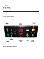
AQUASEAL
?
AS60/80UV Pro Liquid Laminator
Owner’s
Operation
Manual
AS60/80UV Pro Liquid Laminator
TABLE OF CONTENTS
TABLE OF CONTENTS ....................................................................................................................... 2
INTRODUCTION.................................................................................................................................. 3
IMPORTANT SAFEGUARDS ............................................................................................................... 4
IMPORTANT SAFEGUARDS CONTINUED...................................................................................... 5
SAFETY FEATURES............................................................................................................................. 6
ELECTRICAL CABINET FEATURES.................................................................................................. 7
CONTROL PANELS.............................................................................................................................. 8
CONTROL PANELS (Continued).......................................................................................................... 9
CONTROL PANELS (Continued).......................................................................................................... 10
OVERVIEW OF OPERATING FEATURES........................................................................................ 11
LACQUER SUPPLY OPERATION....................................................................................................... 12
SET-UP AND OPERATION ................................................................................................................. 13
SHUT-DOWN OPERATION ................................................................................................................ 14
CLEANING THE COATING MACHINE............................................................................................. 15
MAINTAINING THE COATING MACHINE ...................................................................................... 16
UV LAMP OPERATION / MAINTENANCE ...................................................................................... 17
ROLLER SPEEDS AND COATING RESULTS ................................................................................... 18
ROLLER SPEEDS AND COATING RESULTS (continued)................................................................ 19
SPARE PARTS LIST............................................................................................................................... 20
TROUBLESHOOTING GUIDE............................................................................................................ 27
TECHNICAL SPECIFICATIONS (COATING SECTION ONLY)...................................................... 28
LIMITED WARRANTY.......................................................................................................................... 29
2
INTRODUCTION
Thank you for purchasing a Seal AS60/80 UV
Liquid Laminator. We have designed the Seal
AS60/80 UV Liquid laminator to give you years of
reliable service. As you become familiar with your
liquid laminator, you will appreciate the high quality
of its production and the excellence in its
engineering design.
By following the guidelines for proper care and use
of the SEAL AS60/80UV, you can depend on
many years of trouble-free profitability from your
investment.
Please read and fully understand the entire
manual before proceeding to use your
laminator.
CAUTION! Please pay attention to all shaded
passages. This information is vital to
preventing user injury and/or damage to the
unit. Failure to follow this information could
void the user’s warranties and transfer all safety
obligations to the user.
STATEMENT OF INTENDED USE
The SEAL AS60/80UV laminator is intended for
use with medium and large format graphic output.
Graphics can vary in widths from 100mm –
2032mm (4” – 80”). Mounted graphics can be up
to 76mm (3 in.) thick. The SEAL AS60/80UV
liquid laminator is intended for use with Seal AS
lacquer only. Use of other manufacturer’s lacquers
may damage the machine and will void any
warranty.
WARNING! This laminator is designed for
liquid laminating. Any use other than the
intended may cause damage to the laminator
or physical harm to the user.
WARNING! Any unauthorized changes or
modifications to this unit without our prior
written approval will void the user’s warranty
and will transfer health and safety obligations
to the user.
LIABILITY STATEMENT
The details given in this manual are based on the
most recent information available to us. They may
be subject to change in the future. We retain the
right to make changes to the construction or the
design of our products without accepting any
responsibility for modifying earlier versions
previously delivered.
3
IMPORTANT SAFEGUARDS
SAFETY INSTRUCTIONS
IMPORTANT! When using any equipment,
always follow the manufacturer’s instructions
for safe operation.
?? Make sure machine is connected to the proper
power source.
manufacturers recommendations when
handling chemicals.
To obtain MSDS Sheets for SEAL AS60/80UV
Products, please call Seal at 31 572 346 000.
?? Comply with all safety warning signs, labels,
and instructions.
?? Familiarize yourself with the layout of the
Control Panel, and with the operation of the
lacquer delivery system.
SAFETY WARNINGS
?? Operators should be trained on the proper use
of the machine and all safety procedures.
R OTATING PARTS: R ISK OF INJURY
?? Provide ventilation, eye protection, clean towels
and rubber gloves for use during cleanup.
?? It is advisable to wear eye protection when
filling/emptying lacquer tank. Always provide
an approved emergency eyewash station
adjacent to the machine.
?? In case of skin contact with uncured lacquer,
use soap and water to clean (do not use
solvents to remove lacquer from the skin—
solvents help lacquer to penetrate the skin).
Repeated skin contact will result in a skin rash-uncured UV liquid is a skin irritant. Cured UV
liquid does not irritate the skin. (1 box of latex
gloves has been shipped with the machine.)
?? Review MSDS prior to working with UV
material.
WARNING! Ensure a clean well-ventilated
work area. Avoid direct skin contact with
uncured UV lacquer. Wear rubber gloves and
UV blocking safety glasses. Failure to avoid
contact with hot surfaces may cause burns. Do
not look directly at the UV light source.
CAUTION! When handling any chemical
products, read the manufacturers’ container
labels and the Material Safety Data Sheets
(MSDS) for important health, safety, and
environmental information. Always observe
4
CAUTION! Failure to use caution near
rotating rollers could result in physical injury.
Be careful that items such as loose clothing,
long hair and jewelry do not become entangled
in rotating parts.
Beware of pinch points. Never operate machine
with protective covers removed. Keep hands
outside of machine when feeding materials into the
machine. Never reach into machine when rollers
are moving.
E LECTRICAL P ARTS – D ANGER OF
BEING INJURED BY ELECTRICITY
WARNING! Do not open electrcal cabinet
doors because of the risk of being injured by
voltage. Only authorized maintenance and
service technicians or safety personnel should
have access to the electrical cabinet for
mechanical /electrical upkeep or repair.
IMPORTANT! Do not place heavy objects on
the power supply cord.
IMPORTANT SAFEGUARDS CONTINUED
PREVENTATIVE MEASURES:
Do not feed objects such as staples, paper clips and
rough or abrasive materials through the laminating
rollers.
Keep all objects, such as tools, rulers, pens, markers
or knives away from the roller opening. Refrain
from leaving such items on the tables to prevent
them from accidentally being fed into the rollers.
IMPORTANT! NEVER cut or slice directly on
the EPDM covered roller as any cuts, dents or
gouges will destroy it and adversely affect the
output. ALWAYS use cutters with enclosed
blades to prevent cutting the roller and to avoid
extensive replacement costs.
exposure to UV light will result in a condition
colloquially known as “welders flash”--the eyes will
itch and burn or feel sandy for a period of time.
This condition should be avoided. Permanent eye
damage can result. (2 sets of tinted eyeglasses have
been shipped with the machine.)
SERVICING AND REPLACEMENT PARTS
Service and maintenance must be performed fully
in accordance with the instructions. Servicing by
any unauthorized technician voids the warranty.
The service technician must use replacement parts
specified by Seal.
UV Light Safety:
Service Technicians must perform safety
checks after completing any service or repairs
to the laminator.
Never look directly at the UV curing lamps. If
working for extended periods at the machine wear
UV blocking glasses (clear or tinted). Over
WARNING! If your laminator does not operate
correctly, contact Technical Service
immediately.
5
SAFETY FEATURES
The Seal AS 60/80 UV Liquid Laminator is
designed with safety and protective devices with the
user’s safety of utmost consideration. However,
following safe operating guidelines is still the
responsibility of the operator.
H AND-OPERATED E MERGENCY STOP B UTTONS
Six Emergency Stop buttons are located on the
front and sides of the roller coating machine for
easy access. These E-Stops are interlocked with the
UV drying unit’s emergency stop system. If either
switch is pressed, they immediately cease the
operation of both machines. Use these only in the
case of an emergency or you may damage an image
during a process.
NOTE! Whenever there is an emergency shut
down you must wait 15 minutes before
restarting the UV section to allow the UV lamp
to cool down.
NOTE: Once pressed, these buttons lock and
must be turned clockwise to reset.
To restart machine follow this procedure:
a) Reset Emergency Stop Mushroom Switch
by turning the mushroom until it pops up.
b) On the Coater press the “SR Set” push
button. Turn on the pump, motors, and
scraper.
c) On the Dryer, start the blower and the
transport.
d) After fifteen minutes the UV lamps can be
turned on.
6
L OCKING C ABINETS
The cabinets that house the inner workings of the
laminator include locks that maintenance or safety
personnel can open only with the supplied keys.
WARNING! Use of the inside of the cabinets
for storage may cause possible personal injury
and/or damage to the inner workings and will
void the warranty.
MAIN SWITCH WITH DOOR INTERLOCK
Located on the cabinet, it automatically shuts the
laminator power off when the door interlock switch
is turned to the OFF position.
WARNING! For any servicing, ALWAYS turn
the door interlock switch to the OFF position
before opening the side cabinets.
ELECTRICAL CABINET FEATURES
Electrical Cabinet
1. Emergency Stop Buttons (2)
?? Located on the top of both side cabinets they
immediately cease the operation of both machines.
2. Control panel system
?? Turns On/Off the liquid laminator and provides
independent control of speed, roller direction ,
roller height, pump and read-out of UV lamp value.
The speed control is independent of the UV dryer
unit’s speed.
3. Override Key Switch
?? Used when cleaning up the UV Coating unit. When
the lacquer valve is in the cleaning position, the
pump cannot be turned on from the control panel.
To activate the lacquer pump, press the ON/OFF
pushbutton and turn on the cleaning override
switch.
4. Main Switch with Door Interlock
?? Turning the Main switch to the Off position shuts
down the operation of the machine and disengages
the door interlock.
5. Power and Interface Plugs
?? Power supply Plug and UV Drying Unit Interface
Plug.
7
CONTROL PANELS
Coating Machine Electrical Controls:
8
CONTROL PANELS (Continued)
S PEED CONTROL
?? The speed control sets the speed of the roller
motor.
?? NOTE: The speed control for the roller
coating machine is independent of the speed
of the UV dryer machine.
??
ON/OFF P USHBUTTON
?? The On/Off Pushbutton controls the safety
relay that supplies power to the machine.
??
R OLLER MOTOR CONTROL—IDLE, RUN,
R EVERSE MODES
?? There are three operating modes for the roller
motor as follows:
?? IDLE mode: the roller motor turns forward at
a slow speed.
?? RUN mode: the roller motor turns forward at
a speed determined by the motor speed
control knob setting.
?? REVERSE mode: the motor turns backwards
at a fixed, slow speed.
?? Press RUN/IDLE: the machine comes up in
IDLE mode.
?? Press RUN/IDLE again: the machine comes
up in RUN mode.
?? Press RUN/IDLE again : the machine comes
up in IDLE mode.
?? Press REVERSE : the machine stops and
then comes up in reverse mode—the IDLE
indicator light will blink to indicate reverse.
?? Press REVERSE again : the machine comes
up in IDLE mode.
L ACQUER SUPPLY—PUMP
?? Press PUMP pushbutton : if the lacquer valve
is in the return position the pump will start
and the PUMP LED will come on.
?? Press PUMP again: the lacquer pump will turn
off.
?? Press PUMP: if the lacquer valve is in the
clean up position the PUMP LED will blink
several times and then turn off; the pump will
not turn on.
MIDDLE C OATING R OLLER MOVEMENT—U P ,
DOWN
?? When the machine is turned on, one of the
coating roller position lights will illuminate.
?? Press the UP or DOWN button to move to
the next position.
S CRAPER ADJUSTMENT .
?? The scraper cleans the bottom roller. When
running un-mounted materials scraper
adjustment is critical. There should be no lacquer
streaks on the backs of coated materials. The
scraper pressure is controlled by air pressure.
The coating roller should be in the zero
(down) position and the lacquer pump should
be on. Scraper adjustment is controlled by an
air valve labeled “Scraper Pressure”.
Generally the scraper is run at 50-100 psi.
When cleaning the machine with alcohol,
scraper pressure should be reduced to 10-15
psi. Never engage the scraper with the bottom
roller dry, ie always coat both rollers with
lacquer before engaging the scraper.
9
??
CONTROL PANELS (Continued)
UV Dryer Electrical Controls:
UV L AMP AND CONVEYOR CONTROLS
For details consult the UV curing machine manual.
10
OVERVIEW OF OPERATING FEATURES.
R OLLER ASSEMBLY
The roller assembly is the heart of the coating
machine. It uses a three-roller design.
The top roller supplies lacquer to the coating roller.
The middle coating roller applies the lacquer to the
face of the image being coated.
The bottom roller presses the back of the image
material ensuring an even coating pressure.
A maximum amount of lacquer evenly distributed
across the whole roller provides the best coating
result.
F EEDING MATERIALS THROUGH THE COATING
R OLLER
Materials are fed face up through the roller
assembly under the middle coating roller.
R OLLER ADJUSTMENTS.
There are two roller adjustments. Pinch roller
pressure adjustment and coating roller elevation
adjustment. The pinch roller is directly in front of
the coating roller.
The pinch roller pressure is controlled by an air
pressure valve labeled “Pinch Roll Pressure”.
50 psi is the normal setting. For thicker coating
reduce the pressure. For thinner coating increase
the pressure.
Roller elevation is controlled by a hand wheel
adjustment. The digital readout
is calibrated in thousandths of an inch. The white
digits represent whole numbers, the three yellow
digits represent three digits to the right of a decimal
point, i.e. 0.001” to 0.999”.
Follow these steps to adjust the rollers for your
mounted materials: (1) prepare a 6”x20” piece of
your mounting board, (2) raise the rollers higher
than the thickness of your board, and (3) with the
rollers stopped, insert your board and lower the
rollers until there is a slight pressure – check for the
same pressure, right and left.
11
LACQUER SUPPLY OPERATION
D UAL LACQUER AND CLEANING SUPPLY.
There are three pumps and three drain valves. Two pumps are dedicated to two types of coating liquid
(“L1” and “L2”). The third pump is for the propyl alcohol cleaning liquid. Before starting the pump
always check the three drain valves--two should be closed, one should be open. The open valve must
match the pump selected on the pump selector switch. Because the coating liquid will not cure unless
it is exposed to UV light, the machine does not have to be cleaned daily. Once a week is sufficient. The
“L1” drain and the “L2” drain have in-line filters to filter the lacquer returning to the “L1” and “L2”
reservoirs. Depending on the type of material being coated, these filters will need to be cleaned on a
periodic basis.
12
S E T-UP AND OPERATION
S TARTING AND R UNNING THE MACHINE
First start the UV Dryer
Second allow the UV Lamp to warm up
Third start the Coating Machine
P ERSONAL PROTECTION
WARNING! Always wear rubber gloves
and glasses when handling UV lacquers. If
you get lacquer on your skin, wash it off
immediately with soap and water. Do not
use solvents to remove lacquer from the
skin—solvents help lacquer to penetrate the
skin.
S TART UP :
A. Check lacquer supply. If you need to add to
the reservoir do so now. Also check the propyl
alcohol cleaning reservoir. If you are running
linty materials (canvas) you will need to open and
clean the return filter for whichever coating
lacquer you have been using. The filter screen
can be cleaned by flushing with propyl alcohol.
Avoid skin contact with uncured UV lacquer, if
you get it on your skin wash it off immediately
with soap and water. Never use alcohol to
remove lacquer from the skin.
B. Look under the feed table and inspect the
scraper for cleanliness. If you are running clean
materials you may never have to clean the
scraper, if you are running canvas (linty
materials) you may need to clean the scraper on a
regular basis.
C. Turn on the Main Switches. Press the SR Set
button on the coater front panel. On the UV
Dryer panel, turn the Off/On/Lamp switch to
On. The belt motor and the exhaust blower will
come on. Turn the Off/On/Lamp switch to the
momentary Lamp position; the UV lamp will
start to warm up (the UV Lamp High/Low switch
should be in High position , “200”). You can
adjust the speed of the machine by turning the
Speed Knob. Set the belt speed to 50 FPM.
D. Next we will set the roller gap. Turn the hand
wheel clockwise until the digital display reads
“000125”. The rollers should be separated with
an eighth inch gap. (Caution: Wear eye
protection if the UV lamp is lit.)
E. Check the pinch roller pressure setting-normally 50 psi. Press the green Top Roll Motor
push button. Press the Motor ON keypad and set
the roller speed knob to 70 FPM.
F. Select L1 or L2 on the Pump Selector
Switch, open the 1st or 2nd drain handle (the W
drain handle should be closed). Turn on the green
Pump ON push button and adjust the pump
speed to one to two strokes per second. Pump
pressure should be 20-60 psi. Stroke rate is
controlled by adjusting the pump valve.
G. Start bottom roll motor. Press green Bottom
Roll Motor push button.
Press Motor ON
keypad.
Adjust roller speed knob to 50
FPM.
H. Now we will bring the rollers together. Turn
the hand wheel counter clockwise until the digital
indicator reads all zeros. The rollers should be
touching with no light showing.
(Caution: Wear eye protection if the UV lamp is
lit.)
I. Finally activate the scraper. Press the green
Scraper ON push button. The scraper pressure
should be 50-100 psi.
13
S H U T -D O W N O P E R A T I O N
S HUT DOWN:
alcohol. Stray actinic light will cause the
lacquer to cure in the machine.
A. Turn off UV lamp. Allow the UV dryer to
cool down for five minutes before turning off the
belt motor and exhaust blower.
IMPORTANT! Regardless of the
environment the machine should be
cleaned once a week.
B. Press the red Lacquer Pump push button.
Close the pump valve.
C. If the coating roller is elevated, carefully
return it to zero position.
In this position excess lacquer on the top rollers
will be transferred to the bottom roller and
scraped into the pan and returned to the reservoir.
After running until the excess lacquer is gone,
raise the top rollers off of the bottom roller.
(Leaving the rollers in contact with each other
can cause the rubber roller to be “dented” along
the pressure line. Many times the “dent” can be
removed by running the roller with pressure
applied--but to avoid the expense of replacing the
coating roller always remove pressure on the
rubber coating roller when you shut the machine
down.)
D. Press the red Top Roll Motor push button.
Press the red Bottom Roll Motor push button.
??
WARNING! Always wear rubber gloves
and glasses when handling UV lacquers. If
you get lacquer on your skin, wash it off
immediately with soap and water. Do not
use solvents to remove lacquer from the
skin—solvents help lacquer to penetrate the
skin.
??
?? If the machine is installed in a dirty or light
environment – you must thoroughly clean!
?? If the machine is exposed to direct daylight or if
your overhead lighting is actinic (contains UV)
you must clean the machine with isopropyl
14
Press the red Bottom Roll Scraper push button.
CLEANING THE COATING MACHINE
WARNING! Always wear rubber gloves and
glasses when handling UV lacquers. If you get
lacquer on your skin, wash it off immediately
with soap and water. Do not use solvents to
remove lacquer from the skin—solvents help
lacquer to penetrate the skin. When working
with alcohol avoid skin contact and provide
adequate ventilation.
D ISPOSAL OF C HEMICALS
?? Use disposal methods in accordance with local
regulations when disposing the alcohol/lacquer
mixture.
C LEANING CYCLE:
The cleaning cycle is similar to a standard Start
Up. Wash is selected on the pump selector
switch and the “W” drain handle is turned to the
open position. With the rollers in contact, run the
machine for ten or fifteen minutes. Top and
bottom rollers should be set to the same FPM
setting. The scraper pressure should be in the 1015 psi range.
If you are cleaning the machine to change to a
new lacquer that may be incompatible with the
old lacquer, after the first cleaning cycle replace
the alcohol and repeat the cycle.
C LEANING THE T RANSFER BELTS :
(The rollers should be separated with the bottom
roller running.) The transfer belts can be cleaned
“automatically” by filling the transfer belt tray
with alcohol. To do this, close the drain valve on
the tray (in the window under the feed table in the
center of the machine). Start the wash pump.
(Pump pressure should be 20 psi for alcohol.)
There are two valves exiting the wash pump, one
pointed at the top rollers, the other connected to
tubing that runs into the transfer belt tray.
Partially open the transfer belt tray valve (leave
the roller valve closed). When the transfer belts
are wetted with alcohol turn off the valve and turn
off the pump. Allow the machine to cycle for a
few minutes. Open the transfer tray drain valve to
drain the alcohol and leave it open.
15
MAINTAINING THE COATING MACHINE
P UMP MAINTENANCE.
There are three pneumatic pumps. Two for
lacquer, one for alcohol wash. The pumps are
identical. The pumps clip into brackets and are
completely removable.
16
Lacquer viscosity can affect pump performance.
Lacquer viscosity is measured in Zahn seconds
using a #2 Zahn cup (supplied with machine).
Typically the lacquer will measure between 30
to 60 Zahn seconds.
UV LAMP OPERATION / M AINTENANCE
UV L AMP OPERATION AND MAINTENANCE.
The medium pressure UV lamps have a
characteristic start up. The quartz glass bulbs are
filled with argon and little droplets of mercury.
When high voltage is first applied to the lamp the
argon lights and glows. It is the glowing argon
that heats the bulb and evaporates the mercury. It
is the mercury vapor arc that produces UV
radiation. Because of this evaporation cycle,
when the lamp is turned off, wait 15 minutes
before restarting.
Repeated starts shorten the life of the UV bulb. It
is customary to light the bulb once each day.
Instead of turning off the lamp it is placed in
stand-by mode in between coating runs. There is
a stand-by position (Low) on the UV Lamp
High-Low selector switch.
Over time the UV output of the lamp will weaken
and the lamp will have to be replaced. There is
an hour meter wired into the lamp circuit to track
the total on-time of the lamp.
T URN OFF THE MAIN SWITCH.
To replace the lamp, open the lamp housing, lift
the reflector and set it to the side. The lamp
terminals can then be disconnected on each end
and removed. Caution: wear cotton gloves when
handling quartz lamps. Oil from the fingers will
mark the quartz when the lamp is heated and
cause failure. Wash the lamp surface with clean
propyl alcohol prior to starting for the first time.
17
ROLLER SPEEDS AND COATING RESULTS
R OLLER S PEEDS AND C OATING R ESULTS.
Top and bottom roller speeds are independently
controlled allowing a great deal of flexibility in
coating results.
There are basically two types of materials.
Thick materials which require the rollers to be
set with a gap (material thickness minus 0.012”
[0.3mm]) and thin materials which are run
through closed rollers with the bottom roller
scraper engaged.
R OLLER SPEEDS WITH THICK MATERIALS.
The thickness of the coating can be controlled
by varying the ratio of top to bottom roller
speeds. The faster the top roller, the thicker the
coating. The coating is even across the entire
width of the machine. Thickness is both
uniform and controllable. For example, paper
based materials that are absorbent (and in other
coaters required two or more passes to coat) can
be coated in a single pass. The only limit for
thick substrates is the uniformity of thickness of
the substrate. Substrates that are thick in the
middle and thin on the edges require very
careful roller setting--and if there is too much of
a center to edge difference the edges will not
coat. Substrates with dings or dents will not
coat in the dented area. Coating texture is
controlled by the overall speed of the machine.
Running in a slower range will produce
smoother coating texture.
18
SUBSTRATES :
Styrene: Stable product coats evenly.
Foam Board: Coats evenly but falls off on
edges--edges thinner than center.
Gator Board: Coats evenly.
Sintra: Coats evenly--material slightly thicker in
the middle.
Coreplast: Easy to coat.
Alumalite: Easy to coat.
Sample set up speeds for thick substrates: 100
top roller / 50 bottom roller / 55 dryer.
For smoother texture: 60 top roller/ 30 bottom
roller / 35 dryer.
Thin substrates require more attention. First
there is the scraper. The scraper needs to be
properly applied and adjusted so that the backs
of coated materials do not pick up UV lacquer.
Thin materials can adhere to the coating roller-thin materials that have an affinity for wrapping
around the coating roller will need a leader, or
will need to be taped to a board, or will need to
be operated using a roll feed and take up system.
Materials that have enough weight (stiffness)
will coat without problems. Decal material and
cyclone paper fall into this category. Materials
that are very light tend to ride up the coating
roller on the exit side of the nip. Light weight
banner material exhibits this property. Where it
rides up and separates from the roller can result
in a rough texture to the coating. To properly
coat light
ROLLER SPEEDS AND COATING RESULTS (continued)
weight materials tension must be maintained on
the exit side of the nip. This can be
accomplished by use of a long leader (long
enough to extend through the dryer), or through
use of a roll feed and take up system.
MATERIALS:
(Run with the aid of the 9 nozzle air separator
system.)
Decal material (adhesive backed).
Cyclone paper (coated paper for ink jet
printers).
Sample set up speeds for decal paper: 30 top
roller / 40 bottom roller / 45 dryer. In this
situation running the top roller slower than the
bottom roller discourages wrapping.
19
SPARE PARTS LIST
Part Number
Description
AP-1
3034Lite X 74
AP-28
Coupling
Ap-2
Exit Bar
AP-29
Tubing connector
AP-3
ExitBarBracket
AP-30
Ball Valve
AP-4
1515 x 9.00”
AP-31
BTIinletDeflector
AP-5
80204303 (angle)
AP-32
BTIDClamp
AP-6
80203299 (hammer nut)
AP-7
Half inch nut
AP-8
5/16 nut
AP-9
5/16 washer
AP-10
Pulleys
AP-11
Washers
AP-12
0.250” x 72” SS round stock
AP-13
ARTroller
AP-14
ARTrollerEndCap
AP-15
ARTrollerEndShafts
AP-16
40BS11 Sprocket
AP-17
40BS36MOD Sprocket
AP-18
#40 Chain
AP-19
#40 Connector
AP-20
Belts
AP-21
Aluminum Belt Connectors
AP-22
BearingsMOD
AP-23
80204301MOD
AP-24
Belt Tray Assembly
AP-25
Belt Tray
AP-26
Spacers
AP-27
Endplate for Belt Tray
20
Blow Off System
Part Number
Description
BOS-1
3030 X 58
BOS-2
BlowBarBracket
BOS-3
1/4” X 1/8mnpt
BOS-4
High Pressure Air Nozzles
BOS-5
BowBarBracketSpacer
BOS-6
PressureCap
BOS-7
1”npt street el
BOS-8
1”npt X 1-1/2” nipple
BOS-9
10 Cv solenoid valve, 24 vdc
BOS-10
1”npt street el
BOS-11
1”npt X 7” pipe
BOS-12
1”npt 90 Deg El
BOS-13
1”npt X 4” nipple
BOS-14
1”npt 90 Deg El
BOS-15
1”npt X 1-1/2” nipple
BOS-16
Air Regulator
BOS-16.1
Union
BOS-17
1”npt X 1 -1/2” nipple
CA-8
Gearbelt18Pulley
BOS-18
1”fnpt X 1-1/2”fnpt coupler
CA-9
Bushing
BOS-19
Bronze Hose Adapter
CA-10
Gearbelt
CA-11
NordMotorSpacers
BOS-20
15' of 1-1/2” EPDM Rubber
Hose 150psi
CA-12
GearMotorMount
BOS-21
Bronze Hose Adapter 90 Deg
El
CA-13
1530X19p5Drilled
BOS-22
Air receiver
CA-14
1X6X4PRSlider
BOS-23
Photosensor
CA-15
Unibearing Pad
BOS-24
PhotosensBracket
CA-16
1X6X4PRSideblock
BOS-25
8020 Fractional Section 1 page
CA-17
1545plate
CA-18
1545X73.875
BOS-26
8020 Fractional Section 4 page
127
CA-19
LacquerValveBracket
8020 Fractional Section 1 page
59
CA-19.1
Natural Polypro Hose Barbs
BOS-27
PD-9
22272
BOS-28
ExitFinger
CA-19.3
Spacers
BOS-29
8020 Fractional Section 4 page
127
CA-19.4
M6 X 1 X 55
CA-20
1530X6
BOS-30
1", HI PSI, Gauge Regulator,
Large
CA-21
Unibearing Pad
BOS-31
Worm-Drive Hose Clamp
CA-22
Unibearing Pad
CA-23
91618allthread10p5
CA-24
CRBaseplate
CA-25
3030X86
CA-26
5X66 Roller
CA-27
Air Cylinder
Carriage Assembly
Part Number
Description
CA-1
Rubber Roller
CA-2
Core
CA-3
Gearbelt22Pulley
CA-4
Bushing
CA-5
CA-6
Pillow Block Bearings
CA-7
NordGearMotor
21
Lifter Parts
Part Number
Description
LP-1
Screwjack
LP-2
Miterbox
LP-3
3/8" Minature Keyless Shaft
Mount
LP-4
ScrewjackCouplerLeft
LP-5
MiterBoxSpacer
LP-6
MiterCoupler66
LP-7
5913MiterCouplerBearing
LP-8
MiterCouplerBearingBracket
LP-9
ScrewjackCouplerRight
LP-10
HandWheelShaft
LP-11
Bearing
LP-12
HWBearingSpacer
LP-13
Tejax Digital Counter
LP-14
Hand Wheel
Main Frame
Part Number
Description
MF-1
Top cross beam
MF-2
Internal Hanger Brackets
MF-3
91618allthread30p5
MF-4
Carriage guide rails
MF-4.1
91618allthread10p5
MF-5
SJBaseplate
MF-6
SJBaseplateRIGHT
MF-7
RightAngleMotorMount
22
MF-8
MotorSpacers
MF-9
RightAngleMotor
MF-10
LovejoyCoupling
MF-11
LovejoyCoupling
MF-12
LovejoyCoupling Spider
MF-13
Pillow Block Bearing
MF-14
6x66Roller
MF-15
HangerPostBracket
MF-16
Main columns
MF-17
Bottom cross brace
MF-18
LevelFootBlock
MF-19
Foot
MF-20
Top front and back rails
MF-21
End columns
MF-22
End Bottom Rails
MF-23
Middle front rail
MF-24
3030X6
MF-25
Bottom front and back rails
MF-26
Outside cross corner braces
and top middle braces
MF-27
Exit Stabilizer Bar
MF-28
Spacer
MF-29
4 x 4 corner brace
MF-30
2v x 2v corner bracket
MF-31
2h x 2h corner bracket
Pumps and Drains
Part Number
Description
PD-1
Air Solenoid for Pump
PD-1.1
Tube Fitting Swivel Tee
PD-1.2
Tube Fitting Male Straight
Adapter
PD-2
PumpAirSolBrkt
PD-3
Pump Valve Panel
PD-4
Air Regulator Valve
PD-4.1
¼ Nptf X 5/16 Swivel EL
PD-5
Air Pressure Gage
PD-5.1
¼ FPT Brass Coupling
PD-5.2
¼ Nptf X 5/16 Push Tee
PD-5.3
¼ Nptf X 5/16 Straight Male
PD-6
Pumps
PD-7
Double Pump Panel
PD-21
1”npt SS 1-1/2” nipple
PD-22
1”npt SS union
PD-23
1”npt SS 1-1/2” nipple
PD-24
1”npt SS ball valve
PD-25
1”npt SS 24” nipple
PD-26
1”fnpt Polypropylene screen
filters
PD-27
1”npt SS 1-1/2” nipple
PD-28
1”npt SS 90 deg el
PD-29
1”npt SS 1-1/2” nipple, thd
one side
PD-30
1-39/64"OD, Coupling, 100
PSI, 1-5/8"L
PD-31
1" Pipe SizeX4" L, 11/16"
Thread L
PD-32
1" Pipe, 1-1/2" L, 11/16"
Thread L
1" Pipe, 1.315" OD, 24" L,
11/16" Thread L
PD-8
Single Pump Panel
PD-33
PD-9
Polypropylene Ball Valves
PD-34
DrainPipeSupport
PD-35
DrainPipeSupportBracket
PD-10
1/4”npt x 3/8” barb,
polypropylene
PD-36
Carboy
PD-11
1”npt to 3/4”npt SS reducer
bushing
PD-37
Suction Strainer
PD-12
3/4”npt SS 1-3/8” nipple
PD-38
SS Hose Straigtener Tube
PD-13
3/4”npt SS union
PD-39
3/8Plastic hose barb x ½ mpt
PD-14
3/4”npt SS 1-3/8” nipple
PD-40
5/8Brass hose barb x ¾ mpt
PD-15
3/4”npt SS ball valve
PD-41
7/32" To 5/8" Clamp Id
Range
PD-16
3/4”npt SS 24” nipple
PD-17
3/4”fnpt Polypropylene screen
filters
PD-18
3/4”npt SS 1-3/8” nipple
PD-19
3/4”npt SS 90 deg el
PD-20
3/4”npt SS 1-1/2” nipple, thd
one side
23
Scraper and Pneumatics
SP-29
¼ Nptf X 5/16 Swivel Tee
SP-30
Micro Mist Lube
Part Number
Description
SP-1
Drawing 1Right,1Left
SP-2
Scraper Air Cylinders
SP-3
ScraperCylinderBlock
SP-4
ScraperMountingBlock
SP-5
Air Cylinder
SP-6
3030 X 70.875
Part Number
Description
SP-7
ScraperBladeBowedBackerBar
S-1
CDPanAssembly.dwg
SP-8
BowBarBracket
S-2
CDPanside.dwg
SP-9
BowBarBracketSpacer
S-3
1PipeEL.dwg
SP-10
ScraperCover
S-4
Feed Table66.dwg
SP-11
Stiffener66
S-5
HingePanelandFrontDoor.dwg
SP-12
SolValveBracket
S-6
FeedTableClamp
Scraper Air Solenoid Valve
24VDC
S-7
Knob, three lobed
SP-13
SP-14
Connector and cord
S-8
FrontBottomPanel66.dwg
SP-15
Exhaust Port Flow Control
S-9
QuarterControlPanel.dwg
SP-16
Pinch Roller Air Cylinders
S-10
QuarterPanelLeftFront.dwg
S-11
QuarterPanel.dwg
SP-17
Drawing, 4KB93.pdf
S-12
TopBackPanel66.dwg
SP-18
Drawing
S-13
TopHalf66.dwg
SP-19
Pinch Roller Air Solenoid
Valve 24VDC
S-14
TopEnd23p375d3.dwg
SP-20
Connector and cord
S-15
TopEndCornerBrace.dwg
SP-21
Exhaust Port Flow Control
S-16
8End3dAssembly.dwg
SP-22
Nylon Tube
S-17
8EndCapBraces.dwg
SP-23
Air Filter and Oiler Plate
S-18
EndCapDoor.dwg
SP-24
Hanger bracket
SP-25
Air Line Filter
SP-26
Brass Street EL
SP-27
Hose Coupling
PD-4.1
¼ X 5/16 Swivel EL
24
Sheetmetal
Electrical Parts
EP-21
KEYPAD CABLE GS
SERIES 1M
EP-22
N1 SCRW CVR WALL MT
PULL
Part Number
Description
EP-1
Thin Finger Duct Grey 1 Pc.
EP-2
GS2 0.5 HP AC Drive 230V
EP-23
GROUNDING KIT REQD
FOR CSA
EP-3
GS2 1.0 HP AC Drive 230V
EP-24
Multiconductor Cable
EP-4
HCLR 10-AMP, 10-Fuses per
pack
EP-25
EP-5
HCLR 20-AMP, 10-Fuses per
pack
Liquid-Tight Flexible Steel
Conduit
EP-26
Liquid-Tight Metal Conduit
Fitting
EP-6
HCLR 25-AMP, 10-Fuses per
pack
EP-27
DIN Rail-Mount High-Amp
EP-7
RELAY24VAC 2PDT 12A
EP-28
E-Stop Safety Relay
EP-29
35 A 200V GBPC
EP-8
RELAY SOCKET 750-2C
SERIES
EP-30
Conn Recept/Cap 3POS
EP-31
Conn Plug 3POS
EP-9
FUSE HOLDER, 6/PK, CC
CLASS, 2 POLE
EP-32
Conn Plug 9POS
EP-10
DISCONNECT 40A
ROTARY
EP-33
Conn Recept/Cap 9POS
EP-34
Conn Plug 12POS
EP-11
DISCONNECT REMOTE
HANDLE
EP-35
Conn Recept/Cap 12POS
EP-36
Conn Plug 15POS
EP-12
DISCONNECT REMOTE
SHAFT
EP-37
Conn Recept/Cap 15POS
EP-13
22MM MET TWISTREL
MUSH
EP-38
Conn Pin 14-20AWG Tin
Crimp
EP-14
YELLOW E-STOP
LEGEND PLATE
EP-39
Conn Socket 14-20 AWG Tin
Crimp
EP-15
SEL SW. 3 POS
MAINTAINED
EP-40
Conn .25" Female Insulation
14-16 AWG
EP-16
LEGEND PLATE BLANK
BLACK
EP-41
Conn Wire Pin Term 10-12
AWG
EP-17
22MM IL FLSH PB24V RED
EP-18
22MM IL FLSH PB24V GRN
EP-19
18 A CONTACTOR 43MM
EP-20
SEL SW. 2 POS
MAINTAINED
25
Miscellaneous
Part Number
Description
RM-1
RM-2
RM-3
RM-4
RM-5
RM-6
RM-7
Hammer Nut
RM-8
RM-9
Hose Barbs
RM-10
Scraper
RM-11
Shipping Crate
Operator's Tools
Part Number
Description
OT-1
UVC Blocker Glasses
OT-2
Rubber Gloves
OT-3
Electronic Calipers
26
TROUBLESHOOTING GUIDE
Problem
Solution
The laminator will not turn on.
Confirm that the power cable is plugged into the mains wall outlet.
Confirm that the Main Power switch is pressed ON.
Confirm that the Emergency Stop buttons were not activated. Rotate
to reset.
Unplug the laminator and check the fuses inside the right cabinet.
Only authorized safety or maintenance personnel should do this.
Make sure the right side cabinet door is closed and the Door interlock
is in the ON position. Turning the door interlock to the OFF position
automatically shuts the laminator power off.
The motor will not run.
Turn the motor speed up.
Unplug the laminator and check the fuses. Only authorized safety or
maintenance personnel should do this.
TECHNICAL SERVICE
For technical assistance, please contact your Technical Service representative (see rear cover).
When calling for Technical Service please have the Laminator Serial Number (listed on the Identification
Plate) available. The Identification plate is located on the rear left side of the laminator.
27
TECHNICAL SPECIFICATIONS (COATING SECTION ONLY)
IMPORTANT! The following specifications are for the Coating section. Refer to the UV Curing
Unit Owners Manual for the Technical Specifications specific to that section.
MECHANICAL
*Dimensions (H x W x D)
60” uncrated
56” h x 40” w x 104” d (143cm x 102cm x 265cm)
80” uncrated
56” h x 40” w x 124” d (143cm x 102cm x 315cm)
60” crated
70” h x 52” w x 124” d (178cm x 133cm x 315cm)
80” crated
70” h x 52” w x 144” d (178cm x 133cm x 366cm)
60”
2000lbs. ( 908kg)
crated 60”
2404lbs. (1091kg)
*Dimensions (H x W x D)
*Net Weight
80”
crated 80”
2200lbs. (998kg)
2700lbs. (1225kg)
P ROCESS
Max. Working Width
60 / 80” ( 1500 / 2000 mm) maximum
Max. Material Thickness
3” ( 76 mm)
Variable Coating Speed
30 - 110fpm ( 9 – 34mpm)
Coating Thickness
.0003 - .0012” ( .007 - .030mm)
E LECTRICAL R EQUIREMENTS
Single phase version
208-230 VAC 50/60 Hz
ORDER C ODES
ACCUCURE™ 80 UV 220V 63316 includes
coater and dyer unit
ACCUCURE™ 80 UV 380V 63318 includes coater
and dryer unit
ACCUCURE™ 60 UV 220V 63315 includes
coater and dryer unit
ACCUCURE™ 60 UV 380V 63317 includes coater
and dryer unit
* NOTE: unit ships on pallet. Shipping crate required for water freight and some land. Call for crate part number and pricing.
Each Seal liquid laminator has a Serial Number Label located on the rear of the cabinet. This label indicates
the model type, the electrical requirements, and the laminator serial number (important for reference if any
servicing is required).
28
LIMITED WARRANTY
Seal warrants to the original consumer purchaser
that each new Seal AS60/80 UV Liquid Laminator,
which proves defective in materials or
workmanship within the applicable warranty
period, will be repaired or, at our option, replaced
without charge.
The applicable warranty shall be one year from date
of purchase with the exception of EPDM rollers
that will be six months from date of purchase.
"Original consumer purchaser" means the person
who first purchased the product covered by this
warranty other than for purpose of resale.
The warranty extends to and is enforceable by only
the original consumer purchaser, and only for the
period (during the applicable term), which the
product remains in the possession of the original
consumer purchaser. This warranty does not apply
if it is found that at any time the equipment has not
been used for its intended purpose.
All rights are reserved. No part of the document
may be photocopied, reproduced, or translated to
another language without the prior written consent
of Seal.
The information contained in this document is
subject to change without notice and should not be
construed as a commitment by Seal.
Seal assumes no responsibility for any errors that
may appear in this document. Nor does it make
expressed or implied warranty of any kind with
regard to this material, including, but not limited to,
the implied warranties of merchantability and
fitness for a particular purpose.
Seal shall not be liable for incidental or
consequential damages in connection with, or
arising out of the furnishing, performance, or use
of this document and the program material, which
it describes.
For more information regarding this warranty,
please contact your distributor.
WARNING! Any unauthorized changes or
modifications to this unit without our prior
written approval will void the user’s warranty
and will transfer health and safety obligations
to the user.
WARNING! Changes or modifications to this
unit not expressly approved by the party
responsible for compliance could void the
user's authority to operate the equipment
29
PROCESS SHEET
Substrate-__________________________
Coating-___________________________
Thickness of Coating Required -
Heavy
Medium
Top Roller Speed -_____________________
Bottom Roller Speed-__________________
Scraper Blade Pressure (PSI)-________________
Pinch Roller Pressure (PSI)-_________________
Roller Nip Height-_______________________
Dryer Conveyor Speed-__________________
Air Separator-
ON / OFF
Lamp Intensity (WPI) -
250
30
/
150
Light
S EAL CUSTOMER / T ECHNICAL S ERVICE
(For information and placing orders)
Tel.: 31 572 346 000
Fax: 31 572 346 001
Note: Seal recommends that your main power be installed by a licensed electrician in accordance with electrical codes in your area.
Specifications subject to change without notice.
SEAL Graphics Europe
Heesweg 16A
HJ Raalte, The Netherlands
Tel. ++31 572 346 000
Fax ++31 572 346 001
© 2007 Seal
Part #OMAS60_80UV -ENG Rev. A
(11/07)
31