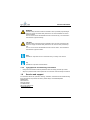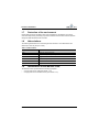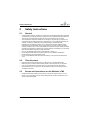
1
User Manual
Whistler LFMi
Lung Function Measurement instrument
0050.002.0020 - 06
Copyright
Copyright 2013 by MediSpirit BV.
All Rights Reserved.
No part of this document may be reproduced, stored in a retrieval system, or transmitted in
any form or by any means, electronic or mechanical, including photocopying and recording,
for any purpose, without the express written permission of MediSpirit BV.
The software described in this document (if applicable) is furnished under the Software
License Agreement. The software may be used or copied only in accordance with the terms
of the license.
Information in this document is subject to change without notice and does not represent a
commitment on the part of MediSpirit BV.
In no event shall MediSpirit BV be liable for incidental or consequential damages arising from
use of this document or the software (if applicable) and hardware described herein.
The original English text of this document will be legally binding and shall prevail in case of
any variance between the English text and a translation.
MediSpirit BV
De Pinckart 24
5670 AA Nuenen
The Netherlands
http://www.medispirit.eu
[email protected]
ii
0050.002.0020 - 06
Revision history
/i
Date
Definition
March 2012
Version 01
July 2012
Version 02
August 2012
Version 03
November 2012
Version 04
December 2012
Version 05
February 2013
Version 06
0050.002.0020 - 06
iii
Table of contents
1
2
General information
1.1
Intended users ................................................................................................... 1
1.2
Intended use of the Whistler LFMi ..................................................................... 1
1.3
About this document .......................................................................................... 1
1.4
Available technical documentation on the Whistler LFMi .................................. 2
1.5
Conventions....................................................................................................... 2
1.5.1 Pictograms ............................................................................................ 2
1.5.2 Typographical and authoring conventions ............................................ 3
1.6
Service and support........................................................................................... 3
1.7
Protection of the environment............................................................................ 4
1.8
Abbreviations ..................................................................................................... 4
1.9
Identification of the Whistler LFMi...................................................................... 4
1.9.1 Type plate on the cradle ....................................................................... 5
1.9.2 Type plate on the SOT/Rint-sensor ...................................................... 5
Safety instructions
2.1
3
4
5
This document ................................................................................................... 6
2.3
Decals and instructions on the Whistler LFMi.................................................... 6
2.3.1 Decals and instructions on the cradle ................................................... 7
2.3.2 Decals and instructions on the sensors ................................................ 7
2.4
Before you use the Whistler LFMi...................................................................... 8
2.5
When you use the Whistler LFMi....................................................................... 8
2.6
When you have used the Whistler LFMi ............................................................ 8
General description
3.1
Characteristics ................................................................................................... 9
3.2
Main components ............................................................................................ 10
3.2.1 Cradle and sensors ............................................................................. 11
3.2.2 Error indicator and battery status indicator ......................................... 12
3.2.3 Cradle ................................................................................................. 13
3.2.4 SOT/Rint-sensor ................................................................................. 14
3.2.5 Accessories required for the measurements....................................... 15
Preparations for use
4.1
Exchange the sensor ....................................................................................... 16
4.2
Charge the battery ........................................................................................... 18
4.3
Place the Bluetooth dongle.............................................................................. 18
Lung function measurements
5.1
iv
General .............................................................................................................. 6
2.2
Prepare the Whistler LFMi application ............................................................. 19
5.1.1 Log on ................................................................................................. 20
0050.002.0020 - 06
5.1.2
5.1.3
5.1.4
5.1.5
6
7
8
5.2
Start the Whistler LFMi..................................................................................... 28
5.2.1 Switch the Whistler LFMi ON............................................................... 28
5.2.2 Set up Bluetooth communication......................................................... 29
5.3
SOT-measurement........................................................................................... 30
5.3.1 SOT-measurement principle................................................................ 30
5.3.2 Use the face mask............................................................................... 31
5.3.3 SOT-measurement screen .................................................................. 32
5.3.4 SOT-result screen ............................................................................... 33
5.4
Rint-measurement............................................................................................ 35
5.4.1 Rint-measurement principle................................................................. 35
5.4.2 Use the bacterial filter.......................................................................... 37
5.4.3 Use the face mask............................................................................... 38
5.4.4 Rint-measurement screen ................................................................... 40
5.4.5 Rint-result screen ................................................................................ 41
Cleaning instructions
6.1
Preparation....................................................................................................... 43
6.2
Clean the outside of the Whistler LFMi ............................................................ 43
6.3
Inspect the manifold ......................................................................................... 44
6.4
Clean the filter adapter ..................................................................................... 44
6.5
Clean the inside of the sensor.......................................................................... 44
6.5.1 Decision tree........................................................................................ 45
6.5.2 Remove the end cap of the sensor...................................................... 46
6.5.3 Rinse the sensor with clean water....................................................... 46
6.5.4 Prepare the soap solution.................................................................... 46
6.5.5 Clean the sensor with a brush ............................................................. 47
6.5.6 Clean the sensor with the soap solution.............................................. 47
6.5.7 Disinfect the sensor with ethanol......................................................... 48
6.5.8 Remove the occlusion valve................................................................ 48
6.5.9 Dry the sensor ..................................................................................... 49
6.5.10 Install the occlusion valve.................................................................... 49
6.5.11 Check the sensor (final check) ............................................................ 51
Verification
7.1
General ............................................................................................................ 52
7.2
Preparation....................................................................................................... 52
7.3
Verification test................................................................................................. 53
Troubleshooting
8.1
9
Menu bar, Tool bar and Status bar...................................................... 21
Patient screen...................................................................................... 24
Measurement data screen................................................................... 25
Device information screen ................................................................... 27
Troubleshooting table....................................................................................... 55
Maintenance
0050.002.0020 - 06
v
9.1
10
General ............................................................................................................ 63
Technical specifications
10.1 Standards ........................................................................................................ 64
10.2 Dimensions and weight.................................................................................... 65
10.3 Environmental conditions................................................................................. 65
10.3.1 Operational ......................................................................................... 65
10.3.2 Storage and transport ......................................................................... 65
10.4 Cradle .............................................................................................................. 65
10.4.1 Battery................................................................................................. 65
10.4.2 Ultrasonic transducer .......................................................................... 66
10.4.3 Bluetooth chip ..................................................................................... 66
10.5 Sensors............................................................................................................ 66
10.5.1 SOT/Rint-sensor ................................................................................. 66
10.6 Accessories ..................................................................................................... 67
10.7 Spare parts ...................................................................................................... 68
10.8 Disposables ..................................................................................................... 68
11
Appendix
11.1 Conversion SI-units - imperial units ................................................................. 69
vi
0050.002.0020 - 06
General information
1
General information
1.1
Intended users
This document is exclusively intended for professional, qualified users of the Whistler Lung
Function Measurement instrument (Whistler LFMi). As a user you are either a trained medical
specialist on pulmonary diseases, a trained paediatrician, a trained general practitioner or a
trained medical assistant.
1.2
Intended use of the Whistler LFMi
The Whistler LFMi is a state-of-the-art lung function measurement instrument that has been
exclusively designed to measure, calculate and present lung function parameters in a hospital
environment (see chapter 3). The Whistler LFMi does not produce any diagnosis. Therefore,
the interpretation of the results of the measurements and the deduction of conclusions from
these results always remains the responsibility of the medical specialist. The medical
specialist has the ability to diagnose and prescribe medications or to do further medical
research.
1.3
About this document
With the help of this document, you will become familiar with the Whistler LFMi and its
features so that you are able to use, operate and clean the instrument in an efficient, hygienic
and safe manner.
Therefore, this document provides the following information:
• important safety aspects during use, operation and cleaning (see chapter 2)
• a description of the main components and the measurements (see chapter 3)
• preparations for use (see chapter 4)
• procedures for the lung function measurements (see chapter 5)
• periodic cleaning tasks (see chapter 6)
• verification procedures (see chapter 7)
• basic troubleshooting tips (see chapter 8)
• basic maintenance instructions (see chapter 9)
• technical specifications of the Whistler LFMi (see chapter 10)
Note
Before you use or operate the Whistler LFMi, make sure that you read and fully
understand the contents of this document. Strictly observe the instructions given.
0050.002.0020 - 06
1
General information
1.4
Available technical documentation on the Whistler
LFMi
The table below shows the available technical documentation on the Whistler LFMi, the
document ID numbers and the contents per document.
/i
Table 1.1 Technical documentation on the Whistler LFMi
Document name
Contents
Document ID
User manual Whistler LFMi
Operation, cleaning and
basic troubleshooting
0050.002.0020-xxa)
Software installation manual Whistler
LFMi
Installation and configura- 0050.002.0021-xxb)
tion of the Whistler LFMi
software
a. xx = version number
b. xx = version number
These documents have been prepared with great care, and in compliance with the relevant
regulations. The contents is based on our experience and latest knowledge. The information
in these documents is therefore valid and correct at the moment of release (the release date
is on the front cover of the document). However, changes and improvements may be made to
these documents at any time and without prior notice.
The source language of these documents is English. As a translation may be imprecise or
inaccurate, the original English text will be legally binding. The English text shall prevail in the
case of any difference between the source text and the translation.
Note
As we continuously improve and develop our products, it is not always possible to
provide a truthful picture of every single detail of the Whistler LFMi. The illustrations in these documents therefore always show a typical and standard Whistler
LFMi.
Optional features or extra accessories will be clearly marked, both in the text and
(if required) in the illustrations.
1.5
Conventions
The following conventions apply for this document.
1.5.1
Pictograms
The following pictograms are used in this document.
2
0050.002.0020 - 06
General information
WARNING
Identifies safety instructions that are intended to warn of possible physical danger.
Failure to comply with these safety instructions can result in fatalities or serious
personal injuries.
The icon in front of the alert identifies the nature of the warning. The exclamation
mark denotes a general warning.
CAUTION
Identifies safety instructions that are intended to warn of minor personal injuries.
Failure to comply with these safety instructions can result in minor personal injuries.
The icon in front of the alert identifies the nature of the caution. The exclamation
mark denotes a general caution.
Note
Identifies an important note or an instruction that you always must observe.
Tip
Identifies an important recommendation.
1.5.2
•
•
Typographical and authoring conventions
Listings and enumerations without prescribed order are always preceded by a bullet.
Steps in a procedure that must be performed in consecutive order are always numbered.
1.6
Service and support
For information about use, operation, cleaning, verification, maintenance and troubleshooting
that is beyond the scope of this document, please always contact MediSpirit BV:
MediSpirit BV
De Pinckart 24
5670 AA Nuenen
The Netherlands
http://www.medispirit.eu
[email protected]
0050.002.0020 - 06
3
General information
1.7
Protection of the environment
Please observe all local regulations and recommendations for the disposal, recycling or
environmentally friendly processing of parts and materials that have been used or replaced
during the tasks described in this document.
1.8
Abbreviations
The following abbreviations are used throughout this document. The abbreviations are
defined upon first use (except in a title).
/i
Table 1.2 Abbreviations
Abbreviation
Definition
ATS
American Thoracic Society
ERS
European Respiratory Society
LFMi
Lung Function Measurement instrument
Rint
Resistance by interruption
SN
Serial Number
SOT
Single Occlusion Technique
1.9
Identification of the Whistler LFMi
The Whistler LFMi is provided with the following type plates
• one type plate on the cradle (see section 1.9.1)
• one type plate on the SOT/Rint-sensor (see section 1.9.2)
4
0050.002.0020 - 06
General information
1.9.1
Type plate on the cradle
D
A
B
C
D
E
E
E
C
Product name
Cradle serial number
Manufacturer
Input voltage
Battery specifications
1.9.2
Type plate on the SOT/Rint-sensor
A
A
B
C
B
A
B
C
Product name
Sensor serial number
Manufacturer
0050.002.0020 - 06
5
Safety instructions
2
Safety instructions
2.1
General
•
•
•
•
•
•
•
The operational, cleaning, verification, maintenance and troubleshooting tasks described
in this document are strictly reserved to users who have completed the training sessions,
and who are acquainted with all safety instructions mentioned in this document.
The manufacturer accepts no liability for any damage or physical injury caused by noncompliance with the safety instructions in this document, or by carelessness during use,
cleaning, verification, maintenance and troubleshooting of the Whistler LFMi.
Depending on the working conditions in your specific environment, additional safety
instructions may be applicable. As the manufacturer has no direct control over these
working conditions, it is your sole responsibility to ensure that the local Health and Safety
regulations are adhered to. Please inform the manufacturer immediately if you have dealt
with unsafe situations that have not been described.
Only use the Whistler LFMi for the purpose defined in section 1.2.
Do not sterilize the Whistler LFMi. The instrument is not suitable for sterilization.
Never modify any part of the Whistler LFMi.
Do not use the Whistler LFMi when parts are missing or when technical malfunctions
occur.
2.2
•
•
•
•
Read this document thoroughly before you perform any of the tasks described.
Make sure that you always have the latest version of this document at your disposal.
Carry out the procedures in the order given. Do not change the order of the steps.
Keep this document in a safe place, near the Whistler LFMi. This document must be
accessible at all times.
2.3
•
6
This document
Decals and instructions on the Whistler LFMi
Decals and instructions fitted on the cradle or on the sensors (see section 2.3.1 and
section 2.3.2, respectively) are part of the safety features provided. These items must
remain present and legible.
0050.002.0020 - 06
Safety instructions
2.3.1
Decals and instructions on the cradle
2.3.2
Decals and instructions on the sensors
0050.002.0020 - 06
7
Safety instructions
2.4
•
•
•
•
•
•
•
Make sure that unauthorised persons have no access to the working area.
Make sure that the working area meets all local requirements that are applicable for the
use of medical devices (lighting, ventilation, ambient temperature, relative humidity,
hygiene, etc.).
Check the condition of the Whistler LFMi. Check that the sensor has been cleaned and
stored properly. Do not use the instrument when the interior of the sensor is humid.
Check the instrument on broken parts. Do not use the instrument when a sensor has
fallen on the ground. Check that there are no small objects inside the flow sensor.
Make sure that the Whistler LFMi battery is charged.
Only use a Whistler LFMi that has been cleaned according to the instructions in chapter
6.
Only use the Whistler LFMi on patients with a normal anatomy.
2.5
•
•
•
•
•
•
•
•
8
When you use the Whistler LFMi
Stay alert and watch what you are doing. Use common sense. Do not operate the
Whistler LFMi when you are tired or have been taking alcohol, medicine or drugs. Do not
smoke.
For each patient always use a new disposable face mask or a new disposable bacterial
filter.
For each measurement use the dedicated and recommended types of face masks and
bacterial filters.
Use the appropriate sensor for the measurement. When you use the SOT/Rint-sensor for
a specific measurement, instruct your patient to breathe normally. A powerful intake of
breath can cause the occlusion valve to close.
During the measurements always check that the patient can breathe freely. If not, remove
the Whistler LFMi from the patient.
During the measurements, disconnect the USB cable from the Whistler LFMi.
2.6
•
Before you use the Whistler LFMi
When you have used the Whistler LFMi
Thoroughly clean the Whistler LFMi in compliance with the procedures that apply in your
working environment and according to the guidelines in chapter 6.
Do not sterilize the instrument.
Store the Whistler LFMi in its case, in a clean and dry environment, out of reach of
unauthorised persons. See section 10.3.2 for the recommended storage conditions.
0050.002.0020 - 06
General description
3
General description
3.1
Characteristics
The Whistler LFMi is a handheld lung function measurement instrument that is used for
different types of lung function measurements for patients of all ages.
Note
The Whistler LFMi measures, calculates and presents lung function parameters,
but does not give any diagnosis. The interpretation of the results of the measurements and the deduction of conclusions from these results always remains the
responsibility of the medical specialist.
0050.002.0020 - 06
9
General description
3.2
Main components
A complete Whistler LFMi configuration consists of the components shown in the figure
below.
A
B
C
D
E
A
B
C
D
E
F
G
F
G
Whistler LFMi (see section 3.2.1 and section 3.2.3)
Exchangeable sensor (see section 3.2.4)
Accessories required for the measurements (see section 3.2.5)
Battery charger (with USB cable)
Bluetooth dongle
User manual
CD-Rom containing the User manual, the Software installation manual Whistler LFMi and
the software of the Whistler LFMi
Note
Some battery chargers have an integrated USB cable.
10
0050.002.0020 - 06
General description
3.2.1
Cradle and sensors
J
C
I
H
A
K
E
F
D
B
G
/i
Position
number
Definition
Description
A
Cradle
Contains the electronics, the battery and the occlusion
mechanism (see section 3.2.3).
B
SOT/Rint-sensor
Exchangeable sensor for both SOT- and Rint-measurements (see section 3.2.4).
C
ON/OFF-button
Pushbutton:
• ON: press 1x.
• OFF: keep pressed for 3 seconds.
D
Sensor release buttons
Buttons on both sides of the sensor to release the
sensor from the cradle.
E
USB port
USB port to charge the Whistler LFMi.
F
Reset switch
Enables to power down the Whistler LFMi by pressing
a small pointed object (e.g. a paperclip) into the hole.
0050.002.0020 - 06
11
General description
Position
number
Definition
Description
G
Connection for face
mask or bacterial filter
Connection end for the disposable face mask or the
disposable bacterial filter that is used for the measurements.
H
Error indicator
Red indicator that lights up when the valve blocks or
when the internal occlusion valve closes unintentionally (see section 3.2.2).
I
Battery status indicator
Green indicator that indicates the battery status (see
section 3.2.2):
• Slow blinking: charging (only when USB is connected)
• Flashing: the battery is almost empty
J
Running indicator
Indicator that lights up when the Whistler LFMi is configured for the selected measurement.
K
Internal buzzer
The internal buzzer generates an alarm to alert the
user that intervention may be required.
3.2.2
Error indicator and battery status indicator
/i
Error indicator
12
Battery status indicator
0050.002.0020 - 06
General description
3.2.3
Cradle
D
C
B
E
A
/i
Position
number
Definition
Description
A
Occlusion mechanism
Occlusion part that shuts the occlusion valve.
B
Connector
Enables the electrical connection between the sensor
and the cradle. See the note below.
C
Pressure contact points
Pressure contact points for the pressure suction cups
in the sensor.
D
Hinges
Serve to connect and position the cradle and the sensor.
E
Type plate
Type plate (see section 1.9.1).
Note
Do not damage the contacts. Keep the contacts dry.
0050.002.0020 - 06
13
General description
3.2.4
SOT/Rint-sensor
B
A
C
D
E
B
/i
Position
number
Definition
Description
A
Occlusion valve
Silicon rubber valve.
B
Sensor locking mechanism
Serves to lock the sensor in the cradle.
C
Type plate
Type plate (see section 1.9.2).
D
Connector
Enables the electrical connection between the
sensor and the cradle. See the note below.
E
Suction cups
Ensure an airtight connection with the contact
points on the cradle.
Note
Do not damage the contacts. Keep the contacts dry.
14
0050.002.0020 - 06
General description
3.2.5
Accessories required for the measurements
B
D
C
A
A
B
C
D
Disposable face mask
Disposable nose clip
Disposable bacterial filter
Filter adapter
0050.002.0020 - 06
15
Preparations for use
4
Preparations for use
Note
Read and observe the safety instructions in chapter 2.
4.1
Exchange the sensor
CAUTION
Before you place (or replace) the sensor:
• Switch the Whistler LFMi OFF:
Keep the ON/OFF-button pressed
for 3 seconds.
• Make sure that there is no USB
cable in the USB port.
• Make sure that there are no
objects between the sensor and
the cradle.
• Make sure that the new sensor is
clean and dry inside the tube.
• Remove a possible smell of ethanol by blowing through the sensor
using a disposible bacterial filter.
1. Press the sensor release buttons (A) to release the
sensor.
A
16
0050.002.0020 - 06
Preparations for use
2. Lift the cradle (A) off the sensor (B).
A
1
B
2
3. Place the cradle (A) on the sensor (B).
A
Note
Make sure that the hinges (C) fit correctly.
2
B
C
1
4. Press the cradle (A) and the sensor (B) together
until the sensor clicks in position.
A
Note
Make sure that both sensor locks click
in position.
B
0050.002.0020 - 06
17
Preparations for use
4.2
Charge the battery
1. Charge the battery with the help of the USB cable
(A) and the battery charger (B).
During charging the battery status indicator flashes
slowly.
2. Check the battery status indicator.
If the battery status indicator remains continuously
ON, the battery condition is OK.
If the battery status indicator flashes, the battery
must be charged.
CAUTION
Do not use the Whistler LFMi during
charging.
A
B
3. Disconnect the USB cable when the battery is fully charged. The battery status indicator
will light continuously.
4. Keep the ON/OFF-button pressed during 3 seconds to switch the Whistler LFMi OFF.
Note
The battery is incorporated into the cradle. You do not have access to the battery
compartment. When the battery can no longer be recharged, return the Whistler
LFMi to the manufacturer or to your distributor.
4.3
Place the Bluetooth dongle
1. Place the Bluetooth dongle (A) in the laptop.
Tip
See the Software installation manual
Whistler LFMi for the initial installation
of the dongle.
A
18
0050.002.0020 - 06
Lung function measurements
5
Lung function measurements
Note
Read and observe the safety instructions in chapter 2.
5.1
Prepare the Whistler LFMi application
Tip
See the Software installation manual Whistler LFMi for the initial installation of the
software.
0050.002.0020 - 06
19
Lung function measurements
5.1.1
Log on
1. Start the Whistler application and wait for the logon screen.
Note
In the Logon screen, the upper menu bar and the tool bar are not yet active. See
section 5.1.2 for a description of these bars.
2. Enter the user name (case sensitive).
3. Enter the password (case sensitive).
4. Click on the Logon button.
The Patient screen appears (see section 5.1.3).
20
0050.002.0020 - 06
Lung function measurements
5.1.2
Menu bar, Tool bar and Status bar
The Menu bar, Tool bar and Status bar are available in all screens. Depending on the
context some menu-items or functions may not be selectable.
Menu bar
The Menu bar is the upper part of the screen.
/i
Menu
Menu-item
Function
File menu
Archive database
Opens the browser to enable you to save the
measurement results in a folder. The results are
saved as a .mdb-file. See the Software installation manual Whistler LFMi.
Logon as a different
user
Log off first when e.g. an administrator has
logged on, to allow another user to log on.
Exit
Exit the application.
View menu
Tools menu
Help menu
Patient
Opens the Patient screen (see section 5.1.3).
Visit
Opens the Measurement data screen (see section 5.1.4).
Start SOT Session
Opens the SOT-measurement screen (see section 5.3.3).
Start Rint Session
Opens the Rint-measurement screen (see section 5.4.4).
SOT Result Page
Opens the SOT-result screen (see section
5.3.4).
Rint Result Page
Opens the Rint-result screen (see section
5.4.5).
Settings
Opens the Service menu (only accessible for
advanced users).
Bluetooth settings
Opens the Bluetooth settings for connecting with
other cradles (see section 5.2.2).
Report Template
Designer
Opens the Report Template Designer (only
accessible for advanced users).
Calibration check
Opens the Verification screen (see chapter 7).
Help
Opens the Help menu (see the Software installation manual Whistler LFMi).
About
Information about the Whistler LFMi software
version.
0050.002.0020 - 06
21
Lung function measurements
Tool bar
The Tool bar is the part of the screen just below the Menu bar.
/i
Button (from left to right)
Function
Patient button
Opens the Patient screen (see section 5.1.3).
SOT-button
Opens the SOT-measurement screen (see section
5.3.3).
Rint-button
Opens the Rint-measurement screen (see section 5.4.4).
SOT R button
Opens the SOT-result screen (see section 5.3.4).
Rint-R button
Opens the Rint-result screen (see section 5.4.5).
Device Information button
Opens the Device Information screen (see section 5.1.5).
Service button
Opens the Service menu (only accessible for advanced
users).
Help button
Opens the Help menu (see the Software installation manual Whistler LFMi).
Status bar
The Status bar is the bottom part of the screen.
/i
Status bar item (from left to right)
Information
Battery information
The text describes the battery status:
• Unknown:
No device connected.
• Ok:
Battery is ok.
• LowBattery:
Battery is low.
• Charging:
Battery is charging.
The slider in the background gives an indication of
the battery voltage.
Error/Event History
22
This area turns RED in case of an error and the error
message is displayed for 10 seconds.
Clicking on this area brings up a list with the Errors
and Events that have occurred.
0050.002.0020 - 06
Lung function measurements
Status bar item (from left to right)
Information
Connection information
Displays the actual connected device.
User information
The logged on user and the corresponding access
rights (-, *, **, ***).
Ambient conditions
This area turns RED if the ambient conditions have
not been recently updated. Clicking on this area
brings up the ambient conditions pop-up (see section 5.1.4). This area turns GREEN after updating
the ambient conditions.
0050.002.0020 - 06
23
Lung function measurements
5.1.3
Patient screen
The system shows the Patient screen after logon (see section 5.1.1) or by a click on the
Patient button in the tool bar (see section 5.1.2).
1. In the Patient screen, either select an existing patient, or make a new patient file.
2. To make a new patient entry:
a. Click on the New button.
b. Fill in the required fields. Fields that are required will be marked with a red bar.
c. Click on the Save button to save the patient file.
3. Upon selection of the patient click on one of the measurement buttons on the tool bar.
The Measurement data screen appears (see section 5.1.4).
24
0050.002.0020 - 06
Lung function measurements
5.1.4
Measurement data screen
Note
The Measurement data screen is identical for all types of measurement.
1. In the Measurement data screen, fill in the required fields.
Note
The baby must be asleep during SOT measurements. To avoid to disturb the
sleep it is possible to mark the values for weight and height as estimated. After
measurement access the Results screen to enter the measured weight and
height.
2. Switch the Whistler LFMi ON and wait for the instrument to connect (see section 5.2.1).
3. Click on the Start Session button to start the actual measurement. See one of the
following sections:
• section 5.3 for the SOT-measurement
• section 5.4 for the Rint-measurement
0050.002.0020 - 06
25
Lung function measurements
Depending on the type of measurement that was selected, the corresponding
measurement screen is started.
Note
If the Ambient conditions were not updated recently, the Ambient Condition
popup will be displayed.
4. Check the ambient data and actualize
the ambient data when needed.
Note
If the ambient pressure can not
be measured, most of the times
it is also possible to search the
actual ambient pressure on-line
from a local weather station.
26
0050.002.0020 - 06
Lung function measurements
5.1.5
Device information screen
Once the Whistler LFMi has been properly detected, it is possible to click on the Device
Information button in the tool bar to get additional information on the attached cradle and
sensor.
0050.002.0020 - 06
27
Lung function measurements
5.2
Start the Whistler LFMi
5.2.1
Switch the Whistler LFMi ON
1. Prepare the Whistler LFMi as described in chapter
A
4.
a. Make sure to place the correct sensor.
C
b. Make sure that the Bluetooth dongle has been
plugged in or use the internal Bluetooth of the
PC.
2. Press the ON/OFF-button (A).
B
The red error indicator (B) goes ON (and will go out
D
after succesfull communication with the Whistler
LFMi application).
3. Check the battery status indicator (C).
If the battery status indicator remains continuously
ON, the battery condition is OK.
If the battery status indicator flashes, the battery
must be charged.
4. Set up Bluetooth communication when a cradle is used for the first time (see section
5.2.2).
5. After succesfull configuration the LED-ring (D) will be switched on.
28
0050.002.0020 - 06
Lung function measurements
5.2.2
Set up Bluetooth communication
Note
Set up is only needed once. Subsequent connections are automatically.
1. Select Bluetooth settings on the Tools
menu (see section 5.1.2).
2. Wait for the Bluetooth window to appear.
3. Click on the button Discover Bluetooth
devices in Range.
4. Wait until all available Bluetooth devices
are displayed.
5. Click on the serial number of the device to
connect to.
6. Click the connect button.
Note
The status bar (see section
5.1.2) shows the serial number
when communication is established.
7. Check that the serial number is displayed
in the Status bar (see section 5.1.2).
8. Consult chapter 8 when set up fails.
0050.002.0020 - 06
29
Lung function measurements
5.3
SOT-measurement
5.3.1
SOT-measurement principle
WARNING
According ERS/ATS standards: babies with a weight less than 5 kg are not to
be measured with this instrument due to the dead space of the SOT/Rint-sensor.
CAUTION
Always use a transparant face mask so that the mouth and the nose of the
baby remain visible and can be monitored.
A
C
B
A
B
C
30
Cradle
SOT/Rint-sensor
Disposable face mask (see section 10.7 for information on ordering this part)
0050.002.0020 - 06
Lung function measurements
The SOT-measurement uses the Hering-Breuer reflex that is typically present in babies in the
age of 0 to approximately 12 months. Compliance, resistance and the time constant of the
respiratory system can be calculated by measuring flow and pressure during a short
occlusion period
The figure shows the required configuration for the SOT-measurement.
5.3.2
Use the face mask
1. Connect the disposable face mask (A) to the
Whistler LFMi.
A
CAUTION
For each patient use a new face
mask.
For each patient use the correct size
of face mask.
Face masks that are too big increase
the chances of air going past the face
(leakage).
Face masks that are too big have too
much dead volume. The baby will
inhale too much CO2.
Face masks that are too small will
compress the nose and the mouth of
the baby.
2. Gently place the face mask (A) over the nose and
the mouth of the baby.
A
CAUTION
Make sure that the baby is asleep,
and has a normal breathing cycle.
Hold the baby in a horizontal position
to keep the bronchial tubes free.
Make sure that the face mask fits
closely, without air going past the face
(leakage).
Tip
An (automatic) occlusion may cause the face mask to be lifted, on the inflatable edge. This causes incorrect pressure signals. Gently push the face mask
down in order to prevent this. The inflatable edge must be inflated half full.
0050.002.0020 - 06
31
Lung function measurements
5.3.3
SOT-measurement screen
The SOT-measurement screen appears as soon as the Whistler LFMi is configured for the
SOT- measurement. The screen displays the course of the measurement.
1. Consult the SOT-measurement screen.
Live flow, volume and pressure data is displayed on the screen. The number of
occlusions appears in the Occlusion counter field.
2. After the defined number of successfull occlusions, click on the Stop button to display the
SOT-result screen. Data is calculated after each automatic occlusion and appears in the
result table below the plots.
Tip
Pressing "Reset Zero Flow" zeroes the sensor again. This can be done if there is
no actual flow through the device and the volume is still drifting too much.
Note
"Test Occlusion" can be pressed for demonstrating the occlusion to the patient
and getting familiar with the occlusion.
32
0050.002.0020 - 06
Lung function measurements
5.3.4
SOT-result screen
During the measurement the software analyses the occlusion (which may take several
seconds). The SOT-result screen offers an off-line inspection of the measurement results.
Per occlusion one measurement result tab is available.
Tip
The SOT-result screen appears either when you click the Stop button in the SOTmeasurement screen (after the defined number of successfull occlusions), or
when you select the SOT R-button in the tool bar.
1.
2.
•
•
•
Consult the SOT-result screen.
Click on the:
Export button to export the results of the complete measurement.
Print report button to print the measuring results of the current tab.
Patient button to return to the patient screen.
0050.002.0020 - 06
33
Lung function measurements
Note
The pull-down menu in the SOT-result screen enables the selection of the individual measurements.
Tip
Pressing on the plot zooms in on the selected plot, clicking again restores the
view. Dragging over the plot zooms in on the selected area, dragging again
restores the view.
Note
During inspection of the data it is possible to manually reject or accept trials by
right clicking on the trial in the table. Rejected trials will be excluded from the calculation of the mean and the standard deviation. Each trial contains an occlusion
and the measurement results are calculated on this trial.
Note
It is possible to add comments to the medical report by pressing the green pencil
and saving by using the blue disk.
34
0050.002.0020 - 06
Lung function measurements
5.4
Rint-measurement
5.4.1
Rint-measurement principle
The Rint-measurement has been developed for children in the age of 12 months or older.
These children no longer have the Hering-Breuer reflex. The measurement is based on flow
and pressure measurement during a short occlusion period. It can be used for children (and
also for adults) not capable of handling the instrument or understanding instructions given.
There are two possibilities to perform a Rint-measurement:
•
•
by using a disposable bacterial filter (see section 5.4.2). For this type of measurement a
nose clip is required. The nose clip is also a disposable.
by using a disposable face mask (see section 5.4.3).
Note
The use of a disposable bacterial filter (with the nose clip) is preferred. If the
patient does not accept the bacterial filter, the disposable face mask can be used
instead.
Note
The face mask, the bacterial filter and the nose clip are disposable parts. The filter
adapter is not disposable and must always be cleaned after use.
0050.002.0020 - 06
35
Lung function measurements
Rint-measurement with the bacterial filter
E
A
D
C
B
A
B
C
D
E
36
Cradle
SOT/Rint-sensor
Disposable bacterial filter
Filter adapter
Disposable nose clip
0050.002.0020 - 06
Lung function measurements
Rint-measurement with the face mask
A
C
B
A
B
C
Cradle
SOT/Rint-sensor
Disposable face mask
5.4.2
Use the bacterial filter
1. Assemble and connect the bacterial filter as shown.
Note
The filter adapter (A) is no disposable.
Clean the filter adapter after use (see
section 6.4).
The bacterial filter (B) is a disposable.
For each patient use a new bacterial
filter.
0050.002.0020 - 06
A
B
1
2
37
Lung function measurements
2. Gently place the nose clip (A). This prevents air
leakage through the nose.
A
Tip
During the measurement the child
must breathe normally. Try to distract
the child to calm it down.
3. With the flat of your hands gently press the cheeks
of the patient. This prevents oscillation of the
cheeks which can influence the measurements.
5.4.3
Use the face mask
1. Connect the disposable face mask (A) to the
Whistler LFMi.
A
Note
For each patient use a new face
mask.
For each patient use the correct size
of face mask.
38
0050.002.0020 - 06
Lung function measurements
2. Gently place the face mask (A) over the nose and
the mouth of the patient.
CAUTION
Make sure that the face mask fits
closely, without air going past the face
(leakage).
A
Tip
During the measurement the child
must breathe normally. Try to distract
the child to calm it down.
Tip
An (automatic) occlusion may cause
the face mask to be lifted, on the
inflatable edge. This causes incorrect
pressure signals. Gently push the face
mask down in order to prevent this.
The inflatable edge must be inflated
half full.
3. With the flat of your hands gently press the cheeks
of the patient. This prevents oscillation of the
cheeks which can influence the measurements.
0050.002.0020 - 06
39
Lung function measurements
5.4.4
Rint-measurement screen
The Rint-measurement screen appears as soon as the Whistler LFMi is configured for the
Rint- measurement. The screen displays the course of the measurement.
1. Consult the Rint-measurement screen.
Live flow, volume and pressure data is displayed on the screen. The number of
occlusions appears in the Occlusion counter field.
2. After the defined number of successfull occlusions, click on the Stop button to display the
Rint-result screen. Data is calculated after each automatic occlusion and appears in the
result table below the plots.
Tip
Pressing "Reset Zero Flow" zeroes the sensor again. This can be done if there is
no actual flow through the device and the volume is still drifting too much.
Note
"Test Occlusion" can be pressed for demonstrating the occlusion to the patient
and getting familiar with the occlusion.
40
0050.002.0020 - 06
Lung function measurements
5.4.5
Rint-result screen
During the measurement the software analyses the occlusion (which may take several
seconds). The Rint-result screen offers an off-line inspection of the measurement results.
Per occlusion one measurement result tab is available.
Tip
The Rint-result screen appears either when you click the Stop button in the Rintmeasurement screen (after the defined number of successfull occlusions), or
when you select the Rint-R button in the tool bar.
1.
2.
•
•
•
Consult the Rint-result screen.
Click on the:
Export button to export the results of the complete measurement.
Print report button to print the measuring results of the current tab.
Patient button to return to the patient screen.
0050.002.0020 - 06
41
Lung function measurements
Note
The pull-down menu in the Rint-result screen enables the selection of the individual measurements.
Tip
Pressing on the plot zooms in on the selected plot, clicking again restores the
view. Dragging over the plot zooms in on the selected area, dragging again
restores the view.
Note
During inspection of the data it is possible to manually reject or accept trials by
right clicking on the trial in the table. Rejected trials will be excluded from the calculation of the mean and the standard deviation.
Note
It is possible to add comments to the medical report by pressing the green pencil
and saving by using the blue disk.
42
0050.002.0020 - 06
Cleaning instructions
6
Cleaning instructions
Note
Read and observe the safety instructions in chapter 2.
CAUTION
Do not sterilize the Whistler LFMi. The instrument is not suitable for sterilization.
6.1
Preparation
1. Before you clean the Whistler LFMi or the accessories, thoroughly wash your hands (or
use disposable gloves).
2. Make sure that your working area is clean.
6.2
Clean the outside of the Whistler LFMi
Note
Before you clean the outside of the cradle and the sensor:
• Switch the Whistler LFMi OFF.
• Remove the sensor from the cradle.
1. Clean the outside of the cradle (A) and the sensor
(B) with a ragfree cloth moistened with a 70%
ethanol solution.
CAUTION
Be careful not to damage the contact
pins of the cradle.
0050.002.0020 - 06
A
B
43
Cleaning instructions
6.3
Inspect the manifold
1. Look inside the manifold (A). Verify that the
pressure channels are not contaminated.
A
6.4
Clean the filter adapter
1. Clean the filter adapter (A) after each patient:
a. Put the filter adapter in a tray filled with a 70%
ethanol solution.
b. Rinse the filter adapter with clean water.
c. Leave the filter adapter to dry during at least 10
minutes.
6.5
Clean the inside of the sensor
Note
Before you clean the inside of the sensor:
• Switch the Whistler LFMi OFF.
• Remove the sensor from the cradle.
44
0050.002.0020 - 06
Cleaning instructions
6.5.1
Decision tree
Does the sensor need cleaning?
Did you use the
bacterial filter?
YES
NO
Remove the end cap of the sensor
Rinse the sensor with clean water
Is there pollution visible
inside the sensor?
YES
Prepare the soap solution
NO
Disinfect the sensor with ethanol
Remove the occlusion valve
Clean the sensor with a brush
Clean the sensor with the
soap solution
Dry the sensor
Install the occlusion valve
Check that there are no ethanol
vapours left behind inside the sensor
End of cleaning procedure
1. Complete the flowchart. See the following sections for a detailed description of the
required actions.
0050.002.0020 - 06
45
Cleaning instructions
6.5.2
Remove the end cap of the sensor
1. Pull the end cap (A) off the sensor.
2. Rinse the end cap with clean water.
A
6.5.3
Rinse the sensor with clean water
1. Rinse the empty space inside the sensor with clean
water (A).
H 2O
A
6.5.4
Prepare the soap solution
1. Prepare a soap solution with lukewarm water and
Neodisher LM2.
Note
Mixing ratio: 1 l of lukewarm water 10 ml of Neodisher LM2.
The soap solution is perishable. Use
the soap solution within the next 24
hours.
46
SO
AP
0050.002.0020 - 06
Cleaning instructions
6.5.5
Clean the sensor with a brush
1. Clean the empty space inside the sensor with a
medical cleaning brush (see section 10.6). Insert
the brush (A) in both ends of the sensor.
A
Note
Regularly check the condition of the
brush. Immediately replace the brush
when hairs, fibres or other particles
come loose.
6.5.6
A
Clean the sensor with the soap solution
1. Place a clamp (B) on the extremity of the occlusion
valve. For the specifications on the clamp, see
section 10.6.
2. Fill a syringe (A) with the soap solution.
3. Spray the soap solution into the empty space of the
sensor.
A
B
4. Keep your thumb on the hole.
5. Shake the sensor.
6. Remove the clamp to allow the soap solution to run
out.
0050.002.0020 - 06
47
Cleaning instructions
7. Cleanse the inside of the sensor with clean water
(A) in order to remove rests of soap.
H 2O
A
Note
Visually check that both the inside and
the outside of the sensor are thoroughly clean. If not, clean the sensor
once again.
6.5.7
Disinfect the sensor with ethanol
1. Rinse the inside of the sensor with a 70% ethanol
solution. Use a syringe (A).
A
CAUTION
Inspect the suction cups for possible
damage. Verify that the pressure
channels are not obstructed.
6.5.8
Remove the occlusion valve
1. Gently pull the occlusion valve (A) off the sensor
end (B).
CAUTION
Inspect the occlusion valve for possible damage.
B
A
2. Clean the exposed parts with a ragfree cloth
moistured with a 70% ethanol solution.
48
0050.002.0020 - 06
Cleaning instructions
6.5.9
Dry the sensor
1. Leave the sensor to dry during at least 10 minutes.
Make sure that the connector points downward to
allow the fluid to leak out of the suction cups.
6.5.10 Install the occlusion valve
1. Make sure that the occlusion valve (A) is perfectly
clean and dry.
2. Gently squeeze the occlusion valve between your
thumb and forefinger.
Tip
Attach one end of the occlusion valve
on one side of the sensor end, and
push the occlusion valve as far as
possible on the sensor end.
3. Use your thumb and your forefinger to pull the
other end of the occlusion valve over the other side
of the sensor end.
A
Tip
Do not try to push the occlusion valve simultaneously over both sides of the
sensor end.
Do not put your finger inside the occlusion valve.
0050.002.0020 - 06
49
Cleaning instructions
4. Slide the occlusion valve (A) over the sensor end
(B). Make sure that the positioning lugs (C) fit in the
counterparts in the sensor end.
B
C
B
C
A
5. Check the shape of the occlusion valve. The
occlusion valve must be perfectly symmetric. If this
is not the case, adjust the shape of the occlusion
valve.
Note
Asymmetry of the occlusion valve is
not allowed.
6. Compress both ends of the occlusion valve with
your thumb and your forefinger. The occlusion
valve will open a little further.
50
0050.002.0020 - 06
Cleaning instructions
7. Check that the occlusion valve is wide open.
8. Fit the end cap.
9. Check once more the position of the occlusion
valve. The occlusion valve must be correctly
positioned with respect to the end cap.
6.5.11 Check the sensor (final check)
1. Give a blow through the sensor. Remove possible
ethanol vapours left behind inside the sensor.
CAUTION
Always use a bacterial filter when
blowing through the sensor.
2. Check the suction cups (A) for humidity. If
necessary, give a blow through the pressure slots.
A
A
0050.002.0020 - 06
51
Verification
7
Verification
7.1
General
ERS recommends to perform a daily verification of the flow sensor with a volume calibrated
syringe. For the ultrasonic measurement principle this is not really necessary. It is however
advised to do it on a regular basis.
7.2
Preparation
1. Attach the flow sensor to the calibrated syringe and make sure that there is no leak
between the syringe and the sensor.
Tip
If necessary, use Teflon tape (or similar) to improve the fitting.
52
0050.002.0020 - 06
Verification
7.3
Verification test
1. Power on the Whistler LFMi.
2. Verify that the instrument is connected properly.
3. Verify the ambient conditions (see section 5.1.4). Update the data if the ambient
conditions have changed).
Note
The reference conditions are loaded from the internal memory of the
flow sensor. As a consequence, they do not need to be changed.
4. Select Calibration check in the Tools menu (see section 5.1.2).
5. Select the volume of the calibration syringe.
6. Pull out the syringe plunger as far as possible and press the Start button.
First the sensor is zeroed again, so do not generate any flow. After the sensor is zeroed,
the message <<Generate flow (out-in)!>> is displayed.
7. Gently move the syringe plunger fully in and fully out at different speeds for testing
multiple flow ranges.
0050.002.0020 - 06
53
Verification
Note
The smoothness of the generated flow can be increased by slightly
twisting the handle of the syringe while moving.
The measured data is displayed in the plot.
Each cycle will be analysed and the expiration and inspiration volume are being
calculated. After a few cycles the analysis stops and the results are displayed.The test
passes when the deviation from the averaged volumes is within specification and the text
<<Calibration VERIFIED>> is displayed.
8. Press the Print button to generate the report.
9. If the verification test fails:
a. Verify the selected volume from the calibration syringe.
b. Verify the entered ambient conditions.
c. Check if there is no leak between the sensor and the syringe.
d. Use another calibration syringe if there is an internal leakage in the syringe.
e. Repeat the verification test.
10. If the verification test fails again, return the sensor to the manufacturer or to your
distributor.
54
0050.002.0020 - 06
Troubleshooting
8
Troubleshooting
8.1
Troubleshooting table
/i
Problem
Possible cause
Solution
The instrument is damaged.
The instrument has been
dropped.
Return to manufacturer for
repair (see section 1.6).
Unable to power on (red error The internal battery is empty.
indicator stays off and green
battery status indicator stays Firmware lockup.
off ).
Charge the battery (see section 4.2).
Do the following actions:.
1 Disconnect all cables
from the instrument.
2 Press the reset-button
using a paperclip (or similar) to fully power off the
instrument (see section
3.2.1).
Internal electronics defect.
Return to manufacturer for
repair (see section 1.6).
ON/OFF-button not pressed
long enough.
Hold the ON/OFF-button for 3
seconds or more (see section
5.2.1).
Firmware lockup.
Do the following actions:.
1 Disconnect all cables
from the instrument.
2 Press the reset-button
using a paperclip (or similar) to fully power off the
instrument (see section
3.2.1).
Software crash.
Unsupported operation.
Restart the software and try
again.
Battery runs low very quick.
•
•
Defect USB-charger.
Defect USB-cable.
Do the following actions:
1 Try another charger or try
the USB-port of the computer.
2 Try another USB-cable.
•
•
Defect battery.
Defect on the internal
charging circuit.
Return to manufacturer for
repair (see section 1.6).
Unable to power off the
instrument.
0050.002.0020 - 06
55
Troubleshooting
Problem
Possible cause
Sensor does not fit properly
on the cradle.
Object present between sen- Make sure no objects are
sor and cradle.
present between the cradle
and the sensor.
The sensor is not properly
attached.
Bluetooth communication
fails.
Solution
Verify if the sensor locking
mechanism is locked at both
sides. Press the sensor firmly
on the cradle to get a good
lock.
Instrument not powered on.
Switch on the instrument.
The Bluetooth dongle not
inserted in the computer.
Do the following actions:
1 Close the application,
plug in the Bluetooth dongle or plug into a different
USB-port.
2 Restart the application.
The internal Bluetooth of the
computer is switched off.
Do the following actions:
1 Close the application,
enable the internal Bluetooth of the computer or
use the supplied Bluetooth dongle.
2 Restart the application.
The internal Bluetooth of the Disable the internal Bluecomputer is incompatible with tooth of the computer and use
the supplied Bluetooth donthe instrument.
gle.
•
•
56
No instrument is selected. Do the following actions (see
Trying to connect with the section 5.2.2):
wrong instrument (check 1 Select tools —> Bluetooth settings.
the cradle serial number).
2 Press "Discover...".
3 Wait until all available
Bluetooth devices are displayed.
4 Select the cradle serial
number of the instrument.
5 Press Connect.
6 The cradle serial number
is displayed on the status
bar.
0050.002.0020 - 06
Troubleshooting
Problem
Possible cause
Solution
Bluetooth communication
fails.
•
Attach the sensor (see section 4.1), and try again.
•
No sensor connected to
the cradle.
Sensor is not properly
attached to the cradle.
Dust or fluid is present on the Clean the outside of the craconnection pad of the sensor dle and the sensor (see section 6.2).
or between the pins of the
cradle.
One or more pins of the cra- Return to manufacturer for
dle are bent or multiple pins repair (see section 1.6).
make contact with each other.
Flow stays zero , has an offset or looks unstable.
Communication is disturbed
by another device.
Switch off the other device.
Distance between PC and
cradle to large or blocked by
objects
Move closer or remove blocking objects
Leakage around the facemask / filter / mouthpiece.
Verify the position of the facemask / filter / mouthpiece.
Zeroing of the sensor has
failed.
Do the following actions:
1 Place the sensor on the
table.
2 Press 'Reset Zero Flow'.
•
Do the following actions:
1 Power off the instrument.
2 Verify the electrical connectors and clean if necessary.
3 Reconnect the sensor.
4 Power on the instrument.
5 Listen through the sensor.
6 Check for the presence of
a humming sound.
•
•
Sensor not properly
attached to the cradle.
Sensor was disconnected
while still powered on.
Bad electrical contact
between cradle and sensor.
Internal electronics defect.
0050.002.0020 - 06
Do the following actions:
1 Verify the calibration of
the sensor.
2 If calibration fails: return
sensor to manufacturer
for repair (see section
1.6).
57
Troubleshooting
Problem
Possible cause
Solution
Pressure stays zero, has an
offset or reacts slowly (SOT/
Rint-sensor only).
Leakage around the facemask / filter / mouthpiece.
Verify the position of the facemask / filter / mouthpiece.
Zeroing of the sensor has
failed.
Place the sensor on the table
and press 'Reset Zero Flow'
Do the following actions:
1 Place the sensor on the
table.
2 Press 'Reset Zero Flow'.
•
•
•
Damaged suction cups. Do the following actions:
Obstructed suction cups. 1 Check the suction cups
for possible damage or
Obstructed pressure
obstruction.
channels.
2 Check the pressure channels for possible obstruction.
3 If this fails: return sensor
to manufacturer for repair
(see section 1.6).
•
Damaged pressure mani- Do the following actions:
1 Check the manifold for
fold.
possible damage or
Obstructed pressure
obstruction (see section
manifold.
6.3).
2 If this fails: return sensor
to manufacturer for repair
(see section 1.6).
•
Internal electronics defect.
58
Return sensor to manufacturer for repair (see section
1.6).
0050.002.0020 - 06
Troubleshooting
Problem
Possible cause
Instrument is connected but Irregular tidal breathing.
no occlusions are being generated (SOT/Rint-sensor
only).
• Volume drift during tidal
breathing.
• Leakage around the facemask / filter / mouthpiece.
•
•
•
Try to calm down or distract
the patient so tidal breathing
stabilizes.
Do the following actions:
1 Verify the position of the
facemask / filter / mouthpiece and see if the volume-curve stops drifting
away.
2 Verify the entered ambient conditions.
Do the following actions:
Flow too low for the
1 Check if the POS indicaselected measurement.
tion toggles during each
Configuration configured
breathing cycle, othertoo strict.
wise no automatic occluZeroing of the sensor has
sions can be generated.
failed.
2 Ask an administrator to
adjust the measurement
settings.
Measurement was paused.
Resume the measurement.
Occlusion mechanism fails.
Perform a manual occlusion
to see if the occlusion mechanism works.
Instrument is connected but a •
manual occlusion fails (SOT/
•
Rint-sensor only).
0050.002.0020 - 06
Solution
Internal electronics
defect.
Internal mechanical
defect.
Return to manufacturer for
repair (see section 1.6).
59
Troubleshooting
Problem
Possible cause
Leak through the valve during •
occlusion (SOT/Rint-sensor
only).
•
The occlusion valve is not Verify the occlusion valve and
the end cap (see section
installed properly or is
6.5.11).
missing.
The end cap is not
installed properly or is
missing.
The occlusion valve is broken.
Do the following actions:
1 Remove the occlusion
valve and verify for possible defects.
2 Replace the occlusion
valve if needed (spare
part no. CCM
0014021.1007-3).
Pressure is too high (outside
specification).
Do not forcefully breathe
through the instrument, just
breathe normally.
Shutter knife defective.
Return to manufacturer for
repair.
The occlusion valve collapses The occlusion valve is not
installed properly.
on breathing in (SOT/Rintsensor only).
Inhaling flow is too high (outside specification).
60
Solution
Verify the occlusion valve and
end cap (see section 6.5.11).
Do not forcefully breathe
through the instrument, just
breathe normally.
0050.002.0020 - 06
Troubleshooting
Problem
Possible cause
Solution
The red error indicator is on
and the buzzer generates a
beep.
•
The inspiration path of
the patient is blocked (or
valve collapses on
breathing in).
Expiration path of the
patient is blocked.
User inhales while the
shutter is closed.
Do the following actions:
1 Remove the instrument
from the patient.
2 Inspect the event history
to see which errors have
occurred.
Shutter is not in the
default position.
Shutter is manually
opened by the user.
Do the following actions:
1 Return the shutter to the
open position.
2 Inspect the event history
to see which errors have
occurred.
•
•
•
•
•
•
The red error indicator
remains on after the instrument has been connected.
Do the following actions:
Shutter error remains
1 Inspect the event history
active.
to see which errors have
Shutter sensor is broken.
occurred.
2 Return to manufacturer
for repair when appropriate (see section 1.6).
Internal error inside the
instrument.
The green battery status indi- The battery voltage has
cator starts blinking.
become low.
0050.002.0020 - 06
Do the following actions:
1 Inspect the event history
to see which errors have
occurred.
The red error indicator
will only switch off after
the instrument has been
connected.
Do the following actions:
1 Continue with the measurement.
2 Charge the battery after
finishing the measurement.
Approximately 100 occlusions of 500 ms are still
possible after the battery
status indicator has
started blinking.
61
Troubleshooting
Problem
Possible cause
During measurement, the
Defect on LED-ring.
LED-ring is off or lit only half.
Solution
Do the following actions:
1 Ignore the defect. The
measurement with the
patient can continue.
2 Return to manufacturer
for repair when appropriate (see section 1.6).
Instrument generates 1 short The instrument has detected Switch off the instrument
beep and switches off.
that it is not in use anymore when the instrument is not
and automatically switches off used anymore.
to save battery power.
Instrument generates a
sequence of 3 short beeps
and switches off.
The instrument has detected Charge the battery.
that the battery is running too
low and automatically
switches off.
Internal buzzer does not gen- The internal buzzer broken.
erate a beep.
Test the functionality of the
internal buzzer by powering
on the cradle and gently pulling back the shutter to generate an error.
The beep is muted by the
user by shortly pressing the
ON/OFF-button.
After a default waiting time of
1 minute, the buzzer is enabled again.
62
0050.002.0020 - 06
Maintenance
9
Maintenance
9.1
General
We recommend returning the instrument to the manufacturer or the distributor for an annual
verification of the calibration, inspection of the valve mechanism, replacement of the batteries
and for important firmware updates.
0050.002.0020 - 06
63
Technical specifications
10
Technical specifications
10.1
Standards
The Whistler LFMi is compliant with the standards listed below.
/i
Standard
Additional info
ISO 13485:2012
Medical devices - Quality management systems
- Requirements for regulatory purposes.
ISO 60601-1:2007 and C1 2007 /
C2:2007 / C11:2010 / A11:2011
Medical electrical equipment - Part 1: General
requirements for basic safety and essential performance.
ISO 60601-1-1:2001
Medical electrical equipment - Part 1-1: General
requirements for basic safety and essential performance. Collateral standard - Safety requirements for medical electrical equipment.
IEC 60601-1-2:2007 C11:2010
Medical electrical equipment - Part 1-2: General
requirements for basic safety and essential performance. Collateral standard - Electromagnetic
compatibility- Requirements and tests.
EN 980:2008
Graphical symbols for use in labeling of medical
devices.
ISO 14971:2012
Medical devices - Application of risk management to medical devices.
IEC 62304:2006 and AC:2008
Medical device software - Software life cycle
processes.
IEC 62366:2008
Medical devices - Application of usability to
medical devices.
EN 60601-1-4:1996 / A1:2000
Medical electrical equipment - Part 1: General
requirements for safety - 4. Collateral standard:
Programmable electrical medical systems.
IEC 60601-1-6:2010
Medical electrical equipment - Part 1-6: General
requirements for basic safety and essential performance.Collateral standard: Usability.
IEC 60601-1-8:2007 / C11:2010
Medical electrical equipment - Part 1-6: General
requirements for basic safety and essential performance.Collateral standard: General requirements, tests and guidance for alarm systems in
medical electrical equipment and medical electrical systems.
64
0050.002.0020 - 06
Technical specifications
10.2
Dimensions and weight
/i
Item
Specification
Dimensions (l x w x h) - Whistler LFMi with < 180 x 85 x 50 mm
sensor / without accessories
Weight - Whistler LFMi with sensor / with- < 0.5 kg
out accessories
10.3
Environmental conditions
10.3.1 Operational
/i
Item
Specification
Temperature range
+17 to +35 °C.
Relative humidity
30 to 95%.
Air pressure
850 to 1060 hPa.
10.3.2 Storage and transport
/i
Item
Specification
Temperature range
-25 to +70 °C.
Relative humidity
30 to 95%.
Air pressure
850 to 1060 hPa.
10.4
Cradle
10.4.1 Battery
/i
Item
Specification
Battery type
2x Li-Polymer, 3.7 V 900 mAh
Battery consumption (parallel mode)
500 occlusions of 500 ms
Charging time (5 V, 500 mA)
approx. 5 - 6 hours @ 160 mA
0050.002.0020 - 06
65
Technical specifications
10.4.2 Ultrasonic transducer
/i
Item
Specification
Resonance frequency
40 kHz
10.4.3 Bluetooth chip
/i
Item
Specification
Chip type
BlueGiga WT12: Bluetooth Class II
Bluetooth 2.1 + EDR, 2.4 GHz ISM band
Working range
< 10 m
10.5
Sensors
10.5.1 SOT/Rint-sensor
/i
Item
Specification
SOT/Rint-sensor:
Sample rate
160 Hza)
Flow range
inhale: 1250 ml/s
exhale: 2000 ml/s
Flow resolution
1 ml/s
Flow accuracy
2.5% or 2.5 ml (whichever is greater)
Flow linearity
< 2 ml/s
Dead volume
≤ 11 ml
Resistance
Inhaling 100 ml/s: 0.12 kPa.s/L
Inhaling 300 ml/s: 0.11 kPa.s/L
Exhaling 100 ml/s: 0.16 kPa.s/L
Exhaling 300 ml/s: 0.15 kPa.s/L
Pressure sensor (in cradle):
Sample rate
1600 Hz
Pressure range
-6.895 to +6.895 kPa
Pressure resolution
0.002 kPa
Pressure accuracy
1%
Pressure linearity
< 0.1 kPa
66
0050.002.0020 - 06
Technical specifications
Item
Specification
Occlusion settings:
SOT occlusion time
400 to 1500 ms (configurable)
Rint occlusion time
100 ms
Valve type
low noise silicon rubber valve
Noise occlusion
< 65 dbA (peak)
During measurement:
Baseline instability to the environment
N.A.
Volume drift correction
no volume drift connection is performed
a. ERS recommendation is 200 Hz.
10.6
Accessories
Tip
Please see the website (www.medispirit.eu) for the actual list and the procedures
on obtaining accessories.
/i
Item
Specification
Medical USB battery charger
TRUMPower: TMW7-5-IPW with exchangeable
plug (TRM-IPE: EU Plug, TRM-IPU: US/China
Plug, TRM-IPA: Australian Plug, TRM-IPB: British Plug)
Input 90-264 VAC 0.2A max 47-63 Hz, output
4.5-5.9 V 1.33-1.01 A
USB cable
USB 2.0 cable Type A (m) - mini B (m) 1.8 m
Bluetooth dongle
SWEEX BT204: Bluetooth Micro Adapter Class
II
Bluetooth 2.1 + EDR, 2.4 GHz ISM band, range
up to 10 m
Medical cleaning brush
A standard medical cleaning brush with a grip, a
diameter < 1.5 mm and with a span of > 15 cm
Cleaning syringe
A standard medical syringe with content of 20 ml
Clamp
A clamp to keep the occlusion valve closed during cleaning
0050.002.0020 - 06
67
Technical specifications
10.7
Spare parts
Tip
Please see the website (www.medispirit.eu) for the actual list and the procedures
on obtaining spare parts or ordering disposables.
/i
Item
Ordering number
Occlusion valve
CCM 0014.021.1007-3
Cradle
CCM 0050.002.2000-x
Sot/Rint-Sensor
CCM 0050.002.3000-x
Filter adapter
CCM 0014.021.1011-2
10.8
Disposables
Tip
Please see the website (www.medispirit.eu) for the actual list and the procedures
on obtaining spare parts or ordering disposables.
/i
Item
Ordering number
Face mask
T.B.D.
Spiro filter
Piston medical PBF-100-G.
Nose clip
T.B.D.
68
0050.002.0020 - 06
Appendix
11
Appendix
11.1
Conversion SI-units - imperial units
/i
Table 11.1Conversion SI-units - imperial units
SI-units => imperial units
Imperial units => SI-units
1 mm = 0.03937 in
1 in = 25.4 mm
1 cm = 0.3937 in
1 in = 2.54 cm
1 kPa (0.010 bar) = 0.145037738 Psi
1 psi = 6.89475729 kPa (0.0689 bar)
1 l = 0.264172051242 US gallon
1 US gallon = 3.79 l
°Celsius x 1.8 + 32 = °Fahrenheit
°Fahrenheit - 32 / 1.8 = °Celsius
1 kg ≈ 2.2046 lb
1 lb ≈ 0.453592 kg
0050.002.0020 - 06
69
De Pinckart 24 ♦ 5670 AA Nuenen ♦ The Netherlands ♦ http://www.medispirit.eu