1
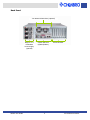
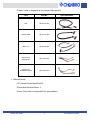
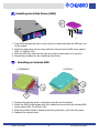
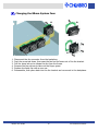
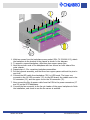
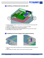
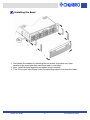
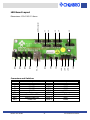
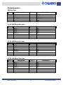
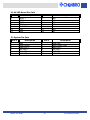
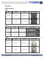
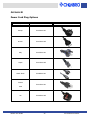
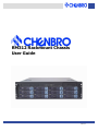
RM312 Rackmount Chassis
User Guide
Rev. 01
Contents
YOUR RACKMOUNT CHASSIS........................................................................1
FEATURES .......................................................................................................1
SPECIFICATIONS ...............................................................................................2
LAYOUT ..........................................................................................................3
INSTALLATION ..............................................................................................5
FOR YOUR SAFETY .............................................................................................5
PARTS LIST .....................................................................................................6
INSTALLING HARD DISK DRIVES (HDD).............................................................8
INSTALLING AN INTERNAL HDD .......................................................................8
INSTALLING A FDD ......................................................................................9
INSTALLING A SLIM CD/DVD-ROM..................................................................9
CHANGING THE 80MM SYSTEM FANS ............................................................... 10
INSTALLING THE BACKPLANE (OPTIONAL ITEM) ................................................... 11
INSTALLING A MOTHERBOARD (OPTIO NAL PART).................................................. 13
INSTALLING THE POWER SUPPLY U NIT (OPTIONAL DEVICE) ..................................... 13
INSTALLING THE GENERAL RACK RAIL K IT (OPTIONAL PART) ................................... 14
INSTALLING THE BEZEL ............................................................................... 15
BACKPLANE BOARD.....................................................................................16
RAID BACKPLANE S UPPORTS: .............................................................................. 16
BACKPLANE LAYOUT ......................................................................................... 17
PIN A SSIGNMENTS ........................................................................................... 18
LED BOARD..................................................................................................20
FEATURES ..................................................................................................... 20
LED BOARD LAYOUT ........................................................................................ 21
PIN A SSIGNMENTS ........................................................................................... 22
APPENDIX A ................................................................................................24
O PTIONAL CABLES ........................................................................................... 24
APPENDIX B ................................................................................................25
POWER CORD PLUG O PTIONS.............................................................................. 25
NOTICES......................................................................................................26
CONTACT INFORMATION ............................................................................27
HEADQUARTERS .............................................................................................. 27
RM312 User Guide
ii
19" Rackmount Chassis
YOUR RACKMOUNT CHASSIS
The RM312 19" rackmount chassis supports a variety of high-density system
configurations and features the latest in server-chassis technology.
Features
Top Cover
Ø Screw-less design for easy installation and maintenance
Ø Quick reference guide affixed to the inside
Front
Ø
Ø
Ø
Ø
Panel Controls and Indicators
Front access USB2.0 ports offer flexibility
Alarm mute button to disable audible warnings
System reset button
LEDs for system signals (power, HDD access, LAN1, LAN2, and failure event)
Hard Drive Trays
Ø 12 hard drive trays (may serve NAS, RAID, or media streaming applications)
Ø Hot-swappable for ease of use
Drive Bays
Ø Two external bays (one slim CD/DVD-ROM and one standard FDD)
Ø Internal HDD bay for operating system
Backplanes
Ø Supports 3pcs of 4-in-1 IDE ATA133/Ultra320 SCSI/SATA backplanes
Motherboard
Ø Extended ATX form factor up to 12”×13”
Ø Supports numerous brands (i.e. Intel ® , Supermicro® , Tyan, Gigabyte™ , Asus® ,
etc.)
CPU
Ø Supports Intel ® P4, Intel ® DP Xeon™ , AMD Athlon™ MP, or AMD Opteron™
Ø Excellent thermal solution for DP Xeon up to 3.06+GHz
PSU
Ø Supports single or redundant 3U power supply
Ø Power output up to 800W (depends on power supply)
Cooling Fans
Ø Four 80mm ball-bearing fans (two 60mm rear fans optional)
Slot Openings
Ø 7 PCI expansion slots at the rear
RM312 User Guide
1
19" Rackmount Chassis
Specifications
Model Name
RM312
Standard
EIA-RS310D
M/B Form Factor
Extended ATX (12"x13")
CPU Type Supported
P4/DP Xeon/Athlon MP/Opteron
Dimension (D*W*H)
660*430*176mm
26*16.9*5.2"
External
Drive
Bays
PSU
Internal
5.25”
1 x slim CD/DVD-ROM
3.5”
1 x FDD
3.5”
1
HDD Trays
12
Form Factor
Single or Redundant
Watts
350W ~ 800W
Indicators
Power On/Off, HDD/LAN activity, fan failure,
and overheat warning
Front Controls
Power On/Off, System Reset, Alarm Reset,
and USB2.0 port x 2
System Security
N/A
Standard
4 × 80mm middle fans
Cooling Fan
Optional
2 × 60mm rear fans
Slot Opening
7
Material
SGCC
Sheet Metal Thickness
1.2mm
Net Weight (chassis only)
15.1kg
Cubic Feet
5.27
Reference Container Load
(single packing)
Backplane
RM312 User Guide
20’
176 units
40’
368 units
IDE/SCSI/SATA
2
19" Rackmount Chassis
Layout
Chassis
Two 60mm Exhaust Fans (optional)
Standard ATX/
Extended ATX M/B
Single or n+1 Redundant
Power Supply (optional)
4x 80mm Easy Swap
Fan Modules
Slim CD-ROM
Internal 3.5" Hard Drive
Standard FDD or Internal HDD
12x Hard Drive
Trays
See Front Panel Inset
for details
Front Access Panel
Front Panel Inset
A
A.
B.
C.
D.
E.
B
C
HDD Tray Activity LEDs (1-12)
USB2.0 Port x2
LAN1 and LAN2 LEDs
Alarm Mute Button
System Reset Button
RM312 User Guide
D
E
F G H
F.
G.
H.
I.
3
I
Failure LED
System HDD Activity LED
Power LED
Power Switch
19" Rackmount Chassis
Back Panel
Two 60mm Exhaust Fans (optional)
Single or n+1
Redundant
Power Supply
(optional)
RM312 User Guide
System I/O Ports
(M/B dependent)
4
Seven PCI Slots
19" Rackmount Chassis
INSTALLATION
For your safety
When deciding on a location for your RM312 rackmount chassis, please take the
following into consideration:
Electric Power:
The power cord is what powers on/off your chassis, so try to
place the chassis near a power outlet for convenience. Next,
be aware of RM312's power rating to avoid overloading its
circuits. Then make sure the connections are grounded
properly.
Temperature:
Whenever dealing with an enclosed environment,
temperature must be a consideration. Inside the chassis, the
temperature will most likely be higher than that of the room
it is located in. To make certain that RM312 operates
effectively and to prevent possible heat-related problems, be
sure to have plenty of ventilation (i.e. additional cooling fans
and extra space between devices).
RM312 User Guide
5
19" Rackmount Chassis
Parts List
• RM312 Rackmount Chassis (P/N: 90-331200-001)
• Accessory Box (P/N: 84-331210-001)
- CD-ROM Adapter (P/N: 80-091801-011)
- Screws and Spacers:
DEVICE
PACKET PART
NO.
HDD Tray
70-000000-149
Internal HDD
70-000000-149
FDD
70-331900-101
Slim CD/DVD-ROM
70-331900-101
SCREW
IMAGE(S)
INSTALLATION TOOL(S)
REQUIRED
Phillips Screwdriver
Phillips Screwdriver
Phillips Screwdriver
Phillips Screwdriver
Phillips Screwdriver
Backplane
70-331900-102
Nut Driver
Phillips Screwdriver
Motherboard
RM312 User Guide
70-331100-101
Nut Driver
6
19" Rackmount Chassis
- Cables: (refer to Appendix A for further cable options)
CABLE
PART NO.
FDD
26-073123-001
CD/DVD-ROM
26-073123-004
HDD 1-to-2
26-073118-007
Big 4P to big
4P/small 4P
26-113215-001
Big 4P to big
4P+250mm big 4P
26-113215-003
CABLE A PPEARANCE
• Optional Items:
- 26” General Device Rack Rail Kit
- 60mm Rear Exhaust Fans x 2
- Power Cord (refer to Appendix B for plug options)
RM312 User Guide
7
19" Rackmount Chassis
Installing Hard Disk Drives (HDD)
?
?
?
1. Press latch towards the right to open the lever release and slide the HDD tray out
of the chassis.
2. Mount the hard drive onto the tray with four screws from the HDD screw packet
(P/N: 70-000000-149).
3. Slide the HDD tray back into the case and press the lever back in to secure it.
4. Repeat the procedure for the remaining hard drives.
Installing an Internal HDD
( STANDARD )
( OPTION )
?
?
?
?
1. Remove the securing screw to slide back and take out the bracket.
2. Attach the HDD to the bracket with four additional screws from the included HDD
screw packet (P/N: 70-000000-149).
3. Slide the bracket forward, following the three guide pins, until it fits into place.
4. Reattach the original screw.
RM312 User Guide
8
19" Rackmount Chassis
Installing a FDD
?
?
?
1. Remove the securing screw to move back and take out the bracket.
2. Remove the bracket's FDD cover screws.
3. Attach the FDD onto the bracket with four additional screws from the included
FDD screw packet (P/N: 70-331900-101).
4. Slide the bracket forward, following the three guide pins, until it fits into place.
5. Reattach the original securing screw.
Installing a Slim CD/DVD-ROM
?
?
?
1. Release the securing screw to slide back and take out the bracket.
2. Release the CD-ROM's cover screws.
3. Attach the slim CD/DVD-ROM onto the bracket with four additional screws from
the included CD-ROM screw packet (P/N:70-331900-101).
4. Slide the bracket forward, following the two guide pins, until it fits into place
5. Reattach the securing screw.
RM312 User Guide
9
19" Rackmount Chassis
Changing the 80mm System Fans
Ž
•
•
1.
2.
3.
4.
5.
6.
Disconnect the fan connector from the backplane.
Push the press tab down, then ease the fan and its frame out of the fan bracket.
Pull the press tab up to release the fan from the frame.
Remove the four screws to take out the finger guard.
Replace the faulty fan with a new one.
Reassemble, then place back into the fan bracket and reconnect to the backplane.
RM312 User Guide
10
19" Rackmount Chassis
Installing the Backplane (optional item)
RM312 supports the following three different backplanes: SCSI, IDE, and SATA.
SCSI Backplane Assembly
IDE Backplane Assembly
RM312 User Guide
SATA Backplane Assembly
11
19" Rackmount Chassis
?
?
?
?
1. With ten screws from the backplane screw packet (P/N: 70-331900-102), attach
the backplane to the bracket in the chassis as shown in the diagram.
2. To support a second backplane, affix three hex copper spacer pins.
3. Next secure both ends of the backplane with two screws on both sides of the
outer chassis.
4. Repeat steps 1-3 for remaining backplane assemblies.
5. For the topmost assembly, use the three hex copper spacers without the pins to
cap it off.
6. Connect the LED cable from backplane (JP1) to LED board. The lower one
connects to the 1U LED connector (J1) on the LED board; the middle one to the
2U connector (J2); and the upper one to the 3U connector (J3).
7. Now connect the Big 4p power cable from the PSU to the power connectors (J7
and J8) on the SCSI backplane.
8. Connect the fan connector to the fan pin header of the upper backplane to finish
the installation, and check to see the fan sensor is enabled.
RM312 User Guide
12
19" Rackmount Chassis
Installing a Motherboard (optional part)
?
?
?
?
?
1. Use the included spacers for support from the motherboard screw packet (P/N:
70-331100-101).
2. Install the I/O gasket that came with your motherboard (M/B).
3. Next align the M/B with the chassis and I/O gasket.
4. The edge with the I/O ports should be placed at the back part of the chassis.
5. Secure M/B to the chassis with a screw.
Installing the Power Supply Unit (optional device)
?
?
1. Place the power supply unit (PSU) into in the area shown and secure it with four
screws.
2. With another two screws, secure it to the other side of the chassis.
RM312 User Guide
13
19" Rackmount Chassis
Installing the General Rack Rail Kit (optional part)
Sliding Rail Guide
(inside facing chassis)
Outer Fixed Rack Rail
Screws
Inner Fixed Chassis Rail
The optional rack rail kit consists of three main parts: a pair of inner fixed chassis
rails, a pair of outer fixed rack rails, and a pair of sliding rail guides. Each pair is
identical, so no special attention is necessary to make the parts match either the left
or the right side. No parts must be removed from the chassis in order to install the
rack rail kit.
1. As they are partially assembled when packaged, you must first disassemble the
rails before installing them.
Remove the inner fixed chassis rail: Pull out until a "click" is heard, then depress
the locking tab and pull the inner rail completely out. Do this for both the left and
right side rail assemblies.
2. Now position the same inner fixed chassis rail along the side of the RM312
chassis. Making sure the holes line up, screw the rail securely to the side of the
chassis. Repeat this procedure for the other rail on the other side.
3. Next position the outer fixed rack rail/sliding rail guide assembly at the desired
location in the cabinet rack, making sure to keep the sliding rail guide facing the
interior of the rack. Screw the assembly securely to the rack using the included
brackets. Repeat the procedure for the other side's assembly, making sure to
match the exact same height and position of the rail guides facing inward.
4. Line up the rear of the inner fixed chassis rails with the front of the outer fixed
rack rails, and slide the chassis towards the rear, keeping even pressure on both
sides.
5. When the RM312 has been eased completely into the rack, you should hear the
locking tabs "click" to finish the installation.
RM312 User Guide
14
19" Rackmount Chassis
Installing the Bezel
?
?
?
1. First detach the handles by removing the two screws from each one. Keep
handles in the event you may need them again in the future.
2. Next, install the bezel supports and tighten screws securely.
3. Then fit the right side of bezel to its corresponding support and snap into place.
RM312 User Guide
15
19" Rackmount Chassis
BACKPLANE BOARD
Raid Backplane Supports:
Ø
Ø
Ø
Ø
Ø
Ø
Ø
Ø
Ø
Ø
Ø
Ø
Ø
SCSI interface: Ultra 320/160 backward compatibility
Hard disk drive 80pin SCA2 Ultra 320/160 backward compatibility
4-bay hard disk drive inrush current control for hot-swapping
SCSI-IN and SCSI-OUT connector (right angle, 68-pin female)
SCSI on board terminator On/Off function and On/Off LED
Hard disk drive Delay_Start or Remote_Start mode function
SCA2 ID setting function default is ID0, ID1, ID2, ID3
5pcs external fan speed monitoring, fan failure buzzer alarm, and red LED
active function
Fan disable function
One on-board temperature sensor with adjustable alarm level (50 C or 60 C);
buzzer sounds when temperature rises above alarm level
2pcs power connectors in big 4-pin, right angle, D-type
Power On LED
4 external LEDs monitoring for HDD installation, HDD access, and fan
overheating fail and buzzer mute connector pin
RM312 User Guide
16
19" Rackmount Chassis
Backplane Layout
Dimensions: 411.60*51.44*2.4mm
S2
J5
J1
BZ1
FAN1
FAN2
FAN3
S3
J2
J7
S6
S4
FAN4
FAN5
J3
JP1
S1
S5
J6
J4
J8
RM312 User Guide
17
19" Rackmount Chassis
Connectors and Switches
No.
J1
J2
J3
J4
J5
J6
J7
J8
JP1
S1
S2
Description
HDD1 SCA2 Connector
HDD2 SCA2 Connector
HDD3 SCA2 Connector
HDD4 SCA2 Connector
SCSI in 68pin Connector
SCSI in 68pin Connector
DC Power Input for Big 4P
DC Power Input for Big 4P
For LED Output Header
Function Set Switch
HDD1 ID-Set Switch
No.
S3
S4
S5
S6
FAN1
FAN2
FAN3
FAN4
FAN5
BZ1
Description
HDD2 ID-Set Switch
HDD3 ID-Set Switch
HDD4 ID-Set Switch
Function Set Switch
Fan Connector
Fan Connector
Fan Connector
Fan Connector
Fan Connector
Buzzer
Pin Assignments
S2, S3, S4, S5: SCSI ID Settings
SCSI ID
Position1
Position2
Position3
Position4
0
1
2
3
4
5
6
7
8
9
10
11
12
13
14
15
Off
On
Off
On
Off
On
Off
On
Off
On
Off
On
Off
On
Off
On
Off
Off
On
On
Off
Off
On
On
Off
Off
On
On
Off
Off
On
On
Off
Off
Off
Off
On
On
On
On
Off
Off
Off
Off
On
On
On
On
Off
Off
Off
Off
Off
Off
Off
Off
On
On
On
On
On
On
On
On
Ø Avoid setting SCSI ID 7 for SCSI drive. It normally hosts the SCSI
host adapter.
Ø The default setting for SCSI drives are from ID0, ID1, ID2, and ID3.
RM312 User Guide
18
19" Rackmount Chassis
S1: Function Settings*
Switch
Switch On
Switch Off
Switch 1
HDD motor spin up delay mode
Normal
Switch 2
HDD motor spin up remote mode Normal
Switch 3
Terminator On
Terminator Off
* With this jumper, the user can set the SCSI HDD motor to start in sequence or
randomly.
S6: Fan and Temperature Settings
Switch
Switch 1
Switch 2
Switch 3
Switch 4
Switch 5
Switch 6
Switch On
FAN 1 sensor disabled
FAN 2 sensor disabled
FAN 3 sensor disabled
FAN 4 sensor disabled
FAN 5 sensor disabled
Temperature Set 50°C
Switch Off
FAN 1 sensor enabled
FAN 2 sensor enabled
FAN 3 sensor enabled
FAN 4 sensor enabled
FAN 5 sensor enabled
Temperature Set 60°C
JP1: Display Board Signals Output
Pin
Pin
Pin
Pin
Pin
Pin
Pin
Output
HDD1 LED +
HDD2 LED +
HDD3 LED +
HDD4 LED +
Fail LED +
Buzzer Mute Switch +
1
3
5
7
9
11
Pin
Pin
Pin
Pin
Pin
Pin
Pin
2
4
6
8
10
12
Output
HDD1 LED HDD2 LED HDD3 LED HDD4 LED Fail LED Buzzer Mute Switch -
Fan 1, Fan 2, Fan 3, Fan 4, Fan 5: Connector Pin Assignments
Pin
1
2
3
Description
GND
VDD
SENSOR
J7 and J8: Big 4P Pin Assignments
Pin
1
2
3
4
RM312 User Guide
Description
VDD
GND
GND
VCC
19
19" Rackmount Chassis
LED BOARD
Features
Ø
Ø
Ø
Ø
Ø
Ø
Ø
Ø
Ø
Ø
Ø
Ø
Ø
PCB Layers: 2
1 HDD power and access LED monitor
1 buzzer alarm mute switch
1 system reset switch
1 system power switch
1 power green LED indicator
1 local HDD yellow LED indicator
1 fails red LED indicator
2 USB port
2 LAN LED indicator
4 connectors for 1U, 2U, 3U, 4U LED boards
2 x 10 pin connectors for USB port
1 system connector
RM312 User Guide
20
19" Rackmount Chassis
LED Board Layout
SW3
J5
LED6-3
LED6-2
LED6-1
J4
J2
SW2
J3
SW1
J1
LED5
USB。ム2
LED4
LED3
LED2
LED1
USB Connector
Dimensions: 130.0*45.0*1.6mm
Connectors and Switches
NO.
J1
J2
J3
J4
J5
SW1
SW2
SW3
RM312 User Guide
Description
1U LED
2U LED
3U LED
4U LED
System
Alarm Mute SW
System Reset SW
Power SW
NO.
LED1
LED2
LED3
LED4
LED5
LED6-1
LED6-2
LED6-3
21
Description
HDD1
HDD2
HDD3
HDD4
LAN Activity
Fail
HDD
Power
19" Rackmount Chassis
Pin Assignments
USB Pin Outs
Pin #
1
3
5
7
9
Description
USB1
USB1
USB1
USB1
Key
Power
Data Data +
GND
Pin #
2
4
6
8
10
Description
USB2 Power
USB Data USB2 Data +
USB2 GND
None
J1: 1U LED Board Pin Outs
Pin #
1
3
5
7
9
11
13
Description
LED11 +
LED12 +
LED13 +
LED14 +
+5V VCC
Mute
None
Pin #
2
4
6
8
10
12
14
Description
GND
GND
GND
GND
Fail
GND
Key
J2: 2U LED Board Pin Outs
Pin #
1
3
5
7
9
11
13
Description
LED21 +
LED22 +
LED23 +
LED24 +
+5V VCC
Mute
None
Pin #
2
4
6
8
10
12
14
Description
GND
GND
GND
GND
Fail
GND
Key
J3: 3U LED Board Pin Outs
Pin #
1
3
5
7
9
11
13
Description
LED31 +
LED32 +
LED33 +
LED34 +
+5V VCC
Mute
None
RM312 User Guide
Pin #
2
4
6
8
10
12
14
Description
GND
GND
GND
GND
Fail
GND
Key
22
19" Rackmount Chassis
J4: 4U LED Board Pin Outs
Pin #
1
3
5
7
9
11
13
Description
LED41 +
LED42 +
LED43 +
LED44 +
+5V VCC
Mute
None
Pin #
2
4
6
8
10
12
14
Description
GND
GND
GND
GND
Fail
GND
Key
J5: System Pin Outs
Pin #
1
3
5
7
9
11
Description
Reset
Power Switch
Power LED +
HDD LED +
LAN1 LED +
LAN2 LED +
RM312 User Guide
Pin #
2
4
6
8
10
12
Description
Reset GND
Power Switch GND
Power LED HDD LED LAN2 LED LAN2 LED -
23
19" Rackmount Chassis
APPENDIX A
Optional Cables
USB:
TYPE
LENGTH
PART NO.
Intel Spec
750mm
26-033219-001
Universal Spec
750mm
26-033219-002
CABLE A PPEARANCE
IDE:
TYPE
LENGTH
PART NO.
ATA-133 IDE
700mm
26-073215-001
ATA-133 IDE
560mm
26-073118-006
CABLE A PPEARANCE
SATA:
TYPE
LENGTH
PART NO.
Serial ATA
700mm
26-123215-001
Serial ATA
560mm
26-123215-002
RM312 User Guide
24
CABLE A PPEARANCE
19" Rackmount Chassis
APPENDIX B
Power Cord Plug Options
COUNTRY/REGION
PART NO.
Europe
34-032100-001
Greece
34-073100-002
Italy
34-023100-001
Japan
34-013100-002
South Africa
34-083100-001
CONNECTOR
Taiwan
34-013100-001
USA
UK
RM312 User Guide
34-043100-002
25
19" Rackmount Chassis
NOTICES
© 2003 Chenbro Micom Co., Ltd.
All rights reserved
Chenbro Micom Co., Ltd. reserves the right to make improvements to the products described in this
manual at any time. Specifications and features are subject to change without prior notice.
No part of this manual may be reproduced, copied, translated, or transmitted in any form or by any
means without the prior written permission of Chenbro Micom Co., Ltd. Information provided in this
manual is intended to be accurate and reliable. However, Chenbro Micom Co., Ltd., assumes no
responsibility for its use, nor for any infringements upon the rights of third parties, which may result
from its use.
Acknowledgements
Intel® Pentium® 4, Intel® XeonT M , Intel® SE7500WV2 are trademarks of Intel Corporation. AMD
AthlonT M MP and AMD OpteronT M are trademarks of Advanced Micro Devices, Inc. 3ware® is a
trademark of 3ware Inc. Promise® is a trademark of Promise Technology, Inc. Serverworks™ is a
trademark of Serverworks Corporation.
All other product names or trademarks mentioned herein are the properties of their respective owners.
P/N:
Version 1.0
RM312 User Guide
26
19" Rackmount Chassis
CONTACT INFORMATION
Headquarters
CHENBRO MICOM CO., LTD.
150 Jian Yi Road, 15F
Chung Ho City 235, Taipei County
Taiwan
Tel: +886 (2) 8226-5500
Fax: +886 (2) 8226-5423
E-mail: [email protected]
Website: www.chenbro.com.tw
CHENBRO MICOM (USA) INC.
2260 S. Haven Ave., Unit E
Ontario, CA 91761
USA
Tel: 1-909-947-3200
Fax:1-909-947-4300
E-mail: [email protected]
CHENBRO UK
8 Ledbury Avenue, Davyhulme
Manchester, M41 7AL
UK
Tel: +44 (161) 749-9015
Fax: +44 (161) 749-9219
E-mail: [email protected]
CHENBRO EUROPE B.V.
De Pinckart 54, 5674 CC Nuenen
The Netherlands
Tel: +31 (40) 295-2045
Fax: +31 (40) 295-2044
E-mail: [email protected]
CHENBRO CHINA BEIJING
Room 1502-1503 FUDI TOWER
No.29, Yard #9, AnNingZhuang West Road
Haidian District, Beijing 100085
China
Tel: +86 (10) 8274-3036/37/38/39
Fax: +86 (10) 8274-3035
E-mail: [email protected]
RM312 User Guide
27
19" Rackmount Chassis