1
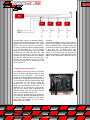
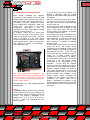
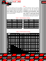
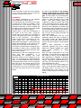
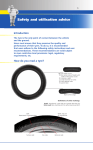
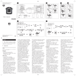
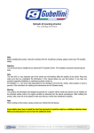
tecnology
Safety
PowerTraction
ControlRace
Performance
1
SECURITY
During the installation of this product, it is recommended to position the
motorbike in such a way that is cannot cause any injury or damage by falling
down or moving forward or backward; it is recommended to use the rear stand
or, if necessary, the wheel lock.
Make sure that the injection system is always turned off and that the electrical
equipment is not being powered during the installation of this product (and, as
well as, during all assembly phases indicated in this manual). When adding or
removing electrical cables or wiring to/from the motorcycle’s equipment, always
be sure to remove the negative battery terminal before the positive battery
terminal. During reassembly phases, connect the negative terminal last in order
to avoid short circuiting the electrical equipment.
INSTALLATION RECCOMENDATIONS
DO NOT RUSH! When installing the GRIPone control unit, make sure that the unit
is protected from excessive vibrations and surrounding elements and that it is
clamped firmly. When you use the adhesive parts (for setting up the control unit
or cables), make sure that the mounting surfaces are clean and free of dust or
grease by cleaning them with degreasing solution.
When positioning the wiring, make sure that the wires cannot be pinched or
crushed which may cause subsequent malfunctions, clamp them as necessary.
For safe and professional assembly, it is recommended that you solder the
connections when possible and use thermo-tightening bands to isolate the various
conductors. Place the hot part of the welder on the ends of the wires before
putting them in contact with each other. Do not hesitate to contact the
vendor/supplier for assistance if you encounter any difficulties with the installation
of this device.
WARNING! The GRIPone control unit must be placed
where the operating temperature does not exceed 65°C
and should be installed where it will be protected from
vibrations and surrounding elements.
Locate a flat
surface on which to secure the control unit. Do not secure
the unit until the installation of all other components has
been completed and the wiring has been secured.
ControlRace
Performance
tecnology
Safety
PowerTraction
2
1. What is GRIPone
In sports, every bike is continually found to
be in critical situations in which the rear
wheel loses its grip during acceleration.
GRIPone is a universal device, designed to be
easily attached to any vehicle and through
which it is possible to control the level of
sliding at the rear wheel.
Moment by
moment, GRIPone checks the conditions of
the motorbike on which it is mounted and
manages the power to restore the optimal
running conditions, increasing stability and
improving the overall yield.
2. How does GRIPone work
GRIPone is an electronic traction control
system consisting of two elements:
the
GRIPone control unit and two speed sensors.
Working in unison, they continuously monitor
the traction conditions for the motorcycle.
Under normal circumstances (i.e. when no
sliding is occurring), the control unit does not
intervene in any way with the motorcycle.
When above-normal sliding is detected, the
control unit reduces the engine power until
normal roadholding is restored. Once the
rear tire re-establishes correct adhesion and
the sliding is detected to be within the
accepted threshold, the control unit ceases to
reduce the engine power.
ControlRace
Performance
tecnology
Safety
PowerTraction
3
3. Installation of the Control Unit
The installation of the system involves
connecting the GRIPone control unit to the
power wiring of the motorcycle and linking
the two speed sensors in close proximity to
both wheels.
The electrical connection of the sensors is
simply done by inserting the male 3-pole
connectors (located at the end of the sensors’
cable) into the female connectors on the
GripONE control unit.
Through the 5-pole connector and through
the supplied cable, it is possible for the
GRIPone control unit to interface with the
electrical equipment of the motorcycle. The
installation of the GRIPone control unit is
possible on all motorcycles with inductive or
transistor ignitions (or on bikes with injection
system of a single injector per cylinder). The
GRIPone control unit can be installed on CDI
control units only through an additional
interface filter (available upon request).
Inductive or Transistor Ignitions (for 2-,
3-, or 4-cylinder motorcycles).
Through a tester set for detecting continual
voltages, verify the voltage between point A
and ground;
Through a tester set for detecting continual
voltages, verify the voltage between point B
and ground; If a voltage equivalent (or
almost equivalent) to 12 volts is detected at
any one of the two points, the ignition is a
transistor type (and not a CDI type). In
some cases, it is necessary to start the
engine in order to detect the voltage.
If a voltage equivalent (or almost
equivalent) to 12 volts is not detected in
either of the two points, then the ignition is
a CDI type.
If the ignition system is a transistor or
inductive discharge type, then proceed with
connecting the electrical cables of the
motorcycle as described below.
-Pole N.5:
Power (10 – 18 volt) under
the ignition key;
-Pole N.4:
Ground (GND) or negative
pole of the battery;
In order to verify whether the ignition falls
into this category, refer to the user’s manual
for the motorcycle or proceed as follows.
Disconnect the connector from one of the
coils on the motorcycle;
Turn the key and activate the main switch to
power the vehicle;
ControlRace
Performance
tecnology
-Pole N.1: Impulsive signal relative to the
engine rpm (detectable by the speedometer
of the motorcycle or by the positive pole of
the pickup phase or by the negative pole of
the injector). Do not detect the engine’s
rpm linking directly to one of the coils. The
detected signal should deliver a single
pulse for every driveshaft revolution
(or for every camshaft revolution). If the
signal detected is more than one pulse,
then the system may not be functioning
correctly.
Safety
PowerTraction
4
Connect poles 2 and 3 as described below.
Detach the cable from one of the coils on the
positive pole (as demonstrated in the figure
above). The choice of the coil is irrelevant.
In order to locate the above-mentioned cable,
it is recommended to use the graphic
diagrams of the motorcycle. Once the cable
is detached, the cable will have two ends
(that we will refer to as A and B). One end
connected to the positive pole of the battery
(A) and the other directly to the coil (B).
Connect end (B) directly to the coil of the
motorcycle at pole No. 3 and the other end
(A) to pole No. 2.
Caution!
During the installation of the system, keep in
mind that the GRIPone control unit does not
have an ON/OFF switch. For this reason, the
power that is applied to the heads of Pole No.
5 and Pole No. 4 should come from
underneath the key lock or through the main
switch of the motorcycle (or through an
appropriate switch) to avoid draining the main
battery of the motorcycle (when the bike is
off).
4. Installation of the Sensors
The GRIPone control unit uses two proximity
sensors to detect the rotation speed of both
wheels of the motorcycle.
The sensors
consist of a filleted M8x1 cylinder which is
connected to the signal cable (already wired).
The connectors that are located at the ends
of the cable of the sensors should be
connected to the two 3-pole connectors
located on the GRIPone control unit. It is
important not to confuse the front sensor
with the rear sensor when connecting two
sensors. Please refer to the figure on the
right to avoid making such an error.
The proximity sensors should be applied to
the motorcycle through rigid brackets, so that
at every complete revolution of the wheel
they detect the passage of one or more
metallic (ferrous) objects.
ControlRace
Performance
tecnology
Safety
PowerTraction
5
The sensors detect the passage of a ferrous
object if it is not further away than 2 mm or
closer than 0.5 mm. It is advised to set the
distance between sensor and ferrous object
between 1.3 mm and 0.8 mm.
FRONT WHEEL
It is recommended to apply the sensor in
correspondence with the fixing screws of the
flange of the disk brakes through a rigid
bracket fixed to the front fork. The sensor
will, therefore, detect up to 6 pulses for every
complete revolution of the wheel.
The
metallic parts that pass in proximity to the
sensor (for example, the fixing screws of the
disk brake) should have a surface and a cross
section as flat as possible. If hollow head
screws are used, then the system will not
function correctly. The pulses detected by
the sensor should be a minimum of 3 and a
maximum of 6. The screws or the ferrous
bodies detected should be equidistant from
one another.
REAR WHEEL
It is recommended to apply the sensor in
correspondence with the fixing screws of the
rear crown or of the disk brakes. The sensor
will, therefore, detect up to 6 pulses for every
complete revolution of the wheel.
The
metallic parts that pass in proximity to the
sensor (for example, the fixing screws of the
disk brake) should have a surface and cross
section that are as flat as possible. If hollow
head screws are used, then the system will
not function correctly. The pulses detected
by the sensor should be a minimum of 3 and
a maximum of 6. The screws or the ferrous
bodies detected should be equidistant from
one another.
POSITIONING
During the positioning of the sensors, it is
necessary to verify the distance between the
head of the sensor and the head of the
ferrous object (for example, the fixing screws
of the disk).
ControlRace
Performance
tecnology
Torque = 0.5 Kg/m
After having placed both sensors and
having
completed
the
electrical
connections, power the GRIPone control
unit and turn the wheel to empty. If the
sensors are correctly positioned, upon
passing the ferrous material, the led display
will light up on the back of the sensor itself.
IMPORTANT
When
installing
the
sensors
in
correspondence with the fixing screws of
the disk brake or of the rear crown, be
careful not to use (as ferrous objects)
hollow head screws (like hollow screws or
bolts or Allen head screws).
If the
motorcycle is equipped with this type of
screws, it is necessary to replace them with
full head screws.
Every ferrous object
detected by the sensor should be
equidistant from the others. If these two
conditions are not satisfied, the system will
not function correctly.
NUMBER OF PULSES
The number of pulses detected by the
sensors for each complete wheel revolution
is a very important factor in the functioning
of the system. Equivalent to the speed of
the motorcycle, a greater number of pulses
allows the system to control with more
frequency the rotation speed of the wheels
and the status of the motorcycle’s engine.
In cases of sliding, the control unit will
intervene with greater speed.
Safety
PowerTraction
6
5. Configuration of the Control Unit
After having completed the electrical
connections of the GRIPone control unit and
having positioned the sensors in the manner
indicated, to obtain the correct functioning of
the system it is, then, necessary to set up
three configuration parameters within the
control unit.
The setting of the three
configuration parameters is done by
positioning the three click registers located
inside the control unit itself.
To continue, remove the four screws that
secure the top cover of the control unit in
order to gain access to the inside. Once the
cover is removed, you will find various
components inside the control unit as shown
in the following figure. Each one of the three
click registers is related to a parameter:
Level, Ratio and Pulse.
The three above-listed parameters are
substantially involved in the functioning of the
control unit and, for this reason, must be set
up in the correct manner before using the
traction control system.
EXPLANATION
PARAMETERS
OF
THE
CONFIGURATION
The first group goes from position 0 to
position 7 (included), while the second
group goes from position 8 through position
F (included).
Only one of the two groups may be used.
The choice of one of the two depends on
the type of the engine rpm signal detected
by the control unit.
If the engine rpm signal is detected by the
sensor positioned on the camshaft (1 pulse
every 2 drive shaft rpm), then the first
group of values (from position 0 to position
7 included) should be used.
If the engine rpm signal is detected by the
sensor positioned on the driveshaft or by
the speedometer (1 pulse every drive shaft
rpm), then the second group of values
(from position 8 to position F included)
should be used.
The first value of every group (0 for the first
group and 8 for the second group)
corresponds to the disabling of the control
system (whatever the running condition of
the motorcycle may be). In this case, the
control unit does not exercise any type of
control be it under normal running
conditions or in the presence of sliding.
The next value of each group (1 for the first
group and 9 for the second group)
corresponds to the configuration for less
sensitivity.
In this case, the GRIPone
control unit exercises a slight control only in
the presence of an elevated level of sliding.
Scrolling upwards through the values of
each group (towards value 7 of the first
group and towards value F of the second
group) increases the sensitivity of the
control system. When increasing the
sensitivity of the system, less sliding is
needed for the traction control to be
ignited. Increasing the sensitivity of the
system will also increase the level of control
that the GRIPone control unit exercises over
the engine.
Level
The level parameter determine the sensitivity
of the control unit to the loss of adhesion of
the motorcycle (due to the sliding of the rear
wheel). The register is adjustable to 16
positions (0, 1, 2, 3, 4, 5, 6, 7, 8, 9, A, B, C,
D, E, F ) which are subdivided into two
distinct groups.
ControlRace
Performance
tecnology
Safety
PowerTraction
7
Pulse
Ratio
The PULSE parameter informs the GRIPone
control unit of the number of pulses detected
by the two speed sensors for each complete
wheel revolution. Based on the number of
pulses detected by the front and rear
sensors, set this parameter according to the
values reported in table 1.
The RATIO parameter informs the GRIPone
control unit on the ratio between the
development of the rear tire and the
development of the front tire (RATIO = Rear
Development / Front Development). Based
on the development of the tires (front and
rear), select the RATIO value following
reference table 2. The development of the
tires should be measured using a measuring
tape in proximity to the center of the wheel.
Table 1 – Pulse Parameter Setting
REAR WHEEL FRONT WHEEL VALUE TO SET
PULSES
PULSES
3
3
3
3
4
4
4
4
3
4
5
6
3
4
5
6
REAR WHEEL FRONT WHEEL VALUE TO SET
PULSES
PULSES
0
1
2
3
4
5
6
7
5
5
5
5
6
6
6
6
3
4
5
6
3
4
5
6
8
9
A
B
C
D
E
F
Table 2 – Ratio Parameter Setting
REAR WHEEL DIMENSION (mm)
FRONT WHEEL DIMENSION (mm)
1950 1960 1970 1980 1990 2000 2010 2020 2030 2040 2050 2060 2070 2080 2090 2100
1850
6
6
8
8
9
9
B
B
C
C
D
D
E
E
F
1860
4
6
6
8
8
9
9
B
B
C
C
D
D
E
E
F
1870
4
4
6
6
8
8
9
9
B
B
C
C
D
D
E
E
1880
3
4
4
6
6
8
8
9
9
B
B
C
C
D
D
E
1890
3
3
4
4
6
6
8
8
9
9
B
B
C
C
D
D
1900
2
3
3
4
4
6
6
8
8
9
9
B
A
C
C
D
1910
2
2
3
3
4
4
6
6
8
8
9
9
A
A
C
C
1920
1
2
2
3
3
4
4
6
6
8
8
9
9
A
A
C
1930
1
1
2
2
3
3
4
4
6
6
8
7
9
9
A
A
1940
0
1
1
2
2
3
3
4
4
6
6
7
7
9
9
A
1950
0
0
1
1
2
2
3
3
4
4
5
5
7
7
9
9
0
0
1
1
2
2
3
3
4
4
5
5
7
7
9
0
0
1
1
2
2
3
3
4
4
5
5
7
7
0
0
1
1
2
2
3
3
4
4
5
5
7
0
0
1
1
2
2
3
3
4
4
5
5
0
0
1
1
2
2
3
3
4
4
5
0
0
1
1
2
2
3
3
4
4
0
0
1
1
2
2
3
3
4
0
0
1
1
2
2
3
3
0
0
1
1
2
2
3
0
0
1
1
2
2
1960
1970
1980
1990
2000
2010
2020
2030
2040
2050
ControlRace
Performance
tecnology
Safety
PowerTraction
F
8
Once the position of the three click registers
is set, close the control unit and screw the
top back in with the four screws.
Be aware that the use of the traction
control system does not prevent falls
caused by the inappropriate use of the
gas. For this reason, it is recommended to
experiment with the functioning of the
system by taking repeated tests or small
steps.
Only after having gained full
confidence in using the system and having
clearly understood how the system works,
you can try to adjust the Level parameter.
About the Level parameter, remember that
by moving the value towards the 0 (or the 8
for the second group) reduces the effect of
the system, while moving towards the 7 (or
the F for the second group) increases the
effect of the system.
Take into consideration that the Level
parameter adjusts the point of ignition of
the system (moving the sliding threshold
toward high or low) and, at the same time,
the type of power cutting on the propulsion
system.
Once a good compromise is found
(especially regarding the power cutting)
among the settings available, the system
offers greater possibility for setting
adjustments.
Once the right configuration of the Level
parameter is found and having appreciated
the control of power, you can adjust the
Ratio parameter to anticipate or postpone
the ignition without changing the power
cutting. Modifying the Ratio parameter, in
fact, may “fool” the GRIPone system on the
real ratio between the tires.
If you move one or two clicks toward the F
value, you will achieve greater sensitivity to
the sliding, while if you move one or two
clicks toward the 0 (zero) value, you will
achieve a lesser degree of sensitivity to the
sliding.
COMMENTS
The optimal configuration of the GRIPone
system depends on various factors.
The functioning may vary based on the type
of motorcycle on which it is installed. If the
motorcycle has a four-cylinder engine, the
electronic intervention in case of drifting will
be different with respect to that which would
be obtained by two-cylinder engines.
Another factor to take into consideration is
the profile of the tires used. Using the
“racing” type of rear wheel, the real rolling of
the tire will greatly vary due to the angle of
bend of the motorcycle.
The GRIPone
system could react very sensitively to a “low”
bend angles and less sensitively to
intermediary bend angles. A third factor that
affects the functioning of the system is the
driving style of the rider of the motorcycle.
If the rider is accustomed to revving the gas,
the GRIPone system will be activated with
more frequency as opposed to when the rider
does so more slowly.
After having run the first configuration of the
Pulse
and
Ratio
parameters,
it
is
recommended to configure the Level
parameter based on the experience of the
rider. For professional and semiprofessional
riders, it is recommended to start off with an
intermediate value (value 3 for the first group
and value B for the second group) for the
Level parameter. For non-professional riders,
it is advised to use more conservative values
(6 for the first group and E for the second
group).
Ruota posteriore (mm)
Ruota anteriore (mm)
1950 1960 1970 1980 1990 2000 2010 2020 2030 2040 2050 2060 2070 2080 2090 2100
1850
6
6
8
8
9
9
B
B
C
C
D
D
E
E
F
1860
4
6
6
8
8
9
9
B
B
C
C
D
D
E
E
F
1870
4
4
6
6
8
8
9
9
B
B
C
C
D
D
E
E
1880
3
4
4
6
6
8
8
9
9
B
B
C
C
D
D
E
1890
3
3
4
4
6
6
8
8
9
9
B
B
C
C
D
D
1900
2
3
3
4
4
6
6
8
8
9
9
B
A
C
C
D
1910
2
2
3
3
4
4
6
6
8
8
9
9
A
A
C
C
1920
1
2
2
3
3
4
4
6
6
8
8
9
9
A
A
C
1930
1
1
2
2
3
3
4
4
6
6
8
7
9
9
A
A
1940
0
1
1
4
4
6
6
7
2 -Sensitive
2
3
3
<<
ControlRace
Performance
tecnology
Safety
PowerTraction
F
7
9
9
A>>
+Sensitive
9
6. Features
Power:
Min 12 Volt - Max 24 volt
Dimension
78x52x28 (mm)
Weight:
200g
Min operational speed:
approximately 30 Kmh
Max operational speed:
approximately 360 Kmh
Max operational RPM:
approximately 20000 RPM
Front ty re dimension min configuration:
185 cm
Front ty re dimension max configuration:
220 cm
Rear ty re dimension min configuration:
185 cm
Rear ty re dimension max configuration:
220 cm
Wheel pulses:
Max:6 – Min:3
ControlRace
Performance
tecnology
Safety
PowerTraction
10
KITS and PARTS
Description
Kit GRIPone BASE
Code
KGRIPONE-BASE
GRIPone BASE control unit
CGRIPONE-BASE
Inductive speed sensor
VSENS-NPN
Not wired
3-pole female connector
C3P-FEMALE
Complete connector to solder
3-pole male connector
C3P-MALE
Complete connector to solder
5-pole female connector
C5P-FEMALE
Contact container
5-pole male connector
C5P-MALE
Contact container
5-pole female contact connector
CC-SUPERSEAL-FEMALE
Contacts to crimp
5-pole male contact connector
CC-SUPERSEAL-MALE
Contacts to crimp
Seal – conductor
GT-SUPERSEAL
5-pole connector Cover
CC-SUPERSEAL
ControlRace
Performance
tecnology
Note
Contents: GRIPone BASE control unit, inductive sensors of
speed (wired), user’s manual
Safety
PowerTraction
11
Speed Sensor:
Typology: inductive proximity;
POWER: 12-24 Volt;
EXIT: NPN NO – open collector;
Shielded: YES;
Distance of Detection: up to 2mm;
Work Frequency: 0 – 1500 Hz;
Dimensions: M8 x 1;
Operating Temperature: -40° +85°;
Coating Material: Stainless Steel;
Torque: maximum 0.5 Kg/m;
Pin-Out
(3) Brown: power (+12v);
(1) Blue: GND;
(2) Black: Signal;
The figure to the right shows how to correctly
wire the speed sensor to the 3-pole
connector. The graphic is intended to show a
visual of the soldered side.
ControlRace
Performance
tecnology
Safety
PowerTraction
12
3 pole male connector
3 pole female connector
Superseal 5-pole Connector
Male
Female
ControlRace
Performance
tecnology
Safety
PowerTraction
13
Note
ControlRace
Performance
tecnology
Safety
PowerTraction
14
More informations available on web site http://www.diegogubellini.com
made by
Dealer:
ALL PRODUCTS PRESENTED IN THIS MANUAL ARE ONLY INTENDED FOR PRIVATE USE, AND NOT FOR USE IN PUBLIC
ARENAS, AS WELL AS NOT FOR USE ON STREET MOTORCYCLES. GUBELLINI RESERVES THE RIGHT TO MAKE ANY
CONSTRUCTION MODIFICATION TO THE PRODUCTS PRESENTED IN THIS MANUAL. EXCEPT FOR ERRORS AND
OMISSIONS. TRADEMARKS AND MODELS OF THE MOTORCYCLES MENTIONED IN THIS MANUAL ARE REGISTERED AND
ARE THE PROPERTY OF THE RESPECTIVE MOTORCYCLE MANUFACTURERS. THE SAME ARE PRESENTED IN SOME
PHOTOGRAPHS ONLY AS EXAMPLES FOR BETTER VISUAL RENDERING OF PRODUCTS OF OUR MANUFACTURE.
GUBELLINI DECLINES ANY RESPONSIBILITY FOR ANY POSSIBLE DAMAGES OR JUDGMENTS DERIVING FROM THE
PROPER OR IMPROPER USE OF THE COMPONENTS OF OUR MANUFACTURE. NO PART OF THIS PUBLICATION MAY BE
REPRODUCED IN WHOLE OR IN PART WITHOUT THE PERMISSION OF GUBELLINI
ControlRace
Performance
tecnology
Safety
PowerTraction