1
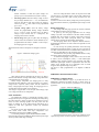
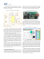
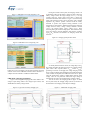
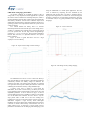
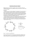
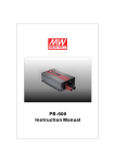
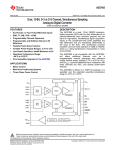
STBCFG01,
ST's new highly integrated switch mode Li-Ion battery charger
Agatino Alessandro, Adele Castorina, Giorgio Catanzaro, Barbaro Marano, Federico Musarra
ABSTRACT
Today’s portable applications are integrating ever more
multimedia functions, each with different power needs. Battery
charge indicators – or fuel gauges - have become essential for
managing devices such as smartphones, laptops or digital cameras.
Accurate “time remaining” predictions enhance the user’s
experience, and can be critical in certain types of portable
electronics such as medical devices.
ST has combined a powerful and configurable switching
battery charger with an accurate Voltage mode Fuel Gauge to
simplify charging and battery monitoring.
INTRODUCTION
First in the world, the STBCFG01 switch mode battery
charger for single cell Li-Ion batteries integrates a highly accurate
voltage mode fuel gauge to monitor the battery’s state of charge.
The device also provides a 5 V output to supply USB OTG (OnThe-Go) bus powered devices in addition to an LDO linear voltage
regulator to support system boot in dead battery conditions.
STBCFG01 uses accurate measurements of the battery
voltage which allows the estimation of the battery’s state-of-charge
(SOC) without a current sensing resistor.
The switching charger works together with the fuel gauge to
simplify monitoring features and to save current consumption
when the device is not charging.
The battery charger features a smart input current limit: the
maximum input current can be selected through the I²C interface,
and if the input voltage drops below a programmable threshold,
even if the selected maximum current limit current has not been
reached yet, the dynamic input current limit function is activated
preventing the input current from increasing further. The dynamic
input current limit function can be disabled, if necessary.
An automatic input pre-bias load makes the device suitable
for applications using voltage sources requiring a minimum
external load for the correct regulation.
A user level I²C interface lets a microcontroller configure all
the functions of the device easily.
Figure 1 shows the device’s simplified block diagram.
All of this is packed into a space-saving 2.3 x 2.2 mm2 CSP
that makes the STBCFG01 an ideal fit for all portable and
wearable applications where size, efficiency and cost are of major
concern.
silicon temperature through dedicated sensing structures.
Additionally, to accommodate the evolution of lithium battery
technologies, the regulated battery floating voltage can be
programmed from 3.52 V to 4.78 V.
The device's system architecture allows reverse use of the
switch-mode buck converter, resulting in a 500mA USB on-the-go
(OTG) boost regulator, and providing power for USB peripherals.
The device can work up to a 100% duty cycle and blocks
reverse current from battery to input when the input voltage is
disconnected or is lower than battery voltage.
The charger uses an innovative architecture where the analog
comparators needed to manage the charging cycle have been
implemented in a digital way using the fuel gauge’s ADC
converter, ensuring a high accuracy and reducing the device
dimensions.
The usage of the fuel gauge as an accurate voltmeter allows a
voltage loop accuracy up to 0.5% through an auto adjustment
strategy.
Figure 1 - Architecture of STBCFG01
Charging Cycle
To protect the battery and maximize mobile device usage
time, the STBCFG01 implements the charging cycle in 5 phases
(see Figure 2): tickle charge, pre-charge, fast charge, constant
voltage (CV), and end of charge.
•
STBCFG01’s FEATURES
Charger Architecture
The STBCFG01 employs a high-efficiency DC-DC
synchronous buck converter, operating at 2MHz or 3MHz,
capable of supplying 1.25 A. The switching frequency can be
selected through the I²C interface.
The device integrates several control loops regulating the
output current and voltage, the input current and voltage and
•
Trickle charge: when the battery is deeply discharged
(< 2V) the device is in trickle charge mode and charges
the battery in linear mode with a low current, around
45mA up to the trickle charge threshold. This mode is
used to wake up batteries in dead battery conditions (the
internal battery pack’s protection switch is open).
Pre-charge phase: as soon as the battery voltage enters
the pre-charge range (2V < VBAT < 3V), the device starts
the switch-mode charging and increases the charging
current up to the pre-charge current level (100mA or
•
•
•
450mA, selectable) to make the system voltage rise
quickly up to a level that allows the system to wake up.
Fast-charge phase: When the battery voltage is above
the pre-charge threshold (VBAT > 3V), the STBCFG01
enters the fast-charge mode and increases the charging
current up to the IFAST value, which can be programmed
up to 1.25A.
Constant voltage phase: when the battery voltage
reaches the programmable floating voltage threshold
(VFLOAT, 3.60V to 4.70V in 20mV steps), the battery
voltage is kept constant and, as a consequence, the
charging current starts to decrease.
End of charge: during the CV phase when the charging
current reaches the termination current threshold (ITERM,
programmable from 50mA to 300mA in 25mA steps),
the charging process is stopped.
All the transitions between each phase are managed in a smooth
way.
Figure 2 - STBCFG01 charging cycle
The Over Voltage Protection (OVP) circuit protects the USB
port when the IC is providing power in boost mode. Output short
circuit protection and coil’s peak current protections are also
implemented.
In order to avoid excessive battery voltage drop in boost operation,
the OTG mode also features a programmable input average current
limit.
Battery Fuel Gauge
The voltage mode fuel gauge provides an accurate evaluation
of the Lithium-Ion battery’s state of charge.
At power-up, the fuel gauge algorithm uses the voltage
reading to provide a first evaluation of the SOC based on battery
modeling data. The evolution of voltage is then used to track the
changes of the SOC while cycling the battery. The external
software driver performs the temperature compensation.
The fuel gauge block can be adapted to different batteries.
Programmable parameters are used to tailor the algorithm to each
battery model.
In order to keep the optimal performance and avoid losing
information learned during battery cycling, the user is supposed to
save data contained in the device's volatile memory when power is
removed. The same data has to be restored at power-up.
The STBCFG01 also provides programmable alarms to notify
low battery voltage and low SOC conditions.
To enhance fuel-gauging accuracy with an error of 0.5% and
to reduce current consumption (25uA), a 14-bit Delta-Sigma
modulator using switched capacitors (SC) technique with fullydifferential input-output structure is implemented. The ADC also
reduces errors through state of art techniques such as nested
choppers and a digital moving average filter.
The device is fully programmable to be adapted to different
batteries.
STBCFG01's EVALUATION TOOLS
Other charger functions performed by the device are battery
detection and automatic recharge when battery voltage falls below
a threshold after the end of charge
Battery charger temperature and charging state are fully
monitored for fault conditions. In the event of battery over-voltage,
charger timers’ expiration, battery failure, and the condition of
battery voltage higher than input voltage, the charging process is
stopped and an interrupt signal can be generated.
The charger is stopped also in case of input under-voltage, input
over-voltage, and silicon over-temperature.
STBCFG01’s evaluation board
The STEVAL-ISB033V1 (Figure 3) provides full access to
STBCFG01’s functions and allows the user to quickly set-up an
evaluation bench to test the device performance in a real world
application.
Figure 3 - STEVAL-ISB033V1
OTG Architecture
The STBCFG01 features a bidirectional switching power
manager that can power an application and charge the battery using
the USB connector’s voltage as input source. Operating in reverse
mode, the same switching regulator can take power from the
battery to generate 5V on the USB connector and deliver up to
500mA for USB OTG applications without any additional
components.
The boost converter that implements the OTG function is a
peak current mode control with slope compensation. The
compensation network works at 2MHz or 3MHz.
A controlling technique of pulse width modulation (PWM)
mode and pulse frequency modulation (PFM) mode keeps the high
efficiency within width range of loading.
The board includes all passive components needed for proper
operation and provides several test points to monitor the device’s
voltage levels. Header connectors give access to the I²C
interface and digital IOs and allow connection to the power
supplies. A micro-USB receptacle can be used to supply the board
from a USB port or wall charger.
interface to access all the device’s configuration registers and
monitor their status. The interface board (Figure 5) uses the USB
interface to connect to the PC running the control software while
the I²C bus is used to control the STBCFG01 evaluation board.
Figure 4 - STEVAL-ISB033V1 schematic diagram
Figure 5 - USB-GPIO Interface board
The STBCFG01 GUI is arranged in four different tabs.
The “Application” tab (Figure 6) provides a quick overview of
device status, battery voltage and SOC. A typical application
diagram is displayed as well. This tab also includes the enable
button of the Auto Read function which continuously reads the
whole register set to keep up to date the data displayed by the
interface.
Figure 6 - STBCFG01 GUI: “Application” tab
In order to get optimal charging and fuel gauging
performance, the battery header connector (J9 in Figure 4) has two
voltage sensing pins used to connect the battery voltage sensing
lines as close as possible to the battery pack’s positive and
negative terminals. This allows the voltage drops generated by the
charge/discharge current over PCB tracks and connecting wires to
be removed from the battery voltage evaluation.
The effect of voltage drops is twofold: when charging, if
voltage drops are included in the battery voltage measurement, the
start of the charging cycle’s constant voltage phase (CV, see
Figure 2) is anticipated. The VFLOAT threshold (target charging
voltage) is reached when the actual battery pack voltage is lower
than expected (measured voltage = Vbat + Vdrop), generating an
increase of the charging time that can be significant when the
charging current is high. From the fuel gauge point of view, the
voltage drop during both charging and discharging generates an
offset that can significantly impact the accuracy of the SOC
evaluation.
The battery header connector also contains the battery detection
pin (RID) used to detect the battery connection/disconnection. This
function is very important as it allows the fuel gauge to provide an
accurate starting point for the SOC evaluation algorithm when the
battery is inserted or in case of battery swap. The RID pin must be
connected to the battery’s identification resistor contact or to the
battery’s NTC thermistor contact.
STBCFG01’s evaluation software
The STEVAL-ISB033V1 can be used to evaluate the device’s
performance directly in the customer’s application but, on request,
the USB-GPIO Interface board and the “STBCFG01 GUI” control
software can be shipped. This combination provides a user friendly
The “Fuel Gauge Reg.” tab (Figure 7) gives access to the fuel
gauge registers. From this tab, the user can enable/disable the fuel
gauge function, read fuel gauge data (Battery voltage, SOC and
Open Circuit Voltage), and fine tune the fuel gauge algorithm
through the VM_CNF parameter. Full control over battery voltage
and SOC alarms is also provided (alarm enable, threshold setting
and clear command). Status of alarm bits and battery connection
detector is displayed. The OTG mode enable control bit is included
as well.
Similarly, the “Charger Reg.” tab (Figure 8) contains all the
registers needed to control and configure the battery charger,
grouped into two sub-tabs (reg. addresses 0x90 to 0x95 and 0x96
to 0x9A). All the charging parameters (charging current, charging
voltage, input current limit…) and special charging functions can
be set up from this tab. Charger status information is also provided
along with full interrupts’ configuration.
Figure 7 - STBCFG01 GUI: "Fuel Gauge Reg." tab
During the constant current phase, the charging current is at
its maximum value and the battery voltage increases. When the
battery voltage reaches the target voltage (VFLOAT), it is kept
constant while the current tapers down until it reaches the
termination threshold. With reference to Figure 10, the decreasing
trend of the charging current is due to the battery pack’s internal
impedance (RI) and the parasitic resistance from the battery
terminals to positive and negative sensing terminals of the
charging device (RP2 and RP3). While the charging device keeps the
voltage between battery voltage sensing terminals constant
(VSENS), the internal battery pack’s voltage (VCELL) keeps
increasing during the constant voltage phase. This makes the drop
across the battery’s internal impedance and parasitic resistance
(RI+RP2+RP3) decrease and therefore the charging current also
decreases.
Figure 10 - Charging system parasitic effects
Figure 8 - STBCFG01 GUI: "Charger Reg." tab
Finally, the “LOG” tab displays a list of all the operations executed
and the version of the USB-GPIO Interface board’s firmware. A
complete GUI user manual is available for further details.
STBCFG01’s charging performance
Figure 9 shows a typical charging profile where VBUS is the
charger’s input voltage, IBUS is the charger’s input current, and
VBAT/IBAT are battery voltage/current.
Figure 9 - Typical Li-Ion battery charging cycle
As already mentioned in this article, the voltage drop over RI,
RP2 and RP3 also makes the charger enter the CV (constant voltage)
phase earlier than expected (before VCELL reaches VFLOAT),
generating an increase of charging time at high charging current
level. In order to mitigate this phenomenon and extend the duration
of the constant current phase, the STBCFG01 enters the CV phase
when the sensed battery voltage is slightly higher than the target
voltage. Once the CV phase has started, the target voltage is
automatically set down to the nominal battery charging voltage.
This can be seen in the charging profile in Figure 11. When
the CV phase starts, the charging voltage (red curve) decreases to
the final value. The charging current drops accordingly.
Figure 11 - STBCFG01 charging profile
STBCFG01’s fuel gauge performance
An accurate evaluation of a Lithium Ion battery’s state of
charge (SOC) is very important in mobile applications. It provides
the end user with an estimation of remaining battery life, which is
critical information when the state of charge starts approaching the
dead battery threshold. Accurate SOC evaluation helps avoid
sudden and unexpected device shut-down and allows the device’s
operating system to store important data before the system cut-off
voltage is reached.
In a relaxed Lithium Ion battery, there is a univocal
relationship between the SOC and the open circuit voltage (OCV).
A battery is considered to be relaxed when a specific time period
(tRLX) has passed since the last high current charge/discharge
operation (| I | > IRLX). IRLX and tRLX, along with the relationship
between SOC and OCV, are parameters linked to the specific
battery chemistry.
Figure 12 shows a typical SOC/OCV curve for a high
capacity 4.35V Li-Ion battery.
using the STBCFG01 in a mobile phone application. The error
curve is obtained by comparing the SOC calculated by the
STBCFG01 and the ideal SOC. The latter is calculated using a
high precision amperometer, to measure the current flowing into
the battery (charging) or out of the battery (discharging). The error
is well below ±5%, a very good performance for a voltage mode
fuel gauge.
Figure 13 - OCV to SOC error
Figure 12 - Open Circuit Voltage vs State of Charge
Figure 14 - Fuel Gauge accuracy during charging
The STBCFG01 uses the OCV curve to detect the battery’s
SOC when the battery is first plugged in to the application and then
continuously monitors the battery voltage to determine the
evolution of the SOC. The starting point of the SOC is evaluated
once again each and every time a battery disconnection is detected
combining the information of battery voltage and RID input.
A generic OCV curve is stored in a LUT inside the
STBCFG01, but in order to reach accuracy, the battery to be used
in the application must be characterized to extract OCV curve and
adjustment parameters. It can be observed in Figure 13 that an
accurate reading of the OCV is mandatory to achieve an acceptable
error in the initial SOC evaluation: the curve shows a very low
slope portion where a small error in the OCV reading (∆V)
translates into a big error in the SOC (∆SOC). For this reason, the
STBCFG01 integrates a high accuracy 14bits delta-sigma
modulator into the fuel gauge block. STMicroelectronics must be
contacted for details about battery characterization and LUT
update routine. Figure 14 and Figure 15 show typical accuracy
performance extracted from real charging and discharging cycles
Figure 15 - Fuel Gauge accuracy during discharging
CONCLUSIONS
In a single chip, the STBCFG01 combines a high efficiency
switching battery charger and a voltage mode fuel gauge. The
single chip solution saves PCB space and a number of external
components. Without needing any external sensing resistors, the
voltage mode fuel gauge provides good accuracy with its high
precision ADC converter and high performance fuel gauging
algorithm. The high number of programmable charging parameters
in a compact package together with a fuel gauge function make the
STBCFG01 a very cost-effective solution for middle-end
smartphone platforms and medium battery capacity mobile
applications.
REFERENCES
[1] STBCFG01 Datasheet: “Switch mode single cell Li+
battery charger with OTG boost, voltage mode fuel gauge and
LDO”
– June 2014
http://www.st.com/st-webui/static/active/en/resource/technical/document/datasheet/DM0012
1014.pdf
[2] STBCFG01 GUI: Windows Based GUI to Debug by I2C
Bus the STBCFG01 Device (Programmable Li-Po Battery
Charger) – March 2013