1
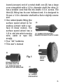
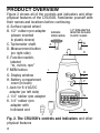
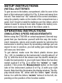
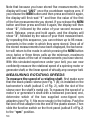
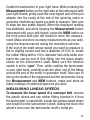
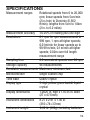
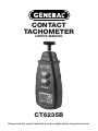
CONTACT
TACHOMETER
User’s ManUal
CT6235B
Please read this manual carefully and thoroughly before using this product.
TABLE OF CONTENTS
Introduction. . . . . . . . . . . . . . . . . . . . . . . . . 3
Key Features . . . . . . . . . . . . . . . . . . . . . . . . 4
Safety Instructions . . . . . . . . . . . . . . . . . . . 4
What’s in the Case . . . . . . . . . . . . . . . . 4 – 5
Product Overview . . . . . . . . . . . . . . . . . . . . 6
Setup Instructions. . . . . . . . . . . . . . . . . . . . 7
Install Batteries . . . . . . . . . . . . . . . . . . . . 7
Operating Instructions . . . . . . . . . . . . 7 – 12
Simulating Speed Measurements . . 7 – 10
Measuring Rotating Speeds . . . . . 10 – 11
Measuring Linear Speeds . . . . . . . 11 – 12
Measuring Surface Dimensions . . . . . . 12
Specifications . . . . . . . . . . . . . . . . . . 13 – 14
Maintenance Tips . . . . . . . . . . . . . . . . . . . 14
Warranty Information . . . . . . . . . . . . 14 – 15
Return For Repair Policy . . . . . . . . . . . . . . 15
2
INTRODUCTION
Thank you for purchasing General Tools & Instruments’
CT6235B Contact Tachometer. Please read this user’s manual
carefully and thoroughly before using the instrument.
The CT6235B is a general-purpose instrument that uses
dedicated fittings to measure—on contact—the speed of a
motor or generator’s rotating shaft and the linear speed of a
moving surface such as a conveyor belt or the circumference
of a wheel. The instrument also can be used as a ruler, to
measure the dimensions of stationary objects.
Measurements are displayed in real time on a 1 in. high backlit liquid-crystal display and stored in memory. Up to 96
measurements of rpm or linear speed can be stored, indexed
and recalled, along with the last value, the minimum value
and the maximum value of the series. Thanks to its five-digit
display, the tachometer can measure rotational speeds from
0 to 20,000 rpm, linear speeds from 5cm/min (2 in./min)
to 2km/min (6,562 ft./min), and lengths from 5cm to 10km
(2 in. to 6.2 miles).
The CT6235B is powered by four “AA” batteries (included)
or an optional 6V AC/DC adapter.
3
KEY FEATURES
• Uses contact measurement technique and autoranging
• Includes fittings for measuring the speed of a rotating
shaft and the linear speed of a conveyor
• Wide measurement range and high resolution
• Backlit 1 in. high display supports work in low light
• Stores and indexes up to 96 measurements
• Memorizes the last, minimum and maximum values of
a series of measurements
• Also measures any dimension of a stationary object,
in meters
• One-handed operation
• Auto power off function extends battery life
SAFETY INSTRUCTIONS
Spinning shafts and fast-moving conveyor belts can be
dangerous. When using the tachometer, take care not to let
your fingers, hands, hair or clothing make contact with moving parts.
WHAT’S IN THE CASE
The CT6235B comes fully assembled in a carrying case along
with the following accessories (see Figure 1):
• Three rubber fittings—called rpm adapters—for making
contact with the end of a rotating shaft of a motor or generator. Two have cone-shaped rubber tips that fit into a hol4
lowed (concave) end of a metal shaft; one (B) has a large
cone compatible with a 1/2 in. diameter shaft, the other (J)
has a smaller cone that fits into shafts 1/4 in. across. The
third (K) fitting has its own hollowed end; it is designed to
fit over a 1/4 in. diameter shaft with a flat or slightly convex
end.
• One rubber/plastic fitting (the
surface speed wheel A) for (B)
making contact with a surface in linear motion. The
surface speed wheel has a
1/8 in. slot into which moving 1/2" RUBBER RPM ADAPTER
wire, cable or rope fits INSERTED IN BLACK PLASTIC SLEEVE
snugly.
• Four “AA” batteries
• This user’s manual
(A)
(K)
Fig. 1
RPM ADAPTER WITH
HOLLOWED END FOR
1/4" DIAMETER SHAFTS
WITH FLAT OR CONVEX END
SURFACE
SPEED
WHEEL
(J)
1/4" RUBBER
RPM ADAPTER
5
PRODUCT OVERVIEW
Figure 2 shows all of the controls and indicators and other
physical features of the CT6235B. Familiarize yourself with
their names and locations before continuing.
A. Surface speed wheel
1/2" RPM ADAPTER
B. 1/2" rubber rpm adapter SURFACE
INSERTED IN BLACK
SPEED
WHEEL
PLASTIC SLEEVE
(shown inserted
in plastic sleeve)
B
C. Tachometer shaft
A
D. Measurement button
C
(on right side)
E. Function switch,
labeled
“m, m/min, rpm”
I
F. MEM button
D
G. Display window
E
H. Battery compartment
F
cover (in back)
I. Jack for 6-V AC/DC
adapter (on left side)
G
J. 1/4" rubber rpm adapter
K. 1/4" rubber rpm
adapter with
hollowed end
H
J
K
Fig. 2. The CT6235B’s controls and indicators and other
physical features
6
SETUP INSTRUCTIONS
INSTALL BATTERIES
To gain access to the battery compartment, slide its cover in the
back of the instrument (callout H of Fig. 2) down and away from
the unit. Then install four “AA” batteries in the correct orientation,
using the polarity marks on the inside of the compartment as a
guide. Don’t forget to install the batteries over the ribbon, which
makes it easier to remove them later. Replace the battery compartment cover, tucking the end of the ribbon under it.
OPERATING INSTRUCTIONS
SIMULATING SPEED MEASUREMENTS
Before using the CT6235B on actual equipment, General suggests that you familiarize yourself with the way the instrument measures, stores and recalls speeds by spinning the
tachometer’s shaft by hand. By simulating readings you can
expect to see in practice, you will safely gain expertise that
will save you time later.
To get started, make sure the black plastic sleeve (see
Fig. 1 (B) ) is installed on the tachometer’s shaft (callout C of
Fig. 2), with the slot of the sleeve over the shaft’s metal pin.
Cradle the tachometer in your right hand. Move the function
switch (callout E of Fig. 2) to either the “m/min” or “rpm”
position. Then press the Measurement button on the right
side of the instrument (callout D of Fig. 2) with your right
thumb. Note that this illuminates the display window. The display should show “0”, either with the letters “rpm” directly
below it or with the letters “m/min” below it to the left, depending on the position of the function switch.
7
To simulate a speed measurement, keep the tachometer
cradled in your right hand and spin its shaft by “flicking” it
with the middle two fingers on your left hand while pressing
the Measurement button with your right thumb. Note how
the display tracks the force of your flicks, and also how the
instrument powers off whenever the Measurement button
if released (this “dead man switch” feature extends battery
life considerably).
To simulate storing measurements, keep the Measurement button depressed with your right thumb while you
make three simulated speed measurements, as follows:
• Flick the shaft with your left index finger once. Store the
displayed reading by pressing the MEM button with your
left thumb.
• Flick the shaft again to make another simulated measurement. Store this reading by pressing the MEM button again.
• Flick the shaft a third time and store the third reading as
well by pressing the MEM button.
After simulating and storing three measurements, release
the Measurement button and do not press it again until instructed to.
To simulate recalling stored measurements, press the
MEM button once and hold it. This illuminates the display,
which now shows the highest of the three readings you have
just stored. Note that if you continue holding the MEM button,
the display alternates between showing
the highest value and the letters “UP”,
signifying the maximum speed.
8
Also note that releasing the MEM button powers off the display and the instrument.
Now press the MEM button twice and
hold it. This again illuminates the display,
but now it shows the last reading you
stored, indicated by and alternating with the letters “LA”.
Finally, press the MEM button three times and hold it. This
retrieves the slowest of the three speeds you measured and
stored. This value is shown alternating with the letters “dn”,
signifying the minimum speed.
To try out other memory-related features,
you can now press the Measurement
button on the right side. Now press the
MEM button once, twice and three times
(holding it in each time) and note from the display that all
three of your stored measurements have been erased (indicated by “0.0” readings for UP, dn and LA). You can confirm
this by pressing and holding the MEM button until the display
begins counting down from 20. When the count reaches 0,
the display immediately switches to showing the letters “AN”
on the left side and a number (in this case, “0”) on the right.
(The letters “AN” are an abbreviation for the Ancient Greek
word for “recall.”)
To complete this simulation exercise and put your new expertise to the test, make and store a set of five simulated measurements by hand-spinning the tachometer’s shaft and using
the MEM button. Then, remembering not to press the Measurement button, press and hold the MEM button as many
times as needed to make the display go into countdown mode.
9
Note that because you have stored five measurements, the
display will read “AN 5” once the countdown reaches zero. If
you release the MEM button and then press and hold it again,
the display will first read “1” and then the value of the first
of the five measurements you stored. If you release the MEM
button and then press and hold it again, the display will then
show “2”, followed by the value of your second measurement. Release, press and hold again, and the display will
show “3”, followed by the value of your third measurement.
By repeating this sequence, you can retrieve up to 96 measurements in the order in which they were stored. Once all of
the stored measurements have been displayed, the tachometer will return to the mode in which pressing the MEM button
once, twice or three times calls up the minimum, maximum
and last values of the set of measurements you have stored.
With this simulated experience under your belt, you can now
confidently measure the rotational speed of a spinning motor or
generator shaft, or the linear speed of virtually any conveyor belt.
MEASURING ROTATING SPEEDS
To measure the speed of a rotating shaft, first make sure
that the black plastic sleeve (see Fig. 1 (B)) is installed on the
tachometer’s shaft (callout C of Fig. 2), with the slot of the
sleeve over the shaft’s metal pin. To measure the speed of a
motor’s or generator’s shaft with a hollowed (concave) end,
determine which of the two supplied cone-tipped rpm
adapters (see Fig. 1) fits more snugly in the hollow. Push the
flat end of that adapter into the end of the plastic sleeve. Then
slide the function switch on the front panel (callout E of Fig.2)
to the “rpm” position.
10
Cradle the tachometer in your right hand. While pressing the
Measurement button on the right side of the instrument with
your right thumb, gently push the cone-tipped end of the rpm
adapter into the cavity at the end of the spinning motor or
generator shaft whose speed you wish to measure. Take care
to keep the two shafts aligned. When the displayed reading
has stabilized, and while keeping the Measurement button
depressed with your right thumb, press the MEM button on
the front panel with your left thumb to store the measurement. Make and store as many measurements as you wish,
using the lessons learned during the simulation exercise.
If the end of the shaft whose speed you want to measure is
flat or slightly convex and has a diameter of 0.25 in, locate
the rubber fitting with a 1/4 in. diameter hole at its wider end.
Insert the narrow end of this fitting into the black plastic
sleeve on the instrument’s shaft. Make sure the function
switch is set to “rpm”. Then, while cradling the tachometer
in your right hand, carefully push the other end of the fitting
around the end of the motor or generator shaft. Take care to
line up the shafts of the equipment and the tachometer. Using
the Measurement and MEM buttons, make and store as
many readings of rotational speed as you wish.
MEASURING LINEAR SPEEDS
To measure the linear speed of a conveyor belt, remove
the plastic sleeve and any rubber fitting inserted in it from
the tachometer’s metal shaft. Locate the surface speed wheel
and install it on the tachometer’s shaft, sliding the slot in the
wheel’s stem over the tachometer shaft’s metal pin.
11
Set the function switch to the “m/min” position. Then,
cradling the tachometer in your right hand, press the edge of
the surface wheel against the moving object whose linear
speed you wish to measure. Note that the circumference of
the wheel has a 1/8-in.-wide slot into which wire, cable or
rope of that diameter fits snugly.
Taking care to keep the tachometer perpendicular to the moving conveyor, use the function and MEM buttons to make and
store as many measurements of linear speed as you wish.
Linear speed measurements of moving objects obtained by
placing them in contact with the outer diameter of the surface
speed measurements are accurate as displayed. However, to
compensate for the smaller inner diameter of the wheel
within its slot, measurements made by placing wire, cable or
rope within the slot should be multiplied by 0.9.
MEASURING SURFACE DIMENSIONS
The CT6235B can also serve as a metric ruler. To operate it
in that mode, move the function switch to the “m” position
and install the surface speed wheel directly onto the instrument’s metal shaft.
Cradling the tachometer in your right hand and pressing and
holding the Measurement button, roll the wheel across
the length, width or depth of the object you wish to measure.
The displayed value represents the dimension measured, in
meters. Measurements made in this mode of operation cannot be stored, and disappear from the display when the
Measurement button is released.
12
SPECIFICATIONS
Measurement ranges
Rotational speeds from 0 to 20,000
rpm; linear speeds from 5cm/min
(2 in./min) to 2km/min (6,562
ft/min); lengths from 5cm to 10km
(2 in. to 6.2 miles)
Measurement accuracy ±0.05% of reading plus one digit
Resolutions
0.1 rpm for rpm measurements to
999 rpm, 1 rpm at higher speeds;
0.01m/min for linear speeds up to
99.99 m/min, 0.1m/min at higher
speeds; 0.02m over full length
measurement range
Sampling time
0.8 seconds at speeds over 60 rpm
Storage capacity
96 measurements
Recallable measurements Maximum, minimum, last
Microcontroller
Single custom chip
Time base
Quartz crystal
Display type
5-digit yellow-green backlit liquid
crystal
Display dimensions
1.0625 in. high x 1.8725 in. wide
(27 x 47.6mm)
Instrument dimensions 8.27 x 2.91 x 1.46 in.
(210×74×37mm)
Instrument weight
0.62 lb. (280g), including batteries
13
Power source
Four “AA” batteries or optional
6V AC/DC converter
Current consumption
65mA
Operating temperature range 32° to 122°F (0° to 50°C)
@ up to 80% relative humidity
MAINTENANCE TIPS
The CT6235B requires no regular maintenance other than
light cleaning of the housing and display with a soft, dry cloth.
When the text “LO” appears on the display, it’s time to
change the CT6235B’s four “AA” batteries because their total
potential has fallen below 4.5 volts. To do so, follow the Setup
Instructions on p. 7.
Remove the batteries whenever the instrument is expected
to sit idle for an extended period of time (six months or more).
WARRANTY INFORMATION
General Tools & Instruments’ (General’s) CT6235B Contact
Tachometer is warranted to the original purchaser to be free
from defects in material and workmanship for a period of one
year. Subject to certain restrictions, General will repair or
replace this instrument if, after examination, the company
determines it to be defective in material or workmanship.
This warranty does not apply to damages that General determines to be from an attempted repair by non-authorized
personnel or misuse, alterations, normal wear and tear, or
accidental damage. The defective unit must be returned to
14
General Tools & Instruments or to a General-authorized service center, freight prepaid and insured.
Acceptance of the exclusive repair and replacement remedies
described herein is a condition of the contract for purchase
of this product. In no event shall General be liable for any incidental, special, consequential or punitive damages, or for
any cost, attorneys’ fees, expenses, or losses alleged to be a
consequence of any damage due to failure of, or defect in
this product including, but not limited to, any claims for loss
of profits.
RETURN FOR REPAIR POLICY
Every effort has been made to provide you with a reliable
product of superior quality. However, in the event your instrument requires repair, please contact our Customer Service to
obtain an RGA (Return Goods Authorization) number before
forwarding the unit via prepaid freight to the attention of our
Service Center at this address:
General Tools & Instruments
80 White Street
New York, NY 10013
212-431-6100
Remember to include a copy of your proof of purchase, your
return address, and your phone number and/or e-mail
address.
15
GENERAL TOOLS & INSTRUMENTS
80 White Street
New York, NY 10013-3567
PHONE (212) 431-6100
FAX (212) 431-6499
TOLL FREE (800) 697-8665
e-mail: [email protected]
www.generaltools.com
CT6235B User’s Manual
Specifications subject to change without notice
©2011 GENERAL TOOLS & INSTRUMENTS
NOTICE - WE ARE NOT RESPONSIBLE
FOR TYPOGRAPHICAL ERRORS.
MAN#CT6235B 2/10/11