1
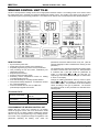
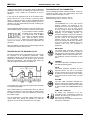
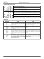
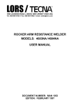
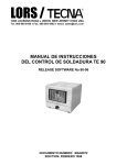
LORS / j 1090 LOUSONS ROAD ♦ UNION, NEW JERSEY 07083 USA Tel: 908-964-9100 ♦ Fax: 908-964-4492 ♦ email: [email protected] WELDING CONTROL UNIT TE-90 USER MANUAL RELEASE SOFTWARE No 90-06 DOCUMENT NUMBER: MAN4072 EDITION: FEBRUARY 1998 LORS / TECNA WELDER CONTROL UNIT: TE-90 This page is intentionally left blank. DOCUMENT NUMBER: MAN4072 EDITION: FEBRUARY 1998 Page 2 / 6 LORS / TECNA WELDER CONTROL UNIT: TE-90 WELDING CONTROL UNIT TE-90 TE-90 is a microprocessor welding control unit for single-phase resistance welders. The welding control unit is used to control the welder parts and, in particular, the thyristors adjusting the welding current. The working cycle carried out by the TE-90 is described through the programming parameters. The TE-90 can be used for both manual and pneumatic-operated welders. MAIN FEATURES Synchronous thyristor drive. Phase shift control for welding current adjustment. Simplified programming by means of four push-buttons. Twin pre-setting for time and current, recallable by two independent controls. Slope and pulse functions. Single and repeat operating mode. Secondary current compensation function for welding of oxidized sheets and rods. Auto-retain disabling for manually operated welders. First phase shift delay adjustment. It enables the machine line current best balance. Control of solenoid valve 24 Vdc 7,2 W Max with protected output against short circuits. TECHNICAL DATA Electronic circuit supply: 24 Vdc +10% / -20% 50/60 Hz. Consumption: 7 VA at rest 21 VA when welding Operative temperature: 5 ÷ 40 °C PROGRAMMING THE WELDING CONTROL UNIT Straight after the control unit is switched on, the display shows the program version; after a few seconds the TE-90 equipment is set in a waiting condition enabling the operator either to carry out the programming or any welding process. The control unit is programmed through the regulation of all parameters describing the welding cycle; select the DOCUMENT NUMBER: MAN4072 parameters and set the desired values one by one. (See the relevant paragraph to better understand the meaning of each parameter.) The parameters are marked with international symbols which are listed on the left side of the control unit. Each parameter is combined with a pilot light. Select the parameters by means of push-buttons d and f , the pilot light corresponding to the selected parameter lights on and its value is shown on the display. Change the welding parameters value by means of pushbuttons a and s , thus increasing or decreasing the value shown on the display. The parameters can be set to different values, according to the type of parameter. The minimum and maximum limits of each parameter are described in the following table. PARAMETER SQUEEZE WELD TIME CURRENT HOLD OFF TIME COMPUTER OFF/COMPUTER ON SINGLE/REPEAT WELD TIME 2 CURRENT 2 SLOPE COLD IMPULSE NUMBER EDITION: FEBRUARY 1998 RANGE 1-99 cycles 1-99 cycles * 1-99% 1-99 cycles 1-99 cycles 00-01 00-01 0-99 cycles * 0-99% 0-29 cycles 1-50 cycles 0-9 Page 3 / 6 LORS / TECNA WELDER CONTROL UNIT: TE-90 * When the pulse function is used, that is when the IMPULSE NUMBER is other than 0, the welding time should not exceed 25 periods. If this condition is not observed, an error is signaled. DESCRIPTION OF THE PARAMETERS In this way all the parameters are set to the desired value. Please notice that it is not necessary to press any pushbutton to confirm the set value, as this is automatically stored up after the adjustment. When programming step is over, it is possible to use the welder without previously confirming the set or the stored data. Mains frequency of 50 Hz 1 period = 20 ms Mains frequency of 60 Hz 1 period = 16,6 ms Use the WELD/NO WELD function to carry out any test cycle without welding current. By means of the here shown proper key, it is possible to enable or disable the welding current. When the light is on, the control unit is set to WELD and it carries out standard welding cycles. When the light is off, the complete test cycles without welding current, even though all the time-relevant parameters are preserved. During the welding cycle the control unit shall display both the current function and the relevant value. DESCRIPTION OF THE WORKING CYCLE The TE 90 working cycle is described by the user through the regulation of all programming parameters. These parameters indicate the operating times and the current adjustments characterizing the working cycles whenever performed consecutively. The following chart shows the order the programmed functions are carried out. All the following parameters indicating a period of time are expressed in mains cycles, also called periods. The mains frequency defines the length of a cycle: SQUEEZE The SQUEEZE time is the time interval elapsing between the beginning of the electrode movement and the beginning of the welding cycle. The set value should be long enough to allow the electrodes to reach the correct tightening force before the beginning of the welding process. An insufficient regulation of this time causes the formation of flashes between the electrodes and the sheet at the beginning of the welding process; this inconvenient could lead to an unsteady quality level. Should the cycle start signal be disabled during the squeeze time, then the sequence is interrupted. WELD TIME The WELD TIME parameter indicates the current flow duration. It will be carried out with the power value indicated in parameter CURRENT. When the pulse operation is on, this parameter signals the duration of each pulse. CURRENT The value expressed in CURRENT indicates the welding operating power. HOLD The HOLD parameter describes the time elapsing between the end of the welding process and the opening of the electrodes. It enables a shorter cooling of the welding spot and avoids its stress before a proper cooling. The symbols refer to the programming parameters described in the following paragraph. Due to safety reasons, the microprocessor does not start the welding cycle when the cycle start signal is enabled during the welder connection; in this case, disable the control and then enable it again. Any micro-interrupts or excessive voltage drops block the control, rather than altering the operation; to reset the operation, turn the machine off and then turn it on again. DOCUMENT NUMBER: MAN4072 OFF TIME The OFF TIME parameter describes the machine waiting time elapsing between one machine cycle and the other when the welder is used in repeat mode (SINGLE/REPEAT set to 01). COMP. OFF / COMP. ON By setting this parameter to 01 the secondary current compensation function is enabled. By setting the parameter to 00 the function is disabled. When working, the relevant led shows that this function is activated. EDITION: FEBRUARY 1998 Page 4 / 6 LORS / TECNA WELDER CONTROL UNIT: TE-90 SINGLE / REPEAT By setting this parameter to 00 the machine will operate in SINGLE mode: the control unit carries out only one welding cycle whenever a cycle start signal has been received. By setting this parameter to 01 the machine will operate in REPEAT mode: the welder will go on carries out welding cycles until the cycle start signal is released. Welding cycles are repeated with a time interval as defined in parameter OFF TIME. When working, the relevant led shows that REPEAT mode is activated. WELD TIME 2 Should the cycle be enabled with the cycle start signal START 2 (by means of either a second foot control or a proper selector) the control unit carries it out considering this welding time adjustment instead of the one set in the WELD TIME parameter. If this time is set to zero, then the control unit will carry out the welding cycle following the main parameters. CURRENT 2 The CURRENT 2 parameter indicates the welding power adjustment whenever the cycle has been carried out starting from the second start of cycle signal START 2. If this parameter is set to zero, the control unit will perform the welding cycle following the main parameters. SLOPE The SLOPE parameter describes the time used to reach the programmed welding current. The initial value of this slope always corresponds to the minimum current value, while the final value corresponds to the current value programmed in parameter CURRENT or CURRENT 2. The slope of this parameter is automatically calculated by the microprocessor according to the programmed values. COLD The COLD parameter is used in the pulse operating mode and indicates the time elapsing between one welding pulse and the next one. IMPULSE NUMBER The IMPULSE NUMBER parameter indicates the number of impulses used to carry out the welding process. When this parameter is set to 0, the pulse operation is disabled. The length of each impulse corresponds to the time set in the WELD TIME or WELD TIME 2 parameter. When working, the relevant led shows that this function is activated. DOCUMENT NUMBER: MAN4072 COMPENSATION FUNCTION OF SECONDARY CURRENT The compensation function of secondary current is used to facilitate the welding process of oxidized sheets and rods. The pieces oxidation blocks the current flow during the first welding phase, thus limiting, in a different way depending from the welding process, the real time of current flow. The compensation function controls the welding current by means of a coil located inside the secondary circuit. Until the welding current does not exceed a pre-set limit, the welding time is automatically extended up to a limit of 99 cycles. In this way it is possible to carry out welding processes with an always constant real time of current flow. If, after having reached the 99 welding periods limit, the current limit is not exceeded, the control unit will indicate that the welding process has not been correctly carried out by displaying the E4 error, and will block the welder functioning. To restore the functioning, press a push-button. The current limit is adjusted, by means of an internal trimmer, by the welder manufacturer. The standard value is usually about 1500=2000 A. By means of JP2 jumper, located on the card, is possible to disable this function: COMPENSATION ON OFF JUMPER JP2 OPEN CLOSED DELAY FUNCTION OF FIRST PHASE SHIFT This function allows to obtain the best machine line current balance. Simultaneously press push-buttons d and f for about one second to carry out the adjustment. The CURRENT function lamp flashes and the display shows the actual set value. As usual, the adjustment is carried out by pressing push-buttons a and s . The value can be set from 35 up to 99. When the programming is over, press d or f . As this adjustment is carried out by the welder manufacturer, the user does not need to modify this value. AUTO-RETAIN FUNCTION As usual, when the current flow starts, the welding control unit ends the welding cycle even if the cycle start control is disabled. This function is called auto-retain function. In TE 90 it can be disabled to use the control unit for manual-operated welders. In this case, if the cycle start signal is disabled during the machine cycle, the control unit will immediately stop the welding current flow and disconnects the solenoid valve. In both cases the control unit immediately stops the cycle and opens again the electrodes whenever the cycle start signal is disabled during the squeeze phase. The autoretain function selection is carried out through jumper JP1 located on the card: AUTORETAIN ON OFF JUMPER JP1 CLOSED OPEN While using electric-operated welders this function should always be enabled in order to prevent any welding cycle from having a welding time other than the set one. EDITION: FEBRUARY 1998 Page 5 / 6 LORS / TECNA WELDER CONTROL UNIT: TE-90 CONTROL PANEL PILOT LIGHTS It signals that the mains voltage is on. It signals that the main cycle start control is on. It signals that the additional cycle start control is on. It signals that the block control with pressure only is on. This input is activated by the first stage of a foot control or by other devices that should hinder the welding process (such as for example, flow switches, pressure switches or the interlocking system of another welder). It signals that the control unit is generating the control impulses for SCR. It signals that the solenoid valve is on. ERROR LIST MESSAGE CAUSE CURE The value of one of the stored parameters exceeds the preset limits. This could be caused by a loss of data due to any interference or wrong functioning. Press a push-button to cancel the error. Check all the values set in the parameters and correct them if necessary. Apply to the after-sale service if the trouble occurs frequently. The welding time is set to a value higher than 25 and pulses operating mode is activated. This parameter cannot be higher than 25 in the pulse mode operation. Press a push-button to cancel the error. Set the welding time to a value lower or equal to 25 cycles. Pulses operating mode is activated and the total welding time (welding time x impulse number) is higher than the limit of 150 cycles. Do not exceed this value so as not to overheat the machine. Press a push-button to cancel the error. Decrease the welding time or the impulse number so that their product is lower than 150 cycles. The compensation function is enabled and the control unit has extended the welding time up to the maximum limit of 99 periods. The set welding time has not been carried out with a welding current higher than the limit. Press a push-button to cancel the error. Before restart the welding process check the welding conditions. If the pieces are too oxidized they must be cleaned. DOCUMENT NUMBER: MAN4072 EDITION: FEBRUARY 1998 Page 6 / 6