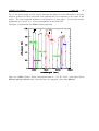
1
European Organisation for Astronomical Research in the Southern Hemisphere Organisation Européenne pour des Recherches Astronomiques dans l’Hémisphère Austral Europäische Organisation für astronomische Forschung in der südlichen Hemisphäre VERY LARGE TELESCOPE HAWK-I User Manual Doc. No.: VLT-MAN-ESO-22200-6281 Issue: 1 Date: 04.03.2015 Function Author Name Elena Valenti Job Manager Jerome Paufique PS Harald Kuntschner PM Robin Arsenault Date Signature AOF Releaser Norbert Hubin Luca Pasquini This document is under configuration control ESO, Karl-Schwarzschild-Str. 2, 85748 Garching bei München, Germany Doc: Issue: 1 Date:4/3/15 Page:2 of 50 HAWK-I User Manual VLT-MAN-ESO-22200-6281 CO-AUTHORS Co-Authors Ralf Siebenmorgen HAWK-I IOT Affiliation, Division ESO, INS ESO REVIEWERS Reviewers Giovanni Carraro Affiliation, Division ESO, LPO CHANGE RECORD ISSUE 1 DATE 04.03.15 SECTION/PARA. AFFECTED All REASON/INITIATION DOCUMENTS/REMARKS Initial draft HAWK-I User Manual Issue 1 HAWK-I and GRAAL attached to the VLT and GRAAL in the integration hall in Garching HAWK-I in a Nutshell Online information on HAWK-I can be found on the instrument web pages, in Casali et al. 2006, and in Kissler-Patig et al. 2008. HAWK-I is a near-infrared (0.85 2.5 µm) wide-field imager. The instrument is cryogenic (120 K, detectors at 75 K) and has a full reflective design. The light passes four mirrors and two filter wheels before hitting a mosaic of four Hawaii 2RG 2048⇥2048 pixels detectors. The final F-ratio is F/4.36 (100 on the sky correspond to 169.4µm). The field of view (FoV) on the sky is 7.50 ⇥7.50 (with a small cross-shaped gap of ⇠ 1500 between the four detectors). The pixel scale is 0.10600 /pix . The two filter wheels of six positions each host ten filters: Y, J, H, Ks (identical to the VISTA filters), as well as 6 narrow band filters (Br , CH4, H2 and four cosmological filters at 0.984, 1.061, 1.187, and 2.090 µm). Typical limiting magnitudes (S/N=5 in 3600s on source) are around J= 23.9, H= 22.5 and Ks = 22.3 mag (Vega). HAWK-I can be used in combination with the GRound layer Adaptive optics system Assisted by Lasers (GRAAL), a seeing improver, whose ultimate goal is to enhance the instrument image quality. Under most seeing conditions (100 in visible band), with the use of 4 lasers and a natural star for atmospheric and telescope tip-tilt correction GRAAL reduces the 50% encircled energy diameter by 12% in the Y and 21% in the Ks filters, respectively, over the entire FoV. That is, the FWHM of the PSF is typically reduced from 0.5300 to 0.4200 in Ks band. The visible tip-tilt star (7 < R < 14.5) is acquired outside the instrument FoV to avoid obscuration, therefore it must be located between 6.70 and 7.70 FoV. For best correction, the star should be brighter than R⇠ 14 mag (TBD). However, GRAAL can work with stars as faint as R⇠ 18 mag but in the best seeing conditions (TBD). Observations with GRAAL require PHO or CLR conditions (THN is to be still verified). i HAWK-I User Manual Issue 1 ii . . . . . . . . 1 1 1 1 2 2 2 2 3 Contents 1 Introduction 1.1 Science drivers . . . . . . . 1.2 Scope of this document . . 1.3 Structure of this document 1.4 More important information 1.5 Contact information . . . . 1.6 News . . . . . . . . . . . . 1.7 Glossary . . . . . . . . . . 1.8 Abbreviations and Acronyms I . . . . . . . . . . . . . . . . . . . . . . . . . . . . . . . . . . . . . . . . . . . . . . . . . . . . . . . . . . . . . . . . . . . . . . . . . . . . . . . . . . . . . . . . . . . . . . . . . . . . . . . . . . . . . . . . . . . . . . . . . . . . . . . . . . . . . . . . . . . . . . . . . . . . . . . . . . . . . . . . . . . . . . . . . . . . . . . . . . . . . . . . . . . . . . . . . . . . . . . . . . . . . . . . . . . . . . . . . . . . . . . . The instrument 4 2 Cold part: the imager 2.1 Optics . . . . . . . . . . . . . . . . . . . . . . . . . . . . . . . . . . . . . . . . 2.2 Mechanics . . . . . . . . . . . . . . . . . . . . . . . . . . . . . . . . . . . . . . 2.3 Detectors . . . . . . . . . . . . . . . . . . . . . . . . . . . . . . . . . . . . . . . 4 4 5 5 3 Warm part: the ground layer adaptive optics system 3.1 Introduction . . . . . . . . . . . . . . . . . . . . . 3.1.1 Atmospheric Turbulence . . . . . . . . . . . 3.1.2 Ground Layer Adaptive Optics . . . . . . . . 3.2 Design of the module . . . . . . . . . . . . . . . . 3.3 Wavefront sensors . . . . . . . . . . . . . . . . . . 5 6 6 6 7 8 II . . . . . . . . . . . . . . . . . . . . . . . . . . . . . . . . . . . . . . . . . . . . . . . . . . . . . . . . . . . . . . . . . . . . . . . . . . . . . . . . Instrument Performance 10 4 Detectors 4.1 Threshold-limited integration . . . . . . . . . . . . . . . . . . . . . . . . . . . . 10 11 5 Field of view 5.1 Relative position of the four quadrants . . . . . . . . . . . . . . . . . . . . . . . 5.2 Center of Rotation and Centre of Pointing . . . . . . . . . . . . . . . . . . . . . 5.3 Vignetting of the FoV . . . . . . . . . . . . . . . . . . . . . . . . . . . . . . . . 11 12 13 13 6 Filters 14 7 TT star properties 14 8 Limiting magnitudes 14 HAWK-I User Manual Issue 1 iii 9 Image quality and astrometry 15 III 16 Observing with HAWK-I: from phase 1 to data reduction 10 Introduction 16 11 Phase 1: applying for observing time with HAWK-I 11.1 Getting reasonable photometry with HAWK-I . . . . 11.1.1 Consider the 2MASS calibration fields . . . . 11.1.2 HAWK-I extinction coefficients . . . . . . . 11.2 The Exposure Time Calculator . . . . . . . . . . . 11.3 Proposal Form . . . . . . . . . . . . . . . . . . . . 11.4 Overheads and Calibration Plan . . . . . . . . . . . . . . . . . 16 16 17 17 17 18 19 . . . . . 20 20 20 21 21 22 . . . . . . . 24 24 24 24 24 25 26 26 12 Phase 2: preparing your HAWK-I observations 12.1 HAWK-I specifics to templates, OBs, and p2pp 12.1.1 p2pp and the GuideCam tools . . . . . 12.1.2 Observing Blocks – OBs . . . . . . . . 12.1.3 Templates . . . . . . . . . . . . . . . 12.2 Finding Charts and README Files . . . . . . . . . . . . . . . . 13 Observing strategies with HAWK-I 13.1 Overview . . . . . . . . . . . . . . . . . . . . . . 13.2 Visitor Mode Operations . . . . . . . . . . . . . . 13.3 The influence of the Moon . . . . . . . . . . . . . 13.4 Twilight . . . . . . . . . . . . . . . . . . . . . . 13.5 Orientation, o↵set conventions and definitions . . 13.6 Instrument and telescope overheads . . . . . . . . 13.7 Recommended DIT/NDIT and Object–Sky pattern IV . . . . . . . . . . . . . . . . . . . . . . . . . . . . . . . . . . . . . . . . . . . . . . . . . . . . . . . . . . . . . . . . . . . . . . . . . . . . . . . . . . . . . . . . . . . . . . . . . . . . . . . . . . . . . . . . . . . . . . . . . . . . . . . . . . . . . . . . . . . . . . . . . . . . . . . . . . . . . . . . . . . . . . . . . . . . . . . . . . . . . . . . . . . . . . . . . . . . . . . . . . . . . . . . . . . . . . . . . . . . . . . . . . . . . . . . . . . . . . . . . . . . . . . . . . . . . . . . . . . . . . . . . . . . . . . . . . . . . . . . . . Reference Material 29 A Detectors A.1 Structures and features . . . . . . . . . . . . . . . . . . . . . . . . . . . . . . . A.2 Relative sensitivity . . . . . . . . . . . . . . . . . . . . . . . . . . . . . . . . . . 29 29 30 B The HAWK-I filters 33 C The C.1 C.2 C.3 35 35 35 35 HAWK-I calibration plan Do you need special calibrations? . . . . . . . . . . . . . . . . . . . . . . . . . . The HAWK-I standard calibrations in a nutshell . . . . . . . . . . . . . . . . . . . Quality Control . . . . . . . . . . . . . . . . . . . . . . . . . . . . . . . . . . . . HAWK-I User Manual D HAWK-I Burst and Fast Jitter Modes D.1 Description . . . . . . . . . . . . . . . . . . . . . . . . . . . D.2 Implementation . . . . . . . . . . . . . . . . . . . . . . . . D.2.1 Detector Windowing . . . . . . . . . . . . . . . . . . D.2.2 Data Products and Cube Sizes . . . . . . . . . . . . D.2.3 Minimum DIT, Overheads, and Frame Losses . . . . . D.3 Preparation and Observation . . . . . . . . . . . . . . . . . . D.3.1 OB Naming Convention . . . . . . . . . . . . . . . . D.3.2 OB Requirements and Finding Charts . . . . . . . . . D.3.3 Observing Modes . . . . . . . . . . . . . . . . . . . D.3.4 Calibration Plan . . . . . . . . . . . . . . . . . . . . D.3.5 FITS Files Names . . . . . . . . . . . . . . . . . . . D.4 Template Guide . . . . . . . . . . . . . . . . . . . . . . . . D.4.1 Acquisition: HAWKI img acq FastPhotNoAOF . . . . D.4.2 Acquisition: HAWKI img acq FastPhotAOF . . . . . . D.4.3 Science template: HAWKI img obs FastPhot . . . . . D.4.4 Calibration templates: HAWKI img cal DarksFastPhot Issue 1 . . . . . . . . . . . . . . . . . . . . . . . . . . . . . . . . . . . . . . . . . . . . . . . . . . . . . . . . . . . . . . . . . . . . . . . . . . . . . . . . . . . . . . . . . . . . . . . . . . . . . . . . . . . . . . . . . . . . . . . . . . . . . . . . . . . . . . . . . . . . . . . . iv . . . . . . . . . . . . . . . . . . . . . . . . . . . . . . . . 37 37 38 39 40 43 45 45 45 45 46 46 46 46 48 48 49 HAWK-I User Manual 1 Issue 1 1 Introduction HAWK-I does only one thing, but it does it well: direct imaging in the NIR (0.97 to 2.31 µm) over a large field (7.5’⇥7.5’). It can be used in seeing limited mode, but also it can make use of ground layer adaptive optics (GRAAL) achieved through a deformable secondary mirror and the laser guide stars facility. 1.1 Science drivers So far HAWK-I has been successfully used to study: • the properties of medium redshift galaxy clusters (see e.g. Lidman et al. 2008, A&A 489,981) • the outer solar system bodies (see e.g. Snodgrass et al. 2010, A&A 511, 72), • the very high redshift universe (see e.g. Castellano et al. 2010, A&A 511, 20), • exo-planets (see e.g. Gillon et al. 2009, A&A 506, 359), • the properties of Galactic stellar populations (see e.g. Valenti et al. 2013, A&A, 559, 98) and star-forming regions (see e.g. Preibish et al. 2011, A&A, 530, 34) The relatively recent implementation of Fast Photometry (see Appendix F) is probably going to boost more activity in the exo-planets field, as well as in the study of crowded fields through holographic imaging technique (see Schoedel et al. 2013, MNRAS, 249, 1367) 1.2 Scope of this document The HAWK-I user manual provides a description of the instrument characteristics, as well as information required for the proposal (Phase 1) and the observation (Phase 2 ) preparation. Guidelines for the post-observation phase are also summarised. The instrument has started regular operations in period 81 operating exclusively in seeing limited mode until period XX. Afterwards, with the installation on UT4 of the Adaptive Optics Facility (AOF) the instrument has been equipped with GRAAL, a seeing improver allowing to enhance the instrument image quality. We welcome any comments and suggestions on the present manual; these should be addressed to our user support group at [email protected]. 1.3 Structure of this document The document is structured as follows: • Part I provides a technical description of HAWK-I and GRAAL; • Part II details the instrument performance; • Part III describes the commonly used observing technique in the IR and provides guidelines for Phase 1 and Phase 2 preparation; • Part IV contains collected useful reference material. HAWK-I User Manual 1.4 Issue 1 2 More important information A handful of things that you must remember are: • The TT star has to be fainter than R=7; • Phase 1 constraints are binding. Because the use of the lasers requires CLR or PHO conditions, check in advance the presence of suitable TT -star(s); All HAWK-I related manuals are available on the HAWK-I instrument web page together with the most updated information of the instrument. For both Service and Visitor mode Observing Block (OBs) should be prepared with the latest version of the Phase 2 Proposal Preparation tool (p2pp). Information on the preparation of Service mode observation with HAWK-I can be found here. Visiting astronomers do not need to submit OBs in advance of their observations. However, they should prepared them before arriving at the observatory or, at latest, at the observatory the nights before their observing run. They will find further instructions on the the Paranal Science Operations web page and the Paranal Observatory home page. In particular, visiting astronomers are strongly encouraged to read this page. 1.5 Contact information In case of specific questions related to Service Mode observations, the use of the pipeline, and the proposal preparation (Phase 1) please contact the ESO User Support Department. For general information on Visitor Mode observations please contact the Paranal Science Operation Team. 1.6 News Please recall that the most up-to-date information on the instrument can be found on the HAWK-I news web page. 1.7 Glossary Active Optics: This is the active control of the primary mirror of the telescope. It is performed by using a telescope guide star. Adaptive Optics: This is the correction of the wavefront errors induced by atmospheric turbulence. The wavefront is measured from laser spots and the corresponding corrections are sent to the deformable secondary mirror. Laser Guide Star: The artificial star created by the sodium laser at an altitude of ⇠80-100 km. Titp-Til Star: The star used to sense and correct the tip-tilt aberrations, which are not sensed by the lasers. HAWK-I User Manual 1.8 Abbreviations and Acronyms 2MASS 4LGS AO AOF DIT DMO DSM ESO ETC FC FoV FWHM GLAO GRAAL HAWK-I NDIT NGS NIR OB P2PP PSF QC RTC RTD SM TT TIO USD UT VLT VM WF WFS Two Micron All Sky Survey 4 Laser Guide Stars Adaptive Optics Adaptive Optics Facility Detector Integration Time Data Management and Operations Division Deformable Secondary Mirror European Southern Observatory Exposure Time Calculator Finding Chart Field of View Full Width at Half Maximum Ground Layer Adaptive Optics GRound layer Adaptive optics system Assisted by Lasers High Acuity Wide-field K-band Imager Number of Detector Integration Time Natural Guide Star Near InfraRed Observing Block Phase II Proposal Preparation Point Spread Function Quality Control Real Time Computer Real Time Display Service Mode Tip-Tilt Telescope and Instrument Operator User Support Department Unit Telescope Very Large Telescope Visitor Mode WaveFront WaveFront Sensor Issue 1 3 HAWK-I User Manual Issue XX 4 Part I The instrument 2 Cold part: the imager The HAWK-I instrument design is presented by Casali et al. 2006, and Kissler-Patig et al. 2008; a summary is provided in the following subsections. Figure 1: Cut through HAWK-I for an optical and mechanical overview. Blue: optical components; black: cold assembly, filter wheels, detector assembly; green: radiation shield; red: vessel structure, cryogenic components, electronic rack. 2.1 Optics The optical layout of HAWK-I is given in Fig. 2. The entrance window of the vacuum vessel is Figure 2: HAWK-I optical layout used to image the pupil on the M3 mirror. A cold ba✏e stops the light outside of the instrument FoV. The first folding mirror (M1) is used for beam accommodation. Then the camera consists of one large spherical mirror M2 and two aspherical mirrors M3 and M4 allowing to adapt the HAWK-I User Manual Issue XX 5 telescope beam to the required F/4.36. The two filter wheels are located directly in front of the detector mosaic. The size of the filter needed to cover the whole FoV is 105⇥105 mm. The beam incidence angle versus the filter is quasi constant for all points of the field to keep the spectral filtering uniform over the whole FoV. 2.2 Mechanics HAWK-I is installed at the Nasmyth A of VLT-UT4 (Yepun), and centred on the Nasmyth adaptor by the interface flange. The vacuum vessel is split into three elements: i) vessel from part, which extends to the interface flange diameter; ii) vessel centre part, which o↵ers all necessary supply ports and mechanical connections to support the cold mechanics; iii) access to the detector, filter unit, filter exchange, the connection of the closed cycle coolers, pre-cooling lines and electronically cables. 2.3 Detectors The HAWK-I detector mosaic (see Fig. 3) is composed of four 2 k⇥2 k Hawaii 2RG arrays with 2.5 µm cuto↵. Figure 3: HAWK-I detector mount 3 Warm part: the ground layer adaptive optics system GRAAL, the ground layer adaptive optics system of HAWK-I is presented and discussed in Paufique et al 2010 and Paufique et al. 2012. The adaptive correction (AO) is provided by the deformable secondary mirror (DSM), nearly conjugated with the ground layers of the atmosphere, at ⇠90 m. Therefore GRAAL is able to compensate for the lowest layers of the atmospheric turbulence (up to 1 km, depending on the spatial frequencies considered), carrying more than half of the turbulence variance. GRAAL is a seeing improver, and does not provide di↵raction limited images at the focal plane. To highlight the advantage of HAWK-I User Manual Issue XX 6 combining GRAAL with HAWK-I a PSF is shown in Fig. 4 in AO open-loop (uncorrected) and a close-loop. Figure 4: Simulated PSF without (left) and with (right) GRAAL correction. 3.1 Introduction The following section provides an introduction to the field of atmospheric turbulence, and it is essentially taken from the NACO user manual. For further reading, see for example Adaptive Optics in astronomy, Rodier 1999, Cambridge University Press, or Introduction to adaptive optics, Tyson 2000, Bellinghan/SPIE. 3.1.1 Atmospheric Turbulence The VLT theoretical di↵raction limit is 1.22⇥ /D=0.700 at = 2.2µm. However, the resolution is severely limited by the atmospheric turbulence to /r0 ⇠100 , where r0 is the Fried parameter. r0 is directly linked to the strength of the turbulence and it depends on the wavelength as 6/5 . For average observing conditions, r0 is typically 60 cm at 2.2 µm. Temperature inhomegeneities in the atmospheric induce temporal and spatial fluctuations in the air refractive index and therefore cause fluctuations in the optical path. This leads to random phase delay that corrugate the wavefront. The path di↵erences are, to a good approximation, achromatic. Only the phase of the wavefront (WF) is chromatic. The coherence time of the WF distortions is related to the average wind speed V in the atmosphere and is typically of the order of r0 /V = 60 ms at 2.2 µm for V = 10 m/s. 3.1.2 Ground Layer Adaptive Optics A technique to overcome the degrading e↵ects of the atmospheric turbulence is real-time compensation of the deformation of the WF by AO. Very schematically, the wavefront sensor (WFS) measures the WF distortions, which are processed by the real-time computer (RTC). The RTC controls a deformable mirror to compensate the WF distortions. A particular type of AO systems is the ground layer adaptive optics (GLAO), which relies on the correction of the lowest layers of the atmospheric turbulence to improve the image quality delivered to astronomical observations. A practical implementation of this type of AO faces numerous difficulties. Indeed, in contrast with classical on-axis AO, GLAO requires excluding the highest layers of the atmosphere from the correction brought by the system. This can be done by using i) Rayleight guide-star, for limited telescope diameters, or ii) with multiple Na-Laser guide star, for HAWK-I User Manual Issue XX 7 larger telescopes. The combination of powerful laser sources at the Na wavelength and low noise fast detectors makes possible today to implement GLAO systems on 8 m-class telescope. 3.2 Design of the module GRAAL is the widest FoV GLAO system developed for an 8-m class telescope, with a free-from optics scientific FoV of over 10.50 . Its sky coverage exceeds 95%, and allows 100% sky coverage with a slightly limited performance. GRAAL o↵ers an improvement of about 40% on the K-band FWHM, allowing routine observations with 0.3 FWHM (50% of the time with a seeing in the line of sight of 0.95). This represents a factor 2 with respect to the current situation, where worse seeing conditions are used more often by HAWK-I than by the AO instruments MUSE (in narrow field mode) and SINFONI, located on other foci of the same telescope. It also allows using the full potential of HAWK-I and its sampling of 0.100 per pixel. The UTs of the Paranal observatory have been designed such as to minimize the non-atmospheric sources of image degradation, with for instance a closed-loop active optics during science observations. GRAAL therefore only correct further these disturbances at higher temporal frequencies, excepted in the case of very good seeing, where the telescope and enclosure residual seeing contributions might become significant in the PSF formation. Figure 5: GRAAL focal plane illustration. The 4 LGS rotate with respect to the FoV. The visible TT-star is selected outside of the LGS ring. The cones represent the Rayleight scattering areas from upwards propagation of the laser beams (lasers are side-launched). GRAAL is based on a 4 Na-LGS (sodium Laser Guide-Stars) system, launched from the corners of the centrepiece of UT4. As shown in Fig. 5, the lasers are pointed towards areas located outside of the science FoV (7.50 ⇥7.50 ), and the light re-emitted by the 80-100 km altitude Sodium layer is collected by 4 WFS each with 40⇥40 subapertures. The slopes provided by the WFS are combined to provide an estimate of the WF error for the lowest layers; this shape is then removed from the actual shape of the DSM. The AO-loop is closed at a 700 to 1000 Hz frequency. As the LGS are not useful to sense Tip-Tilt (TT), an additional visible Natural guide-star (NGS) HAWK-I User Manual Issue XX 8 WFS is embedded in GRAAL, and the TT is corrected at a loop frequency of 250 Hz. The science HAWAII 2RG infrared sensors of HAWK-I is as well used to correct slow drifts between visible WFS and IR imaging paths, coming from flexures and uncompensated atmospheric dispersion, taking the opportunity of continuous reading of the science detectors during integration. HAWK-I uses the adapter/rotator of the Nasmyth focus to derotate its FoV. On the opposite, GRAAL LGS-WFS must derotate the pupil; therefore GRAAL includes an LGS-ring, a derotator carrying the LGS-WFS, which counteracts the adapter’s e↵ect (to which is added the pupil rotation, proportionnal to the elevation of the telescope). Therefore, to summarise GRAAL science mode is based on the use of: • 4 LGS projected on-sky with the help of 4 dedicated launched telescopes • The corresponding WFS located on a 120 diameter ring, • one TT sensor using a NGS on a 14.50 ring • truth sensing is realized by the telescope guide-probes, a 21x21 Shack-Hartmann sensor already in operation in Paranal since the telescope installation for active optics control. Note that the active optics control will be superseded by the fast AO loop, so that the active optics sensor will be blind to all modes but the ones invisible to the AO system, the first of them being the focus mode • SPARTA, an RTC platform sharing commonalities of hardware and software design with other AO systems (GALACSI and SPHERE) and • the DSM LGS-TTs are filtered out and sent to the LGS launch systems to correct the jitter of each beam independently. Slopes computed from each of the four LGS WFS at the loop rate (1000 Hz) are split in two components, respectively TT and high orders, commands are then used to drive the LGS jitter actuators, respectively the DSM. 3.3 Wavefront sensors The LGS sensor unit consists of 4 identical systems. Each one is composed of: • One small pick-up mirror placed with a fixed arm at 5.800 from the optical axis on the Nasmyth focal plane • One trombone allowing focusing on the LGS • One re-imaging objective composed of two lenses • One 40⇥40 micro lenses array • One 240⇥240 L3 CCD and NGC controller Each pick-up mirror redirects the LGS light to a classical Shack-Hartmann WFS. The system accepts focus variations from 80 to 180 km. The visible TT sensor collects the the light of a NGS before the Nasmyth focal plane outside the HAWK-I FoV. A pick-up mirror selects the NGS inside a FoV ring internal radius of 6.60 and external radius 7.60 . The system is composed of: HAWK-I User Manual • One pick-up mirror with at least 5000 FoV • One re-imaging objective • One 240⇥240 CCD Issue XX 9 HAWK-I User Manual Issue XX 10 Part II Instrument Performance 4 Detectors The naming convention for the four detectors is shown in Figure 4. Note that quadrant 1,2,3,4 are usually, but not necessarily, stored in extensions 1,2,4,3 of the HAWK-I FITS file. Indeed, FITS convention forbids to identify extensions by their location in the file. Instead, look for the FITS keyword EXTNAME in each extension and verify that you are handling the quadrant that you expect (eg. EXTNAME = ’CHIP1.INT1’). Figure 6: HAWK-I detectors naming convention The characteristics of the four detectors are listed below: Detector Parameter Detector Chip # Operating Temperature Gain [e /ADU] Dark current (at 75 K) [e /s] Minimum DIT Read noise 1 (NDR) Linear range (1%) Saturation level DET.SATLEVEL 1 Q1 66 Q2 Q3 Q4 78 79 88 75K, controlled to 1mK 1.705 1.870 1.735 2.110 between 0.10 and 0.15 1.6762 s ⇠ 5 to 12 e 60.000 e (⇠ 30.000 ADUs) between 40.000 and 50.000 ADUs 25000 The noise in Non-Destructive Read (NDR) depends on the DIT: the detector is read continuously every ⇠1.6762s, i.e the longer the DIT, the more reads are possible and the lower the RON. For the minimum DIT HAWK-I User Manual (1.6762s), the RON is ⇠12e ; for DIT=10s, the RON is ⇠8e e . Issue XX 11 and for DIT>15s, the RON remains stable at ⇠5 Figure 7 represents the quantum efficiency curve for each of the detectors. Figure 7: Quantum efficiency of the HAWK-I detectors See appendix A for further details on the detectors features and relative sensitivity. 4.1 Threshold-limited integration The normal mode of operation of the HAWK-I detectors defined a threshold by setting the keyword DET.SATLEVEL. All pixels which have absolute ADU values below this threshold are processed normally. Once pixels illuminated by a bright star have absolute ADU values above the threshold, the values are no longer used to calculate the slope of the regression fit. For these pixels only nondestructive readouts having values below the threshold are taken into account. The pixel values written into the FITS file is the value extrapolated to the integration time DIT and is calculated from the slope using only readouts below the threshold. The pixels that have been extrapolated can be identified because their values are above DET.SATLEVEL. 5 Field of view The FoV of HAWK-I is defined by four Hawaii-2RG chips of 20482 pixels each (1 pixel corresponds to 0.10600 on the sky). The detectors are separated by gaps of about 1500 . Figure 8 shows how the FoV looks like. HAWK-I User Manual Issue XX 12 15” 217” 7.5’ Figure 8: HAWK-I FoV Note that it is very tempting to point right onto your favourite target and to loose it in the gap, since this is where the telescope points. BEWARE of the gap between the detectors! And see the details in Appendix 5. 5.1 Relative position of the four quadrants The four quadrants are very well aligned with respect to each other. Yet, small misalignments exist. They are sketched below: +157 +5 Q3 chip #79 Q4 chip #88 !=0.03o !=0.04o +142 +144 Q2 chip #78 Q1 chip #66 !=0.13o +3 +153 Quadrants 2,3,4 are tilted with respect to quadrant 1 by 0.13, 0.04, 0.03 degrees, respectively. Accordingly, the size of the gaps changes along the quadrant edges. HAWK-I User Manual Issue XX 13 The default orientation (PA=0 deg) is North along the +Y axis, East along the –X axis, for quadrant #1. For reference purposes, we use the (partly arbitrarily) common meta system: Quandrant Q1 Q2 Q3 Q4 o↵set in X (pix) o↵set in Y (pix) 0 0 2048 + 153 0+3 2048 + 157 2048 + 144 0+5 2048 + 142 It is valid in its crude form to within a few pixels. The distortion corrections for a proper astrometry will be added to all image headers. Distortions (including the obvious rotation component) will be defined with respect to the above system. First qualitative evaluations with respect to HST/ACS astrometric calibration fields recovered the relative positions of objects to about 5 mas once the distortion model was applied (a precision that should satisfy most purposes). 5.2 Center of Rotation and Centre of Pointing The center of rotation of the instrument is not exactly the centre of the detector array. In the standard orientation (North is +Y, East is -X) the center of the detector will be located ⇠0.4” East and ⇠0.4” South of the telescope pointing. The common reference point for all four quadrants, taken as the centre of the telescope pointing and centre of rotation, has the following pixel coordinates (to ±0.5 pix) in the respective quadrant reference system: Quadrant Q1 Q2 Q3 Q4 CRPIX1 2163 -37.5 -42 2158 CRPIX2 2164 2161.5 -28 -25.5 The CRVAL1 and CRVAl2 have the on-sky coordinates of the telescope pointing (FITS keywords TEL.TARG.ALPHA , TEL.TARG.DELTA) in all quadrants. 5.3 Vignetting of the FoV The Hawaii2RG detectors have 4 reference columns/rows around each device which are not sensitive to light. In addition, due to necessary ba✏ing in the all-reflective optical design of HAWK-I, some vignetting at the edges of the field has turned out to be inevitable due to positioning tolerances of the light ba✏es. The measured vignetting during commissioning on the sky is summarised in the following table (TBC upon commissioning results): Edge +Y –Y –X +X No of columns or rows vignetted > 10% 1 8 7 2 Maximum vignetting 14% 54% 36% 15% HAWK-I User Manual Issue XX 14 The last column represents the maximum extinction of a vignetted pixel, i.e. the percentage of light absorbed in the pixel row or column, with respect to the mean of the field. Note : although the +Y edge vignetting is small in amplitude, it extends to around 40 pixels at < 10%. 6 Filters HAWK-I is equipped with 10 filters: 4 broad band filters, and 6 narrow band filters. Please refer to appendix B for detailed characteristics and the URL to download the filter curves in electronic form. The broad-band filters are the classical NIR filters: Y,J,H,Ks. The particularity of HAWK-I is that the broad band filter set has been ordered together with the ones of VISTA. There are thus identical which allows easy cross-calibrations and comparisons. The narrow band filters include 3 cosmological filters (for Ly↵ at z of 7.7 (1.06µm) and 8.7 (1.19µm), and H↵ at z = 2.2, i.e. 2.09µm) as well as 3 stellar filters (CH4 , H2 , Br ). Recently a visitor filter has been installed, NB0984 (0.98µm). Can you bring your own filters? Possibly. HAWK-I hosts large (105mm2 , i.e. expensive) filters, and was designed to have an easy access to the filter wheel. However, to exchange filters the instrument needs to be warmed up which, usually, only happens once per year. Thus, in exceptional cases, i.e. for very particular scientific program, user supplied filters can be installed in HAWK-I, within the operational constraints of the observatory. Please make sure to contact [email protected] WELL before buying your filters. The detailed procedure is described in a document available upon request (please email to [email protected]). 7 TT star properties TT sensing is done in the R-band by using a star of magnitude 7 < R < 14.5, which must be located outside the instrument FoV (see Fig. 5). As a consequence, the position angle (PA) of the instrument can be selected only according to the PAs of the available stars in the 10 wide annulus at radius 6.70 from the centre. TTS as faint as R ⇠ 18 should still provide a rather stable system performance (TBC), although a variety of steps performed during the acquisition, as well as the required background subtraction, become longer and more difficult.. The R I color of the TTS is important for precise atmospheric refraction compensation. The AO system takes into account the di↵erential atmospheric refraction between the wavelength used by the WFS and the central wavelength used for the science exposures in the calculation of the TT mirror orientation. 8 Limiting magnitudes Limiting magnitudes are of course very much dependent on the observing conditions. The exposure time calculator (ETC) is reasonably well calibrated and we strongly encourage you to use it. In HAWK-I User Manual Issue XX 15 order to give you a rough idea of the performance to be expected for NoAOF mode observations, we list here the limiting magnitudes (S/N=5 for a point source in 3600s integration on source) under average conditions (0.8” seeing, 1.2 airmass): Filter J H Ks Limiting mag [Vega] 23.9 22.5 22.3 Limiting mag [AB] 24.8 23.9 24.2 Saturation limit (in 2 sec) 10.0 10.3 9.2 Under the same average conditions (0.8” seeing, 1.2 airmass), HAWK-I in combination with GRAAL (AOF-mode, and TT star with magnitude 7<R<14.5 ) reaches, for the same integration time, 0.3 mag (TBC) fainter point sources at the same S/N than without correction. For more detailed exposure time calculation, in particular for narrow band filters, please use the exposure time calculator. As for persistence on HAWKI detectors, the following rules apply. When using DITs smaller than 30 secs, persistence e↵ects can be neglected. However, when using larger DITs the maximum accepted saturation is 7 times the HAWKI saturation level. (TBC whether this is still the case in AOF-mode and TTS-free mode) Therefore, users are recommended to check carefully their fields against saturation using HAWKI ETC during Phase II and, in case, submit a waiver, which will be evaluated on individual case basis. 9 Image quality and astrometry The image quality of HAWK-I is excellent across the entire field of view. In seeing limited mode (NoAOF) distortions are below 2% over the full 10’ diagonal and the image quality has always been limited by the seeing (our best recorded images had FWHM below 2.2 pix, i.e. <0.23” in the Ks band). A reduction of the PSF diameter by a factor of 1.25 is achieve when HAWK-I is used in combination with GRAAL TBC. The photometric accuracy and homogeneity that we measured across one quadrant is <5% (as monitored on 2MASS calibration fields). We expect that with an even more careful illumination correction and flat-fielding about 3% absolute accuracy across the entire field will be achieved routinely when the calibration database is filled and stable. TBC whether this is still true with GRAAL Of course, di↵erential photometry can be pushed to a higher accuracy. Note in particular, that given the HAWK-I field size, between 10 and 100 useful 2MASS stars (calibrated to 0.05 0.10 mag) are usually present in the field. Finally, the relative astrometry across the entire field is auto-calibrated on a monthly basis (see HAWKI calibration plan), using a sample of globular clusters as references. The distortion map currently allows to recover relative position across the entire field with a precision of ⇠. 1 arc-sec (TBC whether this is still true with GRAAL) A note of caution: as all current infrared arrays, the HAWK-I detectors su↵er of persistence at the level of 10 3 – 10 4 (depending on how badly the pixels were saturated) that decays slowly over minutes (about 5min for the maximum tolerated saturation level in SM). This might leave artifacts reflecting the dither pattern around saturated stars. HAWK-I User Manual Issue XX 16 Part III Observing with HAWK-I: from phase 1 to data reduction This part of the document helps you to decide whether HAWK-I is the right instrument for your scientific project, and it provides guidelines for Phase 1 and Phase 2 preparation. 10 Introduction HAWK-I performs direct imaging in the NIR (0.97 to 2.31 µm) over a FoV of 7.5’⇥7.5’, with a pixel scale of 0.10600 per pixel. The basic characteristics of the instrument are summarised in the nutshell at the beginning of this document, whereas details on the instrument performance can be found in Part II. HAWK-I can be used in seeing limited mode or in combination with GRAAL, which is a seeing improver allowing to enhance the instrument image quality. In particular, the following three operational modes are o↵ered: • AOF standard: In this mode the full capabilities of GRAAL (i.e. 4 LGS and TTS) are used; • AOF TTS-free: This mode allows the setup of the instrument when no GRAAL TTS is available but some degree of AO correction is still desired, hence so it can be realised via the LGS only; • no-AOF: In this case GRAAL is not used and the observation are performed in seeing limited mode. 11 Phase 1: applying for observing time with HAWK-I Now that you have decided that HAWK-I is the right instrument to carry on your science project you must apply for observing time. To do that properly there is a number of details that you must take into account ahead in time, and this section will guide you through it. 11.1 Getting reasonable photometry with HAWK-I If good photometry is your goal, you should go for one of the following options. • Ask for special calibrations! Take into account as early as Phase 1 (i.e. in your proposal) the fact that you want to observe more and other standard fields than the ones foreseen in the calibration plan. In your README file you can then explain that you want your specified standard field observed e.g. before and after your science OB. You can also specify that you want illumination maps for your filters close in time to your observations, and/or specify as special calibrations your own illumination maps. HAWK-I User Manual Issue XX 17 • If a photometric calibration to ⇠0.05–0.1 magnitude is enough for your program, consider that the HAWK-I field is large and that (by experience) you will have 10–100 stars from the 2MASS catalog in your field. These are typically cataloged with a photometry good to <0.1 mag and would allow to determine the zero point on your image to ⇠ 0.05 mag, using these ”local secondary standards”. Extinction coefficients would automatically be taken into account. They are measured on a monthly basis. Besides, we remind that colour terms for HAWK-I are small, ⇠0.1⇥(J-K). Check with Skycat (or Gaia) ahead of time whether good (non-saturated!) 2MASS stars are present in your science field. Skycat is available under http://archive.eso.org/skycat/ Gaia is part of the starlink project: http://starlink.jach.hawaii.edu/ 11.1.1 Consider the 2MASS calibration fields The 2MASS mission used a number of calibration fields for the survey. Details are given at http://www.ipac.caltech.edu/2mass/releases/allsky/doc/seca4 1.html In particular the sect.III, 2 http://www.ipac.caltech.edu/2mass/releases/allsky/doc/sec3 2d.html provides a list of fields (touch-stone fields) that you could use as photometric fields in order to calibrate your observations. 11.1.2 HAWK-I extinction coefficients We measured HAWK-I extinction coefficient for the broad-band filters as a result of a year monitoring. The results are: J = 0.043±0.005 H = 0.031±0.005 Ks = 0.068±0.009 Y = 0.021±0.007 We plan to keep monitoring these coefficients on a monthly basis, according to the calibration plan. 11.2 The Exposure Time Calculator The HAWK-I ETC returns a good estimation of the integration time (on source!) needed in order to achieve a given S/N, as a function of atmospheric conditions. A few words about various input variables that might not be quite standard (also read the online help provided on the ETC page): • The input magnitude can be specified for a point source, for an extended source (in which case we compute an integration over the surface defined by the input diameter), or as surface brightness (in which case we compute values per pixel e.g. 106⇥106 mas). • The seeing condition to be provided as input parameter is the seeing in V-band at zenith. As output parameter the ETC provides you the corresponding seeing at desired airmass and at the observing wavelength. As a consequence, you might have to run the ETC more than once to fine-tune the value for the seeing input in order to achieve the image quality you want in your HAWK-I data, but at the same time not over constraining your observations. HAWK-I User Manual Issue XX 18 • among the instrument set-up parameters needed as input for the ETC, the mode is very important. You need to specify whether the simulation should be run with or without GRAAL. • Results are given as exposure time to achieve a given S/N or as S/N achieved in a given exposure time. In both cases, you are requested to input a typical DIT, which for broad band filters will be short (10 to 30s) but for narrow band filters could be long exposures between 60 and 300s before being sky background limited. • Do not hesitate to make use of the many graphical outputs. In particular for checking your target line (and the sky lines) in the NB filters... The screen output from the ETC will include the input parameters together with the calculated performance estimates. Here some additional notes about the ETC output values: • The integration time is given on source: depending on your technique to obtain sky measurements (jitter? or o↵sets?), and accounting for overheads, the total observing time will be much larger. • The S/N is computed over various areas as a function of the source geometry (point source, extended source, surface brightness). Check carefully what was done in your case. Most of the other ETC parameters should be self-explaining and/or well explained in the online help of the ETC. 11.3 Proposal Form Your proposal must be submitted by the respective deadline (end of March and end of September) using the supplied ESO Proposal Package and following the instructions given in the Call for Proposals. The ESO Proposal Package can be downloaded from the User Portal. Although HAWK-I allows only direct imaging, you need to specify the mode, that is whether or not you intend to use GRAAL. In case you want to use the AOF standard mode, you must provide the magnitude of the TTS in R-band in the target list. Remember that the use of the lasers (i.e. AOF standard and TTS-free modes) requires PHO or CLR conditions. Please indicate which filters (in particular narrow-band filters) you intend to use. This will allow us to optimise their calibration during the semester. % For seeing limited operation %\INSconfig{}{HAWK-I}{noAOF}{provide HERE list of filters(s) (Y,J,H,K,NB0984,NB1060,NB2090,H2,BrG,CH4)} % % If you plan to use the AOF standard mode, please specify the TTS name and R-mag in the target list %\INSconfig{}{HAWK-I}{AOF}{provide HERE list of filters(s) (Y,J,H,K,NB0984,NB1060,NB2090,H2,BrG,CH4)} % %If you plan to use the TTS-free mode, then please leave the TTS name blank in the target list %\INSconfig{}{HAWK-I}{noAOF}{provide HERE list of filters(s) (Y,J,H,K,NB0984,NB1060,NB2090,H2,BrG,CH4)} Finally, the seeing condition to be requested at Phase 1 refers to the seeing in V band at zenith, therefore you must use the value entered as input parameter for the ETC simulations. HAWK-I User Manual 11.4 Issue XX 19 Overheads and Calibration Plan When applying for HAWK-I, do not forget to take into account all the overheads when computing the required time. • Make sure that you compute the exposure time including on sky time (not only on source) if your observing strategy requires it. • Verify in the call for proposal that you have taken into account all listed overheads; which can also be found in Sect. 13.6. To do so you can either refer to Sect. 4.5 or simulate the detailed breakdown of your program in terms of its constituent Observing Blocks (OBs) using the P2PP tutorial manual account (see Sect. 1.4 of P2PP user Manual). The Execution Time Report option o↵ered by P2PP provides an accurate estimate of the time needed for the execution of each OB, including all necessary overheads. • Check whether you need any special calibration: have a look at the calibration plan in Sect. C – this is what the observatory will give you as default. You might need more, and we will be happy to provide you with more calibrations, if you tell us in advance which. Note however that night calibrations should be accounted for by the user. Any additional calibration you might need should be mentioned in the Phase 1 proposal and the corresponding (night) time to execute them must be included in the total time requested. HAWK-I User Manual 12 Issue XX 20 Phase 2: preparing your HAWK-I observations All scientific and calibration observations with HAWK-I are prepared by OBs as a sequence of the available templates. This is performed with the help of the phase 2 proposal preparation tool (p2pp). This sections provides a preliminary guide for the observation preparation for HAWK-I in Phase 2, both for SM or VM. We assume that you are familiar with the existing generic guidelines: • Proposal preparation • SM informations • VM informations We know that they are not super-thrilling, but a quick browse over them might save you some time during Phase 2. 12.1 HAWK-I specifics to templates, OBs, and p2pp HAWK-I follows very closely the philosophy set by the ISAAC (short wavelength) and NACO imaging templates. 12.1.1 p2pp and the GuideCam tools Using p2pp to prepare HAWK-I observations does not require any special functions only when the AOF standard mode is NOT used. Indeed, for no-AOF and TTS-free mode no file has to be attached, except for the finding chart and possibly ephemerides, because all other entries are typed. On the other hand, when the AOF standard mode is selected the Guide Cam tool must be used to specify acquisition template entries. In particular, because the position of the TTS with respect to the target constraints the instrument PA, as well as the FoV centre and telescope guide star, the Guide Cam tool provides you an easy and safe way to select suitable star(s) for TT correction. It provides an user friendly graphics interface that allows you to load an image of 100 ⇥100 FoV centred on your target, together with a catalog of suitable VLT guide stars and TTS to help you to configure the instrument set-up, as shown in Figure 12.1.1. Once the instrument configuration is ready all the relevant information (e.g. target, TTS, and VLT coordinates, magnitude and color of the TTS, PA) stored by the tool in a configuration file are automatically uploaded to the p2pp into the corresponding entries of the acquisition template. Note that although not mandatory, the tool can be used also for no-AOF and TTS-free mode observation preparation. For a detailed description on the use of the Guide Cam tool we strongly invite the reader to check the manual available at the following link: http://www.eso.org/link to the GuideCam Tool manual Step by step tutorial on how to prepare OBs for HAWK-I with P2PP can be found here . HAWK-I User Manual Issue XX 21 Figure 9: Guide Cam Tool. The location of the VLT guide star is displayed with the guide probe arm, covering the blue-shaded annulus. The location of the GRAAL TT field is the pink square 12.1.2 Observing Blocks – OBs As an experienced ESO user, it will come as no surprise to you that any HAWK-I science OB should contain one acquisition template, followed by a number of science templates. If this did surprise you, you may need to get back to the basics. 12.1.3 Templates The HAWK-I templates are described in detail in the template reference guide available through the instrument web pages. A brief overview is given below. If you are familiar with the ISAAC SW imaging or NACO imaging templates, these will look very familiar to you and cover essentially the same functionalities. The acquisition and science templates are listed in Table 1. Only one form of acquisition exist, that is a simple preset with no possibility to to interactively place the target in a given position on the detector. However, each instrument mode has a dedicated acquisition template. The science templates provide three forms of obtaining sky images: small jitter patterns for uncrowded fields; fixed sky-o↵sets for extended or crowded fields when the o↵-position needs to be acquired far from the target field; and finally the possibility to define an arbitrary o↵set pattern, when the standard strategies are not suited. Note that, unlike the acquisition, the science templates do not depend on whether or not GRAAL is used. For Rapid Response Mode (RRM) we have only one dedicated acquisition template, which is exactly the same as the one for noAOF observations, but with the string RRM appended to the name. RRM observation are only allowed without GRAAL (i.e. in No-AOF mode). The calibration and technical templates are listed in Table 2. The only calibration template accessible to the SM user is the one to take standard stars. HAWK-I User Manual Issue XX 22 Table 1: Acquisition and science HAWK-I templates acquisition HAWKI img HAWKI img HAWKI img templates acq PresetNoAOF acq PresetRRMNoAOF acq PresetAOF functionality Simple telescope preset Simple telescope preset Simple telescope preset comment For observation in no-AOF mode For RRM observation in no-AOF mode For observation in AOF standard or TTS-free mode HAWKI img acq FastPhotNoAOF HAWKI img acq FastPhotAOF Acquisition for windowed mode Acquisition for windowed mode For observation in no-AOF mode For observation in AOF standard or TTS-free mode science templates HAWKI img obs AutoJitter HAWKI img obs FixedSkyOffset HAWKI img obs GenericOffset HAWKI img obs FastPhot imaging imaging imaging imaging recommended for low-density fields when random sky is not suited with with with with jitter (no o↵sets) jitter and fixed sky o↵sets user defined o↵sets fast read out and windowing The calibration templates are foreseen to acquire darks, flat-fields and simple standard star observations to calibrate the zero point (the latter only in noAOF mode). The technical templates are used for the periodical characterisation of the instrument. The illumination frames are used to determine the variation of the zero point as a function of detector position. The astrometry and flexure templates are needed to compute the distortion map, the plate scale and relative positions of the detectors and to quantify possible flexures. Three further templates are used to characterise the detector, to determine the best telescope focus and to measure the reproducibility of the filter wheel positioning. Table 2: Calibration and technical HAWK-I templates calibration templates HAWKI img cal Darks HAWKI img acq TwPreset HAWKI img cal TwFlats HAWKI img cal SkyFlats HAWKI img cal StandardStar technical templates HAWKI img tec IlluFrame HAWKI img tec Astrometry HAWKI img tec Flexure HAWKI img tec DetLin HAWKI img tec Focus HAWKI img tec FilterWheel HAWKI img tec switchMODE 12.2 functionality series of darks acquisition for flat-field imaging twilight flat-field imaging sky flat-field no-AOF imaging of standard field comment available to the SM user imaging of illumination field imaging of astrometric field measuring instrument flexure/center of rotation detector test/monitoring telescope focus determination filter wheel positioning accuracy to change the instrument mode Finding Charts and README Files In addition to the general instructions on finding charts (FC) and README files that are available at: http://www.eso.org/sci/observing/phase2/SMGuidelines/FindingCharts.html, and, http://www.eso.org/sci/observing/phase2/SMGuidelines/ReadmeFile.generic.html, respectively. The following HAWK-I specifics are recommended: • The FoV of all FCs must be 100 by 100 in size, with a clear indication of the field orientation. HAWK-I User Manual Issue XX 23 • Ideally, the FC should show the field in the NIR, or at least in the red, and the wavelength of the image must be specified in the FC and the README file. • The (IR) magnitude of the brightest star in the field must be specified in the P2PP comment field of the OB. • The FC should show the position of the target at the end of the acquisition template. Note that for AOF-standard mode where the use of the Guide Cam tool is mandatory, the FC is generated by the tool itself and it is automatically attached to the OB. The tool can be of course used also to generate FC for TTS-free and no-AOF observations. HAWK-I User Manual 13 13.1 Issue XX 24 Observing strategies with HAWK-I Overview As with all other ESO instruments, users prepare their observations with the p2pp software. Acquisitions, observations and calibrations are coded via templates and OBs. OBs contain all the information necessary for the execution of an observing sequence. At the telescope, OBs are executed by the instrument operator. HAWK-I and the telescope are setup according to the contents of the OB. The HAWK-I Real Time Display (RTD) is used to view the raw frames. Calibrations including darks, sky-flats, photometric standard stars, illumination maps etc are acquired by the Observatory sta↵ according to the calibration plan and monitored by the Quality Control group of ESO Garching. 13.2 Visitor Mode Operations Information/policy on the Visitor Mode operations at the VLT are described at: http://www.eso.org/paranal/sciops/VA_GeneralInfo.html Visitors should be aware that about 30 minutes/night (of night time!) may be taken o↵ their time, in order to perform the HAWK-I calibrations according to the calibration plan. In Visitor mode is also possible to observe bright objects using BADAO, say switching active optics o↵. Telescope and/or instrument defocussing are however not permitted. 13.3 The influence of the Moon Moonlight does not noticeably increase the background in the NIR, so there is no need to request dark or grey time. However, it is recommended not to observe targets closer than 30 deg to the Moon to avoid problems linked to the telescope guiding/active optics system. The e↵ect is difficult to predict and to quantify as it depends on too many parameters. Just changing the guide star often solves the problem. Observation in AOF-standard mode with a relatively faint TTS should request a Moon distance larger than 30 degrees to prevent problem with the TT sensing (TBC). Visitors should check their target positions with respect to the Moon at the time of their scheduled observations (e.g. with the tools available at http://www.eso.org/sci/observing/tools.html). Backup targets are recommended whenever possible, and you are encouraged to contact ESO in case of severe conflict (i.e. when the distance to the Moon is smaller than 30 deg). 13.4 Twilight Because HAWK-I is an infrared imager, observations of bright objects in no-AOF or TTS-free modes may be carried out in twilight. From P91 onwards, there is a new constraint in p2pp called twilight constraint. This constraint can be used to define the earliest time with respect to the end of the astronomical twilight when the execution of the OB can be started. While the relation between the HAWK-I User Manual Issue XX 25 time di↵erence from the evening twilight end and sun elevation varies during the year, for Paranal due to its low latitude this di↵erence is small. Therefore the constraint is given in minutes as a di↵erence in time with respect to the end of astronomical twilight (i.e. the time when the solar elevation is -18 degrees). The default value of twilight constraint is -30. A negative number means that it is allowed to start the observation before the end of the astronomical twilight. The twilight constraint can take values between -45 and 0 minutes. 13.5 Orientation, o↵set conventions and definitions HAWK-I follows the standard astronomical o↵set conventions and definitions: North is up and East to the left. All o↵sets are given as telescope o↵sets (i.e. your target moves exactly the other way) in arc-seconds. The reference system can be chosen to be the sky (o↵sets 1 and 2 refer to o↵sets in Alpha and Delta respectively, independently of the instrument orientation on the sky) or the Detector (o↵sets 1 and 2 refer to the detector +X and +Y axis, respectively). For jitter pattern and small o↵set, it is more intuitive to use the detector coordinates as you probably want to move the target on the detector, or place it on a di↵erent quadrant (in which case, do not forget the 15” gap!). The sky reference system is probably only useful when a fixed sky frame needs to be acquired with respect to the pointing. For a position angle of 0, the reconstructed image on the RTD will show North up (+Y) and East left (–X). The positive position angle is defined from North to East (see Fig. 10). Figure 10: Definition of position angle. Note that the templates use always o↵sets relative to the previous pointing; not relative to the original position (i.e. each o↵set is measured with respect to the actual pointing). For example, if you want to place a target in a series of four o↵sets in the center of each quadrant: point to the star, then perform the o↵sets (-115,-115) [telescope moves to the lower right, star appears in the upper left, i.e. in Q4]; (230, 0); (0, 230); (-230, 0). Note that HAWK-I o↵ers during execution a display that shows, at the start of a template, all the o↵sets to be performed (see below). It provides a quick visual check whether your pattern looks as expected (see left panel of Fig. 11): In the above example (Fig. 11, left panel) , 7 o↵sets are requested, and the way the are performed is shown in the right panel of Fig. 11. The sequence of o↵set will be: (10,10), (90,-10),(-100,200), HAWK-I User Manual Issue XX 26 Figure 11: Left: Pop-up window at the start of an example template: it provides a quick check of your o↵set pattern. Right: O↵set execution along the template. (100,-200), (-300,420) and (580,-10). 13.6 Instrument and telescope overheads The telescope and instrument overheads are summarised below. Hardware Item Action Paranal telescopes HAWK-I HAWK-I HAWK-I HAWK-I HAWK-I HAWK-I HAWK-I HAWK-I HAWK-I Preset Acquisition NoAOF Acquisition AOF Acquisition TTS-free Initial instrument setup (for ACQ only) Telescope O↵seta (small) Telescope O↵set a (large >90”) Readout (per DIT) After-exposure (per exposure) Filter change Time (minutes) 6 (*) TBD TBD 1 0.15 0.75 0.03 0.13 0.35 (*) The instrument set-up is usually absorbed in the telescope preset for a simple preset. (a) TBC whether the overheads associated to telescope o↵sets remain the same even when GRAAL in on. 13.7 Recommended DIT/NDIT and Object–Sky pattern For DITs longer than 120sec, the SM user has to use one of the following DIT: 150, 180, 240, 300, 600 and 900sec. HAWK-I User Manual Issue XX 27 Table 3: Sky background contribution & Useful integration times Filter Ks H J Y CH4 NB2090 NB1190 NB0984 NB1060 H2 BrG Contribution from sky RON limitation linearity limit (electrons/sec) ⇠DIT (sec) ⇠DIT (sec) Broad band filters 1600 <1 30 2900 <1 20 350 1.15 140 130 3 400 Narrow band filters 1200 <1 40 60 7 900 3.6 110 14000 3.4 140 180 120 17 15 14000 400 300 Recommended DIT (sec) 10 10 10 30 10 60 300 Visitor filter, now removed 300 30 30 Table 3 lists the contribution of the sky background for a given filter and DIT. Please note that these values are indicative and can change due to sky variability especially for H band, whose flux for a given DIT can fluctuate by a factor of 2, due to variations of the atmospheric OH lines. This e↵ect also impacts the Y, J & CH4 filters. The Moon has an e↵ect on the sky background, especially for the NB1060 and NB1190 filters. Similarly the variation of the outside temperature impacts the sky contribution for the Ks , BrG, H2 and NB2090 filters. Due to the sky variations and in order to allow for proper sky subtraction, we recommend to o↵set at least every 2 minutes. Please be reminded that the minimum time at a position before an o↵set is about 1 minute. Figure 12 shows the quality of the sky subtraction as a function of pupil angle and time from the first frame. A sequence of frames in the Ks band was obtained when the target was near the zenith, and the pupil was rotating by 2.45 degrees/minute. Being the VLT an alt-azimuth telescope the image rotates with respect to the pupil. This is noticed as a rotation of the di↵raction spikes seeing around bright stars. The sky-subtraction error is larger when the pupil rotation angle between the two images is largest. HAWK-I User Manual Issue XX 28 Figure 12: The annotation indicate the di↵erence in pupil angle between the two frames being subtracted, and the di↵erence in start time between the two exposures. HAWK-I User Manual Issue XX 29 Part IV Reference Material A Detectors A.1 Structures and features Figure 13 shows some of HAWK-I’s detector features clearly visible in the typical long (> 60s) dark and twilight exposures. Figure 13: Typical raw HAWK-I dark frame with DIT=300sec (right) and twilight flat field taken with the Y band (left) Some features have been highlighted: • Some black features on chip 66 & 79 (Q1 and Q3). For both of them, when light falls directly on these spots some di↵raction structures can be seen, as shown in the corresponding quadrants in Fig. 13 (right panel). • On chip #88 (Q4) there is an artefact on the detector’s surface layer. On chip #79 (Q3) these are sort of doughnut shaped features. More of these can be seen in Fig. 13 (left panel) on chip #88. Both features are stable and removed completely by simple data reduction (no extra step needed). • Detector glow, which is visible for long DITs, but is removed by e.g. sky subtraction • The darker area visible in Fig. 13 corresponds to the shadow of the ba✏ing between the detectors. • Emitting structure, whose intensity grows with the integration time, which is however fully removed by classical data reduction. HAWK-I User Manual Issue XX 30 • Chip#88 (Q4) dark median has been found to be larger than the other detectors, and to increase with NDIT (see Fig. 14. Thanks to Sylvain Guieu for detecting this.) • Chip#78 (Q2) su↵ers from radioactive e↵ects (see Fig. 15) CHIP 1 CHIP 2 0.0 Dark median Dark median 8 −0.2 6 −0.4 4 −0.6 5 10 5 NDIT CHIP 3 10 NDIT CHIP 4 0.0 Dark median Dark median −0.6 −0.1 −0.8 −0.2 −1.0 −0.3 5 NDIT 10 5 10 NDIT Figure 14: Right: Trend of dark with NDIT in the 4 detectors. A.2 Relative sensitivity We undertook a program to assess the relative sensitivities of the four HAWK-I chips, using observations of the high galactic latitude field around the z=2.7 quasar B0002-422 at RA=00:04:45, Dec.=-41:56:41 taken during technical time. The observations consist of four sets of 11 ⇥ 300 sec AutoJitter sequences using the NB1060 filter. The four sequences are rotated by 90 degrees in order that a given position on the sky is observed by each of the four chips of the HAWK-I detector. The jitter sequences are reduced following the standard two-pass background subtraction workflow described in the HAWK-I pipeline manual. Objects have been detected with the SExtractor software (courtesy of Gabriel Brammer), including a 0.9” gaussian convolution kernel roughly matched to the average seeing measured from the reduced images. Simple aperture photometry is measured within 1.8” diameter apertures. The resulting number counts as a function of aperture magnitude observed by each chip are shown in Fig. 16. As expected, the co-addition of the four jitter sequences reaches a factor of 2 (0.8 mag) deeper than do the individual sequences. The limiting magnitudes, here taken to be the magnitude where the number counts begin to decrease sharply and a proxy for the chip sensitivities, are remarkably similar between the four chips. We conclude that any sensitivity variations between the chips are within the 10%. While they do not appear to a↵ect the overall sensitivity, the image artefacts on CHIP2 caused by radioactivity events (see Fig. 15) do result in an elevated number of spurious detections (dashed lines in Fig. 16) at faint magnitudes, reaching 20%at the HAWK-I User Manual Issue XX 31 Figure 15: The field around the z=2.7 quasar B0002-422 as seen in the 4 HAWK-I quadrants. Radioactive e↵ects are clearly visible in chip-2 limiting magnitude for this chip. The number of spurious detections in the other chips is negligible (see Fig 16). This rate of spurious detections on CHIP2 should be considered as a conservative upper limit, as it could likely be decreased by more careful optimisation of the object detection parameters. HAWK-I User Manual Issue XX 32 16 14 CHIP 1 CHIP 2 1 10 8 N mag arcmin 2 12 6 CHIP 3 CHIP 4 Coadded stack 4 2 0 13 14 15 16 17 18 MAG APER (D = 1.800 , ZP = 25) 19 Figure 16: Number counts as a function of aperture magnitude for the four HAWK-I chips. The magnitudes as plotted adopt an arbitrary zero-point of 25 plus the relative zero-point o↵sets as monitored for the J filter (-0.14, +0.03, -0.23 mag for chips 2–4, relative to chip 1). The limiting magnitudes, i.e. the location of the turnover in the number counts, of the four chips are essentially identical within the measurement precision of this exercise ( 10%). Also shown are the number counts for a deep co-added stack of the four rotated and aligned jitter sequences. We use this deep image to assess the number of spurious sources detected on each chip: objects matched from the single chip image to the deeper image are considered to be real, while objects that only appear on the single-chip images are considered spurious. The number of spurious detections is negligible for chips 1, 3, and 4, though for chip 2 it reaches 20% around the limiting magnitude. HAWK-I User Manual B Issue XX 33 The HAWK-I filters The 10 filters in HAWK-I are listed in Table 4. The filter curves as ascii tables can be retrieved from the hawki instrument page. Note in particular that the Y band filter leaks and transmits 0.015% of the light between 2300 and 2500 nm. All other filters have no leaks (at the <0.01% level). Filter name Y J H Ks CH4 Br H2 NB0984 NB1060 NB1190 NB2090 central wavelength [nm] 1021 1258 1620 2146 1575 2165 2124 983.7 1061 1186 2095 Table 4: HAWK-I filter summary cut-on cut-o↵ width (50%) [nm] (50%) [nm] [nm] 970 1071 101 1181 1335 154 1476 1765 289 1984 2308 324 1519 1631 112 2150 2181 30 2109 2139 30 981.2 986.2 5 1057 1066 9 1180 1192 12 2085 2105 20 tansmission comments [%] 92% LEAKS! 0.015% at 2300–2500 nm 88% 95% 82% 90% 77% 80% 60& now removed 70% 75% 81% Figure 17: Smoothed enhanced images of the optical ghosts visible in the four quadrants for the NB1060 (left) & NB1190 (right) filters Optical ghosts (out of focus images showing the M2 and telescope’spiders) have been rarely found only with the NB1060 (Ly↵ at z = 7.7) & NB1190 (Ly↵ at z = 8.7) filters. As illustrated in HAWK-I User Manual Issue XX 34 Fig. 17, the ghost images are 153 pixels in diameter and o↵set from the central star in the same direction; however the latter varies with each quadrant and is not symmetric to the centre of the moisac. The total integrated intensities of the ghosts are in both cases ⇠ 2% but their surface brightnesses are a factor 10 4 of the peak brightness in the stellar PSF. The figure 18 summarizes the HAWK-I filters graphically. Figure 18: HAWK-I Filters. Black: broad-band filters Y, J, H, Ks , Green: cosmological filters NB1060, NB1190, NB2090; Red: CH4, H2; Blue: Br ;magenta: visitor filter NB0984 HAWK-I User Manual C Issue XX 35 The HAWK-I calibration plan C.1 Do you need special calibrations? The calibration plan defines the default calibrations obtained and archived for you by your friendly Paranal Science Operations team. The calibration plan is what you can rely on without asking for any special calibrations. However, these are indeed the only calibration that you can rely on without asking for special calibrations!! Thus, we strongly advise all the users to carefully think whether they will need additional calibrations and if so, to request them right in Phase 1. For example: is flat-fielding very critical for your program, i.e. should we acquire more flats (e.g. in your narrow band filters)? Would you like to achieve a photometry better than a few percent, i.e. do you need photometric standards observe right before/after your science frames? Is the homogeneity of the photometry critical for your program - i.e. should you ask for illumination frames close to your observations? Is the astrometry critical, i.e. should we acquire a full set of distortion and flexure maps around your run? We would be more than happy to do all that for you if you tell us so ! (i.e. if you mention it in Phase 1 when submitting your proposal). C.2 The HAWK-I standard calibrations in a nutshell Here is what we do, if we do not hear from you: HAWK-I – Calibration Plan Calibration Darks Darks Twilight Flat-fields number frequency 10 exp. / DIT daily 5 exp. / DIT daily 1 set / filter daily 1 set / filter as needed Zero points 1 set / (broad-band) filter daily Colour terms 1 set monthly Extinction coefficients 1 set monthly Detector characteristics 1 set monthly comments / purpose for DIT⇥NDIT 120 for DIT⇥NDIT > 120 broad-band filters (best e↵ort basis) for narrow-band filters UKIRT/MKO or Persson std broad-band filters only (best e↵ort basis) broad-band filters only (best e↵ort basis) RON, dark current, linearity, ... The above list of calibration frames are taken exclusively in noAOF mode. There are no reasons to use the laser and the TT star when observing standard fields as the corresponding zero points do not change (TBC during commissioning). Please do not hesitate to contact us ([email protected]) if you have any questions! C.3 Quality Control All calibrations taken within the context of the calibration plan are pipeline-processed and qualitycontrolled by the Quality Control group at ESO Garching. Appropriate master calibrations, and HAWK-I User Manual Issue XX 36 the raw data they are derived from, for reducing the science data are available through the ESO User Portal. More information about the HAWK-I quality control can be found here. The time evolution of the most important instrument parameters like DARK current, detector characteristics, photometric zero-points and others can be followed via the continuously updated trending plots available on the HAWK-I QC webpages. HAWK-I User Manual D D.1 Issue XX 37 HAWK-I Burst and Fast Jitter Modes Description This section describes a mode for high-cadence and high time-resolution observations with HAWKI: the fraction of time spent integrating is typically ⇠80% of the execution time, and the minimum DIT (MINDIT) is in the range ⇠0.01-0.1 sec. The mode is useful in two observing scenarios: (i) studies of quickly varying sources that require good sampling of the light curves (i.e., X-ray sources); (ii) studies if events with limited duration that can’t be re-observed, so dead times are undesirable (i.e., transit timing variations of extrasolar planets). A good example of a combination of the two are Lunar occultations (Richichi et al. 20123, AJ, 146, 59). This is achieved by two measures: First, by windowing down the detectors to speed up the observations (in other words, to shorten the MINDIT) and to decrease the overheads for data transfer. For example, the MINDIT for a 64⇥64 px (⇠6⇥6 arcsec) window, which is about a reasonable minimum for observing, is 0.1022 sec. Historically, the MINDIT was lower, but increased noise in the detectors led to slowing down the readout speed, and this increased it to the present value. Unfortunately, this e↵ectively makes it impossible to carry out observational programs that require mili-seconds scale resolution. Archival users should be aware that initially (from 2010 to mid-2012) the mode su↵ered from extra overheads of 0.15 sec plus one MINDIT (the exact value depends on the detector windowing but for the most likely window sizes it is a few tens of a second or larger; an upper limit for a non-windowed detectors is MINDIT⇠1.8 sec) associated with each DIT. This made observations with very high cadence requirements problematic but as of mid-2012 the new faster ReadRstRead detector readout mode, – described below, – was implemented. Note that the windows are not located at the center of the HAWKI field of view, i.e. if the telescope is preset to the target coordinates, the target will fall into the central gap between the four detectors. Therefore, one must calculate an o↵set, placing the target onto one of the detectors, preferably close to where the detector windows are. Second, the new detector readout mode ReadRstRead is used. It is similar to the Double Correlated where the sequence is: cycle 1: read the detector, reset the detector, read the detector, integrate for a time = DIT, sec cycle 2: read the detector, reset the detector, read the detector, integrate for a time = DIT, sec etc.. The frame is reconstructed by subtracting the second read of the first cycle from the first read of the second cycle, and so forth. The di↵erence between the Double correlated and ReadRstRead modes is that when one pixel is reset or read, the rest of the pixels integrates; in case of the “normal” Double Correlated readout HAWK-I User Manual Issue XX 38 mode the pixel waits until all other pixels are reset/read which implies a read time of MINDIT for every DIT. ReadRstRead is therefore faster, since this waiting phase is absent and the overheads are of the order of a few microseconds per DIT–the time needed to reset/read only one individual pixel. The integrations of individual pixels in ReadRstRead mode are o↵set with respect to each other, so the integration of the last to be reset/read pixel starts MINDIT seconds after the integration of the first pixel to be reset/read. Usually, it is safe to ignore this e↵ect–either because the DIT>>MINDIT (as is usually the case for exoplanet observations) or because the window is almost as small as the target size, so the signal from the target is averaged over nearly all pixels from the window (as is the case of the Lunar occultations). The mode has two modifications: (1) burst (NOT OFFERED!) is intended for applications that require short high time-resolution observations, i.e. lunar and KBO occultations, transits of extrasolar planets, etc; (2) Fast Jitter (OFFERED!) is intended for observations of extremely bright objects that require short DITs to avoid saturation, and small overheads, to increase the efficiency, i.e. exo-planet transits. The Burst mode is preferable when the DIT is equal or close to the minimum DIT because of the smaller frame loss and higher cadence due to skipping the image restoration from two detector reads. The penalty is the complicated structure of the output file (see below). The distinction between burst and Fast Jitter sub-modes was adopted for historical reasons - the previous instruments with fast imaging required significant additional overheads to reconstruct the images taking a di↵erence of two detector reads. This is not the case for HAWKI, and therefore, only the Fast Jitter is o↵ered. Update: The fast photometry may be familiar to the users of fast jitter and burst modes of ISAAC, NaCo, VISIR, and SofI. The main advantage of HAWK-I in comparison with these instruments is the wide field of view that allows a better selection of bright reference sources for relative photometry, and the favorable pixel scale. D.2 Implementation The Fast Photometry templates are discussed in details further, but for clarity we will point out here that they work in a markedly di↵erent way, with respect to the templates for other ESO instruments: the windowing parameters are present only in the acquisition template, and their values are carried over to the science template(s) by the Observing Software (OS) using designated common memory area. So, one can not skip the acquisition if it is necessary to modify the windowing parameters. If the acquisition is skipped, the science template will use the values from the last acquisition execution. If an OB has been aborted, the windowing parameters are remembered by the observing software (as long as the Detector Control System (DCS) and OS panels have not been reset/restarted), so the OB can simply be restarted, skipping the acquisition. Occasionally, during the execution of an OB a new acquisition image is not loaded automatically in the real-time display (RTD). In this case, one can re-load the last acquisition image in that RTD and re-draw the location of the windows by clicking on “set-up and draw” from the pop-up that BOB opens with the acquisition template. Important: a measure to reduce the load on the IRACE controller is to click on stop displaying the images on the RTD during the observations. This is achieved by pressing the Stop button on the RTD panel. NOTA BENE: The IRACE is set to default at the end, and this is critical for the observations HAWK-I User Manual Issue XX 39 afterwards. If an OB is aborted for some reason before this step, the IRACE remains in hardware windowing mode, with the window size defined during the OB, and with the store-in-data- cube mode ON. D.2.1 Detector Windowing For speeding up the observations the HAWK-I detectors are windowed at hardware level, so only the pixels that fall within the user-defined windows are actually read. In contrast, in case of software windowing the entire detectors are read, and only the pixel values within the user-defined windows are stored, so there is no gain in speed. The hardware windowing is hard-coded in the templates, and does not require any further action from the user. Each HAWK-I detector is read in 16 vertical stripes. The stripes span 128⇥2048 px, and each of the detectors spans 2048⇥2048 px. One window is defined in each stripe, but the locations of the windows are not independent, i.e. they all move together in a consistent manner that will be described further below. Therefore, the total number of windows for each HAWK-I frame is 4⇥16=64 because HAWK-U is a made of 4 detector arrays. Along the X-axis the windows can be contiguous or separated within each detector; even contiguous windows within the detector o↵er only sparse coverage on the sky because the four detectors themselves only o↵er a sparse coverage of the focal plane, i.e. there is space between the arrays (gaps) , so one can not have a single contiguous window across the entire focal plane. The situation closest to that are four contiguous windows–one across each of the four detectors. An additional constraint is that the windows must be centered within the stripes. Since the stripes are 128 pixels wide – an even number, – the width of the windows (defined by DET.WIN.STARTX, see below) must also be an even number. The detector windows are described by the following parameters: • DET.WIN.STARTX and DET.WIN.STARTY define the starting point of the window within an individual stripe. The X-axis on all detectors increases in the same direction, but the Y-axis on the upper and the lower detectors increases in opposite directions, so when the values of DET.WIN.STARTX and DET.WIN.STARTY increase, the starting points of the windows move to the right along the X-axis, and towards the central gap along the Y-axis. Note that these parameters are di↵erent at the software level from the parameters DET.WIN.STARTX and DET.WIN.STARTY used to define the windowing in other HAWK-I observing modes!! Values larger than 100 px are recommended for DET.WIN.STARTY because the background at the edges of the detectors is higher due to an amplifier glow. The allowed value ranges for DET.WIN.STARTX and DET.WIN.STARTY are 1...128 and 1...2048, respectively, but if they are set to 128 and 2048, the window will only be 1⇥1 px, so the users should select smaller starting values to leave room for an ample size of the windows. • DET.WIN.NX and DET.WIN.NY define the sizes in pixels of the windows in each individual stripe. For example, if the user wants to define a window of 18⇥28 px on each stripe, the corresponding values of DET.WIN.NX and DET.WIN.NY will be 18 and 28, respectively. These values will produce a fits file that contains a 3-dimensional data cube with 576⇥56⇥NDIT because of the 16 stripes in each of the two detectors along the X-axis (18⇥16⇥2=576) and the two detectors along the Y-axis (28⇥2=56). The allowed values are 1...128 and 1...2048 for DET.WIN.NX and DET.WIN.NY, respectively.t However, the users should take care that the starting point plus the size of the window HAWK-I User Manual Issue XX 40 along each axis do not exceed the size of the stripe along that axis: 128 or 2048, respectively for X and Y. Figure 19 shows examples of various detector window definitions. For instance, an increase of the parameter DET.WIN.STARTX would move the violet set of windows towards the yellow set, if the other parameters are kept fixed. Similarly, an increase of the parameter DET.WIN.STARTY would move the violet set towards the solid black set. The dashed black line set corresponds to DET.WIN.NX=128 (128⇥16 stripes ⇥2 detectors=4096 px in total along the X direction) that defines contiguous windows (see below). An interesting special case is to define contiguous regions (i.e. the windows on the individual stripes are as wide as the stripes themselves, so there are no gaps along the X-axis) - one has to use for example: DET.WIN.STARTX=1, DET.WIN.STARTY=48, DET.WIN.NX=128 and DET.WIN.NY=32, corresponding to windows on the stripes with sizes of 128⇥32 px (⇠13.3⇥3.3 arc-secs), gives MINDIT=20 milli-secs. Note that the stripes are 128 px wide, so this is indeed a contiguous region on each of the detectors, with size 2048⇥32 px (⇠217.7⇥3.4 arcsec). Typically, the choice of window sizes is the result of a compromise between a few conflicting requirements: • faster photometry (i.e., smaller overheads, smaller MINDIT, higher time resolution), requires smaller window sizes; • more accurate photometry (i.e., brighter and more reference stars, wider clear area to measure the sky level, wider margin for human errors during the acquisition, leeway for target drift across the window because of poor auto-guiding or atmospheric refraction since the target is observed in the NIR, and the guiding is in the optical) requires wider window sizes; • smaller data volume requires smaller windows; • higher data cadence (i.e., less gaps between files for transfer, fits header merging) requires smaller window. To simplify and standardize the observations, and to minimize the day-time calibration time, the following constraints on the window parameters are imposed: • Only contiguous windows that span entirely the width of the detectors are o↵ered, so DET.WIN.NX must always be set to 128 (⇠13.3 arcsec), and DET.WIN.STARTX – to 1. Therefore, the total size of the output file along the X axis is always 128⇥32=4096 pixels. • Only three values for the window height are allowed, so DET.WIN.NY can be set to 32, 64 or 128 pixels (⇠3.3, 6.7 or 13.3 arc-seca, respectively). There is no restriction on where the windows are located, so the users are free to set DET.WIN.STARTY to any possible value (from 1 to 2048 DET.WIN.NY). If the scientific goals of the program require di↵erent window sizes, the users must contact the User Support Department (USD) to check if they are technically feasible/acceptable, and if this is the case – to ask for a waiver. D.2.2 Data Products and Cube Sizes The data product is a fits file containing cubes with slices made from the tiled-together images of all windows (windows in each stripe), i.e. spliced together without the gaps that will be present HAWK-I User Manual Issue XX 41 Figure 19: Definition of the windows. The location of the four HAWK-I detectors on the focal plane is shown, as well as the 16 stripes in which each detector is being read. The sizes of the detectors and the gaps, projected on the sky in arc-secs are also given. The binaries generated from quadrants 1, 2, 3, and 4 are usually (but not always) stored in fits extensions 1, 2, 4, and 3. Arrows indicate the direction in which the parameters DET.WIN.STARTX, DET.WIN.STARTY, DET.WIN.NX and DET.WIN.NY increase. Note, that the parameter DET.WIN.STARTX defines the starting point of the window, counted from the beginning of each detector stripe, not from the beginning of the detector. All these parameters are defined in pixels, although this figure is plotted in arc-secs. As examples, four di↵erent sets of windows are shown in violet, yellow, solid and dashed black lines. HAWK-I User Manual Issue XX 42 between the individual windows (such gap occur always because of the gaps between the detectors; extra gaps occur if DET.WIN.NX is smaller than 128 and if DET.WIN.NY is smaller than 2048). The Burst sub-mode (describe here below only for historic reasons and to highlight the di↵erences with jitter mode) generates a single fits file, containing a single cube; the FastJitt generates as many files (each containing a cube) as the number of the jitters in the OB. The cubes contain one extra slice (i.e. NDIT+1 instead of NDIT) because the last slice is the average of all NDITs. In Fast Jitter mode, the sliced in the generated cubes are: 1st DIT (a di↵erence between the 2 reads, separated by DIT seconds) 2nd DIT (a di↵erence between the 2 reads, separated by DIT seconds) ... INT (an averaged frame of all previous slices) Therefore, if no frames are lost, the generated cube contains: N AXIS3 = N DIT + 1 (1) slices. In Burst mode, the slices in the generated cubes are: 2nd read of 0th DIT (not an actually useful integration) 1st read of 1st DIT (the first useful integration begins), 2nd read of 1st DIT (the first useful integration ends), 1st read of 2nd DIT (the second useful integration begins), ... 2nd read of NDIT-th DIT (the last, NDIT-th useful integration ends), 1st read of NDIT-th + 1 DIT (not an actually useful integration begins) INT (an averaged frame) Therefore, if no frames are lost, the generated cube contains: N AXIS3 = 2 ⇥ (N DIT + 1) + 1slices. (2) Frame loss, that plagues some other “fast” instruments, has not been noticed during the typical applications of the HAWK-I fast photometry modes. Most likely, because of the slowing down of the detector read speed, that increased the minimum DITs. This problem usually occurs when the product of NX and NY is relatively large, and DIT is close to MINDIT, so the IRACE has to transfer large data volume quickly. To check for frame losses, verify that NAXIS3 header keyword is equal to estimates, given above. A “feature” of unknown nature causes a loss of two frames in the first cube after changing the Burst from True to False. It is recommended to take a short bust after such a change, before starting the actual science observations. The HAWK-I fast mode is subject to a maximum cube limitation, similarly to ISAAC and SofI. The bu↵er size in this case is 512 Mb. If the cube size exceeds the 512 Mb limit, the observations will be split into multiple file extensions, but the headers of all extensions will contain the DATA-OBS information for the start of the observation, not for the start of the given extension. Each extension will also have its own smaller header. This poses a problem if the aim of the program is to achieve high timing accuracy because the data transfer time and the fits header merging time are subject to variations depending on the load on the local network and on the instrument workstation. These HAWK-I User Manual Issue XX 43 variations are hard to quantify, so we recommend to keep the cube size below 512 Mb. In addition, the overheads are larger if the cube is split into individual files, because they have to be merged, so an extra time to copy the entire cube into a single file is necessary. Finally, the OS supports a maximum size of 2 Gb, and if the combined size exceeds that, the merging fails, and the OB is aborted. Therefore, the NDIT must be limited to keep the file size below 512 Mb. The user has two options to adjust the cube size: • to change the window size defined by DET.WIN.NX , or • to change the number of slices in the cube defined by NDIT. Often the former is not possible, because the size is set by other considerations, i.e. the angular separation on the sky between a target and a reference source, the required low MINDIT or the need to have large enough window to avoid slit-like losses (especially in case of poor seeing). Therefore, reducing the NDIT may be the only solution to this problem. The cube size for FastJitt mode (that stores restored images) is: (N X ⇤ 32) ⇤ (N Y ⇤ 2) ⇤ N DIT ⇤ 4 (512 ⇥ 1024 ⇥ 1024) = 536870912 (3) The maximum acceptable NDIT is: N DITmax (536870912/((N X ⇤ 32) ⇤ (N Y ⇤ 2) ⇤ 4)) 1 (4) The “ 1” leaves space for the averaged image, that is always stored in the last slice of the cube. The Burst mode stores separately the two reads that form each images, so, for the same NDIT it generates twice more data than the FastJitt mode. Therefore, in Burst mode the maximum NDIT is half of that for the FastJitt mode. D.2.3 Minimum DIT, Overheads, and Frame Losses The MINDIT depends strongly on the size and weakly on the location of detector windows. The MINDITs and the execution times for some of the o↵ered windowing parameter combinations are listed in Table 6. The table shows that the overheads depend mainly on the window size (because of the amount of pixels that need to be read and transferred) while the location of the window has minor e↵ects. The “faster” windows are located close to the outer edges of the detectors, i.e. with smaller values of STARTY. However, it is recommended to avoid setting STARTY=1 px, because the edges of the detectors usually su↵er from stronger cosmetic defects. The experience shows that these e↵ects are smaller starting from STARTY=100-150 px. The time spent on the acquisition is a matter of how many fine adjustments are needed. The absolute minimum of the acquisition, without any telescope movement, or movement of instrument wheel, is ⇠100 sec. This is important to remember in case of aborting and restarting the OB with acquisition. Therefore, if the OB has to be aborted for some reason, and there is no need to make adjustments, it is better to skip the acquisition template. Table 5 also shows the execution times for a few extreme or typical cases: if the DIT is set to the smallest available value for a given windowing configurations, and if the DIT is set to 0.1-0.2 secs, which are often requested by the users. HAWK-I User Manual Issue XX 44 Table 5: Timing Parameters. The execution times were rounded to 1 sec. The overheads are given for executing NEXP = 5 exposures, in stare mode (i.e., with jitter box size JITTER.WIDTH = 0 and NOFFSET = 1). The 32 and 2 multiplication factors are given to remind the user that the NX and NY parameters are the total width of the detector windows across the entire set of stripes. The readout mode is ReadRstRead. STX and STY stand for STARTX and STARTY, respectively. (*): this is a non standard case! STX px NX px 1 32⇥32=1024 (*) 1 128⇥32=4096 1 128⇥32=4096 1 128⇥32=4096 1 128⇥32=4096 1 128⇥32=4096 1 128⇥32=4096 1 128⇥32=4096 1 128⇥32=4096 1 128⇥32=4096 1 128⇥32=4096 1 128⇥32=4096 1 128⇥32=4096 STY px NY px 1 1 1 1 1 1 1 1024 1024 1024 2016 1984 1920 32⇥2= 64 32⇥2= 64 32⇥2= 64 32⇥2= 64 32⇥2= 64 64⇥2=128 128⇥2=256 32⇥2= 64 64⇥2=128 128⇥2=256 32⇥2= 64 64⇥2=128 128⇥2=256 MINDIT Max. DIT NDIT Integr. Exec.Times sec NDIT sec Time 1 exp. NEXP=5 sec sec sec 0.051096 511 0.051096 511 26.110056 28 160 0.051864 511 0.051864 511 26.502504 28 165 0.051864 511 0.1 511 51.1 53 286 0.051864 511 0.2 511 102.2 104 542 0.051864 511 0.2 128 25.6 28 159 0.1037 255 0.1037 255 26.4435 28 164 0.2074 127 0.2074 127 26.3398 28 166 0.066186 511 0.066186 511 33.821046 35 199 0.1180 255 0.1180 255 30.0900 32 181 0.2217 127 0.2217 127 28.1559 30 176 0.080074 511 0.080074 511 40.917814 43 236 0.1315 255 0.1315 255 33.5325 36 200 0.2342 127 0.2342 127 29.7434 32 182 For convenience, we list the integration time for a single data cube (equal to NDIT⇥DIT), the execution time for a single cube, and the execution time for a template that generates five cubes (NEXP=5). The test were carried out with NJITT=1, JITTER.BOX=0, the Read-speed factor was 8, and the Read-speed add was 0. The last two parameters are low-level detector controller parameters, they are controlled by the observing templates, and they are fixed at these values for technical reasons beyond the scope of this document; we list them here just for completeness. The filter for the observations was set up in the acquisition template; if it must be changed in the science template, there will be additional overheads related to the filter movement. The overhead per template is typically ⇠30-33 sec. Let’s consider the last case in the table: five exposures of NDIT⇥DIT=29.7434 sec collect together 148.717 sec of integration, leaving 33 sec in overheads, up to the template execution time of 182 sec. These ⇠33 sec are build up as follows: ⇠2 sec to process the template and to send a set up command to the instrument – this could be much longer if there is a filter change; ⇠10 sec to set up the IRACE detector controller, ⇠2-3 sec to transfer every data cube and to merge the fits file and its header, ⇠10 sec to set up the IRACE detector controller back to the “standard” set up at the end of the template. A detailed time line of the execution is shown in Table 5. The overheads listed above may vary by 1-2 sec. Finally, the HAWKI Fast Photometry mode su↵ers from frame loss, especially if the DIT is close to the the MINDIT for the given windowing configuration. Table 6 lists the frame loss rate in percentages. The frame losses increase with the size of the window, and for a given window size they decrease with increasing DIT, as can be seen from the few examples for NX=128, NY=32. Last bit not least, the frame losses depend on the network load: the experience shows that just Frame loss % 1.2 7.2 1.3 2.4 1.0 4.6 11.2 3.4 4.4 7.6 2.6 3.4 2.0 HAWK-I User Manual Issue XX 45 Table 6: Example Timing Parameters of the last case considered in Table 6. Action stat template IRACE set up start exposure 1 end exposure 1 start exposure 2 end exposure 2 start exposure 3 end exposure 3 start exposure 4 end exposure 4 start exposure 5 end exposure 5 IRACE set up end template Time 21:04:38 21:04:40 21:04:50 21:05:22 21:05:22 21:05:54 21:05:54 21:06:26 21:06:26 21:06:58 21:06:58 21:07:30 21:07:40 21:07:40 turning o↵ the RTD during the observations can reduce the frame loss by 2-3%. Unfortunately, other loads on the network can not be controlled by the operators, which can easily leads to uncertainty in the frame loss rate of 2-3%, as our experiments has shown. Frame losses for the window sizes listed in the Table 6 practically disappear for DIT=0.5–1.0 sec. D.3 D.3.1 Preparation and Observation OB Naming Convention Following the common convention for the fast modes: FastJitter OBs (BURST=F) should start with the prefix “FAST” in their name, D.3.2 OB Requirements and Finding Charts The finding chart requirements are the same as for the other VLT instruments. The typical accuracy of the VLT pointings is below 1 arcsec. However, the simple preset template can not define the correct detector windowing for the fast mode! The windowing is defined only in the specialized acquisition template HAWKI img acq FastPhotNoAOF and HAWKI img acq FastPhotAOF, depending whether or not GRAAL is used. Therefore, HAWKI img acq FastPhotNoAOF or HAWKI img acq FastPhotAOF must be executed at least once, and the windowing parameters should be kept the same during the entire sequence. Sec. D.4. D.3.3 Observing Modes The Burst mode is not o↵ered anymore, while the FastJitter mode is now o↵ered both in Service and Visitor mode. HAWK-I User Manual D.3.4 Issue XX 46 Calibration Plan • Darks taken with the same windowing and readout mode, • Twilight Flats, non-windowed and with the same filters as the science observations are o↵ered, the users only have to excise from them the necessary windows; we compared windowed and non-windowed KS flats, and found no significant di↵erence (Fig. 20). D.3.5 FITS Files Names The file names for the fast mode contain “FAST” for clarity. The extensions SAMPLE and DIT are also appended to the FITS file name. D.4 D.4.1 Template Guide Acquisition: HAWKI img acq FastPhotNoAOF This section describes the acquisition procedure in case GRAAL is not use (i.e. No-AOF mode). The detector windowing parameters (DET.WIN.STARTX, DET.WIN.STARTY, DET.WIN.NX and DET.WIN.NY) are defined in this template. They are used to draw on the RTD the locations of the 32 windows. These parameters are stored in OS registers, and used by the science template later. They can be accessed by the science template even if it has been aborted and restarted multiple times, as long as the OS has not been stopped and restarted. The action sequence performed by the template includes: 1. Preset the telescope, set up the instrument (no windowing at this stage, the full field of view is shown on the RTD). 2. Move to the sky position, take a non-windowed image, ask the operator to save it in the RTD and to turn on the sky subtraction 3. Take a non-windowed image of the field of view, ask the operator if an adjustment is necessary. Note that the adjustment here includes both the telescope pointing (and field of view orientation), and the detector windowing parameters. At this stage the operator is expected to press the “draw” button that draws on the RTD the windowing as defined in the acquisition template. The operator can modify it at any time from now on (by typing numbers on the pop up window), but has to redraw to have the latest version shown on the RTD. 4. If the operator gives a negative answer, the template acquires an image, saves it, and then ends. Otherwise, an o↵set window is opened on the RTD to let the operator to define an o↵set and rotator angle o↵set (and to modify the windowing parameters). 5. The o↵sets (including the rotator o↵set) are sent to the telescope and after they are executed, the template returns to item 3 where it takes another non-windowed image and so on. HAWK-I User Manual Issue XX 47 Figure 20: Histograms of the ratios between a windowed and two non-windowed KS twilight flats. For comparison, the ratio of the two non-windowed flats and a Gaussian function is also shown. HAWK-I User Manual D.4.2 Issue XX 48 Acquisition: HAWKI img acq FastPhotAOF When fast photometry is performed in AOF-standard mode the preparation of the OB requires the use of the Guide Cam Tool (see sec. 12.1.1) for instrument configuration: pointing coordinates, target and TTS coordinates, color and magnitude of the TTS, as well as PA. The acquisition sequence in this case starts with i) telescope preset and target centring in full windowing mode; ii) TTS low order loop closure; and iii) LGS high order loop closure. From now one the action sequence performed by this template is very similar to that described in the previous section. In case the TTS-free mode is used after the telescope moves to the preset position the LGSs are acquired and the loop is closed. D.4.3 Science template: HAWKI img obs FastPhot This template is similar to the ISAACLW img obs FastPhot except that it takes the detector windowing parameters from the OS registers, so these parameters can’t be modified from within HAWKI img obs FastPhot. The template operates in two modes: Burst and FastJitter. In Burst mode the telescope is staring at the target for the duration of the integration (INT=NDIT⇥DIT) and only one data cube is produced. In FastJitter mode, the telescope can jitter in the sky and many data cubes (one per o↵set) can be produced within one template. Action sequence performed by the template is identical to that of the HAWKI img obs AutoJitter template: 1. Sets up the instrument, including selection hardware detector windowing. 2. Performs a random o↵set (most users are likely to set the jitter box size to zero to keep the objects located on the same pixels, which should reduce systematic e↵ects from imperfect flat fielding. 3. Acquires images stored in a cube, and continues as long as the number of the frames in the cube is equal to the value of the parameter DET.NDIT (this parameter defines the length of the cube). The number of cubes acquired at each o↵set position is defined by SEQ.NUMEXP. 4. Goes back to step and repeats the actions until SEQ.NUMOFFSET o↵sets are executed. Specific details: • The new windowing parameters (DET.WIN.STARTX, DET.WIN.STARTY, DET.WIN.NX and DET.WIN.NY) are not accessible to the user from this template. • The parameter DET.BURST.MODE selected between Burst (True) and Fast Jitter (False) modes. • Readout mode is set to DoubleRdRstRd because for now this is the only one for which the new windowing is implemented. • The hardware windowing is set to True (implicitly for the user). • The store-in-cube option is set to True. HAWK-I User Manual D.4.4 Issue XX 49 Calibration templates: HAWKI img cal DarksFastPhot Twilight flats for this mode are obtained with the normal non-windowing HAWKI img cal TwFlats template making the dark current calibration template HAWKI img cal DarksFastPhot the only unique calibration template for the fast mode. It is similar to the usual dark current template HAWKI img cal Darks, with the execution of the hardware windowing and the storage of the data in cubes. The parameters for filter, DIT, and NDIT are lists, allowing to obtain multiple darks in one go. Specific details: • The new windowing parameters (DET.WIN.STARTX, DET.WIN.STARTY, DET.WIN.NX and DET.WIN.NY) define the detector windowing. As in the science template, they are used to window the detectors but unlike the science template they are explicitly definable and accessible by the users. • The previous parameters are not available in the calibration templates. All the calibration are taken as reconstructed images, in other words DET.BURST.MODE is internally always set to False. • Readout mode is set in the template implicitly to Double RdRstRd because for now this is the only one for which the new windowing is implemented. • The hardware windowing is set to True. • The store-in-cube option is set to True.