1
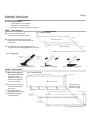
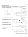
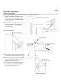
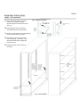
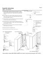
Snap-It Storage Cabinets
Assembly Instructions
Model
Mo
oKDE7824,KDE7848
ddeel Numbers:
Nuum
N
mbbeerrs: KDE7236,
KDE
DE7
KDE7824, KDE7848
Model Numbers: KDE7236,M
Safety Instructions
1
CAUTION: Use caution when handling and assembling metal parts. Metal may have sharp edges or corners.
The use of protective gloves is recommended when assembling product.
• This unit should be installed on a level, dry surface.
• Do not use this unit as a step ladder. Do not climb on the unit.
• This unit is not intended to be used in any other manner than for storage.
• Always distribute weight evenly on shelves. Store heavier items on the bottom shelves.
• Do not use in high-humidity, high-corrosion locations. Humidity should be under 60%.
All assembly instructions must be followed exactly or the unit may not be assembled correctly and may not be stable. Assemble the unit on level surface.
Parts List
B2 - Right Side Panel
A2 - Right Back Panel
1 each
Slots
1 each
Slots
Slots
F - Top
Tabs
Tabs
Tabs
1 each
G - Shelf
Electronic
Lock
4 each
D - Bottom
1 each
C - Inside Face Plate
1 each
E - Outside Face Plate
B1 - Left Side Panel
A1 - Left Back Panel
1 each
1 each
H1 - Left Door
1 each
Part
Left Side Panel - B1
Right Side Panel - B2
Left Back Panel - A1
Right Back Panel - A2
Left Door - H1
Right Door - H2
Top - F
Shelf - G
Bottom - D
Inside Face Plate - C
Outside Face Plate - E
Bolt / Wingnut - I
Shelf Clip - S
Door Rod Guide - L
Hinge Pin Guide - K
Top Stop - J
Door Bumper - Q
Hinge Pin - O
External Power Supply
Keys
1 each
Qty
1
1
1
1
1
1
1
4
1
1
1
4
16
2
4
2
4
4
1
2
NOTE: Some of the components are factory installed.
H2 - Right Door
1 each
External Power Supply 1 each
I - Screw / Wing Nut
4 each
Keys 2 each
J - Top Stop
L - Door Rod Guide
2 each
(2 preinstalled)
2 each
(1 preinstalled)
K - Hinge Pin Guide
Q - Door Bumper
4 each
(2 preinstalled)
4 each
(4 preinstalled)
S - Shelf Clip
O - Hinge Pin
4 each
16 each
Atlantic Metal Industries, Inc.
6302 Anderson Road, Tampa, Florida 33634
(813) 884-7541 Phone; (813) 884-2058 Fax
Copyright
Atlantic Metal 2008
12-008/1
Snap-It Storage Cabinets
Assembly Instructions
Page 2
General Instructions
TIPS FOR EASIER ASSEMBLY:
• 2-person assembly is recommended.
• Assemble the unit on a flat surface.
• Check the parts carefully and follow the instructions.
Step 1 - Back Assembly
Fig. 1 - Align back panels
A) Lay the two back panels on a flat
Tabs
surface. Position as illustrated. See Fig. 1.
Bend is up
B) Place the Right Back Panel (A2) next to the
A2 - Right Back Panel
Left Back Panel (A1) and insert the tabs into the
matching slots.
Tabs
Slots
C) Once all the tabs are started, slide the Back Panels
Bend is up
A1 - Left Back Panel
in opposite directions to fully engage the tabs. See Fig. 2.
Tabs
Fig. 2 - Engage tabs
Right Back Panel
Left Back Panel
A2
A1
Align the tabs with the matching slots
Insert the tabs into the matching slots
Slide the panels to fully engage the tabs
Step 2 - Side Assembly
A) While the Back Panels are
Fig. 3 - Install side panels
J - Top Stop (installed at factory DO NOT remove)
still lying on a flat surface,
align the slots on the
Right Side Panel (B2) with
the tabs on the Right Back
Panel (A2). See Fig 3.
B) Insert the tabs into the slots.
Make sure that all the tabs
are inserted.
C) Slide the Side Panel to
fully engage them in the slots
D) Repeat the steps with the
Left Side Panel (B1).
Holes for Face Plate
B2 - Right Side Panel
Insert the tabs into the
matching slots and slide
the panel to fully engage
Slots
Tabs
J - Top Stop (installed at factory DO NOT remove)
Holes for Face Plate
A2 - Right Back
Panel
A1 - Left Back
Panel
B1 - Left Side Panel (shown transparent)
Snap-It Storage Cabinets
Assembly Instructions
Page 3
Step 3 - Face Plate and Bottom Assembly
A) Attach the Inside Face Plate (C) using the Screws
I - Screws / Wing Nuts
Fig. 1 - Install inside face plate
and Wing Nuts (I). Make sure the door rod and hinge
holes are facing the top of the cabinet. Use the
inside pair of holes and do not fully tighten the
Wing Nuts at this time.
Door hinge hole
C - Inside Face Plate
Door rod
hole
Screws
Insert into the
inside pair of
holes
Wing nuts
Use the inside
pair of holes, closest
to the center of the cabinet, on
each side.
Fig. 2 - Install bottom
Angle the Bottom slightly
to engage the 3 supports
on the Inside Face Plate
first.
B) Insert the Bottom (D) into the assembly. The notch in
its center should be in rear, facing the back. See
Fig. 2.
Slide the Bottom (D) down and angle it slighty to
partially engage all 3 of the supports on the Inside
Face Plate (C). Push the rear of the Bottom (D)
down, making sure that the supports on the back
and side panels are all partially engaged.
D - Bottom
Tap the Bottom (D) down around the edges until it is
fully seated on each of the supports.
Supports
The notch
in the center
of the Bottom is
toward the back.
C) Fully tighten the Wing Nuts holding the Inside Face
Plate (C).
Fig. 3 - Install outside face plate
Snap the Outside
Face Plate over the
Inside plate.
Door hinge hole
E - Outside Face Plate
D) Install the Outside Face Plate (E) by snapping it in
place over the Inside Face Plate (C). Make sure the
door rod and hinge holes are facing the top of the
cabinet. See Fig. 3.
Door rod
hole
Door hinge hole
Snap-It Storage Cabinets
Assembly Instructions
Page 4
Step 4 - Top Installation
A) Carefully stand the cabinet assembly to an upright
Fig. 1 - Top stops
position. Note the plastic Top Stops (J) that are
located on the front of each side panel. Do NOT
remove these as they are required to hold the top
in place. See Fig. 1.
J - Top Stop (installed at factory DO NOT remove)
B) Insert the front edge of the Top (F) over the side
panels and Top Stops (J). Make sure that the
side panels are inserted in the flanges located
under the the Top (F).
Carefully stand the cabinet upright
J - Top Stop (installed at factory DO NOT remove)
Fig. 2 - Place top in place
The Top Stop (J) keeps the front of the Top (F)
from lifting up.
Place the front edge of the Top
over the side panels and Top Stops (F).
Apply slight downward pressure
to partially engage all flanges.
F - Top
Make sure the
side panels are
inserted in the
flange on the
Top (F).
Guide the back
panels into the
flanges - make
sure both are
partially engaged.
Apply forward pressure
to Top (F).
Fig. 3 - Insert back and sides into flanges
C) Press the Top (F) forward and guide the back panels
into the flanges located under the Top (F). See Fig. 3.
D) Make sure the both of the side panels and each of the
back panels are partially engaged in the flanges
before pushing the Top (F) down fully.
Press Top (F) down until
it snaps into place and all of
the flanges are fully engaged.
E) Once the flanges are partially engaged, push the
Top (F) down until it snaps into place and all the
flanges are fully engaged. See Fig. 4.
Press
down
until tabs
lock into
place.
Fig. 4 - Push top down
Snap-It Storage Cabinets
Assembly Instructions
Page 5
Step 5 - Shelf Installation
A) At the desired shelf height, insert 4 Shelf
Fig. 1 - Shelf clip installation
Clips (S) into the slots located inside
the front edges of the Side and Back Panels.
See Fig. 1.
B) Angle a Shelf (G) into the cabinet above
the installed Clips with its rear tilted down.
S - Shelf Clip
Slots in
front and
back of
cabinet
Shelves rest on top
of clips
Insert clips
into slots
C) Set the rear of the Shelf (I) onto the Shelf Clips (S)
placed in the Back Panels. See Fig. 2.
D) Tilt the Shelf (I) down until it rests on the
front Shelf Clips (S). If the Shelf is uneven,
reposition the Shelf Clips into appropriate
locations to level it.
E) Repeat this process for the remainder of
the shelves.
G - Shelf
Angle the
back of
the shelf
downward
and rest it
on the rear
shelf clips
Tilt the front
of the shelf
downward
to rest it on
the front
shelf clips
G - Shelf
G - Shelf
G - Shelf
G - Shelf
Insert 4 Shelf
Clips (S) at
equal heights
Fig. 2 - Shelf installation
Repeat the
process for the
other
shelves
Snap-It Storage Cabinets
Assembly Instructions
Page 6
Step 6 - Door Installation
Fig. 1 - Install plastic guides
A) Install the Hinge Pin Guides (K) and the Door Rod Guide (L) into the
K - Hinge Pin Guide
bottom face plate. Make sure that they are fully seated. The Hinge Pin
Guides are preinstalled in the top. Verify that they are also fully seated.
See Fig. 1.
L - Door Rod Guide
B) Use a Hinge Pin (O) to make sure that the hinge holes on the top and
The Hinge Pin and Rod Guides
are factory installed on the top
bottom of each door are clear of excess paint and that the pin will slide
freely during installation. See Fig. 2.
C) Install a Hinge Pin (O) into the top hinge hole of each door. Bend the tabs
on the door to secure them in place. See Fig. 3.
K - Hinge Pin Guide
Fig. 2 - Remove excess paint
D) Put the Left Door (H1) in place, inserting the installed top Hinge Pin (O)
Use a Hinge Pin to
clear any excess paint from
ALL the holes in the doors so
that they slide freely before
installing
into the top Hinge Pin Guide (K). NOTE: The door fits very closely between
the top and bottom. See Fig. 4.
E) Align the bottom hinge pin holes in the door and cabinet and install the
O - Hinge Pin
bottom Hinge Pin (O). See Fig. 5.
Hinge pin holes in the doors
sometimes have excess paint,
making the pin fit tight.
F) Repeat this process for the Right Door (H2).
NOTE: The Door Bumpers (Q) are factory installed on each of the doors.
Fig. 3 - Install the top hinge pins
Fig. 4 - Put door in place
Insert the installed
top Hinge Pin into the
cabinet top.
Install the top Hinge
Pins in both doors.
Q - Door Bumper
(factory installed)
H2 - Right Door
with electronic lock
Locking Tab
Insert the Hinge Pin
until it is past the
locking tab
Align the bottom
holes, insert the
pin and bend the
tab to secure it in
place
Turn the Hinge Pin
Slide the door
into place
Bend the locking tab
over the Hinge Pin,
securing it in place.
H1 - Left Door
Q - Door Bumper
(factory installed)
with no lock (installed)
Fig. 5 - Insert bottom hinge pin
After assembly is complete, MILD SOAP and WATER can be used to clean the unit by wiping with a SOFT CLOTH.
Laptop Computer Safe/Security Cabinet - Instruction Manual
Electronic Coded Lock Instructions
Page 47
Selecting the Mode of Operation
The Electronic Lock can be programmed to operate in either of two modes of operation:
1) Standard Operation Mode - In this mode, both the Personal and Administrator passwords are stored in the system memory until they
are manually changed.
2) Auto Reset Mode - In this mode, the Personal password is automatically reset to the default after opening the electronic lock. The
Administrator password does not automatically reset to the default. This mode is ideal for most hotel applications.
Selecting the Mode of Operation:
1) Press # key and enter 4 0 9 3 4 0 9 3.
2) Use the 0 key to switch modes (ON, OFF).
Default Passwords
The system has two passwords: personal and administrator, either can be used to open the door. The factory presets for each are as follows:
- Personal / guest: 1 2 3 4
- Administrator: 1 2 3 4 5 6
THESE ARE COMMONLY USED PERSONAL AND ADMINISTRATOR DEFAULT PASSWORDS. FOR MAXIMUM SECURITY, BOTH PASSWORDS
SHOULD BE IMMEDIATELY CHANGED. FAILURE TO IMMEDIATELY CHANGE BOTH PASSWORDS WILL COMPROMISE THE SECURITY OF THIS
CABINET AND MAY RESULT IN THE THEFT OF ITS CONTENTS.
Lock Procedures
Opening the Door
1) Press # key. The display will read “--------”. Enter the password and press # key to confirm. Should you wish to conceal the password
as it is entered, press the * key once before entering the code. Press the * key twice to disable concealment. Once the password is
accepted, the display will read “OPEN”. The lock will stay open for approximately 7 seconds.
NOTE: An alarm will sound if an incorrect password is tried three times. It will sound for 1 minute or until a correct password is entered.
Changing the Personal Password
Standard Operation Mode
1) Open the door with the personal password (default = 1 2 3 4).
2) While the display reads “OPEN” press the * key. The display will read “--------”.
3) Enter the new password and press the # key to confirm. The display will read “IN”. If the password has 8 digits, the confirmation will
be done automatically.
Auto Reset Mode
1) Open the door with the guest password (default = 1 2 3 4).
2) Before closing the cabinet, press the reset button inside the door. The display will read “--------”.
3) Enter the new password and press the # key to confirm. The display will read “IN”. If the password has 8 digits, the confirmation will
be done automatically.
If the lock program is in Auto Reset Mode, the personal / guest password will automatically be reset to the default code after opening the lock.
FOR MAXIMUM SECURITY WHILE IN AUTO RESET MODE, THE PERSONAL PASSWORD SHOULD BE CHANGED EACH TIME THE
CABINET IS CLOSED WHEN VALUABLES ARE STORED.
Changing the Administrator Password
1) Open the door with the administrator password (default = 1 2 3 4 5 6).
2) While the display reads “OPEN” press the * key. The display will read “--------”.
3) Enter the new password and press the # key to confirm. The display will read “IN”. If the password has 8 digits, the confirmation will
be done automatically.
Setting the Date and Time
1)
2)
3)
4)
Press the * key. Enter 8 0 0 8 8 0 0 8 to access the Date and Time function.
Enter the year by using the 8 and 0 keys to scroll the numbers up and down. When correct, press the # key.
Repeat the previous step for the month, day, hour (military time), minute and day of the week successively.
When finished, wait several seconds; the flashing of the display will stop and the information will be stored.
Laptop Computer Safe/Security Cabinet - Instruction Manual
Electronic Coded Lock Instructions
8
8
Page 5
Retrieve the Open Door Records
1) Enter the password, press # and the display will read “OPEN” with a blue light. After a few seconds, the "OPEN" will disappear but the blue
light will still be on. At this moment, press the 0 key to access the records.
2) The display will cycle through the date, time and the type of password (PASS 1 or PASS 2) on the most recent opening. Pressing 0 while
the record is visible will display next most recent opening. Keep pressing 0 to scroll backwards through all the records.
Battery Failure
1) Connect the external power supply to the socket on the bottom of the keypad and follow the normal entry procedures, or use the Key Entry
Procedure described below to access the cabinet. Replace the batteries.
Key Entry
1) The keypad can be bypassed by using the key should
the electronic lock become inoperable.
2) Remove the cover by prying it up from the bottom.
3) Insert the key into the lock and turn it counter clockwise.
4) While the key is turned, turn the handle clockwise
to release the lock.
Lift here to remove the cover
Remove Cover
Insert Key
While turning Key.
tun Handle clockwise
Turn Key counter clockwise
Notes:
1) After a power down, the open door records will not be lost. However, the date and time will not be kept.
2) When using the keypad, if a key is not pressed for 10 seconds, the system will return to standby status.
Forgotten Passwords
1) The passwords can be reset by obtaining specific instructions from the manufacturer. For security reasons, to obtain keys or a product
reset, the manufacturer will require the following:
A) Proof of purchase
B) A notarized letter requesting a reset that indicates that the person requesting the reset or keys is the certified owner of the
product.
Please call 800-264-3453 for additional information.