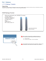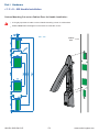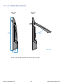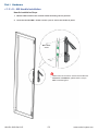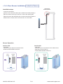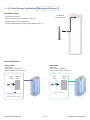
1
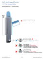
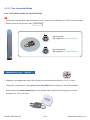
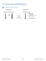
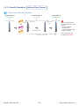
SmartCard Access Control for Cabinets
User Manual
Utilities ISU-01
S-600
Standalone Cabinet SmartCard Handle
Designed and manufactured by Austin Hughes
UM-ISU-S600-Q413V5
www.austin-hughes.com
Legal Information
First English printing, October 2002
Information in this document has been carefully checked for accuracy; however, no guarantee is given to the correctness
of the contents. The information in this document is subject to change without notice. We are not liable for any injury or
loss that results from the use of this equipment.
Safety Instructions
Please read all of these instructions carefully before you use the device. Save this manual for
future reference.
■
■
■
■
■
■
■
■
■
■
■
Unplug equipment before cleaning. Don’t use liquid or spray detergent; use a moist cloth.
Keep equipment away from excessive humidity and heat. Preferably, keep it in an air-conditioned environment with
temperatures not exceeding 40º Celsius (104º Fahrenheit).
When installing, place the equipment on a sturdy, level surface to prevent it from accidentally falling and causing
damage to other equipment or injury to persons nearby.
When the equipment is in an open position, do not cover, block or in any way obstruct the gap between it and the
power supply. Proper air convection is necessary to keep it from overheating.
Arrange the equipment’s power cord in such a way that others won’t trip or fall over it.
If you are using a power cord that didn’t ship with the equipment, ensure that it is rated for the voltage and current
labeled on the equipment’s electrical ratings label. The voltage rating on the cord should be higher than the one listed
on the equipment’s ratings label.
Observe all precautions and warnings attached to the equipment.
If you don’t intend on using the equipment for a long time, disconnect it from the power outlet to prevent being
damaged by transient over-voltage.
Keep all liquids away from the equipment to minimize the risk of accidental spillage. Liquid spilled on to the power
supply or on other hardware may cause damage, fire or electrical shock.
Only qualified service personnel should open the chassis. Opening it yourself could damage the equipment and
invalidate its warranty.
If any part of the equipment becomes damaged or stops functioning, have it checked by qualified service personnel.
What the warranty does not cover
■
■
■
Any product, on which the serial number has been defaced, modified or removed.
Damage, deterioration or malfunction resulting from:
Accident, misuse, neglect, fire, water, lightning, or other acts of nature, unauthorized product modification, or
failure to follow instructions supplied with the product.
Repair or attempted repair by anyone not authorized by us.
Any damage of the product due to shipment.
Removal or installation of the product.
Causes external to the product, such as electric power fluctuation or failure.
Use of supplies or parts not meeting our specifications.
Normal wear and tear.
Any other causes which does not relate to a product defect.
Removal, installation, and set-up service charges.
□
□
□
□
□
□
□
□
Regulatory Notices Federal Communications Commission (FCC)
This equipment has been tested and found to comply with the limits for a Class B digital device, pursuant to Part 15 of
the FCC rules. These limits are designed to provide reasonable protection against harmful interference in a residential
installation.
Any changes or modifications made to this equipment may void the user’s authority to operate this equipment. This
equipment generates, uses, and can radiate radio frequency energy and, if not installed and used in accordance with the
instructions, may cause harmful interference to radio communications.
However, there is no guarantee that interference will not occur in a particular installation. If this equipment does cause
harmful interference to radio or television reception, which can be determined by turning the equipment off and on, the
user is encouraged to try to correct the interference by one or more of the following measures:
■ Re-position or relocate the receiving antenna.
■ Increase the separation between the equipment and receiver.
■ Connect the equipment into an outlet on a circuit different from that to which the receiver is connected.
UM-ISU-S600-Q413V5
www.austin-hughes.com
Content
Part I. Hardware
< 1.1 > Package Contents
P.1
< 1.2 > Overall Installation Diagram
P.2
< 1.3 > S - 600 Handle Installation
P.3
< 1.4 > Door Sensor Installation ( Inductive Sensor / Mechanical Sensor )
P.9
Part II. Handle Usage & Operation
< 2.1 > Two Important Notes
P.13
< 2.2 > Handle Operation with Door Sensor
P.15
< 2.3 > Handle Operation without Door Sensor
P.17
Part III. Hardware Specifications
P.19
Part IV. Software Download
< 4.1 > Software Features & Hardware Requirements
P.20
< 4.2 > Supported OS Platform & Language
P.21
< 4.2 > Utilities ISU-01 Download & Installation
P.22
< 4.3 > Driver Installation for Data Input Cable
P.23
Part V. Software Usage
< 5.1 > Initial Handle Configuration
P.27
< 5.2 > Card Assignment
P.30
< 5.3 > Export & Import Handle Configuration
P.31
Part VI. FAQ
P.33
Part VII. Troubleshooting
P.34
Part VIII. Optional Acccessories
P.35
UM-ISU-S600-Q413V5
www.austin-hughes.com
Part I. Hardware
< 1.1 > Package Contents
Unpacking
The equipment comes with the standard parts shown on the package contents. Check and make sure they are included and in good
condition. If anything is missing, or damage, contact the supplier immediately.
S-600 Package Content
- 600 smart card handle, pair ( MiFARE / Proximity )
- Y-Power cable x 1
- Activated smartcard x 1
- 2.5A power adapter x 1
- 6’ Power cord x 1
- Key x 1
- Cable clip x 8
- M5 x 12mm screw x 6
Patented and Worldwide
Patents Pending
Each package bundled with activated smartcard x 1.
The card on the bottom right shows two information :
< 1 > Card number
< 2 > Handle ID number x 2 for two handles
Card# 12345678
Card# 12
ID# 1234
ID# 123456789-S8P001
This bundled smartcard has been activated in advance and
authorized to unlock these two handles in the package.
UM-ISU-S600-Q413V5
P.1
www.austin-hughes.com
< 1.2 > Overall Installation Diagram
2
5
2
6
5
3
3
1
2
1
2
4
7
4
Rear Door
Front Door
1
S-600P Proximity / S-600M MiFARE SmartCard handle
2
Optional door sensor with cable : 2pcs for front & rear door ( 2m )
3
Power cable ( door section ) : 2pcs for front & rear door ( 2m )
4
Data input connector ( for handle activation / data input / configuration )
5
Joint connector of
6
Y-Power cable ( cabinet section )
7
Universal Auto switching 2.5A power adapter & 6’ power cord
UM-ISU-S600-Q413V5
3
&
6
P.2
www.austin-hughes.com
Part I. Hardware
< 1.3 > S - 600 Handle Installation
Custom Mounting Cut-out on Cabinet Door for Handle Installation :
It is highly important to make a correct handle mounting cut-out on cabinet door.
Please 100% follow the diagram on the below to make the cut-out.
Unit : mm
Cabinet
>>>>>
door
UM-ISU-S600-Q413V5
P.3
www.austin-hughes.com
< 1.3 > S - 600 Handle Installation
Side View
Close
Side View
Open
54°
273
Unit : mm
36
S-600 handle design supports left side & right side open
UM-ISU-S600-Q413V5
P.4
www.austin-hughes.com
Part I. Hardware
< 1.3 > S - 600 Handle Installation
Handle Installation Steps
1. Mount S-600 handle to the custom handle mounting cut-out position.
2. Insert the bundled M5 x 12mm screw x 3 pcs to secure the handle in place.
M5 x 12mm
screw
While insert the screws to secure the handle with
electronic screwdriver, please set the torque
NOT exceed 8 kgf/cm
UM-ISU-S600-Q413V5
P.5
www.austin-hughes.com
< 1.3 > S - 600 Handle Installation
Parts of Cabinet Door Locking Bar
Three parts available for cabinet manufacturer
3
to produce the cabinet door locking bar system
integrated with S-600 handle .
2
1 Locking bar handle bracket, pc
Order part no. : 404 - 8 - 02111
material : alloy
( fixing screw not provided )
>>>>>
Dimension Diagram
on next page
2
Locking
Bar
1
3
2 Locking bar retaining bracket, pc
Order part no. : 314 - 0 - 10010
material : alloy
( fixing screw not provided )
2
Dimension Diagram
on next page
3 Locking bar roller, pc
Order part no. : 314 - 0 - 10020
material : alloy
( fixing screw not provided )
Dimension Diagram
on next page
3
UM-ISU-S600-Q413V5
P.6
2
www.austin-hughes.com
Part I. Hardware
< 1.3 > S - 600 Handle Installation
1 Locking bar handle bracket, pc
Order part no. : 404 - 8 - 02111
material : alloy
( fixing screw not provided )
UM-ISU-S600-Q413V5
P.7
www.austin-hughes.com
< 1.3 > S - 600 Handle Installation
2 Locking bar retaining bracket, pc
Order part no. : 314 - 0 - 10010
material : alloy
( fixing screw not provided )
3 Locking bar roller, pc
Order part no. : 314 - 0 - 10020
material : alloy
( fixing screw not provided )
UM-ISU-S600-Q413V5
P.8
www.austin-hughes.com
Part I. Hardware
< 1.4 > Door Sensor Installation Inductive Sensor
Optional door sensor is an essential accessories as users can be alerted by visual and audio alarm for
unauthorized access.
Inductive Door Sensor, pair ( S-DSI )
Features
light weight / adhesive
mini size ( 32.5 x 12.2 x 9.2 mm )
no custom cutting required on door
Front View
12.2 mm
2
1
32.5 mm
3
4
9.2 mm
Side View
1
Sensor area
2
Red LED ( light up while door opening )
3
2m cable
4
Cable jack ( connect to handle )
5
2mm adhesive tape
5
Package content
Inductive sensor w/ 2m cable x 2
2mm adhesive tape x 6
Requirements
cabinet frame made of ferrous metal ( iron )
sensing distance 3mm
UM-ISU-S600-Q413V5
P.9
www.austin-hughes.com
< 1.4 > Door Sensor Installation Inductive Sensor
Suggested
sensor position
Installation steps
- connect to the handle
- guide & fix the cable with cable clips ( bundle with handle package )
- place the sensor at the top of the door, close to the opening side
- adjust the sensor with adhesive tape to ensure the sensing distance
between door to frame within 3mm while door in close status
Sensor Operation
DOOR OPEN
- open door
- inductive sensor lose detection with cabinet frame
- Red LED of sensor light up
- DOOR OPEN SIGNAL sends out
DOOR CLOSE
- close door
- inductive sensor detects the cabinet frame
- DOOR CLOSE SIGNAL sends out
Door
frame
Cabinet
frame
Door
frame
CLOSED
Cabinet
frame
OPENED
Sensing distance
< 3mm
UM-ISU-S600-Q413V5
Sensing distance
> 3mm
P.10
www.austin-hughes.com
Part I. Hardware
< 1.4 > Door Sensor Installation Mechanical Sensor
Mechanical Door Sensor ( S-DSW )
Features
low cost / precise
cost efficient integration to new cabinet
Front View
unit : mm
Top View
1
Side View
11
7.3
22.5
3
15.0
2
3
1
Steel mounting plate with 2 screw holes
2
Cable connector
3
Press button ( total travel distance : 9.25 mm
15.75
6.5
52.0
9.25
)
( min. actuation distance : 3.00 mm )
Package content
Mechanical sensor w/ 2m cable x 2
Mounting screws 6#32x4.5mm x 2
unit : mm
Requirements
37.5
custom hole cutting required on doors
23
ordering a sample for custom cutting is highly suggested
2-
12.5
6.3
min. actuation distance : 3.00 mm
total travel distance : 9.25 mm
3 .5
Dimension of door cutting hole
- circle hole x 2 for screw mounting
- rectangle hole x 1 for sensor installation
UM-ISU-S600-Q413V5
P.11
www.austin-hughes.com
< 1.4 > Door Sensor Installation Mechanical Sensor
Installation steps
Suggested
sensor position
- connect to the handle
- place the sensor at the top middle of the door
- install the sensor in the custom hole
- secure it with bundled mounting screws 6#32x4.5mm x 2
Sensor Operation
DOOR CLOSE
- close door
- Sensor button is pressed on
DOOR OPEN
- open door
- Sensor button is released
- DOOR CLOSE SIGNAL sends out
- DOOR OPEN SIGNAL sends out
Door
frame
Door
frame
Cabinet
frame
Cabinet
frame
OPENED
CLOSED
Button released
Actuation distance > 3mm
Physical touch required
UM-ISU-S600-Q413V5
P.12
www.austin-hughes.com
Part II. Handle Usage & Operation
< 2.1 > Two Important Notes
Handle Sensor Area & SmartCard Mode
Sensor
area
Present the smartcard and touch the
handle sensor area for 1 to 2 seconds
Smartcard mode
For smartcard operation, keep key cylinder
always to 12 o’clock direction.
Key lock mode
Key cylinder to 9 o’clock direction
Under key lock mode, even present the
smartcard, the handle still keeps locked.
Key unlock mode
Key cylinder to 3 o’clock direction
Under key unlock mode, the handle keeps unlocked.
UM-ISU-S600-Q413V5
P.13
www.austin-hughes.com
< 2.1 > Two Important Notes
Lock / Unlock the handle by mechanical key
Unless the smartcard handle is defective, lock / unlock the handle by key is NOT recommended
Please insert & turn the key with push force
Key lock mode
Key cylinder to 9 o’clock direction.
Key unlock mode
Key cylinder to 3 o’clock direction.
Maintenance Key
( MK-001 )
Improper key usage may cause the cylinder stuck at abnormal direction 1 to 2 o’ clock.
Under this circumstance, the maintenance key (MK-001) is required to solve the problem.
Please insert the maintenance key to the cylinder with push force for turning it to normal
direction 9 or 12 or 3 o’clock.
UM-ISU-S600-Q413V5
P.14
www.austin-hughes.com
Part II. Handle Usage & Operation
< 2.2 > Handle Operation
with Door Sensor
How to unlock the handle & open the door properly
Locked status in
blue or green
Unlocked status in
silver white
>>>
Flashing
Flashing
Stop
OR
+
To open the door
( within 10 seconds )
Within 10 seconds after
smartcard detection, users
should :
- lift up the handle
- open the door
- return the handle to park
position properly in case
reckless collision causes
handle damage.
Over 10 seconds, the
handle still keeps unlock.
Unlock the handle but NOT open the door
Locked status in
blue or green
Unlocked status in
silver white
Unlocked status in
red
Flashing
OR
>>>
+
( over 10 seconds )
If DO NOT lift up the handle
and open the door within 10
seconds, the LED will change
to RED to draw user’s attention
that the handle in unlock status
and cabinet security at risk now.
Unauthorized door-open
Locked status in
blue or green
Unlocked status in
red
Flashing
NO Authenticated
Smartcard Detection
UM-ISU-S600-Q413V5
Door Opening
improperly or by force
P.15
If the door is opened improperly or by force, handle LED
will turn to red flashing with
audio alarm ‘beep’ sound.
www.austin-hughes.com
< 2.2 > Handle Operation
with Door Sensor
How to close the door properly
Unlocked status in
silver white
Locked status in
blue or green
Users should :
- lift up the handle
- close the door
- return the handle to park
position properly
To close the door
( within 10 seconds )
UM-ISU-S600-Q413V5
Over 10 seconds, the
handle will auto-lock.
P.16
www.austin-hughes.com
Part II. Handle Usage & Operation
< 2.3 > Handle Operation
without Door Sensor
How to unlock the handle & open the door properly
Locked status in
blue or green
Unlocked status in
silver white
>>>
Flashing
Flashing
Stop
OR
+
Locked status in
blue or green
To open the door
( within 10 seconds )
Within 10 seconds after
smartcard detection, users
should :
- lift up the handle
- open the door
- return the handle to park
position properly in case
reckless collision causes
handle damage.
Over 10 seconds, the
handle will auto-lock.
Unlock the handle but NOT open the door
Locked status in
blue or green
Unlocked status in
silver white
Locked status in
blue or green
Flashing
OR
If DO NOT lift up the handle
and open the door within 10
seconds, the LED will change
to BLUE or GREEN and the
handle returns locked.
>>>
+
( over 10 seconds )
Unauthorized door-open
Locked status in
blue or green
NO Authenticated
Smartcard Detection
UM-ISU-S600-Q413V5
Unlocked status
in blue or green
Door Opening
improperly or by force
P.17
If the door is opened
improperly or by force,
handle LED remains in
BLUE or GREEN but no
any audio alarm “ beep ”
sounds for warning.
www.austin-hughes.com
< 2.3 > Handle Operation
without Door Sensor
How to close the door properly
Locked status in
blue or green
Unlocked status in
silver white
>>>
Flashing
Flashing
Stop
OR
+
Locked status in
blue or green
To close the door
( within 10 seconds )
UM-ISU-S600-Q413V5
P.18
Within 10 seconds after
smartcard detection, users
should :
- lift up the handle
- close the door
- return the handle to park
position properly
Over 10 seconds, the
handle will auto-lock.
www.austin-hughes.com
Part III. Hardware Specifications
Item
Power
100~240VAC, 50 / 60Hz 0.5A via AC / DC cord
Regulation Approval
FCC, CE
Operation
0˚ to 50˚C Degree
Storage
Environmental
-5˚ to 60 ˚C Degree
Relative Humidity
90%, non-condensing
Shock
50G peak acceleration (11 ms, half-sine wave)
Vibration
58~100Hz / 0.98G (11ms / cycle)
Gross Weight
1.82 kg / 4.0 lbs
Packing
310 x 310 x 95 mm
12.2 x 12.2 x 3.7 inch
Carton size ( W x L x H )
Safety Regulatory
Environmental
UM-ISU-S600-Q413V5
FCC & CE certified
RoHS2 & REACH compliant
P.19
www.austin-hughes.com
Part IV. Software Download
< 4.1 > Software Features & Hardware Requirements
Software Features
Utilities
ISU-01
Max. 500 pairs of handle
Max. 50 user card authentication per handle
Dual or single card mode authentication**
Enable or disable door sensor detection**
Detailed user card information
Reporting on configuration details
Log in password
** Optional feature
Hardware Requirements
Please prepare a notebook computer with the hardware specifications as below for InfraSolution S Utilities ISU-01.
Recommended hardware :
- Processor:
Dual Core 2GHz or above
- Memory:
2GB RAM
- Available Disk Space: 2GB
- Display:
1024 x 768 or higher resolution
USB port x 1 required for the data input cable & smartcard handle configuration
UM-ISU-S600-Q413V5
P.20
www.austin-hughes.com
Part IV. Software Download
< 4.2 > Supported OS Platform & Language
Supported OS platform & language list :
- MS Windows XP Professional with SP3 (32bit, English edition only)
- MS Windows 7 Professional with SP1 (32bit & 64bit, English edition only)
- MS Windows 8 Professional (32bit & 64bit, English edition only)
User can select the following languages under Control Panel > Region and Language in English Edition OS:
1)
Arabic (Saudi Arabia)
2)
Chinese (Traditional, Hong Kong S.A.R.)
3)
Dutch (Netherlands)
4)
English (Australia)
5)
English (United Kingdom)
6)
English (United States)
7)
French (France)
8)
German (Germany)
9)
German (Switzerland)
10) Italian (Italy)
11) Japanese (Japan)
12) Korean (Korea)
13) Norwegian (Norway)
14) Portuguese (Portugal)
15) Russian (Russia)
16) Spanish (Spain)
17) Turkish (Turkey)
UM-ISU-S600-Q413V5
P.21
www.austin-hughes.com
< 4.3 > Utilities ISU-01 Download & Installation
After the handle installation, please take the following steps to install the utilities :
1. Prepare a notebook computer to download the handle setup utilities from the link :
http://www.austin-hughes.com/support/utilities/infrasolutionS/ISU-01.msi
2. Double click the
ISU-01.msi
ISU-01.msi
and follow the instruction to complete the installation.
click “ Next ”
click “ Install ”
click “ Finish ”
Complete
UM-ISU-S600-Q413V5
P.22
www.austin-hughes.com
Part IV. Software Download
< 4.4 > Driver Installation for Data Input Cable
Before initial configuration for handles, user MUST install the driver for the data input cable ONCE.
Please follow 13 steps below to complete the installation.
Step 1.
Connect the handle to the notebook computer via the handle data input cable ( ISW-USB-1.8 ).
Make sure the handle in power ON status
Handle Data Input Cable
ISW-USB-1.8
To
USB port
To
handle data
connector
If the notebook is MAC model, users may need to download the USB driver to run Windows OS under
MAC notebook PC.
http://www.austin-hughes.com/support/utilities/infrasolutionS/ISW-USBV20828-32bit.7z
OR
http://www.austin-hughes.com/support/utilities/infrasolutionS/ISW-USBV20828-64bit.7z
Step 2.
Right click “ My computer “ & Select “ Manage “. Click “ Device Manager “.
Then user can see an improper USB UART driver installed under “ Other devices ” .
UM-ISU-S600-Q413V5
P.23
www.austin-hughes.com
< 4.4 > Driver Installation for Data Input Cable
Step 3.
Right Click the improper installed USB UART driver & Select “ Update Driver Software… “.
Step 4.
A window pops up & please Select “ Browse my computer for driver software “.
Step 5.
Click “ Browse “ to search the path of the driver software.
UM-ISU-S600-Q413V5
P.24
www.austin-hughes.com
Part IV. Software Download
< 4.4 > Driver Installation for Data Input Cable
Step 6.
Select C:\
>
Program Files
>
InfraSolution S – Setup Utilities
>
Driver & Click “ OK “
Step 7.
Click “ Next “ to install the driver.
Step 8.
It takes a few seconds to complete. When complete, Click “ Close “
Step 9.
“ USB Serial Converter “ shows under “ Universal Serial Bus controllers ”.
UM-ISU-S600-Q413V5
P.25
www.austin-hughes.com
< 4.4 > Driver Installation for Data Input Cable
Step 10.
Right Click “ USB Serial Port “ under “ Other devices “ & Select “ Update Driver Software… ”.
Step 11.
Select “ Browse my computer for driver software “.
Step 12.
Click “ Browse “ to search the correct path of the driver software & Click “ Next “ to install the driver.
Step 13.
It takes a few seconds to complete. When complete, Click “ Close ”
Complete
UM-ISU-S600-Q413V5
P.26
www.austin-hughes.com
Part V. Software Usage
< 5.1 > Initial Handle Configuration
After hardware & software installation, please take the following steps to configure the handle.
( 1 ) Prepare the notebook computer installed with utilities ISU-01
( 2 ) Connect to the handle via the handle data input cable ( ISW-USB-1.8 )
( 3 ) Make sure the handle in power ON status
( 4 ) Configure the handle according to the UI
( 5 ) After finish the handle configuration, please repeat the steps for other handles One by One
Handle Data Input Cable
ISW-USB-1.8
To
USB port
To
handle data
connector
If the OS platform of the notebook computer is MS Windows 7, please take the following steps :
- Right Click InfraSolution S Utilities ISU-01 , and then Select “ Properties “.
- Click the “ Compatibility “ tab.
- Tick the box “ Run this program as an administrator ”, and then Click “ OK ” .
If don’t take the above steps, the UI will not display properly.
UM-ISU-S600-Q413V5
P.27
www.austin-hughes.com
< 5.1 > Initial Handle Configuration
Handle Information
In < Handle Information >, shows the handle ID #, model, card type & the time of last configuration.
UM-ISU-S600-Q413V5
P.28
www.austin-hughes.com
Part V. Software Usage
< 5.1 > Initial Handle Configuration
Handle Location
In < Handle Location >, record the Zone, Rack and Handle position of the handle.
Door Sensor ( Option )
In < Door Sensor >, enable or disable the door sensor. Default is “ Disable “.
Ensure you have ordered door sensors
and finished the installation. Otherwise,
DO NOT enable door sensor as it will
cause malfunction.
Card Access Mode ( Option )
In < Card Access Mode >, select the handle to run as Normal OR Dual Card Authentication mode.
- If select Dual Card Authentication, please
input Administrator card no. .
- Only ONE admin. card for each handle.
- User MUST order Dual card authentication
option before delivery.
- While unlock the handle and open the door
under Dual card authentication mode, present
the admin. card first, then user card within 10
seconds.
UM-ISU-S600-Q413V5
P.29
www.austin-hughes.com
< 5.2 > Card Assignment
In < Card Assignment >, assign, edit or delete user card.
Card Assignment by two methods
( 1 ) Click Card Edit, then direct input the last 8 digits of the card number to the field
( 2 ) Click Card Edit, then present the smartcard to the handle and the last 8 digits of
the card number will be input to the field simultaneously & automatically
Card no. Change
( 1 ) Click Card Edit, then change the existing card numbers in the field
Card Delete
( 1 ) Click Card Edit, then delete the card number in the field one by one
All Card Delete
( 1 ) Click Delete, then confirm this command and all card assignment will be deleted
Click “ Apply “ to finish the above configuration for smartcard.
UM-ISU-S600-Q413V5
P.30
www.austin-hughes.com
Part V. Software Usage
< 5.3 > Export & Import Handle Configuration
In < Export > and < Import >, provide a quick way to configure other handles with same or similar configuration
on < Card Assignment >, < Door Sensor >, < Card Access Mode >.
Steps for
Export
:
( 1 ) Click “ Export “ and Click “ Yes “ from the pop up window
( 2 ) Provide the name and path of the export file and follow the instruction to complete the export
UM-ISU-S600-Q413V5
P.31
www.austin-hughes.com
< 5.3 > Export & Import Handle Configuration
Steps for
Import
:
( 1 ) Select the handle which you want to import handle configuration file
( 2 ) Connect the handle to the notebook computer via the handle data input cable ( ISW-USB-1.8 )
( 3 ) Click “ Import “ and Click “ Yes “ from the pop up window
( 4 ) Select the file to import & follow the instruction to complete the import step
( 5 ) After import completed, edit the field (s) on Zone , Rack …… if necessary
( 6 ) Click “ Apply “ to finish file import
UM-ISU-S600-Q413V5
P.32
www.austin-hughes.com
Part VI.
FAQ
Utilities – ISU-01
1. What is Utilities – ISU-01 ?
- ISU-01 is a Windows based utility to provide a simple & user friendly way for initial handle setup
2. Which OS platform does ISU-01 support ?
- MS Windows XP Professional with SP3 (32bit)
- MS Windows 7 Professional with SP1
3. Why the handle ID no. NOT show in UI ?
- ensure the handle is in power ON status
- ensure the driver installation for data input cable ( ISW-USB-1.8 ) completed
4. How to do if lost the user card ?
- open the door by key and edit the card assignment
5. Why can’t select “ Dual card authentication “ in ISU-01 ?
- ensure you have ordered this option before delivery
- if this option required after handle installation, you need to order a new handle with this option & replace the
existing one
Smartcard Handle
1. How many user card can I assign to each handle ?
- up to 50
2. How many Administrator card can I assign to each handle ?
- one
3. Why does the LED light change to RED after I present a valid user card without open the door ?
- remind you the cabinet security at risk now because the handle in unlock status but the door not open yet
4. Why can’t open the door even I presented a valid user card to the handle ?
- ensure the handle lock under the smartcard mode that key cylinder at 12 o’clock direction. Please refer user
manual “ Part II < 2.1 > Two Important Notes ” .
Others
1. Where can I get the USB driver for the data input cable ( ISW-USB-1.8 ) ?
- for 32 bit OS : http://www.austin-hughes.com/support/utilities/infrasolutionS/ISW-USBV20828-32bit.7z
- for 64 bit OS : http://www.austin-hughes.com/support/utilities/infrasolutionS/ISW-USBV20828-64bit.7z
2. Where can find the Catalog / User manual / Model list of Cabinet Smart Card Handle ?
- please visit www.austin-hughes.com
3. How can get further support ?
- please send email to [email protected] or [email protected]
UM-ISU-S600-Q413V5
P.33
www.austin-hughes.com
Part VII.
1.
Troubleshooting
Handle ID no. not shown in UI
Step 1 - Handle is OFF ?
ensure the handle is in power ON status
Step 2 - Check the driver of the data input cable installed properly ?
ensure the driver is installed properly. Please refer to user manual “ Part IV < 4.4 >
Driver installation for Data Input Cable “
Step 3 - Check the USB port of the notebook computer ?
Try to plug the data input cable into another USB port of the notebook computer.
Step 4 - Data input cable defective ?
Replace another data input cable.
2. Handle can’t be locked after closed the door
Step 1 - Check door sensor is installed ?
If NO door sensor is installed, please select disable in < Door sensor > in ISU-01.
Otherwise, the handle CANNOT be locked after you unlock it.
Step 2 - Door sensor sensing distance when door close greater than 3mm ( Inductive sensor only ) ?
Ensure the distance between the door sensor and cabinet frame is LESS than 3 mm. Please
refer to user manual “ Part I < 1.4 > Door Sensor Installation ”
Step 3 - Handle lock under key unlock mode and key cylinder at 3 o’clock direction ?
Ensure the handle lock under the smartcard mode that key cylinder at 12 o’clock. Please
refer to user manual “ Part II < 2.1 > Two Important Notes “
UM-ISU-S600-Q413V5
P.34
www.austin-hughes.com
Part VIII.
Optional Acccessories
Inductive door sensor, pair ( S-DSI )
•
•
•
Light weight, mini size & adhesive
No custom cutting required on doors
Easy for existing cabinet retrofit or integration to new cabinet
Mechanical door sensor, pair ( S-DSW )
•
•
•
•
Low cost
Precise
Cost efficient integration to new cabinet
Custom cutting required on doors
Handle data input cable, pc ( ISW-USB-1.8 )
•
Connect the smartcard handle to the laptop for
handle activation, data input & configuration
Individual key lock, set of two for front & rear door ( ISK-C051 )
•
Up to 500 individual key-locks available
Unique key lock ( ISK-UKL )
•
•
Unique key dedicated to single project / customer regionally
For project size over 500 cabinets
Dual card authentication ( DCS-01 )
• Software upgrade for additional security
• Cabinet access by administrator card + user card
** Order this option before the delivery
Proximity smartcard, pack of 10 ( ISC-P10 )
•
•
•
Proximity 26-bit format
Single card for multiple application
Custom card layout available
MiFARE smartcard, pack of 10 ( ISC-M10 )
•
•
•
MiFARE 26-bit format
Single card for multiple application
Custom card layout available
Proximity card reader ( ISC-PCR )
•
•
•
Proximity 26-bit smartcard compatible
Convenient way for smartcard ID reading
Driverless for easy installation
MiFARE card reader ( ISC-MCR )
•
•
•
MiFARE 26-bit smartcard compatible
Convenient way for smartcard ID reading
Driverless for easy installation
The company reserves the right to modify product specifications without prior notice and assumes no responsibility
for any error which may appear in this publication.
All brand names, logo and registered trademarks are properties of their respective owners.
Copyright 2013 Austin Hughes Electronics Ltd. All rights reserved.
UM-ISU-S600-Q413V5
P.35
www.austin-hughes.com