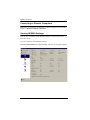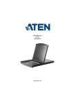
1
Virtual VNC Console KE8220 User Manual www.aten.com KE8220 User Manual FCC Information KE8220 Virtual VNC Console This is an FCC Class A product. In a domestic environment this product may cause radio interference in which case the user may be required to take adequate measures. This equipment has been tested and found to comply with the limits for a Class A digital device, pursuant to Part 15 of the FCC Rules. These limits are designed to provide reasonable protection against harmful interference when the equipment is operated in a commercial environment. This equipment generates, uses and can radiate radio frequency energy and, if not installed and used in accordance with the instruction manual, may cause harmful interference to radio communications. Operation of this equipment in a residential area is likely to cause harmful interference in which case the user will be required to correct the interference at his own expense. ii KE8220 User Manual Wireless-G USB Adapter The United States Federal Communication Commission (FCC) and the Canadian Department of Communications have established certain rules governing the use of electronic equipment. Part15, Class B This device complies with Part 15 of FCC rules. Operation is subject to the following two conditions: 1. This device may not cause harmful interface, and 2. This device must accept any interface received, including interface that may cause undesired operation. This equipment has been tested and found to comply with the limits for a Class B digital device, pursuant to Part 15 of the FCC Rules. These limits are designed to provide reasonable protection against harmful interference in a residential installation. This equipment generates, uses and can radiate radio frequency energy, and if not installed and used in accordance with the instructions, may cause harmful interference to radio communications. However, there is no guarantee that interference will not occur in a particular installation. If this equipment does cause harmful interference to radio or television reception, which can be determined by turning off and on, the user is encouraged to try to correct the interference by one or more of the following measures: Reorient or relocate the receiving antenna. Increase the distance between the equipment and receiver. Connect the equipment into an outlet on a circuit different from that to which the receiver is connected. CAUTION: 1. To comply with FCC RF exposure compliance requirements, a separation distance of at least 20 cm must be maintained between the antenna of this device and all persons. 2. This transmitter must not be co-located or operating in conjunction with any other antenna or transmitter. iii KE8220 User Manual RoHS This product is RoHS compliant. SJ/T 11364-2006 The following contains information that relates to China. iv KE8220 User Manual User Information Online Registration Be sure to register your product at our online support center: International North America http://support.aten.com ATEN TECH http://www.aten-usa.com/product_registration ATEN NJ http://support.aten.com Telephone Support For telephone support, call this number: International North America 886-2-8692-6959 ATEN TECH 1-888-999-ATEN ATEN NJ 1-732-356-1703 User Notice All information, documentation, and specifications contained in this manual are subject to change without prior notification by the manufacturer. The manufacturer makes no representations or warranties, either expressed or implied, with respect to the contents hereof and specifically disclaims any warranties as to merchantability or fitness for any particular purpose. Any of the manufacturer's software described in this manual is sold or licensed as is. Should the programs prove defective following their purchase, the buyer (and not the manufacturer, its distributor, or its dealer), assumes the entire cost of all necessary servicing, repair and any incidental or consequential damages resulting from any defect in the software. The manufacturer of this system is not responsible for any radio and/or TV interference caused by unauthorized modifications to this device. It is the responsibility of the user to correct such interference. The manufacturer is not responsible for any damage incurred in the operation of this system if the correct operational voltage setting was not selected prior to operation. PLEASE VERIFY THAT THE VOLTAGE SETTING IS CORRECT BEFORE USE. v KE8220 User Manual Package Contents The KE8220 package consists of: 1 KE8220 Virtual VNC Console 1 Wireless-G USB Adapter 1 Software CD 1 Power Adapter 1 Rack Mount Kit 1 User Manual* 1 Quick Start Guide Check to make sure that all of the components are present and in good order. If anything is missing, or was damaged in shipping, contact your dealer. Read this manual thoroughly and follow the installation and operation procedures carefully to prevent any damage to the KE8220 or to any other devices on the installation. * Features may have been added to the KE8220 since this manual was printed. Please visit our website to download the most up to date version of the manual. Copyright © 2008 ATEN® International Co., Ltd. Manual Part No. PAPE-0274-2AXG Printing Date: 05/2008 Altusen and the Altusen logo are registered trademarks of ATEN International Co., Ltd. All rights reserved. All other brand names and trademarks are the registered property of their respective owners. vi KE8220 User Manual Contents FCC Information . . . . . . . . . . . . . . . . . . . . . . . . . . . . . . . . . . . . . . . . . . . . . ii KE8220 Virtual VNC Console . . . . . . . . . . . . . . . . . . . . . . . . . . . . . . . . ii Wireless-G USB Adapter. . . . . . . . . . . . . . . . . . . . . . . . . . . . . . . . . . . .iii RoHS. . . . . . . . . . . . . . . . . . . . . . . . . . . . . . . . . . . . . . . . . . . . . . . . . . . . . iv SJ/T 11364-2006. . . . . . . . . . . . . . . . . . . . . . . . . . . . . . . . . . . . . . . . . . . . iv User Information . . . . . . . . . . . . . . . . . . . . . . . . . . . . . . . . . . . . . . . . . . . . . v Online Registration . . . . . . . . . . . . . . . . . . . . . . . . . . . . . . . . . . . . . . . . v Telephone Support . . . . . . . . . . . . . . . . . . . . . . . . . . . . . . . . . . . . . . . . v User Notice . . . . . . . . . . . . . . . . . . . . . . . . . . . . . . . . . . . . . . . . . . . . . . v Package Contents. . . . . . . . . . . . . . . . . . . . . . . . . . . . . . . . . . . . . . . . . . . vi About This Manual . . . . . . . . . . . . . . . . . . . . . . . . . . . . . . . . . . . . . . . . . . . x Overview . . . . . . . . . . . . . . . . . . . . . . . . . . . . . . . . . . . . . . . . . . . . . . . . x Conventions . . . . . . . . . . . . . . . . . . . . . . . . . . . . . . . . . . . . . . . . . . . . xi Product Information. . . . . . . . . . . . . . . . . . . . . . . . . . . . . . . . . . . . . . . . . . xi Chapter 1. Introduction Overview . . . . . . . . . . . . . . . . . . . . . . . . . . . . . . . . . . . . . . . . . . . . . . . . . . . 1 Features . . . . . . . . . . . . . . . . . . . . . . . . . . . . . . . . . . . . . . . . . . . . . . . . . . . 3 Requirements . . . . . . . . . . . . . . . . . . . . . . . . . . . . . . . . . . . . . . . . . . . . . . . 5 KE8220 Virtual VNC Console . . . . . . . . . . . . . . . . . . . . . . . . . . . . . . . . 5 Remote Computers . . . . . . . . . . . . . . . . . . . . . . . . . . . . . . . . . . . . . . . . 5 Cables . . . . . . . . . . . . . . . . . . . . . . . . . . . . . . . . . . . . . . . . . . . . . . . . . . 5 Operating Systems . . . . . . . . . . . . . . . . . . . . . . . . . . . . . . . . . . . . . . . . 5 Components . . . . . . . . . . . . . . . . . . . . . . . . . . . . . . . . . . . . . . . . . . . . . . . . 6 KE8220 Front View . . . . . . . . . . . . . . . . . . . . . . . . . . . . . . . . . . . . . . . . 6 KE8220 Rear View . . . . . . . . . . . . . . . . . . . . . . . . . . . . . . . . . . . . . . . . 7 Wireless-G USB Adapter. . . . . . . . . . . . . . . . . . . . . . . . . . . . . . . . . . . . 7 Chapter 2. Hardware Setup Desktop and Rack Mounting . . . . . . . . . . . . . . . . . . . . . . . . . . . . . . . . . . . . 9 Rack Mounting . . . . . . . . . . . . . . . . . . . . . . . . . . . . . . . . . . . . . . . . . . . 9 Installing the KE8220 Virtual VNC Console . . . . . . . . . . . . . . . . . . . . . . . 11 Installing a PS/2 Keyboard and Mouse . . . . . . . . . . . . . . . . . . . . . . . . 12 Installing the Wireless-G USB Adapter . . . . . . . . . . . . . . . . . . . . . . . . 12 Verifying the Connections . . . . . . . . . . . . . . . . . . . . . . . . . . . . . . . . . . . . . 13 Ethernet . . . . . . . . . . . . . . . . . . . . . . . . . . . . . . . . . . . . . . . . . . . . . . . . 13 Wi-Fi . . . . . . . . . . . . . . . . . . . . . . . . . . . . . . . . . . . . . . . . . . . . . . . . . . 13 Power . . . . . . . . . . . . . . . . . . . . . . . . . . . . . . . . . . . . . . . . . . . . . . . . . 13 vii KE8220 User Manual Chapter 3. Basic Operation The KE8220 Main Screen. . . . . . . . . . . . . . . . . . . . . . . . . . . . . . . . . . . . . 15 Logging In . . . . . . . . . . . . . . . . . . . . . . . . . . . . . . . . . . . . . . . . . . . . . . . . . 16 Graphical On-screen Display (OSD). . . . . . . . . . . . . . . . . . . . . . . . . . . . . 17 Connecting to Remote Computers . . . . . . . . . . . . . . . . . . . . . . . . . . . . . . 18 Viewing KE8220 Settings . . . . . . . . . . . . . . . . . . . . . . . . . . . . . . . . . . . . . 18 Configuring Local System Settings. . . . . . . . . . . . . . . . . . . . . . . . . . . . . . 19 Setting the System Name . . . . . . . . . . . . . . . . . . . . . . . . . . . . . . . . . . 19 Setting the Display Language . . . . . . . . . . . . . . . . . . . . . . . . . . . . . . . 20 Setting the Keyboard Layout. . . . . . . . . . . . . . . . . . . . . . . . . . . . . . . . 20 Setting the Resolution . . . . . . . . . . . . . . . . . . . . . . . . . . . . . . . . . . . . . 21 Setting the Hotkey. . . . . . . . . . . . . . . . . . . . . . . . . . . . . . . . . . . . . . . . 21 Setting Standby Mode. . . . . . . . . . . . . . . . . . . . . . . . . . . . . . . . . . . . . 22 Setting the Video Push Options . . . . . . . . . . . . . . . . . . . . . . . . . . . . . 23 User Management . . . . . . . . . . . . . . . . . . . . . . . . . . . . . . . . . . . . . . . . . . 24 Adding a User . . . . . . . . . . . . . . . . . . . . . . . . . . . . . . . . . . . . . . . . . . . 25 Editing a User . . . . . . . . . . . . . . . . . . . . . . . . . . . . . . . . . . . . . . . . . . . 26 Deleting a User . . . . . . . . . . . . . . . . . . . . . . . . . . . . . . . . . . . . . . . . . . 26 Configuring Network Settings . . . . . . . . . . . . . . . . . . . . . . . . . . . . . . . . . . 27 Configuring a Router, Gateway, or Firewall . . . . . . . . . . . . . . . . . . . . 27 Configuring Ethernet Settings . . . . . . . . . . . . . . . . . . . . . . . . . . . . . . . 28 Configuring Wireless Network Settings. . . . . . . . . . . . . . . . . . . . . . . . 29 Ad-Hoc Mode . . . . . . . . . . . . . . . . . . . . . . . . . . . . . . . . . . . . . . . . . . . 31 Configuring TCP/IP Settings in Ad-Hoc Mode. . . . . . . . . . . . . . . . 31 Configuring the KE8220 as a Server in Ad-Hoc Mode . . . . . . . . . 31 Infrastructure Mode . . . . . . . . . . . . . . . . . . . . . . . . . . . . . . . . . . . . . . . 32 Configuring TCP/IP Settings in Infrastructure Mode . . . . . . . . . . . 32 Connecting to APs or Wireless Devices in Infrastructure Mode . . 33 Logging Out . . . . . . . . . . . . . . . . . . . . . . . . . . . . . . . . . . . . . . . . . . . . . . . 33 Chapter 4. AltusenVNC Operation Overview. . . . . . . . . . . . . . . . . . . . . . . . . . . . . . . . . . . . . . . . . . . . . . . . . . 35 Downloading the AltusenVNC Executable . . . . . . . . . . . . . . . . . . . . . . . . 36 Installing AltusenVNC on Remote Computers . . . . . . . . . . . . . . . . . . . . . 37 Starting AltusenVNC. . . . . . . . . . . . . . . . . . . . . . . . . . . . . . . . . . . . . . . . . 44 Closing AltusenVNC . . . . . . . . . . . . . . . . . . . . . . . . . . . . . . . . . . . . . . . . . 44 Installing the AltusenVNC Service . . . . . . . . . . . . . . . . . . . . . . . . . . . . . . 45 Removing the AltusenVNC Service . . . . . . . . . . . . . . . . . . . . . . . . . . . . . 45 Configuring AltusenVNC. . . . . . . . . . . . . . . . . . . . . . . . . . . . . . . . . . . . . . 46 Configuring AltusenVNC Settings . . . . . . . . . . . . . . . . . . . . . . . . . . . . 46 Pushing Video to the KE8220. . . . . . . . . . . . . . . . . . . . . . . . . . . . . . . . . . 48 Uninstalling AltusenVNC. . . . . . . . . . . . . . . . . . . . . . . . . . . . . . . . . . . . . . 49 viii KE8220 User Manual Chapter 5. Remote Computer Operation Remote Computer Connection . . . . . . . . . . . . . . . . . . . . . . . . . . . . . . . . . 51 Connecting to Remote Computers . . . . . . . . . . . . . . . . . . . . . . . . . . . 51 Disconnecting Remote Computers . . . . . . . . . . . . . . . . . . . . . . . . . . . 53 Remote Computer Display and Control . . . . . . . . . . . . . . . . . . . . . . . . . . 54 The VNC Console . . . . . . . . . . . . . . . . . . . . . . . . . . . . . . . . . . . . . . . . 54 Switching Between the Graphical OSD and VNC Console . . . . . . . . . 54 Full Screen mode . . . . . . . . . . . . . . . . . . . . . . . . . . . . . . . . . . . . . . . . 54 Picture-in-Picture (PiP) Mode . . . . . . . . . . . . . . . . . . . . . . . . . . . . . . . 56 Panel Array Mode . . . . . . . . . . . . . . . . . . . . . . . . . . . . . . . . . . . . . . . . 57 Ctrl-Alt-Delete . . . . . . . . . . . . . . . . . . . . . . . . . . . . . . . . . . . . . . . . . . . 57 Remote Computer Management. . . . . . . . . . . . . . . . . . . . . . . . . . . . . . . . 58 Adding Remote Computers . . . . . . . . . . . . . . . . . . . . . . . . . . . . . . . . . 58 Editing Remote Computers . . . . . . . . . . . . . . . . . . . . . . . . . . . . . . . . . 60 Deleting Remote Computers . . . . . . . . . . . . . . . . . . . . . . . . . . . . . . . . 60 Chapter 6. Upgrading KE8220 and AltusenVNC Downloading Upgrade Files . . . . . . . . . . . . . . . . . . . . . . . . . . . . . . . . . . . 61 Upgrading KE8220 Firmware . . . . . . . . . . . . . . . . . . . . . . . . . . . . . . . . . . 62 Upgrading AltusenVNC . . . . . . . . . . . . . . . . . . . . . . . . . . . . . . . . . . . . . . . 64 Appendix Safety Instructions. . . . . . . . . . . . . . . . . . . . . . . . . . . . . . . . . . . . . . . . . . . 65 General . . . . . . . . . . . . . . . . . . . . . . . . . . . . . . . . . . . . . . . . . . . . . . . . 65 Rack Mounting . . . . . . . . . . . . . . . . . . . . . . . . . . . . . . . . . . . . . . . . . . 67 Technical Support . . . . . . . . . . . . . . . . . . . . . . . . . . . . . . . . . . . . . . . . . . . 68 International. . . . . . . . . . . . . . . . . . . . . . . . . . . . . . . . . . . . . . . . . . . . . 68 North America . . . . . . . . . . . . . . . . . . . . . . . . . . . . . . . . . . . . . . . . . . . 68 Specifications . . . . . . . . . . . . . . . . . . . . . . . . . . . . . . . . . . . . . . . . . . . . . . 69 KE8220 . . . . . . . . . . . . . . . . . . . . . . . . . . . . . . . . . . . . . . . . . . . . . . . . 69 Wireless-G USB Adapter. . . . . . . . . . . . . . . . . . . . . . . . . . . . . . . . . . . 69 Factory Default Settings . . . . . . . . . . . . . . . . . . . . . . . . . . . . . . . . . . . . . . 70 KE8220 . . . . . . . . . . . . . . . . . . . . . . . . . . . . . . . . . . . . . . . . . . . . . . . . 70 AltusenVNC. . . . . . . . . . . . . . . . . . . . . . . . . . . . . . . . . . . . . . . . . . . . . 70 Resetting the KE8220 . . . . . . . . . . . . . . . . . . . . . . . . . . . . . . . . . . . . . . . . 71 Restoring Factory Default Settings . . . . . . . . . . . . . . . . . . . . . . . . . . . . . . 71 Limited Warranty . . . . . . . . . . . . . . . . . . . . . . . . . . . . . . . . . . . . . . . . . . . . 72 ix KE8220 User Manual About This Manual This User Manual is provided to help you get the most from your KE8220 system. It covers all aspects of installation, configuration and operation. An overview of the information found in the manual is provided below. Overview Chapter 1, Introduction, introduces you to the KE8220. It presents the KE8220’s purpose and features, and describes the components of the KE8220’s front and back panels. Chapter 2, Hardware Setup, provides step-by-step instructions for installing the KE8220. Chapter 3, Basic Operation, explains how to configure and operate the KE8220. Chapter 5, Remote Computer Operation, explains how to connect, display and manage remote computers with the KE8220. Chapter 4, AltusenVNC Operation, explains how to install, configure, and operate AltusenVNC. Chapter 6, Upgrading KE8220 and AltusenVNC, explains how to upgrade the KE8220 firmware and AltusenVNC software. An Appendix, at the end of the manual provides technical and troubleshooting information. x KE8220 User Manual Conventions This manual uses the following conventions: Monospaced Indicates text that you should key in. [] Indicates keys you should press. For example, [Enter] means to press the Enter key. If keys need to be chorded, they appear together in the same bracket with a plus sign between them: [Ctrl+Alt]. 1. Numbered lists represent procedures with sequential steps. ♦ Bullet lists provide information, but do not involve sequential steps. → Indicates selecting the option (on a menu or dialog box, for example), that comes next. For example, Start → Run means to open the Start menu, and then select Run. Indicates critical information. Product Information For information about all ALTUSEN products and how they can help you connect without limits, visit ALTUSEN on the Web or contact an ALTUSEN Authorized Reseller. Visit ALTUSEN on the Web for a list of locations and telephone numbers: International North America http://www.aten.com ATEN TECH http://www.aten-usa.com ATEN NJ http://www.aten.com xi KE8220 User Manual This Page Intentionally Left Blank xii Chapter 1 Introduction Overview The KE8220 Virtual VNC Console is a thin-client device for managing remote computers running AltusenVNC. The KE8220 and AltusenVNC employ a client-server model to transmit a remote computer’s desktop environment over a network to the KE8220. By connecting a keyboard, video, mouse (KVM) console to the KE8220, you can access and manage up to 4 remote computers at a time just as if you were sitting right in front of them. The KE8220 also is useful for meeting room environments where laptop computers abound. Presenters can connect to the KE8220 to display their computers’ desktops on the attached monitor or projector. This eliminates plugging and unplugging of video cables and hardware incompatibility issues, so presentations progress more quickly and smoothly. The monitor, keyboard, and mouse connect to the KE8220 via an HDB-15 port and 2 universal serial bus (USB) ports. Or, you can use an ATEN PS/2 to USB Adapter to connect a PS/2 keyboard and mouse. The KE8220 operates over standard TCP/IP connections, so you can use your existing network infrastructure. Or, install the included Wireless-G USB Adapter to connect to 802.11b/g wireless networks. Finding, adding, and accessing remote computers is easy. The KE8220 automatically searches the local network for remote computers running AltusenVNC. You also can manually add computers or scan a broader range of IP addresses and ports for remote computers running AltusenVNC. The KE8220 stores connection information for up to 256 remote computers for quick and easy access. User management is equally simple. You can add up to 64 user accounts and assign administration rights to users at anytime. The KE8220 includes rich multi-language features such as multiple display languages and support for keyboard layouts for several languages and regions. 1 KE8220 User Manual Robust security is another feature of the KE8220. Login password authentication and two-level user access control prevent unauthorized users from accessing the KE8220 and making changes. Remote computers are password protected and passwords are encrypted in all network communications. On wireless networks, the KE8220 supports up to 256-bit Wired Equivalent Privacy (WEP) encryption to thwart eavesdropping. Additional features include a kit to mount the KE8220 to a ceiling, wall, or system rack, and free lifetime upgrades for both the KE8220 firmware and AltusenVNC software. 2 Chapter 1. Introduction Features Features Supports high-quality video display resolutions up to SXGA (1280 x 1024) @ 60 Hz Supports VGA standby mode with password protection on resume User-friendly graphical on-screen display menus for easy configuration Supports two-level user access control (Administrator and User) Password protected for enhanced security Display KE8220 and AltusenVNC user interface text in multiple languages Automatically discover KE8220 and AltusenVNC within the same network AltusenVNC is compatible with Windows 2000/XP/2003/Vista Choose from among several keyboard layouts Supports 10/100Base-T (802.3/802.3u) Ethernet Supports KE8220 operation over 802.11b/g wireless networks at speeds up to 54 Mbps Supports 64-bit, 128-bit, and 256-bit WEP encryption Supports static and automatic (DHCP) network configuration Free firmware upgrades via AltusenVNC over a network Native support for USB keyboard and mouse Supports PS/2 keyboard and mouse with ATEN PS/2-to-USB adapter Mounts easily to ceilings, walls, tabletops, and system racks (0U) 3 KE8220 User Manual Meeting Room Projection Enables wireless presentation without cable swapping Display computer's screen on projector via network without distance limitation Real-time display of presentations, images and applications Seamlessly switch focus between computers with a single mouse click Compatible with all projectors and display devices having standard VGA connectors Executable AltusenVNC software downloadable from the KE8220 embedded web server – enables real time presentations No Access Point required – AD-HOC mode with DHCP server support enables a direct wireless connection between the KE8220 and a laptop PC Remote Access Control remote computers from a KVM console anywhere at any time “Picture in picture” display lets you control one remote computer while monitoring another Panel Array Mode allows you to monitor up to 4 remote computers simultaneously from a single console Passwords encrypted network communications Manage up to 256 remote computers and 64 user accounts from one screen Supports Ctrl-Alt-Delete when AltusenVNC is running as a service 4 Chapter 1. Introduction Requirements The following is a list of requirements for the KE8220 installation. KE8220 Virtual VNC Console The following equipment is required for the KE8220 Virtual VNC Console: An XGA, or SXGA monitor or projector USB keyboard and mouse; or, PS/2 keyboard and mouse (requires ATEN PS/2-to-USB adapter) The KE8220 supports the following keyboard layouts: English (United Kingdom) English (United States) French German Italian Japanese Korean Spanish Remote Computers Remote computers must have the following: AltusenVNC software installed (installation or executable version) Connection to the network and a valid IP address Cables The KE8220 requires 1 Cat 5 cable to connect to your Ethernet network. Operating Systems AltusenVNC is compatible with Microsoft Windows 2000 and higher. 5 KE8220 User Manual Components KE8220 Front View 1 No. 1 Component RESET Button 2 3 4 5 Description Pressing in this button for 3 seonds and then releasing it performs a system reset. After the reset is completed you can login again. Note: This button is semi-recessed and must be pushed with a thin object — such as the end of a paper clip or a ballpoint pen. 6 2 WLAN LED The 10/100 Mbps LED lights orange to indicate 11 Mbps data transmission speed. It lights green for 54 Mbps. 3 10/100 Mbps LED The 10/100 Mbps LED lights orange to indicate 10 Mbps data transmission speed. It lights green for 100 Mbps. 4 LINK LED When you connect to a remote computer, the green LINK LED illuminates, and it blinks during data transfer. 5 POWER LED Lights (green) to indicate that the unit is receiving power and when it is in standby mode (orange). Chapter 1. Introduction KE8220 Rear View 1 No. 2 3 Component 4 Description 1 Power Jack The plug from the AC power adapter connects here. 2 Console Ports The external console's keyboard, monitor, and mouse cables plug in here. 3 WLAN Port The Wireless-G USB Adapter that links the KE8220 to a wireless network plugs in here. 4 LAN Port The Cat 5 cable that links the KE8220 to a network plugs in here. Wireless-G USB Adapter 2 1 No. Component Description 1 USB Connector Plugs into the WLAN Port on the KE8220 rear panel. 2 Cap Protects the USB connector when it is disconnected from the KE8220. 7 KE8220 User Manual This Page Intentionally Left Blank 8 Chapter 2 Hardware Setup 1. Important safety information regarding the placement of this device is provided on page 65. Please review it before proceeding. 2. Ensure that all equipment to be connected is powered off. 3. Make sure that all devices you will be connecting up are properly grounded. Desktop and Rack Mounting You can place the KE8220 on the desktop, or rack mount it to a system rack, ceiling, or wall. The KE8220 requires 0U of rack space. Rack Mounting A rack mount kit is included with the KE8220 to mount it to a system rack, ceiling, or wall. The following steps show how to rack mount the KE8220; however, you can follow this procedure to mount it to any flat surface. To rack mount the KE8220: 1. Using a Phillips head hex screwdriver, remove the screws (total 2) from the bottom of the KE8220 (as shown in the figure below). (Continues on next page.) 9 KE8220 User Manual (Continued from previous page.) 2. Using the screws provided with the rack mount kit, attach the mounting bracket to the bottom of the KE8220 (as shown in the figure below). 3. Attach the unit to the rack. Rack screws and cage nuts are not provided with the KE8220. Position the KE8220 so that the holes in the mounting bracket line up with those in the rack. Secure the mounting bracket to the rack with rack screws and cage nuts suitable for your rack. Alternatively, you can use screws of appropriate diameter and length to mount the mounting bracket to a ceiling, wall, or desktop (mounting screws not provided). 10 Chapter 2. Hardware Setup Installing the KE8220 Virtual VNC Console You will need the following items to install the KE8220 Virtual VNC Console: 1 display device (monitor or projector) 1 keyboard 1 mouse 1 Cat 5 cable an Ethernet connection an AC power source rated for the KE8220 To install the KE8220 Virtual VNC Console: 1. Connect the display device, USB keyboard, and USB mouse cables to the console ports. The ports are marked with a monitor, keyboard, or mouse icon. Or, if you wish to use a PS/2 keyboard and mouse, see Installing a PS/2 Keyboard and Mouse, page 12. Note: If you are installing a wireless keyboard and mouse that share the same wireless receiver, and the receiver has a USB connector, connect it to the keyboard port on the back of the KE8220. The port is marked with a keyboard icon. 2. Connect one end of a Cat 5 cable to your Ethernet network and the other end to the LAN port on the back of the KE8220. Or, if you wish to use the KE8220 on a wireless network, see Installing the Wireless-G USB Adapter, page 12. 3. Plug the power adapter into an appropriate AC power source, and then plug the power adapter cable into the power jack on the back of the KE8220. 11 KE8220 User Manual Installing a PS/2 Keyboard and Mouse Install an ATEN PS/2-to-USB Adapter (see footnote on page 5) if you want to use a PS/2 keyboard and/or mouse. After installing the adapter, you can still use a USB mouse, but you will not be able to use a USB keyboard unless you first remove the adapter. To install the PS/2 keyboard and mouse: 1. Connect the PS/2 keyboard and mouse cables to the keyboard and mouse ports on the adapter. The ports are color-coded and are marked with a keyboard or mouse icon. 2. Connect the adapter’s USB cable to the keyboard port on the back of the KE8220. The keyboard port is marked with a keyboard icon. Installing the Wireless-G USB Adapter Install the Wireless-G USB Adapter if you want to use the KE8220 on a wireless network. To install the Wireless-G USB Adapter: 1. Remove the cover from the KE8220’s WLAN port. 2. Remove the cap from the Wireless-G USB Adapter. 3. Using moderate pressure, insert the Wireless-G USB Adapter into the WLAN port. Ensure that the USB connector seats properly in the USB port. 12 Chapter 2. Hardware Setup Verifying the Connections Ethernet The 10/100 Mbps LED indicator on the front panel of the KE8220 illuminates when the KE8220 establishes a valid connection to the Ethernet network. It indicates when you are communicating at the 10 Mbps rate (orange) and the 100 Mbps rate (green). Wi-Fi The WLAN LED indicator on the front panel of the KE8220 illuminates when the KE8220 connects to a wireless LAN. It indicates when you are communicating at the 11 Mbps rate (orange) and the 54 Mbps rate (green). Power The Power LED on the front panel of the KE8220 illuminates when the KE8220 is powered. It indicates when the KE8220 is powered (green) and when it is in standby mode (orange). 13 KE8220 User Manual This Page Intentionally Left Blank 14 Chapter 3 Basic Operation The KE8220 Main Screen When you connect a keyboard, mouse and monitor to the KE8220, the Main Screen appears with the ALTUSEN logo and the LAN / WLAN IP address of the KE8220. After connecting the KE8220 to your network and configuring its network settings (see page 27), you can enter the new IP address into your computer’s web browser to access the KE8220’s web page and download a copy of the AltusenVNC executable file to run on your computer.1 Click anywhere on the Main Screen and the KE8220 Login dialog box appears. 1. See p. 35 for a description of the different versions of AltusenVNC. 15 KE8220 User Manual Logging In After you finish installing the KE8220, you can log in to the graphical onscreen display (OSD). A default administrator account is provided to set up the initial working environment for the KE8220. The default administrator account username and password are: Username: administrator1 Password: password Enter a valid username and password, and click Login. (If you want to clear the username and password information, click Reset.) After you login, we suggest that you change the default administrator account password. Otherwise, unauthorized users may be able to access the KE8220 through the default administrator account. (To change account passwords, see Editing a User, page 26.) 1. 16 Usernames and passwords are case sensitive. Chapter 3. Basic Operation Graphical On-screen Display (OSD) After logging into the KE8220, the graphical on-screen display (OSD) appears. The OSD allows you to connect to remote computers, add users, and modify KE8220 system settings. A menu bar is located on the left side of the OSD. Click on a menu button to display its related dialog boxes and options. Menus and dialog boxes are explained in the table below. Menu Dialog Box Action Remote Computers Connect Allows users to connect to remote computers and add, edit, and delete remote computers from the list. Users also can scan the network for remote computers. Local System Overview Provides an overview of the KE8220 settings. General Sets the system name, display language, keyboard layout, resolution, hotkey, standby mode, and video push options. User Management Allows administrators to manage users. LAN Configures the TCP/IP settings for the KE8220 on your Ethernet network. Wireless Configures the KE8220 for deployment on a wireless LAN. Logout Logs users out of the KE8220. 17 KE8220 User Manual Connecting to Remote Computers Information on connecting the KE8220 to remote computers can be found in Chapter 5, Remote Computer Operation. Viewing KE8220 Settings You can view a summary of the KE8220 settings, as well as the current firmware version. To view a summary of the KE8220 settings: From the Local System menu, select Overview. The Overview dialog box appears. 18 Chapter 3. Basic Operation Configuring Local System Settings KE8220 system settings are configured from the General dialog box. To open the General dialog box: From the Local System menu, select General. The General dialog box appears. Setting the System Name The KE8220 uses the system name to identify itself to remote computers. To set the system name for the KE8220: 1. From the Local System menu, select General. The General dialog box appears. 2. Under System, type a system name for the KE8220. System names can be up to 20 characters long. 3. Click Apply. 19 KE8220 User Manual Setting the Display Language Choose from among the following languages to display text in the KE8220 graphical OSD: English, German, Japanese, or Traditional Chinese. The default display language is English. To set the display language: 1. From the Local System menu, select General. The General dialog box appears. 2. In the Display Language drop-down list, select the language that you wish to use to display text in the KE8220 graphical OSD. 3. Click Apply. 4. In the dialog box that appears, click Yes if you want the new display language to take effect immediately. Setting the Keyboard Layout The KE8220 recognizes the following keyboard layouts: English (U.K.), English (U.S.), French, German, Italian, Japanese, Korean, and Spanish. Choose the layout of the keyboard that was connected during installation. The default keyboard layout is English (U.S.). Note: The KE8220 recognizes only ASCII characters. Foreign language characters will not display correctly. To set the keyboard layout: 1. From the Local System menu, select General. The General dialog box appears. 2. In the Keyboard Layout drop-down list, select the layout of the keyboard that you connected to the KE8220 during installation. 3. Click Apply. 20 Chapter 3. Basic Operation Setting the Resolution You can set the output resolution to be optimized for a display device connected to the KE8220. To set the resolution: 1. From the Local System menu, select General. The General dialog box appears. 2. In the Resolution drop-down list, select the resolution that best suits the display device connected to the KE8220. Select from: XGA (1024 x 768) @ 60 Hz (default) XGA (1024 x 768) @ 75 Hz WXGA (1280 x 768) @ 60 Hz WXGA (1280 x 768) @ 75 Hz SXGA (1280 x 1024) @ 60 Hz. 3. Click Apply. 4. In the dialog box that appears, click Yes if you want the new display resolution to take effect immediately. Setting the Hotkey You can use the hotkey to switch between the graphical OSD and the VNC console. The default hotkey is [Scroll Lock, Scroll Lock]. To set the hotkey: 1. From the Local System menu, select General. The General dialog box appears. 2. Under Hotkey, select either Scroll Lock, Scroll Lock or Ctrl, Ctrl. 3. Click Apply. 21 KE8220 User Manual Setting Standby Mode You can enable standby mode, which will turn off video to the display device if the user is idle for too long. You also can choose to password protect the KE8220 upon resuming from standby mode. When the KE8220 is in standby mode, the Power LED on the front panel of the KE8220 illuminates (red). The KE8220 automatically exits standby mode when there is mouse or keyboard input. To enable standby mode: 1. From the Local System menu, select General. The General dialog box appears. 2. Select Standby after and enter the number of minutes after which the KE8220 should standby if there is no input from the user. 3. Select On resume, password protect to require the user to enter a password when resuming after standby mode. 4. Click Apply. To disable standby mode: 1. From the Local System menu, select General. The General dialog box appears. 2. Click to clear the Standby after check box. 3. Click Apply. 22 Chapter 3. Basic Operation Setting the Video Push Options You can set how the KE8220 responds when a second computer uses AltusenVNC to push video to the KE8220 while another computer is already pushing video to the KE8220. Available options are: Override first video stream – the second video stream pushed to the KE8220 overrides the first. This is the default option. Alert second video stream – an alert displays on the monitor connected to the KE8220 when pushing a second video stream; you can switch to or cancel the second video stream. Deny second video stream – denies access of a second video stream to the KE8220. To set the Video Push option: 1. From the Local System menu, select General. The General dialog box appears. 2. Under Video Push Options, select one of the options listed above. 23 KE8220 User Manual User Management Administrators can add up to 64 users to the KE8220. The KE8220 stores the username and password for each user. Administrators can also edit user settings or delete a user. Once users have been added, they can use their usernames and passwords to login to the KE8220. When adding and editing users, administrators can choose whether users have administrative privileges. Administrators can configure settings for the KE8220, manage user accounts, and upgrade the KE8220 firmware. You can add, edit, and delete users from the User Management dialog box. To open the User Management dialog box: From the Local System menu, select User Management. The User Management dialog box appears. 24 Chapter 3. Basic Operation Adding a User To add a user: 1. From the Local System menu, select User Management. The User Management dialog box appears. 2. Under Users, click Add. The Add New User dialog box appears. 3. Type a name for the user. Usernames can be from 6 to 16 characters long. Legal characters include: a–z, A–Z, 0–9, space, hyphen, and underscore. Usernames are case sensitive. 4. Type a password for the user. Passwords can be from 8 to 16 characters long. Passwords are case sensitive. 5. Confirm that the password was typed correctly by typing it again. 6. Select whether the user is an administrator. 7. Click OK to finish adding the user, or click Cancel to cancel the operation. 25 KE8220 User Manual Editing a User To edit a user: 1. From the Local System menu, select User Management. The User Management dialog box appears. 2. Under Users, click to select a user, and then click Edit (or double-click on a user). The Edit User dialog box appears. 3. Edit the user settings that you wish to change. Leave the password fields blank to keep the same password. 4. Click OK to save your changes, or click Cancel to cancel the operation. Deleting a User To delete a user account: 1. From the Local System menu, select User Management. The User Management dialog box appears. 2. Under Users, click to select the user that you wish to delete. 3. Click Delete. The Confirm User Delete dialog box appears. 4. Click Yes to delete the user, or click No to cancel the operation. 26 Chapter 3. Basic Operation Configuring Network Settings The KE8220 uses standard TCP/IP protocol to communicate with computers. You can attach the KE8220 to your Ethernet network via the LAN port, or install the Wireless-G USB Adapter to connect to a wireless LAN. You can choose to configure the KE8220’s TCP/IP properties manually, or dynamically assign them using Dynamic Host Configuration Protocol (DHCP). Configuring a Router, Gateway, or Firewall You may need to open the following ports in your router, gateway, or firewall1. This will ensure that the KE8220 can communicate properly with remote computers that have AltusenVNC installed. TCP ports: 1352, 1353, and 6998 (depends on remote computer setting) UDP ports: 1352 1. Windows Vista users must open these ports in the Windows Firewall. 27 KE8220 User Manual Configuring Ethernet Settings To configure the TCP/IP settings for the Ethernet connection: 1. From the Local System menu, select LAN. The LAN dialog box appears. 2. Under Internet Protocol (TCP/IP), choose Obtain an IP address automatically (DHCP). Or, choose Use the following static IP address, and then manually enter the IP address, subnet mask, and default gateway. If you are unsure, ask your network administrator for the correct settings. 3. Click Apply. 28 Chapter 3. Basic Operation Configuring Wireless Network Settings You can find wireless devices and connect to a wireless network. Wireless network settings are configured from the Wireless dialog box. To open the Wireless dialog box: From the Local System menu, select Wireless. The Wireless dialog box appears. After you install the Wireless-G USB Adapter, the KE8220 searches for access points (AP) and other wireless devices. It displays information about the wireless devices it discovers in the Network list. Select a device from the Network list to display detailed information about it in the fields below. You can update the list at any time by clicking Refresh. If a wireless device does not broadcast its Service Set Identifier (SSID), it will not appear in the Network list. However, you can still associate with such devices by manually configuring their settings. 29 KE8220 User Manual The table below describes the Wireless Network settings: Item Description SSID Service Set Identifier – displays the unique name associated with the wireless LAN. The SSID is identical for each device or station on the wireless LAN. Mode Displays the operating mode of the wireless network: Infrastructure: The KE8220 communicates with other wireless devices and the wired network through an access point (AP). Ad-Hoc: The KE8220 communicates directly with other wireless devices without the use of an AP. Channel Displays the channel used for data transmission. Encryption Displays whether the wireless device requires Wired Equivalent Privacy (WEP) encryption. Signal Displays the strength of the signal from the AP or wireless device. Status Displays the status of the KE8220’s connection to the wireless network: Connected: The KE8220 is associated with an AP or wireless device. Disconnected: The KE8220 is not associated with an AP or wireless device. Refresh Clicking Refresh updates the Network list. Connect Clicking Connect tries to associate the KE8220 with the AP or wireless device that you selected or manually configured. When switching to another AP, the WEP key of new AP should be input. Save Configuration If selected, the AP’s settings are permanently saved. If the KE8220 is powered off, it will automatically try to associate with the same AP when it is powered on again. Key Format Allows you to select the WEP key format: Hexadecimal: The WEP key consists of alphanumeric characters 0–9 and A–F. ASCII: The WEP key consists of 7-bit ASCII characters. Key Length 30 Allows you to select the WEP key length: 64 bit, 128 bit, or 256 bit. Chapter 3. Basic Operation Ad-Hoc Mode In Ad-Hoc mode, computers connect directly to the KE8220 without needing an access point. In this case, the KE8220 acts as a server which computers connect to. Because of this, the KE8220 IP address cannot be obtained dynamically using DHCP; instead, the KE8220 IP address must be set manually. With DHCP server mode automatically activated in Ad-Hoc mode, the start and end IP address range, as specified in the DHCP Server section of Internet Protocol (TCP/IP), can be set.1 This range represents the maximum number of IP addresses that can be automatically assigned to computers connecting to the KE8220. Configuring TCP/IP Settings in Ad-Hoc Mode To configure the TCP/IP settings for the wireless network in Ad-Hoc mode: 1. From the Local System menu, select Wireless. The Wireless dialog box appears. 2. Under Internet Protocol (TCP/IP), manually enter the IP address, subnet mask, default gateway, start IP, and end IP. If you are unsure, ask your network administrator for the correct settings, or simply leave the default settings. 3. If necessary, click Apply. Configuring the KE8220 as a Server in Ad-Hoc Mode To configure the KE8220 as a server in Ad-Hoc mode: 1. Make sure the Wireless-G USB Adapter is attached to the KE8220. 2. From the Local System menu, select Wireless. The Wireless dialog box appears. 3. In the fields provided under Wireless Network, enter the settings for the KE8220: a) Type the SSID for the KE8220. b) Select Ad-Hoc as the wireless networking mode. c) Enter the channel. 1. The first three parts of the IP address are configured in the IP Address text box; only the last part of the IP address can be set for the start and end of the range. 31 KE8220 User Manual 4. Enabling WEP encryption for the KE8220 is optional. a) If WEP encryption is enabled, select the key length and format. b) In the field provided, enter the WEP key. (The WEP key format and number of characters required are displayed under the field. The number of characters already entered is displayed to the right of the field.) 5. If you want to use these settings permanently, select Save Configuration. 6. Click Connect. The status displays the SSID Name - Connected. 7. Use your computer’s list of wireless network connections to connect to the KE8220. Infrastructure Mode In Infrastructure mode, computers connect to the KE8220 using an access point (AP). The AP may also be connected to a cabled network and the Internet which can be used by the KE8220 to connect to local and remote computers. In this case, the KE8220 does not acts as a server (the DHCP Server section of Internet Protocol (TCP/IP) is disabled), but is simply another node on the network which computers can connect to. Because of this, the KE8220 IP address can be obtained dynamically using DHCP, or set manually. Configuring TCP/IP Settings in Infrastructure Mode To configure the TCP/IP settings for the wireless network in Infrastructure mode: 1. From the Local System menu, select Wireless. The Wireless dialog box appears. 2. Under Internet Protocol (TCP/IP), choose Obtain an IP address automatically (DHCP). Or, choose Use the following static IP address, and then manually enter the IP address, subnet mask, and default gateway. If you are unsure, ask your network administrator for the correct settings. 3. Click Apply. 32 Chapter 3. Basic Operation Connecting to APs or Wireless Devices in Infrastructure Mode To associate with an access point (AP) or other wireless device: 1. From the Network list, select the AP or wireless device with which you wish to associate. If you want to use the default settings provided by the AP, skip to Step 3. If you want to change the default settings, or the AP, or the wireless device you wish to associate with does not appear in the list, go to Step 2. 2. In the fields provided, enter the settings for the AP or wireless device: a) Type the SSID for your wireless network. b) Select Infrastructure as the wireless networking mode. c) Enter the channel. 3. If the AP or wireless device requires WEP encryption, enable it. 4. Select the WEP encryption key length and format. 5. In the field provided, enter the WEP key. (The WEP key format and number of characters required are displayed under the field. The number of characters already entered is displayed to the right of the field.) 6. If you want to use these settings permanently, select Save Configuration. 7. Click Connect. The KE8220 will try to associate with the AP or wireless device. If the KE8220 is successful, the status will change to Connected. Logging Out When you are finished using the KE8220, click Logout to exit. 33 KE8220 User Manual This Page Intentionally Left Blank 34 Chapter 4 AltusenVNC Operation Overview AltusenVNC is a program that runs on Windows-based remote computers. It enables up to 127 KE8220 at a time to connect to a remote computer and control it.1 Additionally, a remote computer running AltusenVNC can push video to a KE8220. AltusenVNC captures video from the remote computer and sends it to the KE8220, while keyboard and mouse input from the KE8220 is captured and sent to the remote computer. Two versions of AltusenVNC are shipped with the KE8220. One version is built into the KE8220 and is available as an executable download file from the KE8220. This version of AltusenVNC is not a full installation package and is used for creating temporary connections to the KE8220 – meeting room presentations are ideal for downloading the AltusenVNC executable file. Another version of the AltusenVNC software is available from the installation CD provided with the KE8220. This version of AltusenVNC can be configured to run as a service or an application and is ideal for computers that need to be monitored remotely and accessed anytime using the KE8220, even after the computer has been shutdown and restarted. 1. Performance depends upon the remote computer's hardware configuration and the network's load capacity. When more than one KE8220 users connect to a remote computer, they share the keyboard and mouse. 35 KE8220 User Manual Downloading the AltusenVNC Executable If you do not know the IP address of the KE8220, use the following steps to download the AltusenVNC executable file: 1. Connect a monitor/display device to the KE8220 (connecting a keyboard and mouse is optional), connect the KE8220 to a LAN or insert the wireless LAN adapter into the KE8220, and then connect the power adapter to the KE8220 to power it on. 2. Log in to the OSD (see page 16) and change the IP address to one that is appropriate for the network that the KE8220 resides on. See Configuring Network Settings, page 27, for more details. 3. Ensure that your computer is connected to a LAN/WAN and enter the IP address into your computer's web browser to access the KE8220 webpage and download a copy of the AltusenVNC executable file. 4. Save the file to any location on your computer. 5. Double-click the saved file to start AltusenVNC. If you know the IP address of the KE8220, use the following steps to download the AltusenVNC executable file: 1. Connect the KE8220 to a LAN or insert the wireless LAN adapter into the KE8220 and connect the power adapter to the KE8220 to power it on. 2. Ensure that your computer is connected to a LAN/WAN and enter the IP address into your computer's web browser to access the KE8220 webpage and download a copy of the AltusenVNC executable file. 3. Save the file to any location on your computer. 4. Double-click the saved AltusenVNC executable file to start AltusenVNC. When you are finished using the AltusenVNC executable file, simply delete it to completely remove AltusenVNC from your computer. To configure AltusenVNC, see page 46 for details. 36 Chapter 4. AltusenVNC Operation Installing AltusenVNC on Remote Computers Install AltusenVNC on remote computers that you want to access from the KE8220. AltusenVNC comes with an unlimited license, so you can install it on as many remote computers as necessary. During installation, choose whether to install AltusenVNC as a service or an application. If you install AltusenVNC as a service, it starts when Windows is booted and continues to run in the background. It is a good idea to install AltusenVNC as a service if the remote computer must be accessible whenever the operating system is running. Also, when you install AltusenVNC as a service, KE8220 users can use the Ctrl-Alt-Delete command on the remote computer. If you choose to install AltusenVNC as an application, you will need to manually start it each time and KE8220 users will not be able to use the CtrlAlt-Delete command on the remote computer. You should install AltusenVNC as an application if you will use it only occasionally, such as on a laptop computer to push video to the KE8220. During installation, you will be asked to choose the language that AltusenVNC will use to display user interface text once the installation is complete. If you wish to change the display language, you must reinstall AltusenVNC. You may need to open certain ports in your router, gateway, or firewall to ensure that AltusenVNC can communicate properly with the KE8220. To see which ports are used, see Configuring a Router, Gateway, or Firewall, page 271. Note: Installing AltusenVNC as a service may not be supported for some Windows operating systems. Please check our Website to see if support has been added to a newer version of AltusenVNC. 1. Windows Vista users must open these ports in the Windows Firewall. 37 KE8220 User Manual To install AltusenVNC on a remote computer: 1. Insert the KE8220 installation CD into the CD drive of the computer you want to install AltusenVNC and wait a few seconds for the installation program to autostart.1 2. If you previously installed AltusenVNC and are not installing a newer version, the following dialog box appears requiring your confirmation: 3. Click Yes to continue. Or, click No to cancel. If you clicked Yes, the Setup AltusenVNC dialog box appears. 1. 38 If the installation program fails to start, use your computer’s file browser to navigate to the CD drive and double-click the AltusenVNC.exe installation file. Chapter 4. AltusenVNC Operation 4. Click Next. The following dialog box appears: 5. Read and accept the license agreement, and then click Next. The following dialog box appears: (Continues on next page.) 39 KE8220 User Manual (Continued from previous page.) 6. Select the installation folder, and then click Next. The following dialog box appears: 7. Select the Start Menu folder in which you wish the program’s shortcut created, and then click Next. The following dialog box appears: 40 Chapter 4. AltusenVNC Operation 8. Select the type of installation, and then click Next. Note: Installing AltusenVNC as a service may not be supported for some Windows operating systems. If it is not supported for your system, this option will be unavailable. Please check our Website to see if support has been added to a newer version of AltusenVNC. The following dialog box appears: (Continues on next page.) 41 KE8220 User Manual (Continued from previous page.) 9. Select the language that you wish to use to display text in AltusenVNC, and then click Next. The following dialog box appears: 10. Select whether to add an AltusenVNC shortcut icon on the Desktop and click Next. The following dialog box appears: 42 Chapter 4. AltusenVNC Operation 11. Click Install. After AltusenVNC installs on your computer, the following dialog box appears: 12. Click Finish to exit Setup. If you selected Start AltusenVNC, the AltusenVNC Settings dialog box appears. (Continues on next page.) 43 KE8220 User Manual (Continued from previous page.) Note: By default, the computer’s name is displayed in the Name field. You can change the name by selecting the field and typing in a new name. The KE8220 uses this name, and the computer’s IP address, to identify the computer on a network. See Configuring AltusenVNC Settings, page 46. 13. Type in a password and click OK. The AltusenVNC installation is complete. Starting AltusenVNC If you installed AltusenVNC as an application, do the following to start it: From the Start menu, select Programs > AltusenVNC > AltusenVNC. The AltusenVNC icon will appear in the notification area of the taskbar indicating that it is running and displaying your computer’s IP address. If you installed AltusenVNC as a service, do the following to start it: Restart the computer. After the computer restarts, AltusenVNC will run as a service. The AltusenVNC icon will appear in the notification area of the taskbar. Closing AltusenVNC To close AltusenVNC, click the AltusenVNC icon in the notification area of the taskbar, and select Exit. If you installed AltusenVNC as a service, the next time you reboot the computer the AltusenVNC service will also start. To completely remove the service and prevent AltusenVNC from starting the next time Windows is booted, see Removing the AltusenVNC Service, page 45. 44 Chapter 4. AltusenVNC Operation Installing the AltusenVNC Service Installing AltusenVNC as a service may not be supported for all versions of Windows. If you are unable to install AltusenVNC as a service, please check our Website to see if a newer version of AltusenVNC supports this feature for your version of Windows. To install the AltusenVNC service: 1. From the Start menu, select Programs > AltusenVNC > AltusenVNC (Service Mode) > Install AltusenVNC Service. The following dialog box appears. 2. Click OK. 3. Restart the computer. After the computer restarts, AltusenVNC will run as a service. The AltusenVNC icon will appear in the notification area of the taskbar. Removing the AltusenVNC Service To remove the AltusenVNC service: 1. From the Start menu, select Programs > AltusenVNC > AltusenVNC (Service Mode) > Remove AltusenVNC Service. The following dialog box appears. 2. Click OK. The AltusenVNC service is removed. 45 KE8220 User Manual Configuring AltusenVNC If AltusenVNC was installed properly and is running, the AltusenVNC icon will appear in the notification area of the taskbar. Icon Description A red screen indicates that AltusenVNC is running. A blue screen indicates that AltusenVNC is running and at least one KE8220 is connected. Configuring AltusenVNC Settings Before using AltusenVNC the first time you must configure the settings.1 Note: You can only use ASCII characters to type text in AltusenVNC. To configure the AltusenVNC settings: 1. Click the AltusenVNC icon in the notification area of the taskbar. A popup menu appears. 2. From the pop-up menu, select Settings. The AltusenVNC Settings dialog box appears. 1. 46 Configuration of AltusenVNC installation and executable versions is the same. Chapter 4. AltusenVNC Operation 3. Enter a name for the remote computer. Remote computer names can be up to 16 characters long. By default, the computer’s name is displayed. You can change the name by selecting the field and typing in a new name. The KE8220 uses this name, and the computer’s IP address, to identify the computer on a network. 4. Type a password for the remote computer. Passwords can be up to 8 characters long. Users must enter this password when connecting to the remote computer from the KE8220. 5. Under Network, type the port that AltusenVNC will use to communicate with the KE8220. If you don’t have any reason to change this, use the default port setting (6998). 6. Under View Settings: Select Match KE8220 Display Resolution if you wish AltusenVNC to resize the remote computer’s display resolution to match that of the KE8220 when they are connected. After the connection is ended, the remote computer’s display resolution will revert to the original setting. Matching the display resolutions enables KE8220 users to view the remote computer’s entire desktop environment in Full Screen mode without scroll bars. Select Remove Wallpaper for KE8220 to remove the remote computer’s wallpaper from the KE8220’s display. Removing wallpaper improves performance by reducing the amount of processing power and network bandwidth required to transmit the remote computer’s display to the KE8220. Select Capture Alpha Blending to display the remote computer’s alpha blending on the KE8220’s display. Note: Enable Capture Alpha Blending to improve the display of computers running Windows Vista. 7. Click OK to save your changes. Or, click Cancel to close the dialog box without saving changes. 47 KE8220 User Manual Pushing Video to the KE8220 You can push video to a KE8220 from a remote computer running AltusenVNC. When you push video, AltusenVNC initiates a connection to the KE8220 to display the remote computer’s desktop environment on the display device connected to the KE8220. Connections to KE8220 start from the Push Video to KE8220 dialog box. To open the Push Video to KE8220 dialog box: 1. Double-click the AltusenVNC icon in the notification area of the taskbar. The Push Video to KE8220 dialog box appears. The Push Video to KE8220 dialog box lists all KE8220 that have been discovered automatically. If the KE8220 that you wish to connect to is not listed, you can still connect to it by entering the IP address. The dialog box also indicates the status of each KE8220: Status Description Ready The KE8220 is ready to accept connections from remote computers. Busy The KE8220 is in use, but you may still try to connect. See Setting the Video Push Options, page 23 for details. 48 Chapter 4. AltusenVNC Operation To push video from the remote computer to a KE8220: 1. Double-click the AltusenVNC icon in the notification area of the taskbar. The Push Video to KE8220 dialog box appears. 2. Enter the KE8220's IP address, or select the KE8220 from the list. 3. Click Connect. Depending on the Video Push option selected in the graphical OSD (see Setting the Video Push Options, page 23), a dialog box may appear on the KE8220 user’s screen requesting that the user accept or refuse the connection. If the KE8220 user does not respond within 10 seconds, the attempt to connect is aborted. If the connection is successful, the color of the AltusenVNC icon will change to blue and the remote computer’s desktop environment will appear on the KE8220 display device. Or, click Cancel to close the dialog box without connecting to the KE8220. 4. Click Disconnect to close the connection to the KE8220. Uninstalling AltusenVNC To uninstall AltusenVNC: 1. From the Start menu, select Programs > AltusenVNC > Unistall AltusenVNC. 2. Click Yes and OK when prompted. AltusenVNC service is removed. 49 KE8220 User Manual This Page Intentionally Left Blank 50 Chapter 5 Remote Computer Operation Remote Computer Connection Connecting to Remote Computers You can connect up to 4 remote computers at one time to the KE8220 through a LAN, WLAN, or the Internet. AltusenVNC must be properly configured and running on remote computers that you wish to connect to. You will need the IP address, port, and password that were entered when AltusenVNC was configured on the remote computer. (To configure AltusenVNC on remote computers, see Installing AltusenVNC on Remote Computers, page 37, for details.) All connections to remote computers start from the Connect dialog box. To open the Connect dialog box: Select the Remote Computers menu. The Connect dialog box appears. 51 KE8220 User Manual The Connect dialog box is divided into two areas: Connections to remote computers are initiated in the Connect to Remote Computers area. The Manage Remote Computers area stores remote computers that have been added to the KE8220 automatically, manually, or through scanning the network. It also provides information about the status of the remote computers and how they were added. The table below describes the remote computer information. Column Description Name Displays the name of the remote computer (if one has been given). IP Address Displays the IP address of the remote computer. Port Displays the port that the KE8220 uses to communicate with the remote computer. Type Auto: Remote computers that are running AltusenVNC and lie within the same subnet as the KE8220 are automatically discovered and added. Scan: Remote computers that were discovered through scanning the network. Manual: Remote computers that were manually added. Status Displays the current status of the remote computer: Ready: The remote computer is ready to accept connections. Busy: At least one other user is connected to the remote computer. If you connect now, you will share the connection with the other user(s). Unknown: The KE8220 cannot determine the status of the remote computer. To connect to one or more remote computers: 1. Select the Remote Computers menu. The Connect dialog box appears. 2. Under Connect to Remote Computers, enter a remote computer’s IP address, port, and password on a single line. (If the remote computer that you wish to connect to has already been added to the KE8220, select it from either the Name or IP Address drop-down lists. The port is entered automatically.) 3. Repeat this procedure for each remote computer that you wish to connect to. You can connect to up to 4 remote computers at a time. 52 Chapter 5. Remote Computer Operation 4. Click the check box next to each remote computer that you wish to connect to. Or, choose Select All to connect to all 4 remote computers at once. 5. Click Connect. The KE8220 VNC Console appears. Disconnecting Remote Computers You can manually disconnect all remote computers at the same time by clicking the X in the upper right corner of the VNC Console. (This feature is not available in Full Screen mode.) Or, follow the procedure below to manually disconnect remote computers one at a time. Note: Remote computers are automatically disconnected when you logout and when you replace them with new connections to remote computers in the Connect dialog box. To manually disconnect a remote computer: 1. Click the red triangle at the bottom right corner of the window for the remote computer that you want to disconnect. A pop-up menu appears. 2. From the pop-up menu, select Disconnect. The remote computer is disconnected. 53 KE8220 User Manual Remote Computer Display and Control The VNC Console The VNC Console displays the remote computers and allows you to control them. Each remote computer appears in a separate window within the VNC Console. (If you cannot see the remote computer’s full display, use the scroll bars to scroll up and down and side to side until you can see the relevant portion of the screen.) Switching Between the Graphical OSD and VNC Console You can use the hotkey to switch between the VNC Console and the graphical OSD, and back again. The connection to the remote computer will not be affected by switching between the graphical OSD and the VNC console. To switch between the VNC Console and graphical OSD: 1. Press the selected hotkey twice within 1 second. The display will switch between the VNC Console and graphical OSD. 2. Press the hotkey twice again to switch back to the previous screen. Full Screen mode Full Screen mode is the default display mode when connecting to 1 remote computer. In this mode, you can control the remote computer just as if you were sitting right in front of it. In addition, window borders are removed and the remote computer is displayed at the maximum resolution possible. 54 Chapter 5. Remote Computer Operation You also can change the display mode to Picture-in-Picture mode (for 2 remote computers); or, you can cascade or tile the windows. If you wish to change the display mode, you must first disable Full Screen mode (see below). There are two ways to enable Full Screen mode. You can double-click on the window that you want to make full screen. Or, follow the procedure described below. To enable Full Screen mode: 1. If Picture-in-Picture (PiP) mode is enabled, disable it. 2. Click the red triangle at the bottom right corner of the window for which you wish to enable Full Screen mode. A pop-up menu appears. 3. From the pop-up menu, select Full Screen. Full Screen mode is enabled. To disable Full Screen mode: 1. Click the red triangle at the bottom right corner of the window. A pop-up menu appears. 2. From the pop-up menu, select Full Screen. Full Screen mode is disabled and the remote computer windows are tiled. To switch to PiP mode, see Picture-in-Picture (PiP) Mode below. To cascade or tile remote computer windows, see Panel Array Mode, page 57. 55 KE8220 User Manual Picture-in-Picture (PiP) Mode Picture-in-Picture (PiP) mode is the default display mode when connecting to 2 remote computers. PiP mode lets you to control a remote computer while monitoring another. In PiP mode, one remote computer displays in a full-size window, while the other remote computer displays in a smaller window at the bottom right corner of the screen. The full-size window is the active window. To swap the windows in which the remote computers appear, double-click on the smaller window. You also can change the display mode to Full Screen mode; or, you can cascade or tile the windows. If you wish to change the display mode, you must first disable PiP mode (see below). To enable PiP mode: 1. If Full Screen mode is enabled, disable it. 2. Click the red triangle at the bottom right corner of the window that you want to make smaller. A pop-up menu appears. 3. From the pop-up menu, select PIP. PiP mode is enabled. Note: You can enable PiP mode only when connected to 2 remote computers. To disable PiP mode: 1. Click the red triangle at the bottom right corner of the window. A pop-up menu appears. 56 Chapter 5. Remote Computer Operation 2. From the pop-up menu, click to clear PIP. PiP mode is disabled and the remote computer windows are tiled. To switch to Full Screen mode, see Full Screen mode, page 54. To cascade or tile remote computer windows, see Panel Array Mode, page 57. Panel Array Mode When you connect to 3 or 4 remote computers at a time, or you disable Full Screen mode or Picture-in-Picture (PiP) mode, the remote computer windows are tiled by default. To control a remote computer, you first must enable Full Screen mode for that window (see page 54). You also can enable Picture-in-Picture mode when connected to 2 remote computers. Note: 1. You cannot cascade or tile a window if you are connected to only 1 remote computer. 2. You can use the shortcut combination [Alt+W] to open the Window menu. To tile remote computers: From the Window menu, select Tile. The remote computer displays are tiled. To cascade remote computers: From the Window menu, select Cascade. The remote computer displays are cascaded. To horizontally tile remote computers: From the Window menu, select Tile Horizontally. The remote computer displays are tiled horizontally. To enable Full Screen mode, see Full Screen mode, page 54. To enable PiP mode, see Picture-in-Picture (PiP) Mode, page 56. Ctrl-Alt-Delete You can use the shortcut key combination [Ctrl-Alt-Delete] on remote computers for which you have installed the AltusenVNC service. See Installing the AltusenVNC Service, page 45. 57 KE8220 User Manual Remote Computer Management You can add up to 256 remote computers to the KE8220. The KE8220 stores the name, IP address, and port for each remote computer. At any time, you also can edit or delete remote computers. Once remote computers have been added, you only need choose them from a list and type the password to connect to them. Remote computers that are running AltusenVNC and lie within the same subnet as the KE8220 are automatically discovered and added to the KE8220. Remote computers that are added in this way cannot be edited or deleted. When manually adding or editing remote computers, verify that the IP address and port entered are the same in the KE8220 and AltusenVNC. Otherwise, the KE8220 will not be able to connect to the remote computer. Adding Remote Computers You can add remote computers manually or by scanning the network for remote computers running AltusenVNC. Up to 256 remote computers can be added in this way. To manually add a remote computer: 1. Select the Remote Computers menu. The Connect dialog box appears. 2. Under Manage Remote Computers, click Add. The Add New Remote Computer dialog box appears. 3. Type a name for the remote computer. Remote computer names can be up to 16 characters long. 58 Chapter 5. Remote Computer Operation 4. Type the IP address of the remote computer and the port that the KE8220 will use to communicate with AltusenVNC. If you are not sure which are the correct IP address and port, check the AltusenVNC settings on the remote computer. 5. Click OK to save your changes. Or, click Cancel to close the dialog box without saving changes. To scan the network for remote computers: 1. Select the Remote Computers menu. The Connect dialog box appears. 2. Under Manage Remote Computers, click Scan. The Scan for Remote Computers dialog box appears. 3. Under IP Addresses, type the beginning and ending IP addresses for the range that you wish to search. 4. Under Ports, type the beginning and ending ports for the range that you wish to search. 5. Click Scan to begin scanning the network for remote computers running AltusenVNC. When the KE8220 finishes scanning, it will inform you how many remote computers were found and add them to the Manage Remote Computers list. Or, click Cancel to close the dialog box without scanning the network. 59 KE8220 User Manual Editing Remote Computers You can edit the name, IP address, and port of remote computers that have been added manually or by scanning the network. Automatically discovered remote computers cannot be edited. To edit a remote computer: 1. Select the Remote Computers menu. The Connect dialog box appears. 2. Under Manage Remote Computers, click to select a remote computer, and then click Edit. Alternatively, you can double-click on a remote computer. The Edit Remote Computer dialog box appears. 3. Edit the remote computer settings that you wish to change. 4. Click OK to save your changes. Or, click Cancel to close the dialog box without saving changes. Deleting Remote Computers You can delete remote computers that have been added manually or by scanning the network. Automatically discovered remote computers cannot be deleted. To delete a remote computer: 1. Select the Remote Computers menu. The Connect dialog box appears. 2. Under Manage Remote Computers, click to select the remote computer that you wish to delete. 3. Click Delete. The Confirm Remote Computer Delete dialog box appears. 4. Click Yes to finish deleting the remote computer. Or, click No to cancel the operation. 60 Chapter 6 Upgrading KE8220 and AltusenVNC Downloading Upgrade Files As new versions of KE8220 firmware and AltusenVNC software become available, they are posted on our Website. Check the Website regularly to find the latest information and download upgrade files. To download a KE8220 firmware upgrade file: 1. Go to the download section of our Website. 2. Under Firmware, select KE8220. A list of available firmware upgrade files appears. 3. Choose the firmware upgrade file that you wish to install and download it to a computer running AltusenVNC. To download an AltusenVNC upgrade file: 1. Go to the download section of our Website. 2. Under Driver & Software, select AltusenVNC. A list of available upgrade files appears. 3. Choose the upgrade file that you wish to install and download it to the hard disk of the computer for which you wish to upgrade AltusenVNC. Or, you can download it to a removable drive or network drive accessible to the computer. 61 KE8220 User Manual Upgrading KE8220 Firmware Administrators can upgrade the KE8220’s firmware from a remote computer running AltusenVNC. To upgrade the KE8220 firmware: 1. Right-click on the AltusenVNC icon in the notification area of the taskbar. A pop-up menu appears. 2. From the pop-up menu, select Upgrade KE8220 Firmware.... The Upgrade KE8220 Firmware dialog box appears. The Upgrade KE8220 Firmware dialog box lists all KE8220 that have been discovered automatically. If the KE8220 for which you wish to upgrade firmware is not listed, you can still connect to it by entering the IP address. The dialog box also indicates the status of each KE8220: Status 62 Description Ready The KE8220 is ready for a firmware upgrade. Busy The KE8220 is in use. You can still upgrade firmware; however, the upgrade procedure may take longer to complete. Chapter 6. Upgrading KE8220 and AltusenVNC 3. Enter the username and password of an administrator on the KE8220 that you want to upgrade. 4. Enter the KE8220's IP address, or select the KE8220 from the list. 5. Click Upgrade. Or, click Cancel to abort the firmware upgrade. If you clicked Upgrade, the Open dialog box appears. 6. Navigate to the firmware upgrade file, select it, and then click Open. A dialog box appears that displays the current firmware version and the firmware upgrade version. 7. Click OK to proceed with the firmware upgrade. Or, click Cancel to abort the firmware upgrade. (Continues on next page.) 63 KE8220 User Manual (Continued from previous page.) After the firmware upgrade is complete, the following dialog box appears: 8. Click OK. The KE8220 will reboot. After it reboots, you can login to confirm that the firmware has been upgraded. Upgrading AltusenVNC To upgrade the AltusenVNC software: 1. Navigate to the directory where you saved the AltusenVNC upgrade file. 2. Double-click the AltusenVNC upgrade file. 3. Install AltusenVNC. For more information, see Installing AltusenVNC on Remote Computers, page 37. 64 Appendix Safety Instructions General Read all of these instructions. Save them for future reference. Follow all warnings and instructions marked on the device. Do not place the device on any unstable surface (cart, stand, table, etc.). If the device falls, serious damage will result. Do not use the device near water. Do not place the device near, or over, radiators or heat registers. The device cabinet is provided with slots and openings to allow for adequate ventilation. To ensure reliable operation, and to protect against overheating, these openings must never be blocked or covered. The device should never be placed on a soft surface (bed, sofa, rug, etc.) as this will block its ventilation openings. Likewise, the device should not be placed in a built in enclosure unless adequate ventilation has been provided. Never spill liquid of any kind on the device. Unplug the device from the wall outlet before cleaning. Do not use liquid or aerosol cleaners. Use a damp cloth for cleaning. The device should be operated from the type of power source indicated on the marking label. If you are not sure of the type of power available, consult your dealer or local power company. The device is designed for IT power distribution systems with 230V phase-to-phase voltage. To prevent damage to your installation it is important that all devices are properly grounded. The device is equipped with a 3-wire grounding type plug. This is a safety feature. If you are unable to insert the plug into the outlet, contact your electrician to replace your obsolete outlet. Do not attempt to defeat the purpose of the grounding-type plug. Always follow your local/national wiring codes. Do not allow anything to rest on the power cord or cables. Route the power cord and cables so that they cannot be stepped on or tripped over. (Continues on next page.) 65 KE8220 User Manual (Continued from previous page.) If an extension cord is used with this device make sure that the total of the ampere ratings of all products used on this cord does not exceed the extension cord ampere rating. Make sure that the total of all products plugged into the wall outlet does not exceed 15 amperes. To help protect your system from sudden, transient increases and decreases in electrical power, use a surge suppressor, line conditioner, or uninterruptible power supply (UPS). Position system cables and power cables carefully; Be sure that nothing rests on any cables. Never push objects of any kind into or through cabinet slots. They may touch dangerous voltage points or short out parts resulting in a risk of fire or electrical shock. Do not attempt to service the device yourself. Refer all servicing to qualified service personnel. If the following conditions occur, unplug the device from the wall outlet and bring it to qualified service personnel for repair. The power cord or plug has become damaged or frayed. Liquid has been spilled into the device. The device has been exposed to rain or water. The device has been dropped, or the cabinet has been damaged. The device exhibits a distinct change in performance, indicating a need for service. The device does not operate normally when the operating instructions are followed. Only adjust those controls that are covered in the operating instructions. Improper adjustment of other controls may result in damage that will require extensive work by a qualified technician to repair. 66 Appendix Rack Mounting Before working on the rack, make sure that the stabilizers are secured to the rack, extended to the floor, and that the full weight of the rack rests on the floor. Install front and side stabilizers on a single rack or front stabilizers for joined multiple racks before working on the rack. Always load the rack from the bottom up, and load the heaviest item in the rack first. Make sure that the rack is level and stable before extending a device from the rack. Use caution when pressing the device rail release latches and sliding a device into or out of a rack; the slide rails can pinch your fingers. After a device is inserted into the rack, carefully extend the rail into a locking position, and then slide the device into the rack. Do not overload the AC supply branch circuit that provides power to the rack. The total rack load should not exceed 80 percent of the branch circuit rating. Make sure that all equipment used on the rack – including power strips and other electrical connectors – is properly grounded. Ensure that proper airflow is provided to devices in the rack. Ensure that the operating ambient temperature of the rack environment does not exceed the maximum ambient temperature specified for the equipment by the manufacturer Do not step on or stand on any device when servicing other devices in a rack. 67 KE8220 User Manual Technical Support Technical support is available both by email and online (with a browser over the web): International Email Support Online Support [email protected] Technical Support http://support.aten.com Troubleshooting Documentation Software Updates http://www.aten.com Telephone Support 886-2-8692-6959 North America Email Support ATEN TECH [email protected] ATEN NJ Online Support Technical Support ATEN NJ Troubleshooting Documentation Software Updates Telephone Support [email protected] ATEN TECH http://www.aten-usa.com/support http://support.aten.com ATEN TECH http://www.aten-usa.com ATEN NJ http://www.aten.com ATEN TECH 1-888-999-ATEN ATEN NJ 1-732-356-1703 When you contact us, please have the following information ready beforehand: Product model number, serial number, and date of purchase. Your computer configuration, including operating system, revision level, expansion cards, and software. Any error messages displayed at the time the error occurred. The sequence of operations that led up to the error. Any other information you feel may be of help. 68 Appendix Specifications KE8220 Function Connectors Console Ports KE8220 Keyboard 1 x USB Type A Female (White) Video 1 x HDB-15 Female (Blue) Mouse 1 x USB Type A Female (White) Power 1 x DC Jack LAN 1 x RJ-45 Female WLAN 1 x USB Type A Female (White) Switches Reset 1 x Semi-recessed Pushbutton LEDs WLAN 1 (Orange/Green) 10/100 Mbps 1 (Orange/Green) Link 1 (Green) Power 1 (Green/Orange) Video 1280 x 1024 @ 60 Hz Power Consumption Environment DC 5.3V, 3.8W Operating Temp. 0–50° C Storage Temp. Physical Properties -20–60° C Humidity 0–80% RH, Non-condensing Housing Metal Weight 0.50 kg LxWxH 20.00 x 8.00 x 2.50 cm Wireless-G USB Adapter Function Specification USB Connector Wireless LAN LED 1 x USB Type A Male (White) Detecting Connected Power Consumption 1 (Orange) 1 (Blue) USB Bus Powered 69 KE8220 User Manual Factory Default Settings KE8220 Setting Default Default username and password Username: administrator Password: password System Name KE8220 + MAC address (For example: KE8220001122334455) Display Language English Keyboard Layout English (U.S.) Resolution XGA (1024 x 768) @ 60 Hz Hotkey [Scroll Lock] [Scroll Lock] Standby Mode Disabled Video Push Option Override first video stream LAN IP Address: 192.168.0.60 Subnet Mask: 255.255.255.0 Default Gateway: 192.168.0.254 MAC Address: 00:10:74:45:00:F8 Wireless Network SSID: ATEN-KE8220-00F8 Authentication: Auto Channel: 1 Mode: Ad-Hoc Encryption: None Key Format; Hexadecimal Key Length: 64 bits IP Address: 192.168.1.60 Subnet Mask: 255.255.255.0 Default Gateway: 192.168.1.254 DHCP Start IP: 192.168.1.70 DHCP End IP: 192.168.1.100 AltusenVNC Setting Communication port 70 Default 6998 Appendix Resetting the KE8220 Press the RESET button for at least 3 seconds, then release to reset the KE8220. Restoring Factory Default Settings You can restore the KE8220 settings back to their factory defaults. All local system settings will be reset, and all remote computers that have been scanned or manually added will be erased. Any users that were added will also be removed. To restore the KE8220’s factory default settings: 1. Disconnect the power adapter cable from the KE8220. 2. While pressing the RESET button, reconnect the power adapter cable to the KE8220. 3. Release the RESET button. After logging in, a message displays indicating that the factory default settings have been restored. 71 KE8220 User Manual Limited Warranty ALTUSEN warrants this product against defects in material or workmanship for a period of one (1) year from the date of purchase. If this product proves to be defective, contact ALTUSEN's support department for repair or replacement of your unit. ALTUSEN will not issue a refund. Return requests can not be processed without the original proof of purchase. When returning the product, you must ship the product in its original packaging or packaging that gives an equal degree of protection. Include your proof of purchase in the packaging and the RMA number clearly marked on the outside of the package. This warranty becomes invalid if the factory-supplied serial number has been removed or altered on the product. This warranty does not cover cosmetic damage or damage due to acts of God, accident, misuse, abuse, negligence or modification of any part of the product. This warranty does not cover damage due to improper operation or maintenance, connection to improper equipment, or attempted repair by anyone other than ALTUSEN. This warranty does not cover products sold AS IS or WITH FAULTS. IN NO EVENT SHALL ALTUSEN'S LIABILITY EXCEED THE PRICE PAID FOR THE PRODUCT. FURTHER, ALTUSEN SHALL NOT BE RESPONSIBLE FOR DIRECT, INDIRECT, SPECIAL, INCIDENTAL OR CONSEQUENTIAL DAMAGES RESULTING FROM THE USE OF THE PRODUCT, ITS ACCOMPANYING SOFTWARE, OR ITS DOCUMENTATION. ALTUSEN SHALL NOT IN ANY WAY BE RESPONSIBLE FOR, WITHOUT LIMITATION, LOSS OF DATA, LOSS OF PROFITS, DOWNTIME, GOODWILL, DAMAGE OR REPLACEMENT OF EQUIPMENT OR PROPERTY, AND ANY EXPENSES FROM RECOVERY, PROGRAMMING, AND REPRODUCTION OF ANY PROGRAM OR DATA. ALTUSEN makes no warranty or representation, expressed, implied, or statutory with respect to its products, contents or use of this documentation and all accompanying software, and specifically disclaims its quality, performance, merchantability, or fitness for any particular purpose. ALTUSEN reserves the right to revise or update its product, software or documentation without obligation to notify any individual or entity of such revisions, or update. For details about extended warranties, please contact one of our dedicated value added resellers. 72 Index A Adding Remote Computers, 58 Adding Users, 25 AltusenVNC Closing, 44 Configuring, 46 Installing on Remote Computers, 37 Starting, 44 upgrading, 64 AltusenVNC Service Installing, 45 Removing, 45 C Configure Ethernet Settings, 28 Firewall, 27 Gateway, 27 Local System Settings, 18 Network Settings, 27 Router, 27 Wireless Network Settings, 29 Connecting to Remote Computers, 31, 32, 51 Conventions, xi Ctrl-Alt-Delete, 37, 57 D default username and password, 16 Deleting Remote Computers, 60 Deleting Users, 26 Disconnecting Remote Computers, 53 E Editing Remote Computers, 60 Editing Users, 26 Ethernet Settings, 28 F Factory Default Settings, 70 Features, 3 firmware, upgrading, 62 Full Screen mode, 54 G Graphical OSD, 17 I Installation KE8220, 11 PS/2 Keyboard, 12 PS/2 mouse, 12 K KE8220 Front View, 6 Rear View, 7 upgrading firmware, 62 L logging in, 15, 51 Logging Out, 33 O Online Registration, v 73 P Package Contents, vi Panel Array Mode, 57 password, default, 16 Picture-in-Picture (PiP) Mode, 56 Pushing Video to the KE8220, 48 R Rack Mounting, 9 Requirements Cables, 5 KE8220 Virtual VNC Console, 5 Operating Systems, 5 Remote Computers, 5 Resetting, 71 Restoring Factory Default Settings, 71 RoHS, iv T Technical Support, 68 Telephone support, v U upgrading AltusenVNC, 64 KE8220 firmware, 62 User Notice, v username, default, 16 V Virtual VNC Console, 5 VNC Console, 54 W Wireless Network Settings, 29 Wireless-G USB Adapter, 7 S Safety Instructions General, 65 Rack Mounting, 67 Setting Standby Mode, 22 Setting the Display Language, 20 Setting the Hotkey, 21 Setting the Keyboard Layout, 20 Setting the System Name, 19 SJ/T 11364-2006, iv Specifications, 69 Switching Between the Graphical OSD and VNC Console, 54 74