Transcript
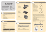
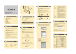
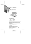
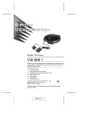
1
6
2
3
4
Hardware Installation 2
General
The General Page presents four items of information: Device Name,
MAC Address, Firmware Ver, Last IP from DHCP Server.
User Management
The User Management dialog box is used to create, delete and manage
user profiles. Up to 64 user profiles can be established.
5
6
7
8
KL9108 Dual Rail LCD KVM Switch Quick Start Guide
KL9116 Dual Rail LCD KVM Switch Quick Start Guide
®
© Copyright 2011 ATEN International Co., Ltd. www.aten.com
Altusen and the Altusen logo are trademarks of ATEN International Co., Ltd.
All rights reserved. All other trademarks are the property of their respective owners.
This product is RoHS compliant
PAPE-1214-R00G
Printing Date: 06/2011
Patent No.
TW I273415
TW 199673
TW I273372
TW I288595
TW I325748
TW I327054
US 7350091
US 7142721
US 7405926
US 7258568
US 7414853
US 7675742
GB 2425661
CN ZL 02129894.7
CN 200610079265.0
CN ZL 200520012462.1
CN ZL 200610007185.4
CN ZL 200610145931.6
Online Registration
International:
• http://support.aten.com
North America:
• http://www.aten-usa.com/product_registration
Technical Phone Support
International:
• 886-2-8692-6959
China:
• 86-10-5255-0110
Japan:
• 81-3-5615-5811
Korea:
• 82-2-467-6789
North America:
• 1-888-999-ATEN Ext: 4988
United Kingdom:
• 44-8-4481-58923
9
10
11
12
13
14
15
All information, documentation, and specifications contained in this media are subject to change without prior notification by the manufacturer.
Please visit our website to find the most up to date version.
1. (Optional) Connect the external console’s monitor, keyboard, and mouse to the console
ports on the rear panel of the KVM switch.
2. Using a KVM cable set, plug the custom SPHD connector into any available KVM port on
the switch.
3. At the other end of the cable, plug the keyboard, mouse and video cables into their
respective ports on the computer.
Repeat steps 2 and 3 for any additional computers you are installing.
4. Plug the LAN, WAN or Internet cable into the KL9108 / KL9116's RJ-45 socket.
5. Connect the power cord to the switch and to an AC power source appropriate for the
KL9108 / KL9116.
6. Power on the switch.
7. After the switch is powered on, power on the computers.
Note: Although the KL9116 is pictured in the diagram, the installation process is the same for
the KL9108.
16
5
3
2
1
4
Package Contents
The KL9108 / KL9116 package consists of:
1 KL9108 or KL9116 Dual Rail LCD KVM Switch with Standard Rack Mount Kit
2 Custom KVM Cable Sets
1 Power Cord
1 User Manual
1 Quick Start Guide
Network
RADIUS
If you are using a RADIUS server, RADIUS Configuration allows you to
set up its parameters.
Security
The Security page controls access to the KL9108 / KL9116.
Customization
The Customization dialog box is arranged in four major sections: Login
Failures, Working Mode, I/O, and Miscellaneous.
Date/Time
The Date/Time dialog box lets the Administrator set up the KL9108
/KL9116’s time parameters:
KL9108/KL9116 Unit (Rear View)
4
4. KVM Ports (CPU Ports)
5. External Console Section
6. LAN Port
1. Power Socket
2. Power Switch
3. PON Port
8
1
Note: For the sake of brevity only the KL9116 is pictured here. The front and rear panel
views are similar for the KL9108.
1
Optional Equipment
Depending on any optional equipment that you may have purchased, one of the following may
be included in your package:
• Standard Rack Mount Kit - Long
• Easy Installation Rack Mount Kit - Short
• Easy Installation Rack Mount Kit - Long
Service Configuration
Access Port
As a security measure, if a firewall is being used, the Administrator can
specify the port numbers that the firewall will allow, and set the firewall
accordingly.
Users must specify the port number when they log in to the KL9108 /
KL9116. If an invalid port number (or no port number) is specified, the
KL9108 / KL9116 will not be found.
Log Server
In this panel, you specify the MAC address and a port number for the
computer that the Log Server resides on.
The Network dialog is used to specify the KL9108 / KL9116’s network
environment.
IP Address
The KL9108 / KL9116 can either have its IP address assigned
dynamically (DHCP), or it can be given a fixed IP address.
DNS Server
You can set the KL9108 / KL9116 to automatically obtain the DNS
server address, or you can specify the primary and alternate DNS servers’
addresses.
2
3
Operation
An On Screen Display (OSD) interface governs KL9108 / KL9116 computer control and switching
operations. The OSD can be accessed remotely with a Windows-based client or a Java-based client.
You must log in via an Internet browser to connect to the KL9108 / KL9116 and to invoke the OSD.
4
7
Administrator Setup
To log in from an Internet browser:
1. Open the browser and specify the IP address of the KL9108 / KL9116 in the URL bar.
Note: If you don’t know the IP address, get it from the KL9108 / KL9116 administrator.
2. When the Security Alert dialog box appears, accept the certificate.
3. A login page appears
KL9116
5
2
Requirements
External Console
• A VGA, SVGA, or multisync monitor capable of displaying the highest resolution provided
by any computer in the installation
• PS/2 keyboard and mouse
Computers
The following equipment must be installed on each computer:
• A VGA, SVGA or multisync video graphics card with an HDB-15 port
• PS/2 mouse and keyboard ports (6-pin Mini-DIN)
Remote Computers
• For best results, computers that remotely access the KL9108 / KL9116 should have at least a
P III 1 GHz processor, with their screen resolution set to 1024 x 768.
• Users who want to access the KL9108 / KL9116 with the Windows Client must have DirectX
7.0 or higher installed.
• If you don't already have it, DirectX is available for free download from Microsoft's web site:
http://www.microsoft.com/downloads.
• Users who want to access the KL9108 / KL9116 with the Java Client must have Sun's Java 2
(1.4.2 or higher) runtime environment installed. Java is available for free download from the
Sun Java website:http://java.sun.com.
• Browsers must support 128-bit SSL encryption.
• For best results, a network transfer speed of at least 128 Kbps is recommended.
Cables
Use ATEN's high-quality, custom cables to ensure reliable switching among computers and
daisy chained switches.
3
6
5
Once the KL9108 / KL9116 has been installed, the next step that the Administrator needs to
perform is to set up the unit for user operation. The most convenient way to do this for the first
time is from the local console.
After the KL9108 / KL9116 turned on, a login prompt appears on the console monitor: Since
this is the first time you are logging in, use the default Username: administrator; and the
default Password: password.
After you have successfully logged in, the KL9108 / KL9116 Main Webpage appears with the
General dialog box displayed. You can click the Windows Client button (or Java Client
button) to activate the browser-based Windows Client OSD (or Java Client OSD).
KL9116
KL9116Login
Hardware Installation 1
Standard Rack Mounting
A standard rack mounting kit is provided with your KL9108/KL9116. The kit enables the switch to
be mounted in rack with a depth of 42 - 77 cm.
Note:
1. It takes two people to mount the switch: one to hold it in place; the other to screw it in.
2.Optional mounting kits - including single person Easy Installation kits – are available with
a separate purchase.
3. The standard rack mounting kit does not include screws or cage nuts. If you need additional
screws or cage nuts, contact your rack dealer
4. Provide a valid Username and Password (set up by the KL9108 / KL9116 administrator),
then Click Login to continue.
Mouse Setup
The following mouse setting procedures should be performed on each computer connected to the
KL9108/KL9116.
After you successfully log in, the Local Console OSD appears:
KL9116 Main
KL9116
KL9116
Windows Systems:
Note: You must use the generic mouse driver supplied with Windows.
* XP / Server 2003 -- middle position; Enhance pointer precision: off
* 2000 / ME -- Mouse motion: middle position; Acceleration: off
* NT / 98 / 95 -- Mouse speed: slowest
Sun / Linux Systems:
Open a terminal session and issue the following command:
* Sun: xset m 1
* Linux: xset m 0
1. Packing material has been inserted to protect the KL9108/KL9116 during shipping. Slide
the LCD module out until the packing material is visible. Remove the packing material before
installing the unit, as shown in the diagram below.
9
2. While one person positions the switch in the rack and holds it in place, the second person
loosely screws the front brackets to the rack.
KL9108/KL9116 Unit (Front View)
The OSD consists of four pages, each with a specific set of functions: Main, Configuration,
Administration, and Log.
1. The Main page governs port access. Selecting a port and double-clicking it switches you to
the device on that port.
2. The Configuration Page sets the operating parameters for each user.
3. The Log Page brings up the contents of the log file.
4. The Administration Page:
When you click the Administration tab, the Administration page comes up. Each of the
administrative functions is represented by an icon at the left of the page.
Computer
Connections
Console
Connections
Port Selection
KL9116
Function
Connectors
Switches
LEDs
1. Upper Handle
7. Touchpad
13. External Mouse Port
2. LCD Display
8. Lower Handle
14. Port Selection Area
Emulation
3. LCD Controls
9. Rack Mounting Tabs
15. Reset Switch
Video
4. Port LEDs
10. LCD Release Catch
16. Power LED
5. Keyboard
11. LCD On/Off Button
6. Keyboard Release Catch
12. Lock LEDs
KL9108
Direct
Max.
Local
Remote
External
Console Port
KL9116 General
KL9116
3.While the first person still holds the switch in place, the second person slides the L brackets into
the switch's side mounting brackets, from the rear until the bracket flanges contact the rack, then
screws the L brackets to the rack.
Specifications
8
64 (via Cascade)
Keyboard
Video
Mouse
KVM Port
External Mouse
Power
LAN
PON
Reset
Port Selection
Power
LCD Power
LCM Adjustment
On Line
Selected
Power
Num Lock
Caps Lock
Scroll Lock
Link
10 / 100 Mbps
Keyboard/Mouse
17” LCD
Remote
Scan Interval
I/P Rating
Power Consumption
Operating Temp.
Environment
Storage Temp.
Humidity
Housing
Physical
Weight
Properties
Dimensions (L x W x H)
4. After the L brackets have been secured, tighten the front bracket screws.
KL9116
16
128 (via Cascade)
1
1
OSD, Hotkey, Pushbutton
1 x 6-pin Mini-DIN Female (Purple)
1 x HDB-15 Female (Blue)
1 x 6-pin Mini-DIN Female (Green)
8 x SPHD-15 Female
16 x SPHD-15 Female
(Yellow)
(Yellow)
1 x 6-pin Mini-DIN Female (Green)
1 x 3-prong AC Socket
1 x RJ-45 Female (Black)
1 x DB-9 Male (Black)
1 x Semi-recessed Pushbutton
2 x Pushbutton
1 x Rocker
1 x Pushbutton
4 x Pushbutton
8 (Green)
16 (Green)
8 (Orange)
16 (Orange)
1 (Blue)
1 (Green)
1 (Green)
1 (Green)
1 (Green)
1 (Orange/Green)
PS/2
1280 x 1024@75Hz; DDC2B
1600 x 1200@60Hz; DDC2B
1–255 Seconds
100–240V AC; 50/60 Hz; 1A
120V/31W; 230V/39W
0–40°C
-20–60°C
0–80% RH, Non-condensing
Metal
17.10 kg
17.30 kg
70.50 x 48.20 x 4.40 cm
All specifications are subject to change without notice.