1
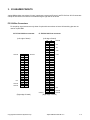
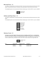
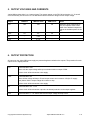
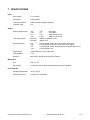
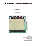
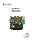
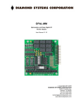
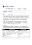
JUPITER-MM
DC/DC Power Supply PC/104 Module
User Manual V1.5
Copyright 2014
Diamond Systems Corporation
555 Ellis Street
Mountain View, CA 94043
Tel (650) 810-2500
Fax (650) 810-2525
[email protected]
www.diamondsystems.com
TABLE OF CONTENTS
1.
DESCRIPTION ....................................................................................................................................................3
2.
BOARD DRAWING .............................................................................................................................................4
3.
I/O HEADER PINOUTS .......................................................................................................................................5
PC/104 BUS CONNECTORS ............................................................................................................................5
MAIN INPUT POWER – J4 ................................................................................................................................6
AUXILIARY INPUT/OUTPUT POWER – J5...........................................................................................................6
SHUTDOWN CONTROL – J3 .............................................................................................................................6
4.
INSTALLATION ..................................................................................................................................................7
5.
OUTPUT VOLTAGES AND CURRENTS ...........................................................................................................8
6.
OUTPUT PROTECTION .....................................................................................................................................8
7.
SPECIFICATIONS...............................................................................................................................................9
Copyright 2012 Diamond Systems Corp.
Jupiter-MM User Manual V1.5
P. 2
JUPITER-MM
DC/DC Power Supply PC/104 Module
1. DESCRIPTION
JUPITER-MM is a PC/104-format power supply module designed for mobile as well as stationary embedded
applications. The JUPITER-MM is designed using a high efficiency DC/DC converter circuit to provide the
maximum power with minimum losses. Power supply performance and reliability have been optimized through the
use of precision surface mount components. The Jupiter-MM series contains significant advances in mobile embedded
power supply technology:
Surface Mount Components
To the maximum extent possible, surface mount components have been used in the design, to lower the
profile and improve ruggedness. An additional benefit to SMT technology is the improved ability to use the
PCB planes as a heat sink.
High Efficiency, High-Frequency Design
Efficiency is as high as 92 percent, lowering input power requirements as well as heat generation. The
200KHz switching circuit allows the use of smaller inductors, reducing size and weight and allowing the
board to fully fit within the PC/104 height requirements.
Advanced Heat Sink Technology
A new compressible thermally-conductive material mounted under the aluminum heat sink makes it
possible to wick heat away effectively from varying height components. Also, the use of surface mount
components and careful PCB design enhance the dissipation of heat through the PCB planes.
Remote On/Off Control
The supply can be turned on and off with an external contact closure through an auxiliary connector.
Extended Temperature Operation
o
o
Extended temperature (-40 C to +85 C) operation is standard, enabling the supplies to be used in vehicle applications
and other harsh environments.
Jupiter-MM is available in two standard configurations of output power and output voltages:
JMM-512
50W, +5/+12V outputs
JMM-512-V512
50W, +5/+12/-5/-12V outputs
Copyright 2012 Diamond Systems Corp.
Jupiter-MM User Manual V1.5
P. 3
2. BOARD DRAWING
J1
PC/104 8-bit bus header
J2
PC/104 16-bit bus header
J3
Shutdown control input
J4
Main power input
J5
Power input/output connector
Copyright 2012 Diamond Systems Corp.
Jupiter-MM User Manual V1.5
P. 4
3. I/O HEADER PINOUTS
Jupiter-MM provides connections for input, input/output, remote on/off control, and PC/104 bus. All I/O connectors
except the PC/104 bus connectors are located along the right side of the board.
PC/104 Bus Connectors
For simplicity, signal names are only shown for pins with connections on board. All remaining pins are not
used on Jupiter-MM.
J2: PC/104 8-bit bus connector
J1: PC/104 16-bit bus connector
(Left edge of board)
(Left edge of board)
Ground
+5V
Ground
Ground
D0
D1
D2
D3
D4
D5
D6
D7
D8
D9
D10
D11
D12
D13
D14
D15
D16
D17
D18
D19
C0
C1
C2
C3
C4
C5
C6
C7
C8
C9
C10
C11
C12
C13
C14
C15
C16
C17
C18
C19
Ground
Ground
(Right edge of board)
Copyright 2012 Diamond Systems Corp.
A1
A2
A3
A4
A5
A6
A7
A8
A9
A10
A11
A12
A13
A14
A15
A16
A17
A18
A19
A20
A21
A22
A23
A24
A25
A26
A27
A28
A29
A30
A31
A32
B1
B2
B3
B4
B5
B6
B7
B8
B9
B10
B11
B12
B13
B14
B15
B16
B17
B18
B19
B20
B21
B22
B23
B24
B25
B26
B27
B28
B29
B30
B31
B32
Ground
+5V
-5V
-12V
+12V
+5V
Ground
Ground
(Right edge of board)
Jupiter-MM User Manual V1.5
P. 5
Main Input Power – J4
J4 consists of a detachable 2-pin screw terminal block. The screw terminals will accept wire sizes from 18-28
gauge. The input polarity is shown in markings on the board adjacent to the board-mounted connector.
The detachable portion of the screw terminal is Phoenix Contact type no. MC1.5/2-ST-3.81, part no. 1803578.
1
2
Positive Input
Input Return
Auxiliary Input/Output Power – J5
J5 consists of a detachable 7-pin screw terminal block. The screw terminals will accept wire sizes from 18-28
gauge.
The detachable portion of the screw terminal is Phoenix Contact type no. MC1.5/7-ST-3.81, part no. 1803620.
1
2
3
4
5
6
7
Positive Input
Input Return
+12V Output
+5V Output
Ground
-5V Output
-12V Output
Shutdown Control – J3
Shutdown may be implemented by shorting the two pins on J3 together. J3 consists of a .1” spacing friction
lock header, Amp part no. 640457-2. The mating connector with integrated IDC contacts is included with the
board. It is also a stock item at Digi-Key (Tel 800-344-4539 in the US, or www.digikey.com). The part nos. for
several compatible mating connectors are shown below. Each contact is rated for 4A using 22AWG wire.
1
2
Item
Mating Connectors
Amp Part No.
640442-2
640441-2
640440-2
Copyright 2012 Diamond Systems Corp.
Shutdown input
Ground
Digi-Key Part No.
A19030
A1901
A1906
Description
26 AWG, Blue
24 AWG, White
22 AWG, Red
Jupiter-MM User Manual V1.5
P. 6
4. INSTALLATION
All JUPITER-MM power supplies are load tested prior to shipping. The supplies ship with all the external
connectors required to start using your supply immediately.
No user configuration is required for any version of Jupiter-MM. Simply plug in the input power and the supply is
operational. To power up your supply:
1. For protection, if you are unfamiliar with the use of this product, do not plug any other boards onto it when
powering it up for the first time.
2. Connect a DC source to Main power J4, or to the Auxiliary connector J5. The supply will operate with input
voltages from +7 to +34VDC.
CAUTION: Voltages above 35V will be shunted to ground through a transient voltage supressor
(TVS) on the board. The TVS is rated for 1,500 watt surges. However it could be damaged by
sustained voltages above 35V.
CAUTION: The supply is not protected against reverse polarity inputs. To add this protection
would dissipate excessive heat and power, reducing the efficiency. Check your wiring for correct
polarity before powering up the supply.
3. Once the input voltage is in the valid range, verify that the power output indicator LEDs in the lower left
corner are illuminated. This verifies your input power connections and the supply are fully functional. Note
that only indicators corresponding to the voltages available on the supply will be lit. On the dual output
version, the –5V and –12V LEDs may be present on the board but will not be lit.
4. Power down the supply. Plug the supply into your PC/104 stack. Your system is ready to use.
Copyright 2012 Diamond Systems Corp.
Jupiter-MM User Manual V1.5
P. 7
5. OUTPUT VOLTAGES AND CURRENTS
Jupiter-MM provides either 2 or 4 output voltges. The outputs appear on the PC/104 bus headers J1 / J2 as well
as on the auxiliary I/O connector J5. The table below lists the maximum ratings for each output voltage.
Output
JMM-512
JMM-512-V512
JMM-512-LP
+5V
10A
10A
5A
+12V
2A
2A
2A
-5V
-
0.2A
-
-12V
-
0.75A
-
Notes
Maximum rating achieved when
only +5V output is used. Power
drawn from additional outputs will
reduce the available power on this
line.
6. OUTPUT PROTECTION
All outputs on the Jupiter-MM power supply are protected against overload on the outputs. The protection for each
output circuit is slightly different:
+5V
Current limited to 10A.
Above 10A the output voltage will drop to maintain maximum output of 50W.
A short circuit will shut down the entire supply.
+12V
Current limited to 2A.
Above 2A the voltage will drop to 5V and output current can increase to 10A (the 5V supply
limit).Above 10A the output voltage will continue to drop.
A short circuit will shut down the entire supply.
-5V
Current limited to 0.2 – 0.3A.
A short circuit will shut down the output due to thermal protection on the output regulator.
-12V
Current limited to 1 – 2A. Above that level the output voltage will drop to zero.
Copyright 2012 Diamond Systems Corp.
Jupiter-MM User Manual V1.5
P. 8
7. SPECIFICATIONS
Input
Input voltage
+7 to +34VDC
Input ripple
<100mV RMS
Transient protection
1500W transient voltage suppressor
Transient cutoff
31V
Output voltage/current
+5V
+12V
-5V
-12V
10A
2A
0.2A
0.75A
Total output power
50 Watts
25 Watts
JMM-512, JMM-512-V512
JMM-512-LP
Output protection
+5V
+12V
-5V
-12V
Current limited to 10A; short circuit shuts down supply
Current limited to 2A; short circuit shuts down supply
Current limited to 0.2A; thermally protected against short circuit
Current limited to 1A
Output ripple
<50mV RMS (+5V output, 50% load)
Load regulation
+/-3%
Efficiency
80% to 92%, based on load and input voltage
Output
All models
All models
JMM-512-V512 only
JMM-512-V512 only
Mechanical
Size
3.55” x 3.775”
PC/104 bus
J1 (64 pins) and J2 (40 pins) stackthrough connectors installed
Environmental
o
Operating temperature
-40oC to +85 C
Operating humidity
5 to 95% non-condensing
Copyright 2012 Diamond Systems Corp.
Jupiter-MM User Manual V1.5
P. 9