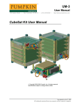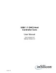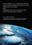
1
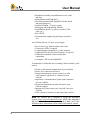
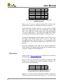
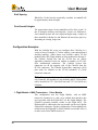
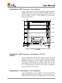
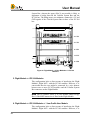
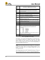
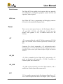
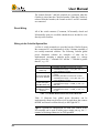
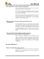
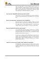
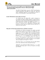
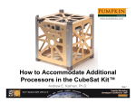
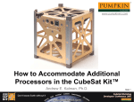
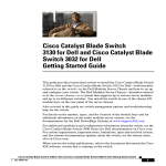
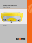
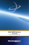
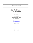
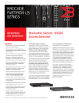
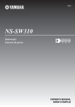
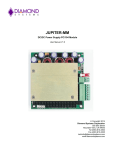
UM-3 User Manual 750 Naples Street • San Francisco, CA 94112 • (415) 584-6360 • http://www.pumpkininc.com Pumpkin CubeSat Kit User Manual Pumpkin CubeSat Kit1 REV D2 September 17, 2003 2000-2003 Pumpkin, Inc. and design MASSIF. All rights reserved. Specifications subject to change without notice. 1 Illustration depicts CubeSat Kit with MHX-2400 modem. Modem not included in CubeSat Kit. © Copyright 2003 Pumpkin, Inc. last updated on Sep 17, 2003 All trademarks mentioned herein are properties of their respective companies. User Manual Introduction Pumpkin, Inc.'s CubeSat Kit is an off-the shelf (OTS) kit designed to radically reduce the time and effort required to build a functional satellite conforming to the current CubeSat (http://cubesat.calpoly.edu/) specification. The CubeSat kit fully adheres to the CubeSat specification's electrical and mechanical requirements. The included Pumpkin CubeSat Flight Module sports an ultra-low-power single-chip microcontroller (<100mW) and a complete 80-pin system bus for expansion. The Flight MCU is pre-programmed with Pumpkin's Salvo Real-Time Operating System (RTOS) to facilitate rapid software development. A third-party spread-spectrum 2.4GHz transceiver module can be installed on the Flight Module without any modifications to the CubeSat Kit. In addition to the Flight Module, the 10x10x10cm CubeSat Kit can accommodate up to 4 (four) 8- or 16-bit PC/104-compliant modules, up to 5 (five) user modules,2 or a combination of both. Background The goal of the CubeSat project (http://cubesat.calpoly.edu/) is to deliver 1kg payloads in a 10cm cubed package into low earth orbit at low cost. Groups around the world are developing their own CubeSats. The CubeSat Kit evolved from a hardware and software co-design process. By combining a low-power, single-chip microcontroller with a weight-conscious mechanical design, the CubeSat Kit's available payload can be maximized. Design Partnership Pumpkin is partnering with design MASSIF to bring you the CubeSat Kit. 2 2 User modules in Slot 5 have additional height restrictions. UM-3 Pumpkin CubeSat Kit User Manual User Manual Figure 1: CubeSat Kit Partners Pumpkin has over 15 years experience in analog and digital hardware design and development, embedded programming and product design. Pumpkin will supply software, electronic hardware, documentation and web space for the project. design MASSIF has over 15 years of experience taking products from concept to market. design MASSIF's primary responsibility will be the mechanical design and packaging of the CubeSat kit. Both companies are actively involved in multiple projects in Silicon Valley. Motivation Both Pumpkin and design MASSIF are very excited to be involved in a space-related project, and are eager to see the CubeSat Kit deployed into space. Additionally, Pumpkin is eager to promote Salvo as the premier RTOS solution for embedded, single-chip microcontrollers. Figure 2: Salvo Tagline Salvo is a perfect fit for the CubeSat's microcontroller (i.e. its "brains"). Salvo fits in the smallest and lowest-power microcontrollers, thus keeping the electronics well within the tight mass and power constraints placed on each CubeSat. Also, programming a CubeSat in C with an RTOS should substantially shorten development times compared to other programming methodologies. The CubeSat Kit The CubeSat Kit contains: UM-3 Pumpkin CubeSat Kit User Manual 3 User Manual • Mechanical assembly (top and bottom covers, sides and feet) • Flight Module with Flight MCU • Development Board with Flight MCU header board and prototyping area • External benchtop +5V power supply • Debugging and programming interface • Miscellaneous parts (e.g. spacers, switches, USB cable, etc.) • Salvo RTOS • Documentation (engineering drawings, schematics, etc.) As a CubeSat Kit user, it's up to you to supply: • Power source (e.g. batteries and/or solar cells) • Custom user PCBs, if required • Communications equipment (e.g. radio, antenna) • Additional PCBs for your own electronics, if required • Additional mechanical, electrical and other components • A compiler / IDE for the Flight MCU To transform a CubeSat Kit into a working CubeSat satellite, you'll need to: • Decide on the internal configuration of your CubeSat • Solder a few connectors and wires • Design and implement a power system (e.g. solar cells, batteries, regulators, etc.) tailored to your CubeSat • Implement a communications system (radio, antenna) for your CubeSat • Design and implement any other electronics your CubeSat requires • Integrate all of these items (your "payload") into your CubeSat • Write software to interface to and control the CubeSat Note The CubeSat Kit is designed to accept the Microhard Systems (http://www.microhardcorp.com/) MHX-2400 Embedded Wireless Modem. This module operates in the 2.4000-2.4835 GHz ISM band. More information can be found at Microhard's website. 4 UM-3 Pumpkin CubeSat Kit User Manual User Manual Getting Started Development Board Flight MCU Unpack the following CubeSat Kit items: • Development Board • Flight MCU header board • Flight MCU programming / debug adapter • USB module • Benchtop +5V power supply3 • USB cable Verify that the jumpers on the Development Board are set to their default values for your Flight MCU: Jumper Setting JP1 JP2 JP3 JP4 JP5 JP6 JP7 JP8 JP9 JP10 JP11 JP12 JP13 JP14 OFF ON ON OFF ON OFF ON ON ON ON OFF OFF OFF 2-3 ! Table 1: Default Jumper Settings for Development Board for MSP430 Flight MCU Plug the Benchtop +5V power supply into J1 and verify the following voltages4: 3 4 Supplied without a power cord. Accepts IEC-standard power cords. There are several GND test points scattered across the Development Board. UM-3 Pumpkin CubeSat Kit User Manual 5 User Manual Signal Location Value +5V VCC VCC_MCU VCC_232 V+_232 V-_232 +5V_SW -RST/NMI TP9 TP12 TP20 TP21 TP19 TP22 TP10 TP8 +5V +3.3V +3.3V +3.3V > +5V < -5V 0V +3.3V ! Table 2: Startup Voltages for Development Board for MSP430 Flight MCU Remove the +5V power. Install the Flight MCU header board, being careful to observe its orientation (it only goes one way). If the Flight MCU header board has a socket, install the Flight MCU now. Again, observe the correct orientation of the Flight MCU in the Flight MCU header board socket. Plug the Benchtop +5V power supply into J1 – the LED on the Flight MCU header board should start blinking, indicating that it is running correctly. Connect the Programming / Debug Adapter to the JTAG port on the Flight MCU header board, and to your PC. Start your development software and verify that you can communicate with the Flight MCU. Verify that the manual reset switch (SW3) works properly. Successful verification of the tables above, and the Flight MCU header board's LED blinking indicate that the Development board is properly configured for the Flight MCU. USB Interface Follow FTDI's (http://www.ftdi.com/) instructions and install the FTDI USB drivers on your PC. Remove +5V power from the Development Board. Install the USB module in H7, observing the correct orientation. Reapply +5V power, and verify the following: Signal Location Value +5V_USB VCC_IO TP11 TP13 0V 0V ! Table 3: Voltages for Unpowered USB Module on Development Board for MSP430 Flight MCU Remove +5V power from the Development Board. Connect the USB cable between the USB module and your PC. Your PC should 6 UM-3 Pumpkin CubeSat Kit User Manual User Manual now recognize the USB device – follow the FTDI instructions on completing the driver installation. Verify the following: Signal Location Value +5V_USB VCC_IO -RST_USB TP11 TP13 H7.3 +5V +3.3V +3.3V ! Table 4: Voltages for Bus-powered USB Module on Development Board for MSP430 Flight MCU Open a terminal application (e.g. Windows Hyperterminal), connect to the USB ports emulated Com port (usually COM3 or COM4), and send a text file (any text file) to the Development Board. You should see the Rx LED light up to indicate the reception of serial data. Note You can send text through the USB port with the Development Board off because the USB-to-serial interface is buspowered, i.e. powered from the USB bus. Reapply +5V power to the Development Board. MHX Transceiver Remove +5V power from the Development Board. Install the MHX transceiver, observing the correct orientation. Attach an antenna to the transceiver. Reapply +5V power and restart the terminal program on your PC. From the terminal program, issue the command "T<CR>" to enable the MHX Transceiver and transmit a burst of data for 5 seconds. The TXMODE LED should light. The transmission ends automatically, and the TXMODE LED should extinguish. Additional Features The Development Board includes additional circuitry that is particularly useful when deriving power from other sources, and for measuring current draw. Refer to Circuit Description for more details. UM-3 Pumpkin CubeSat Kit User Manual 7 User Manual Configuring the CubeSat Kit User Modules User-provided Printed Circuit Board (PCB) modules must follow the PC/104 PCB layout in order to fit inside the CubeSat Kit and interface to the PC/104 bus, if desired. Additionally, these modules must locate the CubeSat System Bus connectors properly so as to be able to interface to the Flight Module. CubeSat Kit Slots The CubeSat Kit is designed to accept user or PC/104 modules in addition to the Flight Module. The locations of the modules are referred to as Slot 0 through Slot 5, where Slot 0 is at the Launch Switch end of the CubeSat. Modules are mounted in a stack of PCBs and connectors via threaded aluminum standoffs, PC/104style. The stack begins with the Flight Module in Slot 0 just inside the CubeSat Kit's top cover, and ends with the final slot's standoffs being attached to the CubeSat Kit body inside the bottom cover. The smallish dimensions of the CubeSat introduce certain limits on the modules when fitted in certain Slots. The constraints that deviate from the PC/104 specification are listed in Table 5, and are all mechanical in nature. 8 UM-3 Pumpkin CubeSat Kit User Manual User Manual Slot Accepts Height 0 Flight Module 15mm or 25mm 1 User module or PC/104 module 15mm 2 3 User module or PC/104 module User module or PC/104 module 4 User module or PC/104 module 5 User module (low-profile) Constraints on Module Only the Flight Module can be mounted in Slot 0. Cannot accept MHX transceiver if Slot 1 is occupied by a PC/104 module. User module must provide powered PC/104 connectors or include PC/104 stack-through connectors if PC/104 modules are used in Slots 2-5. Can be occupied by a PC/104 module if connectivity between user modules and the Flight Module is not required. When MHX transceiver is fitted on Flight Module, component keep-out area on underside of module must be observed. 15mm 15mm 13mm, 15mm or 23mm 6mm Greatly reduced topside component height. Only available when 15mm spacers are used between Slot 0 and Slot 1. Table 5: Slot Descriptions – Mechanical Compatibility Inter-Slot Spacing Since PC/104 connectors are used, the normal distance between adjacent modules is 15mm (0.6"), just like PC/104. However, there are a few special cases: Slot 0, Slot 4 and Slot 5. Slot 0 Spacing When an MHX transceiver is fitted to the Flight Module, 25mm (instead of 15mm) standoffs must be used between Slot 0 and Slot 1. Slot4 Spacing When Slot 4 is occupied by the last module, its standoff will be approximately either 13 or 23mm in length, dependent on the Slot 0 standoff length. If a module is fitted in Slot 5, Slot 4 will use the standard 15mm standoff. UM-3 Pumpkin CubeSat Kit User Manual 9 User Manual Slot5 Spacing When Slot 5 is the last slot occupied by a module, its standoff will be approximately 6mm in length. Final Standoff Heights The approximate nature of the standoffs used for Slots 4 and 5 is due to tolerance build-up and imperial / metric size differences. Users should measure the exact required height using a caliper on their assembled CubeSat kit, and fabricate the necessary spacer by shortening an existing, longer one. Configuration Examples With the CubeSat Kit, users can configure their CubeSats in a variety of ways. Examples 1-7 below employ a conventional board stacking topology, which places user modules and/or PC/104 modules above the Flight module in Slots numbered 0 through 5. The CubeSat System Bus and the PC/104 bus are (where applicable) connected from one module to another via PC/104style stackthrough connectors. The CubeSat System Bus connectors are on the opposite side of the CubeSat from the PC/104 connectors. The CubeSat System Bus connectors (2x20 pins each) are identical to the PC/104 standard's J2 (16-bit extension) connector. Note The examples below are for a "1U" CubeSat (10x10x10 cm). Naturally, the numbers of user modules and PC/104 modules can be increased in "2U" (10x10x20 cm) and "3U" (10x10x30 cm) CubeSats. 1. Flight Module + MHX Transceiver + 1 User Module This configuration uses the Flight Module, with an MHX transceiver mounted to it, and a user module that interfaces the user's payload with the Flight MCU on the Flight Module. The CubeSat's operating software resides in the Flight MCU. The Flight module is connected to the user module via the two CubeSat System Bus connectors. For this configuration, 25mm standoffs are used between the Flight MCU (Slot 0) and the user module (Slot 1) to make room for the MHX transceiver. 10 UM-3 Pumpkin CubeSat Kit User Manual User Manual 2. Flight Module + MHX Transceiver + 4 User Modules In this configuration, the CubeSat System Bus is extended through multiple user modules. To make room for the MHX transceiver, 25mm standoffs are used between the Flight Module in Slot 0 and the user module in Slot 1. 15mm standoffs are used between adjacent user modules. 12.9 SLOT#4 15.0 SLOT#3 15.0 SLOT#2 15.0 SLOT#1 MHX Modem 25.0 SLOT#0 4.5 Figure 3: Flight Module + MHX Transceiver + 4 User Modules 3. Flight Module + MHX Transceiver + User Module + 3 PC/104 Modules In this configuration, with the user module between the Flight Module and up to 2 PC/104 modules, the user module is likely to implement a bridge between the CubeSat System Bus and the PC/104 bus. The bridge must, at a minimum, connect the +5V and GND signals of the CubeSat System Bus to those of the PC/104 bus. A configuration like this may or may not have an additional processor on the PC/104 modules. 4. Flight Module + 2 User Modules + 2 PC/104 Modules In this configuration, two user modules are located between the Flight Module and the PC/104 modules. The lower (Slot 1) user module can interface solely to the Flight Module via the CubeSat UM-3 Pumpkin CubeSat Kit User Manual 11 User Manual System Bus, whereas the upper (Slot 2) user module is likely to implement a bridge between the CubeSat System Bus and the PC/104 bus. The bridge must, at a minimum, connect the +5V and GND signals of the CubeSat System Bus to those of the PC/104 bus. SLOT#4 SLOT#3 SLOT#2 SLOT#1 15.0 SLOT#0 Figure 4: Flight Module + 2 User Modules + 2 PC/104 Modules 5. Flight Module + 4 PC/104 Modules This configuration lacks a direct means of interfacing the Flight Module's Flight MCU with the PC/104 modules. However, it is conceivable that the two might be connected by a wire harness between one or more PC/104 modules and the CubeSat System Bus connectors on the Flight Module. Note Due to clearance issues, a PC/104 module cannot occupy Slot 1 if the MHX transceiver is fitted to the Flight Module. 6. Flight Module + 4 PC/104 Modules + 1 Low-Profile User Module This configuration lacks a direct means of interfacing the Flight Module's Flight MCU with the PC/104 modules. However, it is 12 UM-3 Pumpkin CubeSat Kit User Manual User Manual conceivable that the two might be connected by a wire harness between one or more PC/104 modules and the PCB pads for the CubeSat System Bus connectors. Note Due to clearance issues, a PC/104 module cannot occupy Slot 1 if the MHX transceiver is fitted to the Flight Module. 7. Flight Module + 4 User Modules + 1 Low-Profile User Module This configuration eschews the transceiver on the Flight MCU in favor of a user-supplied transceiver on one of the user modules. Choosing not to use the MHX transceiver reduces the spacing between Slot 0 and Slot 1 to only 15mm, and enables the fitting of an additional module in Slot 5. Note The user module in Slot 5 has additional constraints on its component height. Stackthrough-style connectors cannot be used on this module. 6.3 SLOT#5 SLOT#4 SLOT#3 SLOT#2 SLOT#1 15.0 SLOT#0 Figure 5: Flight Module + 4 User Modules + 1 LowProfile User Module UM-3 Pumpkin CubeSat Kit User Manual 13 User Manual 8. Non-stacking Topology An alternative board interconnect scheme seen in some CubeSats designs is to keep the various PCBs on the inside surfaces of the CubeSat, freeing the central volume for payload. This can also be achieved with the CubeSat kit. It requires that a user module interface to the Flight Module by plugging into the Flight Module at a right angle using alternate connectors.5 Overview of Examples Table 6 summarizes the configuration examples listed above. 5 14 This may require a custom, small intermediate PCB between the Flight Module and the user module in order to locate the user module against the CubeSat's inner skin. UM-3 Pumpkin CubeSat Kit User Manual User Manual # 1 2 3 4 5 6 7 8 Slots 0: Flight MCU 1: user module 2: payload 3: payload 4: payload 5: n/a 0: Flight MCU 1: user module 2: user module 3: user module 4: user module 5: n/a 0: Flight MCU 1: user module 2: PC/104 module 3: PC/104 module 4: PC/104 module 5: n/a 0: Flight MCU 1: user module 2: user module 3: PC/104 module 4: PC/104 module 5: n/a 0: Flight MCU 1: PC/104 module 2: PC/104 module 3: PC/104 module 4: PC/104 module 5: n/a 0: Flight MCU 1: PC/104 module 2: PC/104 module 3: PC/104 module 4: PC/104 module 5: user module (LP) 0: Flight MCU 1: user module 2: user module 3: user module 4: user module 5: user module (LP) 0: Flight MCU 1-5: n/a END: NST-N: NST-T: ST-N: MHX Xcvr OK? yes yes yes no no no yes yes Standoffs 0: 25mm 1: -2: -3: -4: -5: n/a 0: 25mm 1: 15mm 2: 15mm 3: 15mm 4: 13mm 5: n/a 0: 25mm 1: 15mm 2: 15mm 3: 15mm 4: 13mm 5: n/a 0: 15mm 1: 15mm 2: 15mm 3: 15mm 4: 23mm 5: n/a 0: 25mm 1: 15mm 2: 15mm 3: 15mm 4: 13mm 5: n/a 0: 15mm 1: 15mm 2: 15mm 3: 15mm 4: 15mm 5: 6mm 0: 15mm 1: 15mm 2: 15mm 3: 15mm 4: 15mm 5: 6mm 0: -1-5: n/a Connectors PC/104 CubeSat Bus System Bus 0: NST-T 1: ST-N 2: -3: -4: -5: -0: NST-T 1: ST-N 2: ST-N 3: ST-N 4: ST-N 5: -0: NST-T 1: ST-N 2: -3: -4: -5: -0: NST-T 1: ST-N 2: ST-N 3: -4: -5: -0: -1: -2: -3: -4: -5: -0: -1: -2: -3: -4: -5: -0: NST-N 1: ST-N 2: ST-N 3: ST-N 4: ST-N 5: END 0: user 1-5: n/a 0: -1: -2: -3: -4: -5: -0: -1: -2: -3: -4: -5: -0: -1: NST-N 2: ST-N 3: ST-N 4: ST-N 5: -0: -1: -2: ST-N 3: ST-N 4: ST-N 5: -0: NST-T 1: ST-N 2: ST-N 3: ST-N 4: ST-N 5: -0: NST-N 1: ST-N 2: ST-N 3: ST-N 4: ST-N 5: END 0: -1: -2: -3: -4: -5: -0: -1-5: n/a non-stackthrough, minimal protruding height above module's PCB surface (surface-mount recommended) non-stackthrough, normal height (for 15mm stacking) non-stackthrough, tall height (for 25mm stacking) stackthrough, normal height (for 15mm stacking) Table 6: Summary of Example CubeSat Kit Configurations The topology of the configuration you choose for your CubeSat Kit affects which connectors should be installed on the Development UM-3 Pumpkin CubeSat Kit User Manual 15 User Manual Board and Flight Module. Each CubeSat kit is supplied with a complete set of connectors for topologies that locate Slot 1 25mm above Slot 0. If your configuration requires Slot 1 to be only 15mm above Slot 0, or if you will be using a non-stacking topology, then you will need to source your own connectors instead of using the supplied ones. It is up to the user to solder the connectors onto the Development Board and Flight Module, and to any user modules. PC/104 modules are already supplied with the correct stackthrough connectors. 16 UM-3 Pumpkin CubeSat Kit User Manual User Manual Circuit Description Please refer to Schematic Diagrams while reviewing this section. Note The Development Board and Flight Module share the same circuitry. The Development Board has additional development and debugging features that are omitted from the Flight Module. The descriptions and reference designators below are for the Development Board. Overview All of the I/O pins, as well as some additional pins, of the Flight MCU microcontroller are connected to the CubeSat System Bus. Power (provided from elsewhere in the CubeSat) is regulated (if required) to meet the MCU's voltage requirements. Powerswitching and level-shifting are implemented as necessary. A reset supervisor is employed on the MCU's power bus. A bus-powered6 USB interface is provided, with isolation between it and the MCU. Provisions for a transceiver are also provided, again with isolation between it and the MCU. Voltage-level shifting and power switching are provided where necessary. Remove-Before-Flight and Launch switches are also provided. Flight MCU The Flight MCU (H6), a single-chip, ultra-low-power microcontroller with 48 I/O pins, is connected to the CubeSat System Bus connectors (H1, H2). A few of the MCU's I/O pins are dedicated or semi-dedicated to interfacing with and/or controlling other subsystems. 6 I.e. the USB system is powered by the +5V that is provided by the USB cable. UM-3 Pumpkin CubeSat Kit User Manual 17 User Manual Flight MCU Pin(s) P1[0..6] P1.7 P2[0..7] P3[0..3] P3.4 P3.5 P3.6 P3.7 P4[0..5] P4.6 P4.7 P5[0..7] P6[0..5] P6.6 P6.7 Availability on MSP430-based Designs Free to user. Dedicated to control of USB interface, i.e. normally a digital output. May be used as a digital input to sense whether VCC_IO is present. Free to user. Free to user. Free to user on Flight Module. On Development Board, can be connected to on-board RS-232 receiver. Free to user on Flight Module. On Development Board, can be connected to on-board RS-232 transmitter. Semi-dedicated as MCU transmit data to USB and transceiver interfaces. Can be used in any other way when neither USB nor transceiver interface is active. Semi-dedicated as MCU receive data from USB and transceiver interfaces. Can be used in any other way when neither USB nor transceiver interface is active. Free to user. Dedicated to controlling +5V_SW power. Free to user. Free to user. Semi-dedicated to USB and transceiver control interfaces. When either the USB or transceiver interface is active, these pins map to the following digital I/O functions (DTE/DCE where applicable): P6.0: -RTS/-CTS P6.1 -DTR/-DSR P6.2 -PWE/-DCD P6.3 -CTS/-RTS P6.4 -RI/-DTR P6.5 -RST/-RST When neither the USB nor the transceiver interface is active, then these pins are free for any purpose. Dedicated to control of transceiver interface. Free to user. Table 7: Flight MCU I/O Pin Usage From Table 7 we see that of the Flight MCU's 48 I/O pins, only 3 are permanently dedicated to on-board subsystems. The Flight MCU's UARTs can also interface with other off-board serial devices as long as those devices can be selected independently of the on-board USB and transceiver. Note On the Development Board, the Flight MCU is mounted on a separate PCB and connects to the Development Board via four headers. This allows the use of different Flight MCUs on the Development Board. Each Flight Module has its MCU soldered directly on it. There are dedicated Flight Modules for each type of supported Flight MCU. 18 UM-3 Pumpkin CubeSat Kit User Manual User Manual Clock Sources The Flight MCU has multiple clock options, which are normally user-configured by stuffing the appropriate crystals (X1-X4) and capacitors, where required. JTAG, etc. Each Flight MCU has a programming and debugging connector (J2) for use with standard development tools. Power There are two main power busses on the Development Board -+5V and VCC. VCC_IO, +5V_USB and +5V_SW are also present. GND (ground, i.e. 0V) is common across all of the circuitry. +5V +5V is connected directly to the PC/104 bus connectors (H3, H4) and is also available on the CubeSat System Bus connectors (H1, H2). Connector J1 is directly connected to +5V, and therefore can be used to supply +5V to the CubeSat from an external power source regardless of the status of the Remove-Before-Flight and Launch switches. +5V_SW +5V_SW is controlled by the Flight MCU, and provides +5V power on demand to the transceiver. +5V_SW is available on CubeSat System Bus connector H1. +5V_USB +5V_USB is derived directly from the USB connector, and is available on CubeSat System Bus connector H1. VCC VCC is normally generated on the Development Board from +5V via an ultra-low-quiescent-current low-dropout (LDO) regulator UM-3 Pumpkin CubeSat Kit User Manual 19 User Manual (U5). The LDO regulator's output is set to the desired VCC. VCC's value is chosen based on the Flight MCU. VCC is available on the CubeSat System Bus connector H2. The regulator's output can be disabled by taking OFF_VCC (available on CubeSat System Bus connector H1) high (i.e. to VCC). The nominal VCC voltage is +3.3V. VCC_IO This voltage is generated by the serial-to-USB converter and powers the interface between the Flight MCU and the serial-toUSB converter. VCC_IO is either _3.3V or +5V, depending on the Flight MCU. Note The USB specification stipulates that a maximum of 500mA be drawn by an USB device. GND A star-grounding scheme is used at the Flight MCU's analog and digital ground pins to minimize noise. Power-Switching +5V power to the transceiver is controlled by the Flight MCU via a P-channel MOSFET. Level-Shifting Logic-level voltage-shifting is employed via N-channel MOSFETs wherever signals generated on the VCC rail must control devices on the +5V rail. Reset An on-board Reset Supervisor (U4) is provided to externally reset (-RST/NMI) the Flight MCU should its power drop below a predetermined setpoint. An external reset signal (-RESET) is available on the CubeSat System Bus connector. An alternate Reset Supervisor (U9) can be fitted. 20 UM-3 Pumpkin CubeSat Kit User Manual User Manual USB A serial-to-USB 1.07 interface utilizing FTDI's FT232BM is provided. This interface is powered by the USB host to which it is connected (e.g. a laptop PC) and draws no power from the CubeSat. The MCU sees the serial-to-USB converter as Data Terminal Equipment (DTE). The serial-to-USB converter (H7) is isolated from the Flight MCU bus via the buffer U1. When the serial-to-USB converter is unpowered, U1 is in a high-impedance state. When the serial-toUSB converter is powered, VCC_IO powers U1. Normally, the Flight MCU's P1.7 (pulled high to VCC_IO) is configured as an input. To connect the Flight MCU to the serial-to-USB converter, the Flight MCU must drive P1.7 LOW while U1 is powered. Resistors R1-R4 are provided to avoid overcurrent damage if Flight MCU pins P3.7 and P6[0..2] are inadvertently configured as outputs when the interface is enabled. Resistors R5-R8are provided to avoid overcurrent damage if the FT232BM's TXD, -RTS and -RI pins are inadvertently configured as outputs when bit-bang mode is selected. The Flight MCU's interface to the USB subsystem is outlined in Table 8: Flight MCU Pin Associated USB Signal Name P1.7 -OE_USB P3.7 TXD_USB P3.6 RXD_USB P6.0 -RTS_USB P6.1 -DTR_USB P6.2 P6.3 P6.4 P6.5 -PWE_USB -CTS_USB -RI_USB -RST_USB Description Enables the USB interface when LOW (0V) AND the USB interface is active. USB Transmit Data, i.e. serial data from USB to Flight MCU. USB Receive Data, i.e. serial data from the Flight MCU to the USB. USB's Request-to-Send output. USB's Data Transmit Ready output. USB's -POWEREN output. USB's Clear-to-Send input. USB's Ring Indicator input. USB's Reset input. Polarity Active LOW Active HIGH Active HIGH Active LOW Active LOW Active LOW Active LOW Active LOW Active LOW Table 8: Flight MCU to USB Interface Signals 7 USB 2.0-compatible. UM-3 Pumpkin CubeSat Kit User Manual 21 User Manual Bit-Bang Mode The USB interface chip's bit-bang mode is supported. In this mode, data can be read and written as parallel data on the FT232BM's serial I/O pins, with the following restrictions: Serial I/O Pin Bit-Bang Pin TXD RXD -RTS -CTS -DTR -DSR -DCD -RI Data0 Data1 Data2 Data3 Data4 Data5 Data6 Data7 Bit-Bang Function(s) Supported Output only Input only Output only Input only Output only Not supported Not supported Input only Table 9: FT232BM Bit-Bang Mode Pin Functions The output-only and input-only restrictions arise because U1 is not a bidirectional device, and not all of the FT232BM's 8 bit-bang pins are connected through U1 to the MCU. MHX Transceiver An interface to accept an off-the-shelf 2.4GHz Spread-Spectrum transceiver is provided. This interface is powered by +5V and may draw substantial power from the CubeSat. The Flight MCU sees the transceiver as Data Communications Equipment (DCE). The transceiver (H5) is isolated from the Flight MCU bus via the buffers U2 and U3. When the Flight MCU wishes to transmit or receive, it enables the transceiver interface by taking P6.6 LOW. This powers up the transceiver, as well as U3. Resistors R9-R12 are provided to avoid overcurrent damage if Flight MCU pins P3.7 and P6[0..2] are inadvertently configured as outputs when the interface is enabled. The Flight MCU's interface to the transceiver subsystem is outlined in Table 10: 22 UM-3 Pumpkin CubeSat Kit User Manual User Manual Flight MCU Pin Associated Transceiver Signal Name P6.6 -OE_MHX P3.7 RXD_MHX P3.6 TXD_MHX P6.0 -CTS_MHX P6.1 -DSR_MHX P6.2 -DCD_MHX P6.3 -RTS_MHX P6.4 -DTR_MHX P6.5 -RST_MHX Description Enables the transceiver interface when LOW (0V). Transceiver Receive Data, i.e. serial data from transceiver to Flight MCU. Transceiver Transmit Data, i.e. serial data from the Flight MCU to the Transceiver. Transceiver Clear-to-Send output. Transceiver Data Set Ready output. Transceiver Data Carrier Detect output. Transceiver Request-to-Send input. Transceiver Data Terminal Ready input. Transceiver Reset input. Polarity Active LOW Active HIGH Active HIGH Active LOW Active LOW Active LOW Active LOW Active LOW Active LOW Table 10: Flight MCU to Transceiver Interface Signals External Control The transceiver can be controlled externally, i.e. by a processor other than the Flight MCU. This is done by applying +5V to the +5V_SW terminal on the CubeSat System Bus connector H1. Most of the transceiver's control signals are available on the CubeSat System Bus connector H1. Warning Simultaneous external control of the transceiver and Flight MCU enabling of the transceiver interface must be avoided! It is recommended that the interface and +5V_SW circuitry be removed if you intend to control the transceiver externally via the CubeSat System Bus connector H2. Remove-Before-Flight and Launch Switches Two separate, high-reliability switches are provided for the CubeSat's Remove-Before-Flight (RBF) and Launch switch specifications. Additionally, a dedicated pair of terminals (ZP1 & ZP2) are provided for a GND connection. The RBF Switch C and NO terminals are connected when the CubeSat's RBF pin is in place. When the RBF pin is removed, the RBF switch C and NC terminals are connected. UM-3 Pumpkin CubeSat Kit User Manual 23 User Manual The Launch Switch C and NO terminals are connected when the CubeSat is placed into the CubeSat launcher. When the CubeSat is released from the launcher, the Launch switch C and NC terminals are connected. Direct Wiring All of the switch contacts (C/common, NC/normally closed and NO/normally open) are available should the user decided to wire directly to the switches. Wiring via the CubeSat System Bus 4 of the 6 switch terminals are provided on the CubeSat System Bus connector H2, and implement 4 of the 5 distinct terminals of two serially-connected switches. The following CubeSat global power disconnect schemes are examples of what can be implemented, assuming a unipolar power supply (i.e. voltage source) where the "-" terminal is 0V and the "+" terminal is greater than 0V, e.g. +5V. Description Ground-Lift with RBF Switch only Ground-Lift with RBF and Launch Switches Power Interruption with RBF Switch only Power Interruption with RBF and Launch Switches Implementation • CubeSat System Bus Connector H2: Connect CubeSat power supply "-" to LS_NC, and "+" to power distribution circuitry. • Flight Module / Development Board: Connect ZP1 to ZP2 • CubeSat System Bus Connector H2: Connect CubeSat power supply "-" to LS_NC, and "+" to power distribution circuitry. • CubeSat System Bus Connector H2: Connect CubeSat power supply "-" to RBF_C, and "+" to RBF_NC. • CubeSat System Bus Connector H2: Connect CubeSat power supply "-" to RBF_C, and "+" to LS_NC. Table 11: CubeSat Global Power Disconnect Schemes Table 11 illustrates how global power disconnect can be implemented without any discrete wires beyond those that connect the RBF and Launch switches directly to the Flight MCU. Tip In a ground-lift configuration, the RBF and Launch switch NO terminals can be used to hold a power supply pin (e.g. the "+" terminal of discharged batteries) at GND potential. 24 UM-3 Pumpkin CubeSat Kit User Manual User Manual CubeSat System Bus The CubeSat System Bus (on connectors H1 and H2) provide a means of connecting the Flight MCU's 48 I/O pins, and additional Flight MCU pins, to user circuitry elsewhere in the CubeSat. The CubeSat System Bus connector pinout is outlined below: Pin(s) Signal Name Type Logic Level 1-8 9-16 17-24 P5[7..0] P4[7..0] P3[7..0] I/O I/O I/O VCC VCC VCC 25 XT2IN clock VCC 26 VREF+ O VCC 27 XT2OUT clock VCC 28 VEREF+ I VCC 29 -RESET I VCC 30 VREF- I VCC 31 OFF_VCC I VCC 32 +5V_USB PWR 33 +5V_SW PWR 34 35 36 37 -RST_MHX -CTS_MHX -RTS_MHX -DSR_MHX I O I O +5V_SW +5V_SW +5V_SW +5V_SW 38 -DTR_MHX I +5V_SW 39 40 -TXD_MHX -RXD_MHX I O +5V_SW +5V_SW Description Flight MCU Port P5 Flight MCU Port P4 Flight MCU Port P3 Flight MCU external crystal / clock Flight MCU internal A/D reference Flight MCU external crystal / clock Flight MCU external + reference External –RESET to Reset Supervisor Flight MCU external reference External disable of on-board VCC regulator From USB Interface. Must not exceed 500mA. Normally from +5V, under Flight MCU control Transceiver Reset Transceiver Clear-to-Send Transceiver Request-to-Send Transceiver Data Set Ready Transceiver Data Terminal Ready Transceiver Transmit Data Transceiver Receive Data Table 12: CubeSat System Bus Connector H1 Pin(s) Signal Name Type 1-8 9-16 17-24 25,26 27,28 29-32 P6[7..0] P1[7..0] P2[7..0] +5V VCC GND I/O I/O I/O PWR PWR PWR 33, 34 LS_NC I/O 35,36 LS_NO I/O 37,38 RBF_NC I/O 39.40 RBF_C I/O Logic Level VCC VCC VCC Description Flight MCU Port P6 Flight MCU Port P1 Flight MCU Port P2 PC/104 Bus +5V Flight Module power System GND Launch Switch Normally Closed Terminal Launch Switch Normally Open Terminal Remove-Before-Flight Switch Normally Closed Terminal Remove-Before-Flight Switch Common Terminal Table 13: CubeSat System Bus Connector H2 UM-3 Pumpkin CubeSat Kit User Manual 25 User Manual PC/104 Bus As detailed in PC/104 Compatibility, only +5V and GND are available to from the PC/104 bus. Therefore only a 32-pin subset of the total of 104 PC/104 connector pins are implemented. Additional Components and Circuitry Bypass Capacitors Bypass capacitors across each power supply are provided. Test Points Test points for signals of interest are provided. Additional Features of the Development Board Power The Development Board accepts 6-24V dc input as a source for system power via an additional LDO regulator with fixed +5V output. 6-24V dc can be applied via a 2.1 or 2.5mm dc power plug (center is + polarity), or via laboratory banana jacks (GND/- is black, + is red). Each major power connection can be interrupted by means of a jumper. This allows the user to isolate any part of the power system from another, which is especially useful when measuring currents. Reset A manual Flight MCU Reset pushbutton switch is provided. Indicators LED indicators are provided for +5V, VCC, USB Rx/Tx status and transceiver status. 26 UM-3 Pumpkin CubeSat Kit User Manual User Manual USB The Development Board uses a replaceable USB module. RS-232 A micro-power RS-232 transceiver (configured as DTE, for software (XON/XOFF) handshaking) is provided. It can be selectively enabled or disabled. Prototyping Area The Development Board includes a 26x30 0.100" grid for use as a prototyping area. Additionally, two 1x30 0.100" columns of GND and two 1x15 / 1x15 0.100" columns of +5V / VCC power are provided. UM-3 Pumpkin CubeSat Kit User Manual 27 User Manual PC/104 Compatibility The PC/104 standard provides electrical and mechanical specifications for embedded systems using the PC and PC/AT (ISA) bus standard in a custom form factor. PC/104 cards are popular in industrial control and monitoring, and provide an OTS means of obtaining considerable computing and I/O power in a compact form factor. Mechanical Compatibility The CubeSat Kit is designed to accept stackthrough PC/104 cards above the Flight Module. The restrictions on the card slots are listed in Table 5. 25mm (1") M3 threaded spacers are normally used between adjacent slots. If a transceiver is not fitted on the Flight Module (Slot 0), 15mm spacers8 should be used between Slot 0 and Slot 1. This configuration leaves room for a low-profile user module in Slot 1, but not enough for a PC/104 module in that slot. Connectors The PC/104 connectors on the Flight Module are of the nonstacking type. They are either 15mm or 25mm tall, depending on whether a transceiver is fitted to the Flight Module. All other PC/104 connectors are of the conventional, stackthrough type. Note Only J1 pins 1-4 and 29-32, and J2 pins 0-3 and 16-19 are implemented on the Flight Module. Therefore, to connect J1 or J2 to a PC/104 module in Slot 1, 2x4 headers (instead of 2x32 and 2x20, respectively) are used. Voltages Warning The MSP430 on the Flight Module is a +3.3V only MCU. Therefore level-shifting circuitry must be used when interfacing this MCU to the PC/104 bus, which runs at a nominal 8 28 And taller PC/104 bus connectors. UM-3 Pumpkin CubeSat Kit User Manual User Manual +5V. Connecting +5V to any pin on the MSP430 will irreparably damage the device! Texas Instruments and other manufacturers have logic families specifically designed to translate +3.3V to +5V, sometimes bidirectionally. Electrical Compatibility The ISA bus specification, around which PC/104 is built, is designed fundamentally for microprocessors, not microcontrollers (MCUs). I.e. it is designed for use with processors that have external data and address busses, and the associated control signals. The ISA bus is not well-suited for use with microcontrollers. Interfacing a single-chip microcontroller to the ISA bus usually involves a considerable amount of "glue" logic. Additionally, the speeds9 of processors on the ISA bus often greatly exceed those of popular microcontrollers, further complicating the interface. Interfacing to PC/104 For the reasons above, the CubeSat Kit's Flight Module makes no attempt to interface to the PC/104 bus, save for +5V and GND. We recommend that interfacing the Flight MCU to the PC/104 bus be done on the user module in Slot 1. Since all of the Flight Module's I/O pins are available on the CubeSat Bus Connectors, any interface between the PC/104 bus and the Flight MCU can be implemented. For example, if you wanted to implement an 8-bit data port with handshaking between the PC/104 bus and the Flight MCU, you would probably use one of the Flight MCU's 8-bit I/O ports, along with a few dedicated handshaking lines. This circuitry would reside on the Slot 1 User Module, which connects to the Flight Module in Slot 0 via the CubeSat Bus connector, and to the PC/104 bus of Slots 2-4 via the PC/104 bus connectors. PC/104-Plus Compatibility The CubeSat Kit does not directly support the PC/104-Plus (32-bit) standard. However, PC/104-Plus modules can be mounted in any 9 E.g. a 50MHz 486-class processor. UM-3 Pumpkin CubeSat Kit User Manual 29 User Manual slot that normally accepts PC/104 modules, as long as there is no mechanical interference between the PC/104-Plus module's 32-bit connectors and the rest of the system. 30 UM-3 Pumpkin CubeSat Kit User Manual User Manual Frequently Asked Questions (FAQ) General What is the CubeSat Kit designed to do? The CubeSat Kit is designed for low mass, high strength, maximum useable surface area, minimum power consumption and maximum configurability while conforming to the CubeSat specifications. What do I have to add to the CubeSat Kit to turn it into a functional satellite that's ready for launch? At a minimum, you'll need to add a power source (i.e. batteries, solar cells, etc.), and your payload / experiment. You'll want to add a transceiver and an antenna if you plan to communicate with your CubeSat. Plus, you'll need to program the Flight MCU to run your CubeSat and handle communications, etc. Why doesn’t the CubeSat kit include an antenna / solar cells / …? The design of items like antennas and power-supplies is very mission-oriented, and should be tailored to each individual CubeSat. The CubeSat Kit is a general-purpose kit, and is designed to satisfy the basic requirements of the CubeSat specifications. With the CubeSat Kit, you don’t have to worry about building a sturdy yet light enclosure, adding Remove-Before-Flight and Launch Switches, creating a working connector scheme, picking a microcontroller, etc. We've done all of that for you! Does the CubeSat Kit include a radio (transceiver)? No, but you can buy one from Microhard Systems (http://www.microhardcorp.com/) off-the shelf, plug it into the Flight Module, add an antenna and you're ready to begin sending and receiving. UM-3 Pumpkin CubeSat Kit User Manual 31 User Manual I prefer to use / design my own radio. Will that work in the CubeSat Kit? Yes. The CubeSat Kit can be configured in various ways. You can put your own radio in the CubeSat Kit. Do I have to create my own Printed Circuit Boards (PCBs) in order to use this CubeSat Kit? No. For simple designs, you can use the Flight Module's powerful MCU as your primary controller. You can put your own electronics (serial EEPROMs, sensors, power supply, connectors, etc.) on any PC/104 prototyping cards (available from various manufacturers) and connect them via the CubeSat System Bus connectors. Sophisticated users with complex designs will want to build their own modules on custom PCBs. Again, these will connect to the Flight MCU via the CubeSat System Bus connectors. User modules can also connect to the PC/104 bus, or even the PC/104Plus bus. Why is the PCB mounting scheme of the CubeSat Kit designed around the PC/104 mechanical specifications? First, the PC/104 specification has a simple, pass-through connector scheme that is well-suited to the tight confines of the CubeSat. The CubeSat System Bus connector is the same as the standard PC/104 stackthrough 40-pin connector, a well-established industry standard. Second, many potential CubeSat developers want to run sophisticated applications on their CubeSats that they can first develop on PCs. By accommodating +5V-only PC/104 modules, the CubeSat Kit supports x86-class single-board computers (SBCs) in the PC/104 form factor like the Diamond Systems (http://www.diamondsystems.com/) Prometheus SBC, which was used in the successful QuakeSat project (http://www.quakefinder.com/quakesat.htm). Naturally, other PC/104 modules can also be used in the CubeSat Kit. Third, the mechanical layout of PC/104 modules leaves a considerable percentage of the total PCB area available for circuitry. 32 UM-3 Pumpkin CubeSat Kit User Manual User Manual What equipment do I need to program the Flight MCU? All you need beyond the CubeSat kit is a PC and a compiler / Integrated Development Environment (IDE). The CubeSat Kit contains all of the hardware required to connect a PC to the Development Board and Flight MCUs for downloading, programming and debugging. Each CubeSat Kit also includes the Salvo RTOS for the MCU on the Development Board and Flight Module. You will need a compiler to develop software for this MCU. Low-cost compilers and IDEs are commercially available. What's the difference between the Development Board and the Flight Module? The Development Board is on a much larger PCB to facilitate access to the various systems on-board. It also includes provisions for multiple power supply sources, and jumpers to isolate parts on the system. It also includes some additional circuitry not available on the Flight Module (e.g. indicator LEDs and an RS-232 port). Electrically, the Flight Module is a subset of the Development Board. Why aren't the PC/104 and CubeSat System Bus connectors soldered to the Development Board and Flight Module? There are three basic configurations for the CubeSat kit, each of which uses different connectors. The kits are supplied with the connectors for the most common configuration as separate parts. By doing this, you won’t have to unsolder the connectors and risk damaging the boards if you need one of the alternate configurations. Assembly / Mechanical What is the CubeSat Kit structure made of? The CubeSat Kit is made from sheet aluminum, in thicknesses appropriate for each individual part. All external fasteners are made from stainless steel. UM-3 Pumpkin CubeSat Kit User Manual 33 User Manual Is the CubeSat Kit an inch or metric design? All of the user-serviceable fasteners are metric. All relevant dimensions are presented in metric units. Is the CubeSat Kit structure hard-anodized? Yes, to prevent galling when in contact with the CubeSat launcher. Why is there an oval cutout on the front face of the CubeSat Kit? This cutout enables the MHX transceiver to fit within the confines of the CubeSat's 10x10x10 cm size. If you use the MHX transceiver, you'll find that this cutout leaves enough room to attach your antenna cable to the MHX transceiver. If you don’t use the MHX transceiver, you can put solar cells over the cutout, run other wires in and out of the CubeSat there, etc. It doesn’t look like I can fit all of my payload into a 10x10x10cm CubeSat Kit. Are larger CubeSat Kits available? Yes, 10x10x20cm and 10x10x30cm CubeSat Kits are available. They are identical to the 10x10x10cm CubeSat Kit except for their chassis, which are correspondingly longer. Environment What temperature range is the CubeSat Kit designed for? All of the parts in the CubeSat kit that are destined for space operate over the –40 to +85 C industrial temperature range. What kinds of glues and/or epoxies are used in the CubeSat Kit? All of the components in the CubeSat Kit are permanently riveted, positively fastened with machine screws, or soldered to the Flight Module. Some space-grade adhesives are used to lock certain fasteners in place. What kind of wiring does the CubeSat Kit have? The only wires in the CubeSat Kit connect the Remove-BeforeFlight and Launch switches to the Flight Module or to user 34 UM-3 Pumpkin CubeSat Kit User Manual User Manual circuitry. All other inter-board interconnects are done with 0.100" spacing headers. Payload My CubeSat payload is very flat. Can I put it on a PC/104 card? Sure. If you design your payload to fit inside a PC/104 module's form factor, you can stack it along with the other user modules and PC/104 modules in your CubeSat. My CubeSat payload measures 5x5x5cm. Can the CubeSat Kit accommodate it? Yes. With only the Flight MCU in place, there's plenty of room for large payloads. You may want to consider mounting any user modules against the side walls of the CubeSat Kit. How can I run wires from a module to the top surface of the CubeSat Kit (the one where the Flight Module is mounted)? There is a 4.7mm slot between the front edge of the Flight Module and the CubeSat inner wall. To reach that surface from inside the CubeSat (e.g. to wire solar cells), route your wires through that slot. The allowable height on Slot 5 is only 6mm. What is Slot 5 good for? Slot 5 is immediately below the CubeSat Kit's bottom cover. Therefore it's an ideal location to place sensors that must be exposed to space, e.g. a miniature camera lens. Just cut a hole in the bottom cover that's large enough for the camera lens to pass through, and not violate the CubeSat's allowable external dimensions. UM-3 Pumpkin CubeSat Kit User Manual 35 User Manual Electronics How much power does the Flight MCU take? The Flight MCU uses an ultra-low-power microcontroller. At full speed,10 the entire Flight Module should consume no more than 20mA @ +3.3V (66mW). By taking advantage of the MSP430's power-saving design and the event-driven Salvo RTOS, the average current should drop to well below 1mA (3.3mW). Why is a linear regulator used to generate VCC? I thought switchers are more efficient. A low-dropout (LDO) linear regulator was chosen for this application primarily because it requires fewer parts (thus enhancing reliability and reducing weight) than most switchers, and the Flight MCU's power consumption is so low that the overall system power savings would be negligible with a switcher. If your CubeSat already generates a suitable VCC, you should remove the regulator on the Flight Module and feed it VCC via the CubeSat System Bus connector. What kinds of electronic components are used in the CubeSat Kit? Primarily small surface-mount components, like 0805 and 1206 passive packages, and TQFP chip packages. With some skill and experience, they can be reliably soldered by hand. How much current can the Remove-Before-Flight and Launch Switches conduct? They are each rated for 10A. The same switches are used in the 10x10x10cm, 10x10x20cm and 10x10x30cm CubeSat Kits. Why are separate signals from the Flight MCU used to enable +5V_SW power and the MHX transceiver interface? This is done primarily for two reasons: 1) The MHX transceiver takes a relatively long time to power up. The –ON_+5V signal 10 36 8MHz for an MSP430-based Flight Module, does not include power required by the transceiver. UM-3 Pumpkin CubeSat Kit User Manual User Manual allows the Flight MCU to keep the MHX transceiver power on while the interface is disabled and the I/O pins are used for other purposes. 2) For CubeSat Kit configurations that employ the Flight MCU as the main processor, +5V_SW can be used as a power supply signal that is under the Flight MCU's control. Can I leave the Flight MCU on all the time while in orbit? Theoretically, yes. Its power consumption is so small (especially in its power-saving modes) that you can probably leave it on all the time. How do I manage power consumption in the CubeSat Kit? The biggest drain on your power supplies is likely to be your transceiver (radio), especially when transmitting. The Flight MCU can control power to the MHX transceiver, so that it only consumes power when the Flight MCU is ready to transmit data. Does the CubeSat Kit include a power supply? A 5V external table-top power supply is included for use with the Development Board and the Flight Module. It is used to power the Development Board, and can also power an assembled CubeSat through the external power connector. It is up to you to design your own internal power system for your CubeSat. This will normally involve solar cells and/or batteries, and may require outputs at multiple voltages (e.g. +3.3V and +5V). CubeSat power supplies are normally tailored to the CubeSat's payload and processor(s). I want to run Linux in my CubeSat. Is the CubeSat Kit compatible? The Flight MCU is much too small to run Linux. However, there are many off-the-shelf PC/104 modules with processors that are capable of running Linux. So, just pick one and put it in your CubeSat Kit. UM-3 Pumpkin CubeSat Kit User Manual 37 User Manual I plan on running both a PC/104 SBC and the Flight Module's MCU in a dual-processor configuration. How can I interrupt the Flight MCU from the SBC? The MSP430 Flight Module accepts the –RESET signal from the CubeSat System Bus. This signal can activate the –RST/NMI signal. The MSP430 Flight MCU can be configured in software to treat the –RST/NMI signal as a non-maskable interrupt. Are the '244 interface chips really necessary? Yes. Without them, the Flight MCU could be subjected to overvoltages on its inputs, leading to damage. The type of interface chips and the overall circuit topology has been carefully chosen to eliminate any chance of damage to the Flight MCU from the +5Vbased USB-to-serial converter and MHX transceiver in any powered or unpowered state. Additionally, the interface chips guarantee the correct logic-level signals when the Flight MCU is connected to either interface. Why does the Development Board have an RS-232 connector? To facilitate your CubeSat development. For example, you might decide that the easiest way to interface the Flight MCU to a PC/104 or PC/104-Plus module with an x86-class processor running Linux is via a serial port. This is advantageous, because RS-232 drivers operate at RS-232 voltage levels, which bypasses the issue of +3.3V to +5V translation. So, You could place your PC/104 module on the Development Board and connect its processor to the Flight MCU via this serial port. You would need to eventually design your own RS-232 interface on a user module when you integrate your design into a CubeSat. The RS-232 driver is not incorporated into the Flight Module because that would unnecessarily constrain the design. Alternatively, you could use the RS-232 port for printf()-style debugging, and simply ignore it when you integrate your design into a CubeSat. 38 UM-3 Pumpkin CubeSat Kit User Manual User Manual Communications Interfaces (USB and MHX Transceiver) How can I use the Flight MCU's A/D inputs to sample voltages throughout my CubeSat? They're connected to the USB and MHX transceiver interfaces! You can use most of the Flight MCU's analog inputs for voltage sampling because the USB-to-serial converter and the MHX transceiver are normally isolated from the Flight MCU's bus. When you want to sample, disable the interfaces, configure the I/O pins as analog inputs, and sample. When you want to connect to either the USB-to-serial converter or the MHX transceiver, configure the I/O pins as digital inputs or outputs, and enable one of the interfaces. The I/O pins that enable the interfaces must always be configured as digital inputs or outputs. A few precautions must be taken for this to work properly. You can either selectively isolate your analog sources from the Flight MCU bus (e.g. by using an analog switch), or you can buffer the analog sources in a manner that's tolerant of being driven by a digital signal appearing at the I/O pin. Can I use the Flight MCU's second UART to talk to serial devices other than the USB-to-Serial converter and MHX transceiver? Yes. When neither of these on-board interfaces is enabled, you can talk to other serial devices. You must ensure that when either the USB-to-serial converter or the MHX transceiver is enabled, your other serial devices are disabled (tri-state / hi-Z) on the UART's receive data pin. Can the Flight MCU talk to both the USB-to-serial converter and the MHX transceiver at the same time? No. Only one interface should be active at the same time. Control of the interfaces is under the Flight MCU's control. The USB-toserial converter is envisioned as an "on the ground" communications link, and the MHX transceiver is envisioned as an "in-flight" communications link. Therefore you would not normally need to have both active at any time. UM-3 Pumpkin CubeSat Kit User Manual 39 User Manual Why don’t the data and control signal names for the two interfaces match? They don’t match because one is Data Terminal Equipment (DTE), and the other is Data Communications Equipment (DCE). What kind of handshaking do the interfaces support? The USB-to-serial converter interface supports simple hardware handshaking (RTS/CTS), as well as software handshaking (XON/XOFF). The MHX transceiver supports full hardware handshaking (RTS/CTS, DSR/DTR, DCD), as well as software handshaking. Can I reset the interfaces? Yes. Each interface can be reset by the Flight MCU. Can an external processor interface with the USB-to-serial converter? No. To move data from an external processor (e.g. a PC/104 SBC) through the USB-to-serial converter will require that the external processor communicate with the Flight MCU serving as an intermediary. Can an external processor interface with the MHX transceiver? Yes, directly over the CubeSat System Bus. This requires that the external processor apply +5V power to +5V_SW. All of the MHX transceiver's data and control signals except DCD are available on the CubeSat System Bus connectors. Can I use the USB port in space? If your USB cable is long enough … The USB chip uses almost as much power as the Flight MCU! Isn't that wasteful? The USB interface is designed so that it is only powered when connected to an external host (e.g. a laptop PC). At all other times the USB interface consumes no power. 40 UM-3 Pumpkin CubeSat Kit User Manual User Manual Why aren't any MHX transceiver status indicators available to the Flight MCU or on the CubeSat System Bus connector? All of the MHX transceiver's status information can be gleaned by reading from its internal registers. Therefore these signals are unnecessary. They are attached to LEDs on the Development Board as a visual aid. I prefer to use my own radio. How can I integrate it into the CubeSat Kit? The simplest approach is probably to package your radio in the same form as the MHX transceiver, so that it can be plugged into the MHX transceiver sockets. You can then choose to control the radio from the Flight MCU, or externally via the CubeSat System Bus. Note that the MHX transceiver socket is supplied with +5V power from +5V_SW. Can I use the USB-to-serial converter's serial memory chip for purposes other than USB configuration? No, it is not intended for general-purpose use. Shouldn't I be concerned with the MHX transceiver's cable sticking out of the side of the CubeSat Kit? Not really. The MHX transceiver is quite large compared to the CubeSat, and we felt that this was the best installation location for it. The cable is still within the CubeSat specifications regarding items protruding above the CubeSat sides. We recommend you use some mechanical means to ensure that the cable will stay connected to the transceiver. The fact that it is exposed to space is not cause for worry. PC/104 How PC/104-compatible is the CubeSat Kit? PC/104 boards that do not extend beyond the primary board dimensions of 90x96mm can be mounted inside the CubeSat. Power (+5V) and ground connections to the Flight Module are provided in the J1 and J2 connectors. UM-3 Pumpkin CubeSat Kit User Manual 41 User Manual Why are only a few of the PC104 bus pins implemented on the Flight Module? Because the PC/104 bus is designed for microprocessors and not microcontrollers (like the Flight MCU), it is not easily interfaced to a microcontroller. Therefore, only +5V power and GND are connected from the Flight Module to the PC/104 bus. When are PC/104 connectors required on the Flight Module? The 2x4 PC/104 connectors are only required on the Flight Module when there is a PC/104 module in Slot 1, or when there are PC/104 modules in Slot 2 through Slot 4 and you haven't connected the +5V and GND signals on the CubeSat System Bus connectors to the PC/104 connectors in a user "bridge" module. How many PC/104 cards can I fit in the CubeSat Kit? You can fit a total of 4 PC/104 cards in the 10x10x10cm CubeSat Kit. They mount directly above the Flight Module. Can I use a PC/104 prototyping card to build a user module? Yes. The Diamond Systems (http://www.diamondsystems.com/) Proto-104 prototyping card can be used. PC/104 and/or CubeSat System Bus connectors can be soldered to it to mate with a Flight Module. Can I use off-the-shelf PC/104 modules in the CubeSat Kit? Yes. Any PC/104 module can be used. If it's a +5V-only module, it will plug right into the module stack. If it requires other voltages, you'll have to provide them, too. Can I use PC/104-Plus modules in the CubeSat Kit? Yes. Any PC/104-Plus module can be used.11 The Flight Module only has +5V and GND for 8- or 16-bit PC/104 cards. If your PC/104-Plus module requires other voltages, you'll have to provide them, too. 11 42 Physical packaging issues dictate that a user module can connect to the PC/104 bus, and to either the PC/104-Plus bus or the CubeSat System Bus, but not both. UM-3 Pumpkin CubeSat Kit User Manual User Manual I plan to use a PC/104 SBC running Linux in my CubeSat, and I'm not sure I want / need the Flight Module. Can I remove it to save weight? The Flight module performs several functions in addition to being the home of the Flight MCU. The Remove-Before Flight switch and MHX transceiver are mounted to it. Additionally, there is not enough room to mount a PC/104-sized module in Slot 0. Therefore you should probably keep the Flight Module, and consider assigning it another role (perhaps that of a system supervisor or backup processor) outside of the functionality you plan to implement on your Linux SBC. Why can't I use the MHX transceiver with a PC/104 module in Slot 1? There isn't enough room. The PC/104-Plus specification calls for approximately 5mm of clearance below any PC/104-Plus card. PC/104 Cards often have components on the underside of the PCB, too. With the MHX transceiver on the Flight Module, there simply isn't enough room to accommodate components on the underside of the module in Slot 1. To use the MHX transceiver with PC/104 cards, you could design your own user module for Slot 1, and place your PC/104 module in Slot 2 or higher. Or, you could design your own transceiver to plug into the Flight Module – it would require a substantially lower profile than the MHX transceiver. Software What programming background does the CubeSat Kit require? You should be comfortable programming microcontrollers in C. Some experience with programming paradigms beyond the simple foreground / background loop is helpful. What kind of software does the CubeSat Kit include? The Flight MCU comes pre-programmed with a basic "skeleton" application that will get you started. It's based on the Salvo RTOS, to make it easier for users to manage the multitude of things the Flight MCU will be called upon to do. All application source code (in C) is included. UM-3 Pumpkin CubeSat Kit User Manual 43 User Manual What are the advantages of this RTOS-based software approach? RTOS-based programming is one of the dominant programming paradigms for embedded programming. The Internet is full of information on this subject. Because Pumpkin's (http://www.pumpkininc.com/) Salvo RTOS is an event-driven RTOS, you will be able to minimize power consumption while maximizing functionality in the Flight MCU. How do I interface to the USB port? You'll need FTDI's (http://www.ftdi.com/) drivers to interface your PC to the CubeSat Kit's USB port. You can use the USB port as a simple terminal interface to the Flight MCU, or you can write your own software in the Flight MCU and/or the host side to do things like serial bootloaders, etc. 44 UM-3 Pumpkin CubeSat Kit User Manual User Manual Discussion Forums A series of CubeSat User Forums have been created on the Pumpkin web site for the express purpose of discussing issues that surround the CubeSat kit. Announcements, notices, links to relevant files, etc. will all be posted to the Forums. To access the forums, choose the Forums link from Pumpkin's home page. New users must register before they are allowed to post new topics or reply to existing ones. Note We would like all discussions regarding the CubeSat kit to take place in the Forums, not via private email. UM-3 Pumpkin CubeSat Kit User Manual 45 User Manual Printed Circuit Board Layouts Development Board Figure 16: Layer 1 and Silkscreen (Do Not Scale) 56 UM-3 Pumpkin CubeSat Kit User Manual User Manual Part Numbers Pumpkin Part Number Description 703-00243 703-00244 703-00245 703-00246 703-00247 703-00248 703-00249 703-00250 705-00193 705-00194 711-00227 711-00241 711-00242 Body – 1U Body – 2U Body – 3U Top Cover Bottom Cover Foot – Top, Helper Spring Foot - Top Foot - Bottom MSP430 Flight Module Development Board Kit – 1U Kit – 2U Kit – 3U Notes 10cm tall 20cm tall 30cm tall for MSP430F149 general-purpose for 10x10x10cm CubeSats for 10x10x20cm CubeSats for 10x10x30cm CubeSats Table 14: Pumpkin CubeSat Kit Major Part Numbers UM-3 Pumpkin CubeSat Kit User Manual 57 User Manual Contact Information Pumpkin Contact design MASSIF Contact Pumpkin Web Site design MASSIF Web Site Digi-Key Corporation 58 Andrew Kalman [email protected] (415) 584-6360 Adam Reif [email protected] (530) 620-6402 http://www.pumpkininc.com/ http://www.designmassif.com/biz/ http://www.digi-key.com/ UM-3 Pumpkin CubeSat Kit User Manual