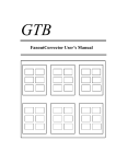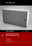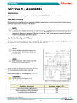
1
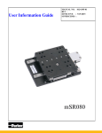
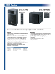
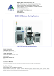
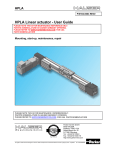
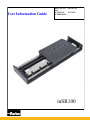
User Information Guide
MANUAL NO. 102-6307-01
REV EFFECTIVE : 5/15/2015
SUPERCEDES :
mSR100
User Information Guide
For assistance contact:
Parker Hannifin Corporation
Electro Mechanical Division
1140 Sandy Hill Road
Irwin , PA 15642
Ph 724-861-8200
800-245-6903
E-mail : [email protected]
www.parkermotion.com
2
WWW.PARKERMOTION.COM
PH: (724)-861-8200
User Information Guide
MSR Series Product Manual
Introduction………………………………….………………………………………………………….5
General Information…………………………………………………………………….…5
Return….………………………………………………………………………………….5
Repair……………………………………………………………………………………..5
Unpacking and General Installation.………………………………….……………………………....6
Warnings and Precautions………….………………………………………………………………….7
Specification Conditions….………….…………………………………………………………………8
Environmental Specifications …….…………………………………………………...…8
Mounting Requirements ..….…………..……………….…………………………….…..8
Specifications………………. ……….………………………………………………………………….9
Part Number Nomenclature ……….…………………………………………………………………12
Electrical Specifications…………….……………..………………………………………………….13
Standard Cabling and Wiring Diagrams……………………………………………………………..14
Dimensional Drawings…………………………………………………………………………………15
Assembly Diagram……………………………………………………………………………………..16
Optical Encoder Limits………………………………………………………………………………..17
Magnetic Encoder Limits……………………………………………………………………………...18
Cable Carrier Mounting……………………………………………………………………………….19
Part and Serial Number Location…………………………………………………………………….21
Caution and Warning Label…………………………………………………………………………..21
Maintenance and Life Expectancy……………………………………………………………………22
Spare Parts……………………………………………………………………………………………..22
Compliance Documents………………………………………………………………………………..23
Restriction of Hazardous Substances………………………………………………...…..23
CE Declaration of Conformity…………………………………………………………...23
Notes…………………………………………………………………….………………………………24
3
WWW.PARKERMOTION.COM
PH: (724)-861-8200
User Information Guide
REVISON NOTES_____________________________________________________________________
REV 1
INITIAL RELEASE 4/30/15
4
WWW.PARKERMOTION.COM
PH: (724)-861-8200
User Information Guide
Introduction
The mSR is a linear positioner that fits a miniature foot print but delivers large value for customers
looking to move a relatively light payload with high precision. All key components are integral to the
unit - residing within the body of the stage to provide a clean looking, reliable, unobstructed package.
At the heart of the mSR is an innovative, non-contact linear servo motors. This direct drive motor has
been optimized for force, speed, and acceleration, to deliver outstanding performance and response.
A variety of high precision non-contact linear encoders provides sub-micron resolution and repeatability. Selectable resolutions range from 10 nanometers to 1 micron. Precision linear ‘square rails’ provide extremely smooth - precise linear translation. Travel limit and home sensors are conveniently designed into the unit for easy adjustment over the entire travel of the stage. Each stage has been fitted
with hi-flex cabling to address cable flexing concerns associated with multi-axis systems.
The mSR is intended to be integrated as a component into a machine with separate power electronics, and motion controller. As such the mSR is an incomplete machine, requiring proper power electronics to be added, as well as necessary machine guarding. The mSR is only rated for use in relatively clean environments moving relatively light payloads (≤12 kg).
General Information
Thank you for your interest in the products and systems offered by Parker Hannifin Electromechanical
Automation Division. Our products and systems are recognized around the world for their functionality,
performance, and reliability. Our products can be combined to form single or multi-axis systems with a full
support of custom applications.
The intent of this guide is to provide general information for our MSR product line., including safety, basic
maintenance and features. Not all of this information may be applicable to your product.
If you have any questions or challenges please call our factory support team at 800-245-6903.
It is the responsibility of the end user to ensure that equipment is installed and operated in
accordance with both local and federal safety codes and guidelines.
Return Information
Returns
All returns must reference a “Return Material Authorization” (RMA) number. Please call your local authorized distributor or Parker Customer Service Department at 800-245-6903 to obtain a “RMA” number.
Repair Information
Out-of-Warranty Repair
Our Customer Service Department repairs Out-of-Warranty products. All returns must reference a “RMA”
number. Please call your local authorized distributor or Parker Customer Service Department at 800-2456903 to obtain a “RMA” number. You will be notified of any cost prior to making the repair.
5
WWW.PARKERMOTION.COM
PH: (724)-861-8200
User Information Guide
Unpacking and General Installation
Carefully remove the positioner from the packaging materials and inspect the unit for any evidence of shipping
damage. Report any damage immediately to your local authorized distributor. Please save the shipping container for damage inspection or future transportation.
Incorrect handling of the positioner may adversely affect the performance of the unit in its application. Standard
handling and lifting practices should be employed, product may be heavy.
Please observe the following guidelines for handling and mounting of your new positioner.
Proper mounting of the positioneris required to reduce risk of injury and provide optimal performance.
Positioners should be mounted to a flat, stable surface by using thru-holes , counter bored holes, or tapped
holes on the base of the unit.
Unless otherwise specified, the standard installation of the linear drive is horizontal.
DO NOT allow the positioner to drop onto any surface. Dropping the positioner can generate impact loads that
may result in flat spots on bearing surfaces or misalignment of drive components, drastically effecting the performance of the product.
DO NOT drill holes into the positioner. Drilling holes into the positioner can generate particles and machining
forces that may effect the operation of the positioner. Parker will drill holes if necessary; contact your local authorized distributor.
DO NOT subject the unit to impact loads such as hammering, riveting, etc. Impacts loads generated by hammering or riveting may result in flat spots on bearing surfaces or misalignment of drive components, drastically effecting the performance of the product.
DO NOT lift the positioner by cables or cable management system. Lifting positioner by cables or cable management system may effect electrical connections and/or cable management assembly. The unit should be lifted by
the base structure only.
DO NOT expose positioner to mist, spray or submersion in liquids.
DO NOT disassemble positioner. Unauthorized adjustments may alter the positioner’s specifications and will void
the product warranty.
DO NOT transport a long axis without proper support as excessive deflection may occur.
6
WWW.PARKERMOTION.COM
PH: (724)-861-8200
User Information Guide
Warnings and Precautions
Hot Surfaces
DO NOT touch motor coils located in the positioner after high duty operation. Motor temperature may
approach 60°C. The unit itself may become warm or hot to the touch.
Electrical Shock
DO NOT take apart or touch any internal components of the positioner while unit is plugged into an electrical outlet. SHUT OFF power before replacing components to avoid electrical shock.
High Magnetic Field
Unit may be HAZARDOUS to people with Pace Makers or any other ‘magnetically-sensitive’ medical devices. Unit may have an effect on ‘magnetically-sensitive’ applications.
Ferrous Materials
The positioner will NOT keep out small ferrous materials in applications with air born metallic particles.
The customer must take additional precautions in these applications to prevent intrusion of these ferrous
particles.
Vertical Operation
Depending upon your load and counter balance selection the carriage and load may drop when mounted
vertically in power loss situations potentially causing product damage or personal injury.
General Safety
Because linear motors can accelerate up to 3 g's and operate at high speeds, and sometimes positioners
move without warning, keep all personnel away from dynamic travel range of positioner. Product does
have pinch areas where moving elements relative to each other come together.
Moving Cables
If the cables are to be moving, the use of high flex cabling is recommended to ensure long life .
Strain Relieve Electrical Components
All electrical components (such as motor, halls, encoders and limit/home switches) must be strain relieved. Failure to strain relieve electrical wires or cables may result in component failure and/or possible
personal injury.
Pinch Points
Unit may have a pinch point because the top extends over the base of the table as well as moving elements relative to stationary elements. Proper care should be exercised.
7
WWW.PARKERMOTION.COM
PH: (724)-861-8200
User Information Guide
Specification Conditions
Environmental Specifications
Storage and Transport Temperature Range
-20 to + 60 Degrees C.
Storage and Transport Humidity Range
10 - 95% Non Condensing
Operation Temperature to Achieve Specifications
20 Degrees C +/- 1 degree C
Operation Temperature range for basic motion ¹
5 to 40 Degrees C.
Operational Humidity Range
10 - 95% Non Condensing
Operating area is to be clean and free of particulation.
Normal room dust is acceptable but heavy particulation
can cause malfunctions and damage.
Cleanliness
¹ Minimum to maximum continuous operating temperature range (with NO guarantee of any specification except motion)
Mounting Surface Requirements
Proper mounting of the mSR is essential to optimize product performance. All specifications are based on the
following conditions:
• The positioner must be bolted down to a flat surface which supports the entire length of the base using all mounting holes provided
• At a minimum for basic motion the positioner must be mounted to a flat, stable surface, with a flatness error less than or equal to 0.025mm/300mm, (specifications will be greatly varied from published
specification with this flatness).
• To meet catalog specifications the surface must have a flatness error less than or equal to
0.003mm/300mm for Standard grade and 0.001mm/300mm for Precision grade.
8
WWW.PARKERMOTION.COM
PH: (724)-861-8200
User Information Guide
Specifications
Specifications
Units
25
LS
50
100
LS LD
150
LS LD
200
LS LD
250
LS LD
LS LD
Travel
mm
Size (WxH)
mm
100 x 35 100 x 35
100 x 35 100 x 35 100 x 35 100 x 35
Normal Load
kg
12
12
12
12
12
12
N
Continuous Thrust
11
11 16.7 11 16.7 11 16.7 11 16.7 11 16.7
N
Peak Thrust (Max)
33
33 50 33 50 33 50 33 50 33 50
%
Duty Cycle
100
100
100
100
100
100
Acceleration (Max– no load)
G
3
3
3
3
3
3
Rated Bus Voltage
Volts DC
48
48
48
48
48
48
Standard grade
±5
±5
±8
±8
±8
±10
Straightness & Flatness¹
μm
Precision grade
±3
±3
±4
±4
±5
±5
Carriage Mass
kg
0.34
0.34 0.46 0.34 0.46 0.34 0.46 0.34 0.46 0.34 0.46
Stage Mass
kg
1.06
1.21 1.57 1.45 1.80 1.68 2.03 1.91 2.35 2.23 2.59
Units
300
LS
LD
350
LS LD
400
LS LD
450
LS LD
Travel
mm
Size (WxH)
mm
100 x 35
100 x 35 100 x 35 100 x 35
Normal Load
kg
12
12
12
12
N
Continuous Thrust
11 16.7 11 16.7 11 16.7 11 16.7
N
Peak Thrust (Max)
33
50 33 50 33 50 33 50
%
Duty Cycle
100
100
100
100
Acceleration (Max– no load)
G
3
3
3
3
Rated Bus Voltage
Volts DC
48
48
48
48
Standard grade
±10
±12
±16
±20
Straightness & Flatness¹
μm
Precision grade
±5
±6
±8
±10
Carriage Mass
kg
0.34 0.46 0.34 0.46 0.34 0.46 0.34 0.46
Stage Mass
kg
2.47 2.82 2.70 3.05 2.93 3.37 3.25 3.60
500
LS
LD
100 x 35
12
11
16.7
33
50
100
3
48
±20
±12
0.34 0.46
3.48 3.84
1 Precision grade version stage mounted to granite surface, 0.01 micron optical encoder
Continuous Power
Motor
Power (Watts)
LS Motor
57.6
LD motor
104.6
9
WWW.PARKERMOTION.COM
PH: (724)-861-8200
User Information Guide
mSR100 Specifications (Travel & Encoder Dependent)
Specification
Units
25
(LS)
50
(LS)
50
(LD)
100
(LS)
Travel (mm)
100
150
150
(LD)
(LS)
(LD)
3000
3000
3000
200
(LS)
200
(LD)
250 250
(LS) (LD)
3000
3000
3000 3000 3000
Magnetic Encoder -1 Micron Resolution
Max. Speed
Bi-directional
Repeatability
Positional Accuracy
mm/s 1100
1500
μm
μm
3000
±5.0
20
30
30
40
40
40
40
50
1500
3000
3000
3000
3000
3000
3000
50
50
50
Optical Encoder- 1 Micron Resolution
Max. Speed
Bi-directional
Repeatability
Positional Accuracy
Positional Accuracy
(Slope Corrected)
mm/s 1100
μm
3000 3000 3000
±2.0
μm
10
10
10
10
10
10
10
12
12
14
14
μm
6
6
6
6
6
7
7
7
7
8
8
300
300
300
300
300
300
300
300 300
Optical Encoder- 0.1 Micron Resolution
Max. Speed
Bi-directional
Repeatability
Positional Accuracy
Positional Accuracy
(Slope Corrected)
mm/s
300
300
μm
±0.4
μm
9
9
9
9
9
9
9
11
11
13
13
μm
5
5
5
5
5
6
6
6
6
7
7
30
30
30
30
30
30
30
30
30
Optical Encoder- 0.01 Micron Resolution
Max. Speed
Bi-directional
Repeatability
Positional Accuracy
Positional Accuracy
(Slope Corrected)
mm/s
30
30
μm
±0.2
μm
8
8
8
8
8
8
8
10
10
12
12
μm
4
4
4
4
4
5
5
5
5
6
6
3000
3000
3000
3000
3000
BiSS-C Absolute Encoder - 0.05 Micron Resolution
Max. Speed
Bi-directional
Repeatability
Positional Accuracy
Positional Accuracy
(Slope Corrected)
mm/s 3000
3000
3000
μm
3000 3000 3000
±0.4
μm
9
9
9
9
9
9
9
11
11
13
13
μm
5
5
5
5
5
6
6
6
6
7
7
10
WWW.PARKERMOTION.COM
PH: (724)-861-8200
User Information Guide
Specification
Units
300
(LS)
300
(LD)
350
(LS)
350
(LD)
Travel (mm)
400
400
(LS)
(LD)
3000
3000
3000
450
(LS)
450
(LD)
500
(LS)
500
(LD)
3000
3000
3000
3000
Magnetic Encoder -1 Micron Resolution
Max. Speed
mm/s
Bi-directional
Repeatability
μm
Positional Accuracy
μm
1100
1500
3000
±5.0
60
60
60
60
60
60
60
60
60
60
1500
3000
3000
3000
3000
3000
3000
3000
3000
Optical Encoder- 1 Micron Resolution
Max. Speed
mm/s
1100
Bi-directional
Repeatability
μm
Positional Accuracy
μm
16
16
18
18
20
20
22
22
24
24
Positional Accuracy
(Slope Corrected)
μm
8
8
9
9
9
9
10
10
10
10
300
300
300
300
300
300
300
300
±2.0
Optical Encoder- 0.1 Micron Resolution
Max. Speed
mm/s
300
300
Bi-directional
Repeatability
μm
Positional Accuracy
μm
15
15
17
17
19
19
21
21
23
23
Positional Accuracy
(Slope Corrected)
μm
7
7
8
8
8
8
9
9
9
9
30
30
30
30
30
30
30
30
±0.4
Optical Encoder- 0.01 Micron Resolution
Max. Speed
mm/s
30
30
Bi-directional
Repeatability
μm
Positional Accuracy
μm
14
14
16
16
18
18
20
20
22
22
Positional Accuracy
(Slope Corrected)
μm
6
6
7
7
7
7
8
8
8
8
30
30
30
30
30
30
30
±0.2
BiSS-C Absolute Encoder - 0.05 Micron Resolution
Max. Speed
mm/s
30
30
30
Bi-directional
Repeatability
μm
Positional Accuracy
μm
15
15
17
17
19
19
21
21
23
23
Positional Accuracy
(Slope Corrected)
μm
7
7
8
8
8
8
9
9
9
9
±0.4
11
WWW.PARKERMOTION.COM
PH: (724)-861-8200
User Information Guide
Part Number Nomenclature
mSR 100
Part
Number
Example:
12
WWW.PARKERMOTION.COM
PH: (724)-861-8200
User Information Guide
Electrical Specifications
Magnetic Pitch
Continuous Force¹
Peak Force
Continuous Current¹
Peak Current²˒³
Voltage Constant²˒³
Force Constant²
Resistance²
Inductance⁴
Max Bus Voltage
Thermal Resistance
3 Pole
(LS Option)
mm
40
N
11
N
33
A(rms)
1.2
A(rms)
3.5
Volts/m/s
7.7
N/A(rms)
9.4
Ohms
6.3
mH
1
VDC
48
C/Watt
5.5
Winding Thermal Time Constant
Minutes
1.3
0.8
Motor Thermal Time Constant
Minutes
15
10
Motor Specifications
Units
5 Pole
(LD Option)
40
16.7
50
2.18
6.5
6.3
7.65
2.82
0.5
48
3.56
1 @ 25° C ambient, and winding temperature at 125° C
2 Measured line to line
3 Value is measured peak of sine
4 ±30% Line-to-Line, induction bridge measurement @ 1 Khz
13
Function
Motor Phase U
Motor Phase V
Motor Phase W
PE Ground
Hall Power (+5Volts DC)
Hall Ground
Color
Red
Brown
Orange
Green/Yellow
Black
White
Hall 1
Hall 2
Hall 3
Yellow
Blue
Green
Pin #
1
2
3
4
5
6
7
8
9
WWW.PARKERMOTION.COM
PH: (724)-861-8200
User Information Guide
Optical Encoder
Function
Setup
Signal
5 Volts DC
Ground
A+
AB+
BZ+
ZPositive Limit
Negative Limit
(Used in installation)
Pin #
8
2,9
14
6
13
5
12
4
11
10
1
Error Output
NPN
3
Power
Incremental Signals
Reference Mark
Limits
Magnetic Encoder
Function
Power
Sine Cosine Encoder
Function
Power
Incremental Signals
Reference Mark
Limits
Setup
Error Output
Signal
5 Volts DC
0 Volts DC
Cosine +
Cosine Sine +
Sine Z+
ZPositive Limit
Negative Limit
(Used in installation)
NPN
Incremental Signals
Pin #
4, 5
12, 13
9
1
10
2
3
11
7
8
6
14
Reference Mark
Limits
Home
Error Output
Signal
5 Volts DC
Ground
A+
AB+
BZ+
ZPositive Limit
Negative Limit
NPN
NPN
Pin #
8
9
14
6
13
5
12
4
11
10
2
3
BiSS-C Absolute Encoder
Function
Signal
5 Volts DC
Power
Ground
MA+
MASerial
Communications SLO+
SLOInner
Shield
Outer
14
Color
Brown
Green
White
Violet
Yellow
Grey
Pink
Inner Shield
Case
WWW.PARKERMOTION.COM
PH: (724)-861-8200
User Information Guide
Dimensional Drawings - mSR100 - mm (in)
Mounting Requirements
Hardware
Torque
Wrench Size
Dimensions - mm (in)
Travel (mm)
LD Option
LS Option
25
50
100
50
150
100
200
150
250
200
300
250
350
300
400
350
450
400
500
450
500
A
B
145 (5.71)
170 (6.69)
220 (8.66)
270 (10.63)
320 (12.60)
370 (14.57)
420 (16.54)
470 (18.50)
520 (20.47)
570 (22.44)
620 (24.41)
670 (26.38)
100 (3.94)
125 (4.92)
150 (5.91)
200 (7.87)
125 (4.92)
150 (5.91)
200 (7.87)
125 (4.92)
150 (5.91)
200 (7.87)
125 (4.92)
150 (5.91)
15
SCH M3x10
12 in-lbs
2.5mm Allen
C
(QTY)
8
8
8
8
8
12
12
12
12
16
16
16
WWW.PARKERMOTION.COM
PH: (724)-861-8200
User Information Guide
Assembly Diagram - mSR100
16
WWW.PARKERMOTION.COM
PH: (724)-861-8200
User Information Guide
Setting the Optical Encoder Limits
The mSR100 with the optical encoder option comes equipped with adjustable end of travel limit
sensors. The sensors are activated by magnetic targets located in a slot on the encoder scale
bracket as shown in Image #3 below. The factory setting location of the limit sensor targets provide
the full nominal travel of the stage with approximately 2mm of over travel before the stage encounters the hard stop.
To adjust travel, simple loosen the screw on the target ~1/4 turn using a 1.3mm hex wrench, slide
the target to the desired position, and tighten the screws.
NOTE: The active length of the target is approximately 9mm. If the target is moved greater than 9
mm from the stage hard stop, the stage can move beyond the active area of the target and shut off
on the other side of the target. This can lead to having the stage behind a limit sensor. Caution in
setup and programming should be taken to avoid this potential issue.
Limit sensor hysteresis: Limit sensor can have up to 1.5 mm of hysteresis which means after activation the stage must move more than 1.5 mm away from the activation point to release the limit
sensor from being active.
Image 3
17
WWW.PARKERMOTION.COM
PH: (724)-861-8200
User Information Guide
Setting the Magnetic Encoder Limits
The mSR100 with the magnetic encoder option comes equipped with adjustable end of travel
limit sensors and a home sensor. The sensors are activated by magnetic targets located in a slot
on the encoder scale bracket as shown in image #4 below. The factory setting location of the
limit sensor targets provide the full nominal travel of the stage with approximately 2mm of over
travel before the stage encounters the hard stop. The home sensor is set such that during a
positive direction move the home sensor trips approximately in the center of the travel of the
stage.
To adjust travel, simple loosen the screw on the target ~1/4 turn using a 1.3mm hex wrench,
slide the target to the desired position, and tighten the screws.
NOTE: The active length of the target is approximately 9mm, if the target is moved greater than
9 mm from the stage hard stop, the stage can move beyond the active area of the target and
shut off on the other side of the target. This can lead to having the stage behind a limit sensor.
Caution in setup and programming should be taken to avoid this potential issue.
Limit sensor hysteresis: Limit sensor can have up to 2 mm of hysteresis which means after activation the stage must move more than 2 mm away from the activation point to release the limit
sensor from being active.
Home sensor hysteresis: Home sensor can have up to 0.6 mm of hysteresis which means after
activation the stage must move more than 0.6 mm away from the activation point to release the
home sensor from being active.
Image 4
18
WWW.PARKERMOTION.COM
PH: (724)-861-8200
User Information Guide
Cable Carrier
The mSR100 can be fitted with cable carriers to transport the stage cables or user cables.
These cable carriers can be purchased as an option assembled to the stage at the time of
order, or can be purchased as an accessory. Cable carriers are available in a single or
dual version, (see image 5 and 6 below). If purchased as an accessory, mount the cable
carriers as shown in accordance to the images below using the 4 flathead screws pro-
Image 5. Single Cable Carrier
Image 6. Double Cable Carrier
19
WWW.PARKERMOTION.COM
PH: (724)-861-8200
User Information Guide
Cable Carrier Mounting
* Longer travels use additional supports
20
WWW.PARKERMOTION.COM
PH: (724)-861-8200
User Information Guide
Part and Serial Number Location
The mSR 100 part number and serial number can be located at the negative end of travel, on the
base of the positioner, opposite the cables.
Caution and Warning Label
The mSR Caution and Warning label is located on the motor phase an hall cable (9 pin D-Sub), as
pictured below.
21
WWW.PARKERMOTION.COM
PH: (724)-861-8200
User Information Guide
Maintenance and Life Expectancy
Maintenance:
The mSR100 is designed to be a maintenance free device. The drive train is a
non-contact linear motor and does not need maintenance of any kind. The linear
bearings are designed with internal lubricators that provide lubrication of the
bearings for the life of the stage. Beside normal cleaning of surfaces (if needed)
no other maintenance is required.
Life:
The operational life of the mSR100 is limited by two primary factors, the linear
bearings and the bending life of the cables. If the rated load of the stage is not
exceeded, the typical bearing life is on the order of 2,540 km in a clean environment. Contamination or solvents on the bearings can result in lower life performance. The cable flex life in a cable carrier with a bend radius of 25mm is 10 million cycles. Cable flex life increases with larger bend radius.
Spare Parts
Description
Part #
Limit Kit,MSR100 Optical
002-3547-01
Limit Kit,MSR100 Magnetic
002-3548-01
Z bracket, 25-50mm
002-2238-01
Z bracket, 100-150mm
002-2240-01
22
WWW.PARKERMOTION.COM
PH: (724)-861-8200
User Information Guide
Compliance Documents
23
WWW.PARKERMOTION.COM
PH: (724)-861-8200
User Information Guide
Notes
24
WWW.PARKERMOTION.COM
PH: (724)-861-8200
User Information Guide
Notes
25
WWW.PARKERMOTION.COM
PH: (724)-861-8200
User Information Guide
26
WWW.PARKERMOTION.COM
PH: (724)-861-8200