1
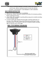
Installation Instructions & User’s Manual
Global Lighting Systems
visionxusa.com
www.VISIONXUSA.com
Global Lighting Systems
visionxusa.com
About the 7” LED Headlight:
7” XMC SERIES SPECIFICATIONS
1. Warranty
: Extended
2. Amp Draw
: High 1.5A / Low 1.1A / Halo 0.17A @ 12V
3. Approval
: DOT
4. Beam Patterns : High, Low, Halo
5. LED Lifespan : 50,000 Hours
WARNING: Due to excessive light amount you may need to bring
your light into a dealer to get it properly adjusted. Weight and tire
pressure can affect the position of the light
WARNING: Disconnect battery cables before starting the install to
prevent vehicle start-up or accidental turning on of anything electrical,
which could cause death or serious injury.
WARNING: Disconnect negative battery wire first. If positive wire
makes contact with ground wire connected, the resulting sparks can
cause a battery explosion, which could result in death of serious
injury.
WARNING: An additional step to prevent accidental electrical
shock, which could cause death or serious injury, remove main fuse
before proceeding. Follow the instructions in the service manual to
disconnect the battery cables, negative (1) cable first or remove the
main fuse.
WARNING: After installing seat, pull upward on seat to be sure it is
locked in position. While riding, a loose seat can shift making it hard
for the rider to keep control of the motorcycle.
Global Lighting visionxusa.com
Systems
SEE VEHICLE OWNERS MANUAL FOR HELP REPLACING HEADLIGHT
ADDITIONAL WIRING HARNESS ADAPTER MAY BE NEEDED
CONSULT YOUR DEALER TO DETERMINE IF ONE IS NEEDED
HALO WIRING INSTRUCTION
1. Disconnect vehicle battery prior to installation
2. Review your vehicle manual for detailed instructions for removing existing
factory head light housing.
3. Attach XMC LED Headlight to existing factory plug and re-install according
to your vehicles manual.
4. To wire the LED Halo Daytime Running light, locate the white wire on
the back of the XMC light. Power the white wire by attaching it to the
accessory power of the vehicle if there isn’t accessory power available
affix it to the blue wire of the XMC.
XMC-7RD WIRING DIAGRAM
Global Lighting Systems
visionxusa.com
Headlamp Alignment
1
2
3
STEP 1: Low Beam
STEP 2: Center line of Low Beam
STEP 3: High Beam
TESTING THE LIGHT
1. After all connections have been made start your vehicle and test your
switch to make sure it turns on the light prior to reassembly of the faring.
2. Make sure the angle of your light is correct, otherwise adjust the light
angle again.
3. Make sure no wire or other components of the harness are exposed to
water spray, excessive heat, or moving parts.
TIP: Vision X recommends checking each bolt and nut, as well as the
connectors after driving your vehicle for an extended period of time to ensure
that each light is securely mounted.


![4403002491_712_716 menu_EN_A [s]](http://vs1.manualzilla.com/store/data/005650300_1-96030b29e24dd373b0bced3bef593dda-150x150.png)