1
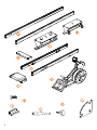
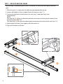
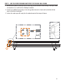
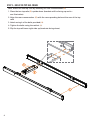
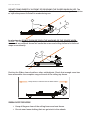
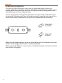
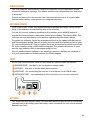
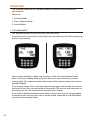
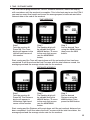
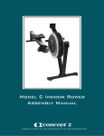
ASSEMBLY MANUAL
OWNER’S MANUAL
MONITOR MANUAL
2
ASSEMBLY MANUAL
The Slider is shipped in 2 boxes. The main large rectangular box contains the front
flywheel unit of the machine, the seat, front and rear legs and some loose parts for the
rail assembly. The long box contains the rails for both the moving top frame and stationary
base frame.
Be sure to find a safe and spacious area to limit risk of damage while assembling
the Slider.
While it is possible to assemble the Slider with one person, it is recommended that you
have the help of a second person for the lifting stages of the assembly.
Assembly should take approximately 20 - 30 minutes.
Additional Tools Required: Phillips head screwdriver.
COMPONENTS
Base Rails, 1LH & 1RH
Front Assembly
Front Leg
M8 x 16mm for Crossmember (x4)
Rear Leg
Rubber Bump Stops (x6)
Crossmember
Socket Ratchet Tool
Top Rails, 1LH & 1RH
Locking Plate Knob
Seat
Rail Locking Plate
3
STEP 1 - BUILD THE BASE RAIL FRAME
The first step in assembling the Slider is to attach the front and rear legs to the base
rails.
1.Place the rails (A) apart with the bolts (already attached) facing up.
2.Loosen all 8 bolts so there is about 5mm of clearance (see 1.1).
3.Line up the keyholes to the bolts on the rear leg (C) and front leg (B) as
shown below.
NOTE:
The rear leg (C) will go on the bolts with the narrow part of the keyhole closest to the
end of the rails (See 1.2).
The front leg (B) will have the wheels positioned toward the front of the rails (see 1.3).
4.Hand-tighten all bolts, then tighten with the ratchet (J).
5.Flip over the base rail frame.
1.2
1.3
5mm
1.1
4
STEP 2 - ADD THE FRONT RUBBER BUMP STOPS TO THE BASE RAIL FRAME
1.Remove the plastic end caps at the rear leg end of the base rails using a Phillips head
screwdriver (or a drill with a Phillips head bit).
2.Insert one rubber bump stop (I) into the guide channel of each rail and slide all the
way to the front end caps.
3.Leave the end caps off ready for the attachment of the top rail frame.
5
STEP 3 - BUILD THE TOP RAIL FRAME
Next, attach the two top rails by installing the rear crossmember(D).
1.Place the two top rails (E) upside down (brackets will be facing up and in see illustration)
2.Align the rear crossmember (D) with the corresponding holes at the rear of the top
rails
3.Attach using 4 of the bolts provided (H).
4.Tighten the bolts using the ratchet (J).
5.Flip the top rail frame right side up (brackets facing down).
6
STEP 4 - ATTACH THE TOP RAIL FRAME TO THE BASE RAIL FRAME
1.Carefully lift the top rail frame (E) and align to the guide channels on the base rail
frame (A).
2.Gently roll the top rail frame forward onto the base rail. (Inserted correctly the top rail
frame should roll easily on the base rail frame.)
Check that the rear guide
brackets on the top rail frame
locate into the guide channels
7
STEP 5 - ADD THE REAR RUBBER BUMP STOPS TO THE BASE RAIL FRAME
1.Insert one rubber bump stop (I) into the guide channel of each rail and slide towards
the rear brackets.
2.Replace the plastic end caps to the base rails using a Phillips head screwdriver (or a
drill with a Phillips head bit).
STEP 6 - ADD THE LOCKING PLATE
1.Take the locking plate and attach it to the inside of the left base rail using the threaded
knob provided.
2.Turn the knob until it is tightened all the way.
3.Turn the plate to the locked position for the remainder of the assembly.
LOCKED
8
UNLOCKED
STEP 7 - ADDING THE SEAT & RUBBER BUMP STOPS TO THE TOP RAIL
1.Remove the plastic end caps at the rear end of the top rails using a Phillips head
screwdriver or cordless drill (see 8.1).
2.Slide the seat (F) onto the top rail frame (E) making sure the seat brackets locate into
the guide channels.
3.Insert the two remaining rubber bump stops (I) into the guide channel
4.Replace the end caps to the rear of the top rails (see 8.2).
8.1
8.2
9
STEP 8 - MOUNTING THE FRONT ASSEMBLY TO THE TOP RAIL FRAME
1.Loosen the 4 bolts (already attached) from the top rail frame so there is about 5mm of
clearance (see 9.1).
2.Carefully place front assembly (G) onto the top rail frame (E), making sure to line up
keyholes to the loosened bolts.
3.Once front assembly has been placed into the correct position, push it towards the
front of the Slider to lock into place.
4.After double checking the locking plate is in the LOCKED position, slowly stand the
slider up (see 9.2).
5.Tighten the 4 bolts with the ratchet (see 9.3).
5mm
9.1
10
9.2
9.3
STEP 9 - ADDING THE BUNGEE TRAVELLER TO THE FRONT LEG
The last step in the assembly process is to attach the bungee cord. The cord is located on
the lower front of the front assembly.
1.Undo one of the bolts that attach the eyelet to the front leg using a Phillips head
screwdriver (or drill bit).
2.Slip the loop end of the bungee into the eyelet.
3.Tighten both bolts to secure the bungee in place.
Congratulations, the Slider assembly is now complete!
Please read the Owner’s Manual before using the Slider for the first time.
11
OWNER’S MANUAL
SAFETY
The following are some general use recommendations to ensure the safest and optimal
operation of the Slider.
CHAIN AND HANDLE
The chain and oar handle must be kept in good condition to prevent any reduction in
performance of the machine, increased wear, and/or risk of failure, which could result
in injury to the user. Check the condition of the chain regularly (particularly the swivel
attachment where the chain and the U bolt on the handle meet). If the hole in the swivel
becomes worn or the U bolt weakened, contact your Slider distributor for replacement
parts. Recommendations to prolong the life of the chain and components are:
•
Do not release the handle until it is resting against the handle holder or the
chain faring. Letting the handle fly back to the chain faring could damage the
links in the chain, chain connector swivel, handle, chain faring and/or the STM
workout monitor.
•
Use both hands to pull back on the handle. One-hand rowing causes sideload
on the chain and connector, which can compromise the structural strength of
these parts.
•
Never twist chain or pull from side to side.
Please note: Abuse of the chain can result in injury.
5mm
LOCKING THE ROLLING FRAME
DO NOT USE THE SLIDER IN THE LOCKED POSITION. To do so will cause damage to the
rail frames and weaken the locking mechanism.
LOCKED
UNLOCKED
Keep locked for
STORAGE and MOVING
Keep unlocked while
Slider is in use.
MOVING AND STORING IN AN UPRIGHT POSITION
The Slider has wheels located on the front legs to help move the machine. ALWAYS PUT
THE FRAME LOCK IN THE LOCKED POSITION
BEFORE MOVING THE SLIDER. Once the rolling
frame is locked, lift the rear of the machine to
engage the front wheels on the ground. Wheel
the machine into position and stand the machine
upright on the front end. Only store the machine
upright on a level and even surface.
12
ROLLING FRAME
DO NOT STAND DIRECTLY IN FRONT OF OR BEHIND THE SLIDER WHEN IN USE. The
rolling frame has a long range of travel in both directions and can damage the machine
or injure the person if contact is made during use.
As a bystander, DO NOT PUSH OR TOUCH THE MACHINE OR THE ROWER WHEN
IN USE. The rolling frame is highly responsive to the momentum generated by the
rower and any external forces can cause the rower and rolling frame to hit the end
stops unnecessarily.
Position the Slider clear of walls or other solid objects. Check that enough room has
been allowed for the complete range of travel of the rolling top frame.
Keep 10 feet, 6 inches free from obstructions.
GENERAL SAFETY PRECAUTIONS
•
•
Keep all fingers clear of the rolling frame and seat frame.
Do not wear loose clothing that can get stuck in the wheels.
13
OPERATION
SETTING THE LEVEL OF THE BASE RAIL
The rear leg of the Slider base frame has an adjustable height system that
compensates for uneven floor surfaces. The Slider needs to be set exactly level for
optimal performance and to prevent the moving frame from rolling more to one
end of the base rail frame than the other.
The two large knobs located at the top of the rear leg are used to adjust the level
of each side of the base rail. Turn the knobs to raise or lower the rear leg until the
base rails are level (indicated by the spirit level located between the knobs).
TURN RIGHT
TO LOWER
TURN LEFT
TO RAISE
Make sure the height adjuster knobs on each side are set at the same level as one
another so the weight of the Slider is evenly distributed.
When moving the Slider to a new location, check that the base rail frame is still set
level before using again.
14
GETTING STARTED
Set your feet to the preferred height and tighten the straps. Turn on the monitor and set
the resistance by moving the lever on the side of the flywheel.
The top rail should be in the center before taking the first stroke.
If you hit the end stops at the very first stroke, the rolling top frame was too close to one
end before starting. Stop, center the rolling frame and start again in the center of the
range of travel.
The Slider responds to how smoothly you transfer your body weight during the drive
and recovery phases of the stroke cycle and rewards consistency in technique.
ONE LEG ROWING TECHNIQUE
To get a good understanding of how the Slider works, row with one leg only. Place one
leg on the footplate and the other on the floor outside the base frame. Use the foot
placed on the floor to hold the seat position stationary relative to the floor. Then, while
holding the handle, push the front of the machine away. Take a few strokes to get the
rhythm and range of movement with the one leg rowing. When ready, place the other
leg onto the footplate and try rowing normally.
OBJECTIVE
The objective is to keep the movement of the seat relative to the floor to a minimum,
letting the rolling frame of the Slider do all of the moving. Ideally check your technique
by using a mirror, reflection in the window or video.
If you consistently move toward one end of the machine:
•
•
Be sure the Slider is level.
Coordinate your recovery technique.
(Keep legs straight until the handle has gone past the knees on the recovery.
Bending the knees early in the recovery generates momentum forward on the
seat and subsequently on rolling frame - causing it to move closer to the front
end of the machine.)
•
Keep in mind, the bungee will help action the rolling frame back toward the
center and away from the end stops.
•
Row 1/2 slide until you stay in the same spot, then lengthen.
15
MAINTENANCE
We suggest the following maintenance procedures be conducted to keep the
machine working in optimal condition.
1. Wipe the Slider frame and flywheel assembly with a soft cloth and light detergent
spray after use. Pay particular attention to keeping the rails clean to avoid build up
of dirt and sweat on the seat rails.
2. Periodically oil the chain using 20w Motor Oil or 20w 3-in-1 oil.
3. Regularly inspect the condition of the chain for any stiff links. If oiling the chain
does not loosen the link, the chain should be replaced.
4. Periodically inspect the oar handle, U Bolt and chain swivel connection for wear.
If there is significant wear of the U Bolt or the hole in the connector swivel is
elongated, contact us for a replacement chain and swivel assembly or U Bolt.
5. Periodically examine the drive system inside the front assembly for any wear on
the sprockets and idlers. This check can be performed with a visual examination
from opening the front cover of the machine. Replace parts if worn or damaged.
6. Periodically open the flywheel housing to clean the flywheel and housing mesh of
dust using a vacuum cleaner bristle head or soft cloth.
7. If the handle does not return all the way to the Chain Faring, tension the bungee
cord using the procedure set out in the Service Manual located on our website.
TROUBLESHOOTING
All troubleshooting solutions are explained in the Service Manual on our website.
Here are some quick reference troubleshooting topics.
- THE ROLLING FRAME TENDS TO ROLL TOWARD ONE END OF THE BASE FRAME MORE THAN THE OTHER.
The base frame might not be level. Check the level of the base frame and
adjust if necessary.
- THE CHAIN BECOMES SLACK DURING THE RECOVERY AND WON’T RETURN INTO THE DRIVE ASSEMBLY.
1.The bungee needs tensioning.
2.Replace bungee if necessary.
- THE CHAIN SEEMS TO BE NOISIER THAN BEFORE.
1. Oil the chain.
2.Check the chain for stiff joints or damage.
3.Replace chain if necessary.
4.Check to see that the chain is running correctly on all sprockets and idlers
by opening the front cover.
16
- THE ROLLING FRAME DOESN’T MOVE AS FRICTIONLESS AND AS FREELY AS IT USED TO.
1. Check for dirt and other objects on the base rail.
2.Check for dirt and other objects on the rollers.
3.The wheel bolts are too tight and need slight loosening.
4.The wheels have become worn and need replacing.
5.The bearings are worn and need replacing.
- THE RESISTANCE SEEMS TO BE LIGHTER
The flywheel and housing may have collected a lot of dust and will need
cleaning so the correct amount of air can flow through the system.
Again, for detailed repair instructions, please visit our website.
WARRANTY
I. FRAME
Slider will replace or repair, at its option, the Slider frame if it fails due to a
defect in material or workmanship for a period of 3 years from the date of initial
shipment.
PARTS
Slider will replace or repair, at its option, the Slider parts that fail due to a defect in
material or workmanship for a period of 2 years from the date of initial shipment.
The replacement Slider frame and/or parts will be warranted for the remainder of
the original warranty period or 2 years, whichever is longer.
II. WHO IS PROTECTED
This warranty is enforceable by the original purchaser and fully transferable
to subsequent owner(s) if transferred within the term of the warranty. Proof of
purchase is required for all warranty claims.
III. WHAT IS NOT COVERED
This warranty does not cover the following:
•Any Slider that has been modified without permission
• Damage, deterioration or malfunction resulting from:
- failure to follow user manual included with the Slider
- accident, abuse, misuse, neglect, fire, water, or acts of nature
- repair or attempted repair by anyone not authorized by Slider
- shipping or transport damage (claims should be made with the carrier)
- any other cause which does not relate to a material or workmanship defect
• Deterioration due to normal wear and tear
• Damage to the finish of the Slider
• Removal, installation, shipping, customs or any other incidental charges
Slider does not warrant that the Slider will meet your requirements. It is your
responsibility to determine the suitability of the Slider for your purpose.
17
IV. WARRANTY CLAIMS
To make a warranty claim, take the following steps:
1. Contact Slider to inform the problem with the Slider. You will need to provide a clear
description of the problem and your proof of purchase.
2.If your warranty claim relates to a part which can be safely replaced by you, we will
send out such a part to you by post.
3.If Slider provides you a return, package the Slider or the relevant parts securely
(preferably in its original packaging) and ship in prepaid as instructed by Slider,
clearly stating RAN number and your full contact details. ANY RETURNS WITHOUT A
VALID RAN NUMBER WILL NOT BE ACCEPTED. Slider will not be responsible for any
damage during shipping.
V. GENERAL
(a) To the maximum extent permitted by law:
• Slider shall not, in any event, be liable for any incidental, indirect, special or
consequential damages;
• these warranties are in lieu of any other express or implied, including
but not limited to, any warranty relating to merchantability or fitness for a
particular purpose; and
• the duration of implied warranties in limited to the length of warranty
specified in paragraph I above.
(b) This warranty gives you specific legal rights. You may also have other rights granted under local laws of your country. These rights may vary in different
countries.
SPECIFICATIONS
Length: 213 cm or 84 inches or 7 feet
Dynamic Length Max: 322 cm or 127 inches or ≈10.6 feet
Width: 56cm or 22 inches or ≈1.8 feet
Height stood upright: 213cm or 84 inches or 7 feet
Weight: 45kgs or 100 lbs
SERIAL NUMBER
Record your serial number here for easy reference on any service issues. The
slider serial number can be found on the back of the footboard.
18
S/NO MONITOR MANUAL
CONTENTS
Features
Technical Functions
Software Updates
Ports
Batteries
Training Modes
Just Row Mode
Time and Distance Workouts
Interval Workouts
Time Repeat Intervals
Distance Repeat Intervals
Custom Workout Intervals
Workout Memory
Troubleshooting
19
FEATURES
The Slider Training Monitor (STM) is a professional workout monitor that has a number
of display and training features specific for rowing.
DEFAULT SCREEN
The default display is set to show:
Time
Stroke Rate
Speed as Time/500m
Distance
GETTING STARTED
To get the monitor started each time you use the
machine, press the ON/OFF button.
To reset the monitor at any time, press the ON/OFF
button twice to turn the monitor off and then back on
again.
SPEED
Speed can be displayed as:
Time/500m
Watts
Km/Hr
Miles/Hr (M/Hr)
Metres/Second (M/S)
Change units of Speed by pressing the SPEED button.
AVERAGE
Average display field shows:
Av. Time/500m
Av. Watts Av. Km/Hr
Av. Miles/Hr
Av. Metres/Second
Stroke Count
(or clear field)
Change Units of Average by pressing the AV button
20
TECHINICAL FUNCTIONS
Press the TECH button to access these features. The Technical information is
displayed in the bottom left hand field on the display.
Technical functions display field shows:
DRIVE RATIO
STROKE LENGTH
AVERAGE STROKES PER MINUTE
HEART RATE
DRAG
(or Clear Field)
Change Technical features by pressing the TECH button
DRIVE RATIO
The drive ratio is a ratio of drive time to recovery
time. The drive phase is always measured as 1. For
example, if the drive time was 1 second and the
recovery time was 3 seconds, the drive ratio would be
displayed as 1:3.0. If the drive time is 0.7 secs and the
recovery time was 2.8 secs the drive ratio would be
displayed as 1:4.0.
STROKE LENGTH
Stroke Length is a numerical value given to the
length of the drive phase of the rowing stroke. The
measurement is based on the amount of flywheel
revolutions from the beginning to the finish of
the stroke and converted into a number for easy
reference. The numerical value is a reference
number only. It does not represent a length in
centimeters or inches or an arc length but is very
useful for setting a target length you wish to reach.
AVERAGE STROKES
PER MINUTE
This feature displays the average strokes per
minute from the commencement of a Just Row or
programmed workout.
HEART RATE
The STM is compatible with the Ant+ brand of heart
rate chest belts and receivers. The Heart Rate
receiver plugs into the port at the rear of the monitor.
When the STM is receiving the signal the Heart icon
will flash on and off.
The heart rate receiver must be set within 3 feet of
the chest belt worn by the rower to be within range of
the signal.
21
DRAG
The Drag feature is a numerical value given to the
rate of deceleration of the flywheel. With a heavy
resistance setting, the flywheel decelerates quicker
and therefore the drag value is high. A lighter
resistance, a lower drag value.
This Drag value is calculated every stroke and used
in the algorithm to produce the rowing speed. This
Drag feature compensates for dust accumulation in
the flywheel housing and atmospeheric conditions
(Temperature, Altitude, Wind) which can affect the
rate of deceleration of the flywheel. For example, a
setting of 4 on one machine may need a setting of 5
on another to achieve the same level of resistance on
both machines. Using the drag value instead of the
resistance lever number is the best way to calibrate
each machine to be the same resistance.
This feature is more used for performance testing
where it is important that all machines are set to an
equal resistance, so that each rower is tested under
the same conditions.
To measure the drag value for a given resistance,
press the TECH button until the Drag is shown. Row
3 to 4 strokes continuously and the monitor will
calculate the drag for that resistance setting. Adjust
the resistance lever up or down until the desired drag
value is set.
22
OTHER FEATURES
The STM uses the advanced self calibration algorithm to give consistent scores
across all resistance settings. This allows scores to be comparable from machine
to machine.
To save on battery life, the monitor has a time out function set at 3 minutes after
the last button action, rowing stroke or completed workout.
SOFTWARE UPDATES
From time to time, Slider will release software updates that might rectify unseen
bugs in the software or add functionality to the monitor.
To view the current software installed on the monitor, press ARROW UP button to
activate the Interval field in the bottom centre of the display. Then press READY. The
software version will display in the bottom right display field shown below.
To update the software, follow the procedure set out in the update pdf that comes
with the software update. You will initially have to install the update drivers to your
PC running Windows XP, Vista or higher. Once the drivers are installed connect the
PC to the monitor using a USB cable and update. This should take about 30 secs
and the new software will be uploaded ready for use.
We will send software updates to our existing customers as they are released or
they will be available to download from the Slider website.
PORTS
On the rear of the monitor there are four ports for specific cable connection.
SENSOR PORT - this port is for the flywheel sensor cable
HR PORT - this port is for the Heart Rate receiver
USB PORT - for connecting the monitor to a computer via a USB-B cable
NETWORK PORT - for connecting to other monitors (not currently configured)
BATTERIES
The Slider Workout Monitor uses 4 AA standard batteries and access to the battery
compartment is by sliding open the battery cover located at the rear of the monitor
beneath the Ports.
23
TRAINING MODES
The STM has a selection of 3 workout modes for different training sessions
and methods.
These are:
1.Just Row Mode
2.Time / Distance Mode
3.Interval Mode
1. JUST ROW MODE
The simplest function of the STM is the Just Row mode.
Turn the monitor on and start rowing. Both time and distance will start counting up
until you stop rowing.
You can stop rowing for a short rest, stretch or drink. Once the flywheel slows
down, the screen display fields will pause after your last stroke until you start
rowing again. The elapsed workout information will be preserved and start where
you last stopped.
If you stop for longer than 3 minutes before rowing again, the monitor will timeout
and you will lose your current workout information. The monitor will reset back to
zero when you turn the monitor back on again after timeout.
If you wish to display additional information on the screen such as average speed
or technical data such as heart rate or stroke length, press the AV and TECH buttons
to activate these display fields.
24
2. TIME / DISTANCE MODE
The STM can be programmed for Time or Distance workouts, where the display
will countdown until the workout is complete. This is the best way to use the STM if
you want an exact final result and to see the average speed, stroke rate and other
relevant data at the end of the workout.
TIME WORKOUT
Step 1
Turn the monitor ON.
Press TIME. The Time
digits will appear in the
top left hand corner of
the monitor.
Step 2
The flashing digit will
be editable using the
ARROW UP button. To move
to the next digit across
use the ARROW ACROSS
button.
Step 3
Set the desired Time
using the ARROW buttons,
then press the READY
button.
Start rowing and the Time will count down until the set workout time has been
completed. It will then show the final F screen with the total distance rowed, the
average speed and the average stroke rate for the workout.
DISTANCE WORKOUT
Step 1
Turn the monitor ON.
Press DIST. The Distance
digits will appear in
the bottom right hand
corner of the monitor
Step 2
The flashing digit will
be editable using the
ARROW UP button. To move
to the next digit across
use the ARROW ACROSS
button.
Step 3
Set the desired
Distance using the
ARROW buttons, then
press the READY button.
Start rowing and the Distance will count down until the set workout distance has
been completed. It will then show the final F screen with the total time taken, the
average speed and the average stroke rate for the workout.
25
3. INTERVAL WORKOUTS
The STM can be programmed for interval training with a set work time or distance
and rest period in between. It can either repeat the set work and rest period or be
programmed as a customized workout with variable work times, distances and
rests. The first workout will begin when the first rowing stroke is taken. It will then
run through the programmed intervals and repeats until complete.
On completion, the monitor will display the final F screen with total time taken,
total distance rowed and average time/500m for the entire interval workout.
The Memory function of the STM has recorded the workout data for each individual
work interval and these can be viewed by using the ARROW buttons. The interval
number in the bottom centre display field will show the corresponding interval
number in the series.
The STM will store the most recent interval workout until a new workout has been
programmed and started. If the timeout turns the monitor OFF, the most recent
workout can be recalled by turning the monitor ON and pressing the MEMORY
button, then using the ARROW button to scroll through the work interval.
During the rest period, only the rest time is displayed and a beep countdown is
activated in the last 5 seconds to lead into the next work period in the series.
26
TIME REPEAT INTERVALS
Step 1
Turn the monitor
ON. Press INTERVAL.
Interval 1 will appear
on the bottom centre
display field.
Step 2
Press TIME
Step 3
Set the work value
using the ARROW button
then press READY.
Step 4
The Rest field will
automatically appear
and become editable.
Step 5
Set the rest time
using the ARROW
buttons. Press READY
to lock in rest time.
The rest period can
be set to zero if there
is no rest period
needed between
intervals.
Step 6
The set work time
and rest time can
now be repeated so
that the workout is
made up of a series of
the set work and rest
periods.
Step 7
To enter the number
of repeats, press the
TECH button. Use the
ARROW buttons to set th
enumber of repeats,
then press READY.
Step 8
Once the work, rest
and repeats are set
and programming is
complete, press READY
a final time to set
the monitor ready to
begin.
27
DISTANCE REPEAT INTERVALS
Step 1
Turn the monitor ON.
Press INTERVAL. Interval
1 will appear on the
bottom centre display
field.
28
Step 2
Press DIST
Step 3
Set the work value
using the ARROW button
then press READY.
Step 4
The Rest field will
automatically appear
and become editable.
Step 5
Set the rest time using
the ARROW buttons.The
Rest period can be set
to zero time if there is
no Rest period needed
between intervals.
Step 6
Press READY. The set
work distance and
rest time can now be
repeated so that the
workout is made up of
a series of the set work
and rest periods.
Step 7
To enter the number
of repeats, press the
TECH button. Use the
ARROW buttons to set
the number of repeats
then press READY.
Step 8
Press READY a final time
to prpare the monitor
to start.
Workout Ready
Display is now set to
start the workout.
The countdown will
commence on the
first stroke.
CUSTOM INTERVAL WORKOUT
The STM can be programmed for a variable time, distance and rest workout. This
function gives the STM the versatility to be used to replicate an on-water session or
allow the workout to be divided into sections for a rest break in between work periods
ie. 30mins rowing/10 mins rest/30 minutes rowing. Other examples of using this
custom interval workout feature are to set incrementing work times or distances ie
4min/3min/2min/1min or numerous other combinations.
SETTING A CUSTOM INTERVAL WORKOUT
Example below - Time and Distance combination:
Interval 1: 5mins warm up/No rest
Interval 2: 5000m row/2 min rest
Interval 3: 5mins warm down/No rest
Step 1
Turn the monitor ON.
Press INTERVAL. Interval
1 will appear on the
bottom centre display
field.
Step 2
Press TIME Set the work
value using the ARROW
button then press READY.
Step 3
The Rest field will
automatically appear
and become editable.
Set the rest time using
the ARROW buttons.
Step 4
Press READY to enter
the rest period. The
editing of Interval 1 is
complete.
Step 5
Press the ARROW ACROSS
key to move to entering
the values for Interval
2. Interval 2 will appear
on the bottom centre
display field.
Step 6
Press DIST. Set the work
value using the ARROW
button then press READY.
29
30
Step 7
Set the rest time using
the ARROW buttons.
Step 8
Press READY to enter the
rest period. The editing
of Interval 2 is complete.
Step 9
Press the ARROW ACROSS
key to move to entering
the values for Interval
3. Interval 3 will appear
on the bottom centre
display field.
Step 10
Press TIME. Set the work
value using the ARROW
button then press READY.
Step 11
Set the rest time using
the ARROW buttons.
Step 12
Press READY to enter
the rest period. The
editing of Interval 3 is
complete.
REVIEWING A CUSTOM INTERVAL WORKOUT BEFORE STARTING
Before pressing READY prior to commencing the workout, the custom workout can
be reviewed by using the ARROW buttons.
To edit any of the set intervals press either TIME or DIST to activate the field. If you
want to change from Distance or Time mode for that interval, press the relevant
TIME or DIST button and edit using the ARROW buttons. Press READY to confirm
the new interval values. When the setting or editing of the custom interval workout
is complete, press READY a final time to lock in the workout and prepare to row.
Please note that once the final READY is pressed the workout is no longer editable
and the workout will have to be reprogrammed if changes are required.
When all of the intervals are complete, press READY to prepare the monitor to
begin. The monitor will display Interval 1 and wait until the first stroke before
commencing countdown.
Workout Ready
Display is now set to start the workout.The countdown will commence on the first
stroke.
31
WORKOUT MEMORY
The STM has a memory feature that stores the workout information of the most
recent programmed time, distance or interval workout.
On completion of the programmed workout the monitor will display an F screen
showing the final results of the workout.
The STM also records split results for a set time or distance split ie 2000m workout
can record the split results for every 500m, giving a total of 4 splits to compare.
Each split is numbered for reference.
To scroll through splits, use the ARROW button. To scroll through Averages and other
information in the AV display field in the top right of the screen, press the AV button.
The STM will store the results of the most recent workout until another workout is
programmed. Once the monitor has been reset the previous workout information
is erased.
If the monitor powers down, the memory can be recalled by turning the monitor ON
and pressing the MEMORY button.
On completion of the
2000m workout, the
STM will display the
final results as an F
screen.The information
shown will be total time
taken, average speed
in time/500m and the
average strokes per
minute.
32
Press the ARROW
buttons to move from
the F screen to the
Splits that show the
results for each split
segment. In this case
every 500m. (See
Setting the Splits)
Split Interval 1
Split Interval 2
Split Interval 3
Split Interval 4
WORKOUT MEMORY (CONTINUED)
Example 2 - 4 x 1min/30secs rest Interval
On completion of the
Interval workout the
STM will display the
final results as an F
screen.The information
shown will be total time
taken, average speed
in time/500m and the
average strokes per
minute.
Press the ARROW
buttons to move from
the F screen to the
Intervals showing
the results for each
Interval segment.
Split Interval 1
Split Interval 2
Split Interval 3
Split Interval 4
33
SETTING THE SPLITS
The split units can be set from the split presets of 30 secs, 45secs, 1 min, 2min,
100m, 250m, 500m, 10 strokes, 20 strokes. The split must be set prior to the
commencement of the workout. The STM will default to the set split unit until it
is changed.
Step 1
Turn the monitor ON. Press Time or Distance.
Edit the workout Time or Distance or press TECH to
change the Split Preset.
Step 2
Use the ARROW buttons to scroll though the Preset Split
options.
Step 3
Select the Split Preset by pressing READY. Edit the
workout or if already set, press READY to prepare to start
the workout.
34
TROUBLESHOOTING
- MONITOR NOT GIVING ANY SCORES. READING ZEROS WHEN ROWING.
1.Check the sensor is plugged in and in the correct port.
2.Check pulses procedure. If no pulses continue with steps 3 & 4.
3.Check for damage to the cable.
4.Contact your local Slider agent for further advice or replacement cable.
- MONITOR NOT TURNING ON.
1.Replace batteries.
2.If the batteries have been replaced with new and in date batteries and
still does not turn on contact your local Slider agent for further advice or
replacement monitor.
- MONITOR GIVES IRREGULAR SPEED AND RATINGS.
1.Check pulses procedure. If there is a regular pulse at low speed check again
at a progressively higher flywheel speed. Listen for consistency of beeps as
the speed of the flywheel increases.
2.If there are inconsistent beeps it means that the sensor is not detecting the 3
magnets per revolution and therefore producing some irregular scores and
ratings.
3.If this is the problem you identify please contact your local Slider agent for
further advice.
CHECK PULSES PROCEDURE
1.Turn monitor ON.
2.Press the ARROW UP button. The small interval digits should appear in the
centre bottom field of the display.
3.Press the ARROW UP until the digit reads 01, then press READY. The top right
corner field should then show a number digit only.
4.Lightly pull the handle to get the flywheel moving. The flywheel contains
3 evenly spaced magnets and as each magnet passes over the monitor
sensor, there should be a beep. ie. 3 beeps per revolution.
5.Try moving the flywheel faster and listen for an even and consistent beep
pattern.
6.If hearing an irregular pattern of beeps or missing beeps please contact your
local Slider agent for further advice.
35
United States
560 Metacom Avenue | Warren, RI 02885
Tel: +1 (401) 247 7745 | sliderdynamic.com
United Kingdom
19 Acton Park Estate | The Vale, London W3 7QE
Tel: +44 (0) 20 87 49 84 00 | crockeruk.com
SL7005
© 2014 WaterRower