1
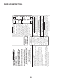
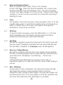
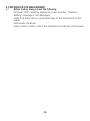
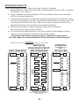
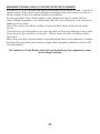
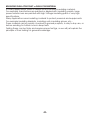
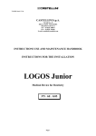
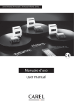
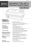
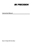
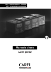
TIN7D
DIGITAL, VARIABLE,
HIGH VOLTAGE,
INSULATION TEST METER.
TABLE OF CONTENTS
Index.................................................................................
Front Panel Layout..............................................................
Inside Lid Instructions..........................................................
Safety precautions...............................................................
Overview............................................................................
Features.............................................................................
Connections........................................................................
Specifications......................................................................
Functions............................................................................
Special Features..................................................................
Preparation for Measurement...............................................
Maintenance and Cleaning Method.....................................
Insulation Resistance Testing................................................
Typical Applications of Insulation Testing...............................
Limited warranty.................................................................
-2-
2
3
4
5-8
9
10
11
12
13-15
16-17
18
19
20
21-23
24
P16
2
AUTO-RANGING
-3-
INSULATOR
TM
TM
TEST
START / STOP
With EnerSave
ON
1KV
+
500V
2.5KV
VOLTAGE
ADJUST
5KV
8
4
5
3
7
6
1
EnerSave is the default mode. EnerSave limits the test duration.
AUTO-OFF
TM
To disable EnerSave , depress "TEST" for more than 3 Sec while
TM
starting a new test. The Short Beep while depressing mean EnerSave is OFF
TM
OFF
500V
10KV
MICROPROCESSOR CONTROLLED
MODEL TIN7D
FOR DAR and PI TESTS,
ALWAYS DEPRESS TEST
FOR MORE THAN 3 SEC.
EARTH
GUARD
INSULATION
LINE
EARTH
OUTER SHEATING
COVERING
Note:
LINE
In some cases,
Readings on NON
PURE RESISTIVE
Loads may be
Unstable.
+HV
SAFETY PRECAUTION!
LINE
CABLE CORE
GUARD
INSULATION
+HV terminal
SEE PAGES 13 to 17 FOR
EXPLANATIONS
ALWAYS READ USER'S MANUAL BEFORE OPERATING THIS INSTRUMENT.
– Use only on de-energised and isolated / disconnected system.
DO NOT PROCEED IF VOLTAGE PRESENT !!!
– Check test leads for defects. If any cracks or damages, replace with new test
leads of Same specifications.
– Always earth circuit under test.
– After testing, allow a few seconds for instrument to discharge circuit under
Test. Follow discharge on the display.
OPERATING INSTRUCTIONS
1. Depress "ON" .
2. Insert leads into the instrument observing color coding.
3. Clip GREEN lead to earth . Connect Guard to collect surface leakage current.
4. Select test voltage and follow display instructions.
CAUTION
5. Touch RED lead to other side of circuit under test . Stop test immediately if
warning message and/or buzzer sounds. This indicates the presence of an
external voltage which must be removed. Before proceeding again, reset the
tester by depressing "ON"
6. Connect RED lead to other side of circuit under test and Depress "TEST" to
start and stop the test (tests up to 10 minutes when EnerSave TM is off).
7. Display shows test duration, real time bargraph voltage indication and
Insulation Resistance, after 1 Min, the DAR and after 10 Minutes, the PI.
DAR
PI
GUARD
GUARD terminal
AUTO-OFF
10kV VARIABLE DIGITAL
INSULATION TESTER
L.C.D.
AUTOMATIC POLARISATION INDEX AND DIELECTRIC ABSORPTION RATIO
EARTH
-HV
-HV terminal
0. FRONT PANEL LAYOUT and INSIDE LID INSTRUCTIONS.
FRONT PANEL LAYOUT
-4-
SAFETY !
– The circuit under test must be de-energized AND isolated
before insulation test are made.
– Check Test Leads for Defects, they must have good, unbroken
insulation, uncontaminated by grease, oil or dirt.
– For optimal results, only use supplied Test Leads.
– To avoid creating leakage path when insulation testing, it is
advisable not to allow the leads to twist together nor trail
accross metalwork etc., more than is really necessary. If this
can't be avoided, only the Optional, Proprietary, Very High
Voltage, Coaxial Silicone Test Lead could give best results.
– Make sure to Earth Circuit under Test.
– Wait until display shows "HOLD" before removing the test
Leads.
CAUTION !
– Instrument used in dusty environment should be send only,
to an approved maintenance laboratory for periodic cleaning.–
The instrument contains static sensitive devices. If opened for
any reason, the warranty will be invalidated.
ENERSAVE MODE
– saves battery life by Automatically turning
The Instrument to Low Consumption and
reducing the test duration.
– is the default mode of the Instrument.
– is enabled when pressing the "TEST" button
for less than 3 seconds while starting the
test.
– is disabled when pressing the "TEST" button
for more than 3 seconds while starting the
test (user to disable for PI and DAR tests).
When The ENERSAVE Mode is disabled, the
Instrument Operates Continuously (up to
99.9s).Testing can be interrupted at any time by
depressing Test Start/Stop key.
Discharge Always Applied automatically.
WARNING !
This instrument should
not be used in explosive
or inflammable
environments, although
there is unlikely to be a
fire hazard from the
instrument itself.
However, arcing in
faulty insulation,
sparking caused when
making or removing
connections to
equipment that has not
been properly deenergized, or discharge
of capacitance
following tests, can all
lead to explosion or fire
hazard.
Insulation Tester
Specified with
Alkaline Batteries.
EARTH
GUARD
LEAKAGE
LINE
INSULATOR
TYPICAL TEST
Preventive Maintenance :
when the results are entered into the logbook, a considerable
variation between the tests could be noted. It is therefore
important to test under similar conditions each time and to note
the current weather status. Damp conditions can cause large
reductions in insulation resistance. Temperature of the equipment
under test should also be noted.
FOR DAR and PI TESTS, ALWAYS DEPRESS
TEST FOR MORE THAN 3 SEC.
PI =POLARIZATION INDEX
DAR = DIELECTRIC ABSORPTION RATIO
RESISTANCE MEASURED AT 1 MINUTE
RESISTANCE MEASURED AT 30 SECONDS
RESISTANCE MEASURED AT 10 MINUTES
PI=
RESISTANCE MEASURED AT 1 MINUTE
DAR=
USE THE GUARD !
This Instrument has an Integral Guard
Circuitry to Minimise the measurement
errors introduced by surface leakage
current.
During insulator testing, for example; a
leakage path may exist between the
connection to the line conductor and
the connection to the earth conductor
due to dirt or moisture contamination.
Where this possibility exist, particularly
when testing at higher voltages, a
bare conductor may be bound tightly
around the insulator and connected
to the guard terminal as shown. The
guard test lead is provided with
alligator for this purpose. The leakage
current is then going into the guard
connection instead of having it's path
in parallel with the measurement.
Without the Guard, Insulation
resistance appears lower than with the
Guard.
INSIDE LID INSTRUCTIONS.
1. SAFETY PRECAUTIONS.
SAFETY RULES
CAUTION
RISK OF ELECTRIC
SHOCK
This tester has been designed with your safety in mind. However, no
design can completely protect against incorrect use. Electrical circuits
can be dangerous and/or lethal when lack of caution and/or poor
safety practices are used.
Do not carry out field measurements on either the power system
grounding, during periods of forecast lightning activity, or any non
insulated system or non insulated circuit. In the event that lightning
occurs, stop all testing and isolate and remove any temporarily
installed test spikes or test leads.
Preparations for testing of power system grounding or close to it can
leave personnel vulnerable to exposure caused by faults at or fed from
the system under test, transferred potentials from remote test grounds,
and inadvertent line energizations. Always insulate the device under test.
While the probability of the occurrence of one of these events is low,
personnel safety will, nevertheless, be enhanced by the following:
When working near high tension systems rubber gloves and shoes
should be worn.
Work on clean, dry crushed rock or an insulating blanket.
Avoid bare hand to hand contact between the tester and extended
test leads.
When using the tester with test leads, ensure that they are safe and
properly authorized
Disconnect the tester from any external circuit when checking or
changing the Fuse and/or batteries.
CAUTION
READ THE MANUAL
Follow the instructions in the Manual for every measurement. Read and
understand the general instructions before attempting to use this tester
-5-
SAFETY CHECK
Before using the tester check the condition of the test leads and the
fuses. If using fused test leads.
The test leads must be free of cracks or any damages and must be
insulated as when they were new.
Always disconnect the test leads when changing the batteries by
removing the cover which give access to the batteries.
Always double check the lead connections before making any
measurements.
For increased safety, use fused test leads (optional).
DON'T TOUCH
Don't touch exposed wiring, connections or other "Live" parts of an
electrical circuit. If in doubt, check the circuit first for voltage before
touching it.
Do not use cracked of broken test leads.
THIS INSTRUMENT SHOULD ONLY BE USED BY A COMPETENT, SUITABLY
TRAINED PERSON.
REMEMBER
SAFETY IS NO ACCIDENT
CAUTION RISK OF ELECTRIC SHOCK
CAUTION READ THE MANUAL
-6-
Electricity can cause severe injuries even with low voltages or currents.
Therefore it is extremely important that you read the following
information before using your Variable High Voltage Digital Insulation
Meter.
1.1
This instrument must only be used and operated by a competent
trained person and in strict accordance with the instructions and
safety practices.
We will not accept liability for any damage or injury caused by
misuse or non compliance with instructions and safety procedures.
1.2
This instrument must not be used on live circuits. Ensure all circuits are
de-energized before testing. See paragraph 1.7 for details of builtin warning features should your Variable High Voltage Digital
Insulation Meter be connected to a live system.
1.3
Never open your Variable High Voltage Digital Insulation Meter
except for battery replacement. (See Battery Replacement
section).
1.4
Always inspect your Variable High Voltage Digital Insulation Meter
and test leads before using for any sign of abnormality or
damage. If any abnormal conditions exist (broken test leads,
cracked case, display faulty etc...) do not attempt to take any
measurement or use the tester.
Return your Variable High Voltage Digital Insulation Meter to your
nearest distributor for service.
1.5
Your Variable High Voltage Digital Insulation Meter has been
designed with your safety in mind. However, no design can
completely protect against incorrect use.
Electrical circuits can be dangerous and/or lethal when a lack of
caution or poor safety practice is used.
Use caution in the presence of voltage above 24V as these pose
a shock hazard.
1.6
Pay attention to cautions and warnings which will inform you of
potentially dangerous procedures.
-7-
1.7
Your Variable High Voltage Digital Insulation Meter has a live
circuit warning beeper. If It is connected to a live circuit, a rapid
pulsating bleep will be heard.
DO NOT proceed to test and immediately disconnect the
instrument from the circuit. In addition your tester will
display the warning message.
-8-
2. OVERVIEW.
This digital insulation tester is a variable high voltage insulation meter
from 500 V to 10KV in 500V steps.
Its output voltage can be adjusted using 500 V up or down steps.
The meter is menu driven and uses Dynamic Current Auto-ranging
technology.
It is equipped with a bar-graph which displays the voltage stressing the
insulation while the test is in progress.
This bar-graph is showing voltage output during the first 30 seconds of
the test or during automatic discharge of circuits.
During the automatic discharge of the circuit tested, the bar-graph
displays the voltage decay.
The display shows the elapsed time since the start of the test.
Digital readout of the total time remains displayed even after testing
has ceased.
A 6 digit digital display is showing the actual Insulation Resistance.
This instrument displays and sounds a voltage warning when AC or DC is
present before injecting the test voltage.
The warning circuit can only detect when voltage is higher than 500V .
This Variable High Voltage Digital Insulation Meter will buzz intermittently
when high voltage is generated and this will remain until the circuit
under test is fully discharged.
-9-
3. FEATURES.
2 x 16 characters, large, High Contrast, Intelligent L.C.D. Module.
20 Insulation test voltages
500V, 1KV, 1.5KV, 2KV, 2.5KV, 3KV, 3.5KV, 4KV,
4,5KV, 5KV, 5.5KV, 6KV, 6.5KV, 7KV, 7.5KV, 8KV,
8.5KV, 9KV, 9.5KV, 10KV.
Calculate Dielectric Absorption Ratio (DAR) Automatically.
Calculate Polarization Index (PI) Automatically.
Insulation resistance Auto-Ranging on all ranges.
TM
Ener-Save .
Bar graph indicates test voltage. Rise and decay can be observed.
Warning of external voltage presence(>500Vac or Vdc).
Overload protection.
Low battery indicator (real time battery Voltage Measurement).
Measure insulation time duration of the test.
Low battery consumption.
Smart microprocessor controlled.
One year factory warranty.
Better than 10% accuracy on all ranges.
Auto-off.
Compact and lightweight.
-10-
4. CONNECTIONS.
INSULATOR
-HV
10kV VARIABLE DIGITAL
INSULATION TESTER
EARTH
GUARD
-11-
+HV
LINE
5. SPECIFICATIONS.
Test Voltage
From 500Vdc to 10KVdc
Adjustable in 500 V Steps
Preset Buttons
1KV, 2.5KV, 5KV, 10KV
Measuring Range
800K -500G
AUTO-RANGING
Accuracy
± 5% ± 2 digits
Power
8 x 1.5V Alkaline batteries
Output Power Limit
1W
Voltage Regulation
Selected Voltage +20%-5% of nominal value
unless current limited. Meaning that if output
current is too high, the voltage will be lowered
automatically.
Accessories
Color coded flexible silicone test
leads and instruction manual.
Special Standard Accessory on this model
Anti-leakage, Color coded,
Flexible silicone coaxial test lead
with integrated guard, into the test
probe.
-12-
6. FUNCTIONS (see FRONT PANEL LAYOUT).
6.1
Power-On
To switch your instrument on, press the "ON" button
( 1 ). The L.C.D. will display the model number.
Follow interactive instructions on L.C.D..
6.2
Insulation Resistance Measurement @ 10kVdc.
To Select 10KVdc test voltage, press 10KV button ( 2 ).
6.3
Insulation Resistance Measurement @ 5KVdc.
To Select 5KVdc test voltage, press 5KV button ( 4 ).
6.4
Insulation Resistance Measurement @ 2.5KVdc.
To Select 2.5KVdc test voltage, press 2.5KV button ( 5 ).
6.5
Insulation Resistance Measurement @ 1KVdc.
To Select 1KVdc test voltage, press 1KV button ( 6 ).
Insulation Resistance Measurement @ Multiple of 500Vdc adjustment
To add 500Vdc to the selected test voltage,
press +500V button ( 7 ).
To subtract 500Vdc to the selected test voltage, press -500V
button ( 8 ).
6.6
6.7
Ener-SaveTM mode.
The Ener-Save TM mode saves battery life by automatically
turning the instrument to low consumption (reducing the test
duration ).
The Ener-Save TM mode is the default mode of the instrument.
The Ener-Save TM mode is enabled when pressing the TEST button
( 3 ) for less than 3 Seconds .
The Ener-Save TM mode is disabled when pressing the TEST button
( 3 ) for more than 3 seconds.
When Ener-Save TM mode is disabled, the instrument operates in
continuous mode (up to 10 minutes) .
6.8
Voltage Output Bar-Graph. The bar-graph shows the voltage
present on the leads. It also shows the voltage charging a cable
or capacitive system under test and shows the decay during the
automatic capacitive discharge of the system under test.
-13-
6.9
Auto-Low Resistance Detect.
While in insulation test mode, if the L.C.D. Module
shows "LOW M ", stops the test immediately. This could mean
that the insulation has a breakdown, thus, you are now trying
to inject very high voltage on a short circuit. Trying to inject high
voltage on a short circuit could reset the instrument (specially if
flashing Occurs).
6.10
Timer.
The duration of the test is shown on the top right of the L.C.D. This
is particularly useful to verify that insulation does not break down
within a certain time or to make comparison. See Special
Features for more Timer Functions.
6.11
STOP test.
To stop the test in progress, press the TEST button ( 3 ). The test
will immediately stop, discharge and the instrument will reenable the Ener-Save TM mode automatically.
6.12
Auto-Stop.
Should the operator leaves the Instrument in the test mode with
the Ener-Save TM disabled, theinstrument will automatically stop
the test after a duration of 10 minutes.( Auto-off still applies ).
6.13
Auto Live / Voltage Warning.
Should the leads be placed onto a live system before starting
the test, a warning beeper will be automatically activated and
your instrument will display " Live Warning ... Circuit Live .. "
message.
Let the instrument discharge the circuit ( in the case of
capacitive system) or make sure that the circuit under testing is
not live .
6.14. Auto - Discharge.
At auto-stop or test completion, the instrument automatically
discharges the system under insulation test so that the
dangerous high voltage is discharged. The auto-discharge can
be observed on the L.C.D.'s bar graph so that the operator only
removes the leads when the discharge is complete.
-14-
During discharge, a beep occurs so that the user does wait for
the complete discharge of the system under test. This is
indicated by a one second long beep accompanied by the
"HOLD" message on the display.
DO NOT REMOVE LEADS UNTIL THE HOLD MESSAGE APPEARS
ON THE DISPLAY.
6.15
"Replace Battery" Warning Indicator.
If the battery energy is detected to be too low, the instrument will
display the "Battery" warning.
The instrument cannot operate properly with a low battery.
6.16
Auto-Off.
The Auto-off is annunciated by a one second beep. The Autooff timer is automatically enabled.
The instrument can also be switched off by pressing and holding
the OFF key for more than 5 seconds.
-15-
7. SPECIAL FEATURES.
7.1
DAR = Dielectric Absorption Ratio.
The dielectric Absorption Ratio is the ratio of the Insulation
Resistance measured at 1 Min divided per the Insulation
Resistance measured at 30 Seconds.
30 Seconds after starting a test (with EnerSave disabled), the
tester will beep, indicating the operator that the resistance value
measured at 30 second now has been saved internally.
1 Minute after starting a test (with EnerSave disabled), the tester
will beep again, indicating the user that the DAR result is now
computed, and change the display format to now display the
DAR result.
7.2
PI = Polarization Index.
The Polarization Index or PI is the ratio of the Insulation Resistance
measured at 10 Minutes divided per the Insulation Resistance
measured at 1 Minute.
10 Minutes after starting a test (with EnerSave disabled), the
tester will beep again, indicating the user that the PI result is now
computed, and change the display format to now display the PI
result.
The tester will Auto-Stop at 10 minutes.
7.3
Digital Display.
The digital Liquid Crystal Display is large. It measures
(W)98mm x (H)24mm and has a 2 Lines of 16 Characters.
Language can be changed on demand, as an option.
Dutch / French / German etc... (factory fitted at order)
7.4
Automatic Battery Test.
When the tester starts, it test it's batteries by drawing a heavy
current from the batteries. During that heavy current, it
measures the battery voltage and displays it for a few seconds
on the display. During normal use, the tester monitors the battery
voltage, but without drawing a battery test current. It just
measures the battery while in normal use.
-16-
7.5
Automatic Discharge of Capacitive and Inductive Circuits
This tester will discharge automatically all circuits charged by
the tester, after a test is done, again, this will only be activated if
the test leads make contact at any time before, during and
after the test.
It's your responsibility to ensure proper contact of the leads at all
times.
Once a test is finished, the testers will automatically discharge
capacitive or inductive circuit of their charge. The discharge
can be observed on the display, in the form of a bar-graph.
Again, do not disconnect the leads while discharging. Wait until
completion of the discharge before removing any lead.
During discharge, the Buzzer will beep and the bar-graph will
show some voltage. With some high charges, this may take
some time. Be patient and let the instrument discharge
completely before proceeding to removing the leads.
-17-
8. PREPARATION FOR MEASUREMENT
8.1
Before testing, always check the following:
At Power "ON", read the display to make sure the " Replace
Battery" message is not displayed.
Verify that there are no visual damage to the instrument or test
leads.
Test Leads continuity:
Using a Ohm-meter, check the resistance/continuity of the leads.
-18-
9. MAINTENANCE AND CLEANING METHOD.
9.1
Battery Replacement.
Your insulation tester's battery is situated under the tester.
The display will indicate when battery needs to be replaced.
Disconnect the test leads from the instrument and removes the
battery cover and the batteries.
Replace with eight ALKALINE 1.5V "C"size, taking care to observe
correct polarity.
Replace battery cover.
9.2
Cleaning & Storage.
Periodically wipe the case with a damp cloth and detergent.
Do not use abrasives or solvents.
If the meter is not to be used for long periods or longer than 60
days, remove the batteries and store them separately.
Warning
To avoid electrical shock or damage to the meter,
do not get water inside the case.
Store the meter in a dry environment.
9.3
Calibration & Servicing
Both, calibration and servicing are performed only at an
approved facility. Contact your nearest distributor about
calibration certificate and servicing .
Before returning the instrument, ensure that :
the leads have been checked for continuity and
signs of damage.
the batteries are in good condition.
-19-
10. Insulation Resistance Testing .
Warning : Insulation test should be conducted on circuits that
are de-energized.
Ensure circuits are not live before commencing testing.
– Secure both test leads properly to the insulation to test and use
guard lead to collect surface leakage.
– Good contacts are necessary to avoid flashing at high voltage
or ionization or creation of carbon track type conductive
material.
– If contacts are not properly secured, the tester may be
corrupted temporarily by the high electromagnetic field
present. Should this occur, let it reset itself.
– Use only battery ( Alkaline ) to power this instrument .
DO NOT USE ANY KIND OF ADAPTER OR CONNECTION TO THE MAINS POWER.
-20-
MEASURING AN INSULATOR
When measuring insulator, there are a few things to consider:
1- Most insulators collect dust and get contaminated over time with a mixture
of Moisture, rain, dirt etc...
2- These matters lower the resistance of the insulator as they are in parallel
with the insulator resistance.
3- It is recommended to measure the insulator first without the guard to verify
that the total resistance is high. Should the total resistance not be high, that
could mean that the amount of dirt on the surface of the insulator is too
high and therefore, the insulator may require cleaning.
4- Should your insulator require cleaning, follow the procedures
recommended by it's manufacturer.
5- For Final Test and Measurement, use the Guard so that leakage surface
current is collected and Insulator is intrinsically tested.
The insulator must not be connected to any live component or power source.
Use a tied copper wire around the insulator at about its center to connect the guard.
FIRST MEASUREMENT
MEASURE WITHOUT THE GUARD TO TAKE EVERYTHING INTO ACCOUNT AND FIND OUT IF NEED CLEANING.
DIRTY INSULATOR
LINE
ELECTRICAL
EQUIVALENT CIRCUIT
DIRTY INSULATOR
LINE
TYPICAL TEST
LINE
LEAKAGE
RESISTANCE
DUE TO
CONTAMINATION
INSULATOR
INSULATOR RESISTANCE
LEAKAGE
DUE TO
CONTAMINATION
EARTH
SECOND MEASUREMENT
MEASURE WITH THE GUARD
TO ENSURE INSULATOR IS
CORRECT.
EARTH
GUARD
INSULATOR
EARTH
RESISTANCE DUE TO CONTAMINATION CAN BE VERY LOW
AND LOWER THE TOTAL RESISTANCE.
CLEANING PERIODICALLY CNA ALSO REDUCE SYSTEM
POWER CONSUMPTION.
-21-
MEASURING THE INSULATION OF A CONTACTOR OR CIRCUIT BREAKER
Contactor or Circuit breaker are switching devises which when closed, must do a
good contact (have the lowest resistance possible) and when open, must be a
good insulator (have the highest resistance possible).
As they get older, their characteristics may deteriorate due to many factors.
Their material properties may deteriorate with time and frequency use as well as
stress put on to them.
One of the factor we will be testing is their insulation when acting as an open
circuit.
Contactors or circuit breakers may also get dirty as they are utilized in heavy duty
environments, like factories, mines etc.., Which have climatic conditions which
are harch.
When they are dirty, their insulation may deteriorate due to the deposit of matters
between the terminals (see previous page about parasitic resistance due to dirt
contamination).
The Contactor or Circuit Breaker must not be connected to any live component or power
source during its testing.
-22-
MEASURING INSULATING PAINT or INSULATING MATERIAL
In many applications, paint is utilized as an important insulating material.
For example, transformers are painted or dipped with insulating varnish, large
power transformers are painted with High Voltage insulating paint of very high
specifications.
Many Applications uses insulating material to protect personal and equipments.
For example insulating blankets, insulating suits, insulating gloves, etc...
These material can be quickly checked to general purpose, in day to day use, or
before sending for further more in deep tests.
Testing these can be tricky and require proper test jigs, so we will just explain the
principle of their testing for general knowledge.
-23-
LIMITED WARRANTY
We warrant the product manufactured by us to be free from defective
material or factory workmanship and agree to repair or replace this
product which, under normal use and service, disclose the defect to
be the fault of our manufacturing, with no charge for parts and service.
If we are unable to repair or replace this product, we will make a full
refund of the purchase price.
Consult the user's manual for proper instruction regarding use of this
instrument.
Our obligation under this warranty is limited to repairing, replacing or
making refund of this test equipment which proves to be defective
within twelve months from the date of original purchase.
This warranty does not apply to any of our products which have been
repaired or altered by unauthorized persons in any way so as, in our
sole judgement, to injure their stability or reliability, or which have been
subject to misuse, abuse, misapplication, negligence or accident or
which have had the serial numbers altered, defaced or removed.
Accessories, not of our manufacture used with this product, are not
covered by this warranty.
All warranties implied by law are hereby limited to a period of twenty
four months, and the provisions of the warranty are expressly in lieu of
any other warranties expressed or implied.
The purchaser agrees to assume all liability for any damages or bodily
injury which may result from the use or misuse of the product by the
purchaser, or its user, his employees, or others, and the remedies
provided for in this warranty are expressly in lieu of any other liability we
may have including incidental or consequential damages.
We reserve the right to discontinue models at any time, or change
specification, price or design, without notice and without incurring any
obligation.
-24-