1
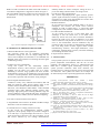
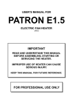
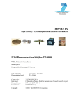
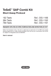
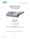
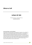
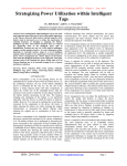
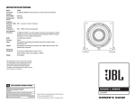
International Journal of P2P Network Trends and Technology –Volume 16 Number 1 – Feb 2015 Universal Analog Frontend for Industrial Temperature Measurement Shobha Nikam #1,Yogesh Patil #2,Kaustubh Rajvaidya#3,Vinay Kumar#4 1 Assistant Professor, Department of Electronics Engineering AISSMS’s IOIT, SPPU, Pune, Maharashtra, India 2,3,4 Student , Department of Electronics Engineering AISSMS’s IOIT, SPPU, Pune, Maharashtra, India Abstract—In industrial environments, high-temperature measurements are required for process control, safety evaluation, reliability prediction, product liability, and quality control. Temperature is one of the most measured parameters within industry and science. A correct measurement is of great importance to the quality of the product, as well as to security and to energy consumption. Therefore, it is very important to choose the right sensor for the actual application. However, a 100% ideal solution for a measuring job is difficult to find if not to say impossible. The choice will often be a compromise between the requirements of the user and the limitations set by the sensor types that are suitable for the conditions at the measuring point. To choose the right temperature sensor and the right method to transmit temperature data is the most important task. Having chosen the optimal temperature sensor for a measuring task, next step in remote temperature measurement is to send information from the temperature sensor to the control room. Connecting the thermocouple or the resistance thermometer directly with a cable can do this, or you can have a transmitter placed close to the temperature sensor, from which an amplified signal is sent to the control room. But this can introduce errors. Our project incorporates the use of a signal conditioning circuitry that is compatible to different kinds of temperature sensors thus overcoming the above drawbacks. Universal analog front end is a compact field mountable modular system which directly interfaces thermocouple/ RTD sensors of a particular instrumentation and control system, performs signal conditioning with high accuracy & precision and transmits data over mod bus/RS-232 to a control & monitoring system with Elipse E3 SCADA software. Every temperature measurement application has different performance requirements and it is important to know exactly what errors exist in your system and how your resolution is being affected by noise. Even more useful is the ability to customize your measurement settings to tune your system to your specific accuracy, resolution, and sampling rate needs. Temperature Accuracy required ±5°C ±1°C ±0.5°C ±0.1°C -200°C care needed difficult difficult very difficult 0°C to 50°C easy care needed difficult very difficult 1000°C care needed very difficult extremely difficult almost impossible 2000°C very difficult extremely difficult almost impossible don't even try Fig1. Table showing difficulty of temperature measurement over a range of temperatures. Keywords— High temperature measurement, quality control, optimal temperature sensor, signal conditioning circuitry, compact field mountable, high accuracy & precision. II. DESCRIPTION AND WORKING PRINCIPAL Different temperature sensors require different signal conditioning circuitry. Our project incorporates the use of a signal conditioning I .INTRODUCTION Monitoring temperature is a widespread and common circuitry that is compatible to different kinds of temperature engineering task. Whether in a laboratory or factory, sensors .It supports all types of thermocouples with cold performing accurate, high-resolution, temperature junction compensation and any type of RTD (resistance measurements can be difficult and expensive. Most commonly, temperature detector) with resistances up to 4 kΩ for 2-, 3-, or a simple thermocouple is used along with a data 4-wire connection configurations. The RTD excitation current acquisition device and some kind of signal conditioning is programmable for optimum noise and linearity hardware . It is a surprisingly difficult parameter to measure performance. Thermocouples and RTDs (resistance temperature detectors) are the most frequently used sensors with the precision that one might reasonably expect. To obtain accuracies better than 0.2°C (0.4°F) great care in for temperature measurement in industrial applications. needed. Errors occur due to the presence of temperature Thermocouples are able to measure very high temperatures up gradients, drafts, sensor nonlinearities, poor thermal contact, to about +2300°C and also have a fast response time calibration drifts, radiant energy and sensor self-heating. (measured in fractions of a second). RTDs are capable of Generally the accuracy of all sensor types can be greatly higher accuracy and stability than thermocouples, and the resistance of long wire lengths (hundreds of meters) to a improved by individual calibration. ISSN: 2249-2615 http://www.ijpttjournal.org Page 1 International Journal of P2P Network Trends and Technology –Volume 16 Number 1 – Feb 2015 remote RTD can be compensated for with 3- or 4-wire connections. RTD measurements achieve 0.1°C accuracy (typical), and Type-K thermocouple measurements achieve 0.05°C typical accuracy because of the 16-bit ADT7310 digital temperature sensor used for cold-junction compensation. The circuit uses a four-channel AD7193 24-bit sigma-delta ADC with on-chip PGA for high accuracy and low noise. Input transient and overvoltage protection are provided by low leakage transient voltage suppressors (TVS) and Schottky diodes. The SPI-compatible digital inputs and outputs are isolated (2500 Vrms), and the circuit is operated on a fully isolated power supply. Fig.2.Schematic of signal conditioning circuitry [1] We have connected the board to a low cost PIC24FV16KM202 microcontroller and further to ADM3251E which is a high speed, 2.5 kV fully isolated, single- channel RS-232/V.28 transceiver device that operates from a single 5 V power supply. Due to the high ESD protection on the RIN and TOUT pins, the device is ideally suited for operation in electrically harsh environments or where RS-232 cables are frequently being plugged and unplugged. The ADM3251E incorporates dual-channel digital isolators with isoPower™ integrated, isolated power. There is no requirement to use a separate isolated dc-to-dc converter. We have also used Elipse Software, E3 which is a powerful platform for supervising and controlling processes fully focused on network operation and distributed applications. E3 is a SCADA (Supervisory Control and Data Acquisition) system that offers an advanced object model, a powerful graphical interface, in addition to an architecture allowing fast application development and maximum connectivity to devices and other applications. Systems built with E3 usually start from real time data collection from data or control acquisition devices, such as PLCs (Programmable Logic Controllers), RTUs (Remote Terminal Units), DAQs (Data Acquisition Boards), Multi-Loop or Single-Loop controllers, fire centres and weighing machines, among other devices. These equipment’s usually have some interface allowing its connection to the software, such as standard serial RS232, ISSN: 2249-2615 RS422, or RS485 boards directly linked to the computer bus, and others. E3 reads and writes data from the equipment through modules (I/O Drivers) that implement the protocol available in each one of them (public or private domain). These Drivers can still be in an Elipse Software format or in OPC format (OLE for Process Control). With this data, users can create many ways to display, analyse, control, command, store, or disclose such information, among them: Screens: allows creating an HMI (Human-Machine Interface) locally, through local network or Internet, aiming at displaying current or past data status in many ways, using a graphical editor and specific objects Alarms and Events: monitors the occurrence of specific situations Historics: stores data in relational databases Reports: allows viewing and printing data, among other modules and possibilities. III. DESIGNING OF THE CIRCUIT We have designed the whole PCB in ORCAD capture and PCB EDITOR .The flow of design is as follows: 1. Generate initial drawings. 2. Collect data sheets. 3. Draw the schematic (placing and connecting parts). 4. Perform a Capture design rule check (DRC) to verify that the circuit schematic has no issues. Correct any errors and repeat DRCs as needed. 5. Generate a bill of materials to identify PCB assigned and missing footprints. 6. Search through the PCB Editor libraries to find and assign footprints. For any footprints that are unavailable, obtain the data sheets for recommended land patterns and design the footprints using PCB Editor and the Pad stack Designer. 7. Generate a PCB Editor net list and open the board design. 8. Define the board requirements. 9. Auto routing 10. Finalizing the design: Fig 3. Screenshot of a footprint made in PCB editor IV. WORKING OF THE SYSTEM This proposed system uses the AD7193, low noise, 24-bit sigma-delta ADC to ensure high resolution and linearity for the entire circuit. [1] http://www.ijpttjournal.org Page 2 International Journal of P2P Network Trends and Technology –Volume 16 Number 1 – Feb 2015 The AD5201, 33-position digital potentiometer, AD8603 op amp, and ADG702 single channel switch constitute a simple programmable current source and bias voltage buffer for the RTD and thermocouple measurements. The ADG738 routes the current source to the active RTD channel and allows wire resistance compensation for the 3-W RTD configuration. The ADT7310 digital SPI temperature sensor has ±0.8°C maximum accuracy (+5 V supply) from −40°C to +105°C and is used for cold-junction compensation for the thermocouple measurement. The ADR3440 is a low noise and high accuracy 4.096 V reference connected to REFIN1(+)/REFIN1(−) of the AD7193 for the thermocouple measurements. input impedance and limits the input leakage current to ± 3 nA maximum. The gain of theAD7193 must be configured properly depending on the temperature range and type of sensors. The on-chip multiplexer allows four differential input channels to be shared with the same ADC core, saving both space and cost. Programmable Current Source for RTDs and Bias Voltage Generator Circuit for Thermocouples RTD measurements require a low noise current source that drives the RTD and a reference resistor. Thermocouple measurements, on the other hand, need a common-mode bias voltage that shifts the small thermocouple voltage into the input range of the AD7193. The circuit meets both requirements and utilizes the AD8603 a low noise CMOS railto-rail input/output op amp with only 1 pA maximum input bias current and 50 μV maximum offset voltage, combined with the ADG702 single channel, CMOS low voltage 2 Ω SPST switch, and the ADG738 eight-channel matrix switch. With the ADG738 opened and the ADG702 closed, the AD8603 acts as a low noise, low output impedance unity-gain buffer for the thermocouple application. The voltage from the AD5201 digital potentiometer is buffered and is used for the thermocouple common-mode voltage, usually 2.5 V, which is one-half the supply voltage. The 33-position AD5201 digital potentiometer is driven with the ADR3440 low drift (5 ppm/°C) 4.096 V reference for accuracy. With the ADG738 closed and the ADG702 opened, the AD8603 generates the RTD excitation current. Fig.5. External programmable current source and bias voltage generator. Fig 4. Schematic of the proposed system made in ORCAD capture The AD7193 is a low noise, complete analog front end for high precision measurement applications. It contains a low noise, 24-bit sigma-delta (Σ-Δ) analog-to-digital converter (ADC). This ADC achieves high resolution, low non-linearity, and low noise performance as well as very high 50 Hz/60 Hz rejection. The data output rate can be varied from 4.7 Hz (24 bits effective resolution, Gain = 1), to 4.8 kHz (18.6 bits effective resolution, Gain = 1). The on-chip low noise PGA amplifies the small differential signal from the thermocouple or RTD with a gain programmable from 1 up to 128, thereby allowing a direct interface. The gain stage buffer has high ISSN: 2249-2615 Temperature measurement is a high precision and low speed applications, therefore there is adequate settling time available to switch the single current source between all 4 channels, providing excellent channel-to-channel matching, low cost, and small PCB footprint. The ADG738 is an 8-to-1 multiplexer that switches the current source between channels. In order to support the 2-, 3, and 4-wire RTD configurations, each of the four channels need two switches. In many applications, the RTD may be located remotely from the measurement circuit. The resistance from the long lead wires can generate large errors, especially for low resistance http://www.ijpttjournal.org Page 3 International Journal of P2P Network Trends and Technology –Volume 16 Number 1 – Feb 2015 RTDs. In order to minimize the effect of the lead resistance, a 3-wire RTD configuration is supported as shown in Figure 3. The 4-wire RTD connection requires two extra sense lines, but is insensitive to wiring resistances and only requires one measurement. Fig 6. Connector and jumper configuration for a 3 wire RTD IV. BENEFITS OF THE PROPOSED SYSTEM: 1. Match the Best Sensor to the Application : The proposed system has an intelligent temperature transmitter strategy, the user can simply change out the sensor and reconfigure the transmitter to accommodate the different sensor type without even touching the main signal conditioning circuitry. 2. Enhance Accuracy and Stability: Using this system we can substantially enhance measurement accuracy. DCS and PLC systems measure readings over the entire (very wide) range of a sensor. Measuring a narrower range produces far more accurate measurements. System can be calibrated to any range within a sensor’s overall capabilities. Their measurements are more precise than is possible with most direct wiring strategies. 3. Protect Signals from Plant Noise: Common in nearly every industrial environment, RFI and EMI can negatively affect process signals. Some of the common sources include mobile and stationary radio, television, and hand-held walkie-talkies; radio-controlled overhead cranes; radar; induction heating systems; static discharge; high-speed power switching elements; high AC current conductors; large solenoids and relays; transformers; AC and DC motors; welders; and even fluorescent lighting. 4. Provides continuous 2500 Vrms Isolation. 5. Programmable Current Source for RTDs and Bias Voltage Generator Circuit for Thermocouples. 6. Transients and over voltage protection circuitry In this circuit, the PTVS30VP1UP transient voltage suppressor (TVS) quickly clamps any transient voltages to 30 V with only 1 nA typical leakage current at 25°C. A 30 V TVS was chosen to allow for a 30 V dc overvoltage. A 1.69 kΩ resistor followed by low leakage BAV199LT1G ISSN: 2249-2615 Schottky diodes are used to clamp the voltage to the 5 V power rail during transient and dc overvoltage events. 7. Avoids errors due to ground loops The systems input/output/power signal isolation protects against signal inaccuracies caused by ground loops. This is important even when using ungrounded TCs because their insulation will eventually break down. 8. Reduced hardware In our system we have used ADG738 which is an 8-to-1 multiplexer that switches the current source between channels. In order to support the 2-, 3-, and 4-wire RTD configurations, each of the four channels need two switches. 9. Avoid Lead Wire Imbalances In our system we can use 4 wires RTD input. The advantage is that the fourth wire in an RTD circuit effectively cancels out errors due to resistance imbalances between the leads. Every ohm of imbalance in an RTD sensor’s lead wires can produce as much as a 4.7F (2.6C) error in the measurement. Serious imbalances may be present from the very first day of commissioning without the user even being aware of them. Typical causes include manufacturing variances, lead length differences, loose connections, terminal block corrosion, and work hardening from bending and other stresses. 10. Open lead wire detection. V . CONCLUSION The proposed system is an optimal solution for accurate and precise temperature measurements with the use of most popularly used temperature sensors i.e. Thermocouple and RTD with a common signal conditioning circuitry. This system provides continuous 2500 Vrms Isolation, has transients and over voltage protection circuitry and open lead wire detection. This system also makes use of Elipse E3 SCADA which provides a powerful graphical user interface. REFERENCES [1]Analog devices,CN-0287 Circuit Note ,Isolated 4 channel thermocouple/RTD measurement system with 0.5 C accuracy. [2]Adler, C.B., ―Reliability Aspects of Temperature Measurement,‖ Instrumentation, Systems, and Automation Society Conference, Chicago, 2001. [3]Bediones, D. and Wang, T.P., ―Criteria for the Selection of Thermocouples Versus RTD’s in Industrial Applications,‖ Paper #91–0300, Instrumentation Systems, and Automation Society, Toronto, 1991. [4] Bliss, P. and Morgan, R.K., ―Errors in Temperature Measurement,‖ Instrumentation Technology, March 1971. [5] Desmarais, R. and Breuer, J., ―How to Select and Use the Right Temperature Sensor,‖ Sensors, January 2001. [6] Kreider, K., ―Thermocouple Research at NIST,‖ Paper #91–0301, Instrument Society of America Conference, Toronto, 1991. [7] Magison, E., Temperature measurement, InTech, October 25, 2001. [8] Langan, P.E. and Ironside, D.S., ―Calibration Ensures Accurate Temperature Measurement,‖ InTech, October 1989. [9] Leewis, W., ―The International Temperature Scale of 1990,‖ Paper #91– 0302, Instrument Instrumentation, Systems, and Automation Society Conference, 1991. [10] Temperature sensors Lipták, B. G.; Rall, D.; Moore, L. W.; Adler, B. // InTech;Aug2004, Vol. 51 Issue 8, p61 [11] Elipse E3 server, studio and viewer E3 user manual. http://www.ijpttjournal.org Page 4