1
LANEX S.A.
8 Ceramiczna street
20-150 Lublin
POLAND
phone no. +48 81 444 10 11
phone/fax. no +48 81 740 35 70
LANWIN
SOFTWARE FOR MONITORING AND CONFIGURING
LANEX DEVICES
USER’S MANUAL
IOALANWIN-1H
February 2006
SOFTWARE FOR MONITORING AND CONFIGURING LANEX DEVICES
USER’S MANUAL
Contents
1
GENERAL CHARACTERISTICS ....................................................................................................................... 1
1.1
1.2
1.3
1.4
1.4.1
1.4.2
1.5
2
PURPOSE........................................................................................................................................................... 1
HARDWARE REQUIREMENTS ............................................................................................................................. 2
EXAMPLES OF APPLICATIONS............................................................................................................................ 2
INSTALLATION AND FIRST RUN ......................................................................................................................... 6
Configuration of communication ports for LANwin application - LOCAL................................................. 9
Configuration of communication ports for LANwin application - NET.................................................... 11
ACCESS CODES ............................................................................................................................................... 12
BASIC PROGRAM’S FUNCTIONS................................................................................................................... 14
2.1
OPTIONS OF APPLICATION’S MAIN WINDOW ................................................................................................... 14
2.1.1
The “List” tab........................................................................................................................................... 14
2.1.2
The “Map” tab......................................................................................................................................... 16
2.1.3
Logical maps............................................................................................................................................. 17
2.1.4
Macro-commands ..................................................................................................................................... 18
2.1.5
Archiving of maps ..................................................................................................................................... 19
2.2
PROGRAM’S CONFIGURATION ......................................................................................................................... 19
2.2.1
The “Program” tab .................................................................................................................................. 19
2.2.2
The “Rack” tab......................................................................................................................................... 20
2.2.3
The “View” tab........................................................................................................................................ 21
2.2.4
The “Shortcuts” tab................................................................................................................................. 22
2.2.5
The “SMS” tab.......................................................................................................................................... 23
2.2.6
The “Parametry” {Parameters} tab ......................................................................................................... 24
3
PROGRAM’S ADDITIONAL OPTIONS .......................................................................................................... 26
3.1
3.2
3.3
3.4
3.5
3.6
3.7
3.8
3.9
3.10
3.11
3.12
3.13
3.14
3.15
3.16
3.17
3.18
3.19
3.20
PROTECTING THE PROGRAM BY A PASSWORD AND ADDING NEW USERS .................................................... 26
SECURITY DEVICE ACCESS PASSWORD .......................................................................................................... 31
REGIONS ......................................................................................................................................................... 33
IDENTIFICATION DATA ................................................................................................................................... 35
PORT IDENTIFICATION .................................................................................................................................... 37
RETRIEVING IDENTIFICATION DATA FROM A LOCAL DATABASE................................................................... 38
EXPORT AND IMPORT OF PROGRAM CONFIGURATIONS ................................................................................. 39
INTERFACE OF EXPORT OF ALERTS TO AN EXTERNAL SYSTEM .................................................................... 39
INTERFACE OF EXPORT OF DATA ON HARDWARE CONFIGURATION TO AN EXTERNAL SYSTEM .................. 41
TRAP SNMP ................................................................................................................................................. 43
PACKET STATISTICS ....................................................................................................................................... 46
PING ............................................................................................................................................................... 47
INVENTORY DATA REPORT............................................................................................................................. 47
ACCESS AUTHORIZATION TRANSFER ............................................................................................................. 49
TERMINAL ...................................................................................................................................................... 50
SQL INTERFACE OF EXPORT OF TRANSMISSION QUALITY PARAMETERS ...................................................... 51
DESCRIPTION OF GRAPHIC SYMBOLS ............................................................................................................. 54
CONFIRMING ALERTS VIA ELECTRONIC MAIL ............................................................................................... 55
REMOTE CONFIGURATION OF TM-47 MULTIPLEXER ..................................................................................... 55
TROUBLESHOOTING ........................................................................................................................................ 57
IOA-LANWIN-1H
I
February 2006
SOFTWARE FOR MONITORING AND CONFIGURING LANEX DEVICES
USER’S MANUAL
List of figures
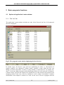
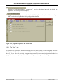
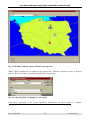
FIG.1 APPLICATION OF MULTIPLEXER TM-47.1-1 COOPERATING WITH SDH RING FOR MANAGING LANEX DEVICES ....... 3
FIG. 2 APPLICATION OF TM-47.1-1 MULTIPLEXER FOR MANAGING LANEX DEVICES VIA WAN.......................................... 4
FIG.3 APPLICATION OF TM-47.1-1 MULTIPLEXER FOR MANAGING LANEX DEVICES VIA SERIAL LINK RS232 ..................... 5
FIG. 4 WINDOW IN WHICH THE USER CAN SELECT A TARGET DIRECTORY WHERE THE APPLICATION WILL BE INSTALLED.... 6
FIG.5. WINDOW IN WHICH THE USER CAN SELECT LANWIN APPLICATION AFFILIATION TO A SELECTED GROUP OF
PROGRAMS ................................................................................................................................................................. 7
FIG.6. WINDOW IN WHICH THE USER IS INFORMED ON THE COURSE OF INSTALLATION PROCESS ......................................... 7
FIG.7. WINDOW IN WHICH THE USER IS INFORMED ON THE RESULT OF INSTALLATION PROCESS .......................................... 8
FIG.8. THE APPLICATION’S MAIN WINDOW AFTER ITS FIRST RUN ......................................................................................... 8
FIG. 9. WINDOW FOR SETTING SERIAL PORT’S SETTINGS ................................................................................................... 10
FIG.10. WINDOW IN WHICH DETECTED DEVICES ARE DISPLAYED ...................................................................................... 10
FIG.11. WINDOW FOR CONFIGURING PARAMETERS OF CONNECTION VIA IP NETWORK...................................................... 11
FIG.12. WINDOW FOR ADDING A NEW CONNECTION .......................................................................................................... 11
FIG.13. THE METHOD OF CONFIGURATION SAVING TO OR READING FROM A FILE .............................................................. 12
FIG.14. WINDOW OF LANWIN APPLICATION WORKING IN A LOCAL MODE WHERE THE USER CAN ENTER ACCESS CODES .. 13
FIG.15. THE PROGRAM’S MAIN WINDOW DISPLAYING THE LIST OF DEVICES ...................................................................... 14
FIG.16. WINDOW INCLUDING BASIC INFORMATION ON THE DEVICE .................................................................................. 15
FIG.17. THE PROGRAM’S MAIN WINDOW WHERE DEVICES ARE PRESENTED IN THE FORM OF A MAP................................... 16
FIG.18. THE PROGRAM’S OPTIONS – THE “PROGRAM” TAB ............................................................................................... 20
FIG.19. THE PROGRAM’S OPTIONS – THE “RACK” TAB ...................................................................................................... 21
FIG.20. THE PROGRAM’S OPTIONS – THE “VIEW” TAB ....................................................................................................... 22
FIG.21. THE PROGRAM’S OPTIONS– THE “SHORTCUTS” TAB ............................................................................................. 22
FIG.22. THE PROGRAM’S OPTIONS – THE “SMS” TAB........................................................................................................ 24
FIG. 23. THE PROGRAM’S OPTIONS – THE “PARAMETRY” TAB .......................................................................................... 25
FIG. 24. WINDOW IN WHICH THE SYSTEM’S ADMINISTRATOR CAN GRANT RIGHTS TO USERS............................................. 26
FIG. 25. WINDOW FOR CHANGING THE CURRENT ACCESS PASSWORD ................................................................................ 27
FIG. 26. WINDOW OF THE WIZARD PROVIDING SUPPORT DURING ADDING A NEW USER TO THE SYSTEM ............................ 27
FIG. 27. WINDOW BY WHICH THE ADMINISTRATOR CAN CHANGE THE RIGHTS OF INDIVIDUAL USERS ............................... 30
FIG. 28. THE WINDOW “PROPERTIES” BY WHICH THE SYSTEM’S ADMINISTRATOR CAN CHANGE THE LOCATION OF THE
RAPORT’S FILE ......................................................................................................................................................... 31
FIG.29. CONTEXT MENU USED FOR DISPLAYING THE INPUT OF THE DEVICE ACCESS PASSWORD ........................................ 32
FIG.30. VIEW OF THE WINDOW USED FOR INPUTTING OR REMOVING DEVICE ACCESS PASSWORD. ..................................... 32
FIG.31. VIEW OF THE WINDOW INFORMING THE USER OF THE DEVICE LOGIN STATUS ........................................................ 32
FIG. 32. WINDOW IN WHICH THE SYSTEM’S ADMINISTRATOR CAN DEFINE HIS/HER OWN REGIONS .................................... 33
FIG. 33. WINDOW WITH THE REGIONS DEFINED BY THE OPERATOR ................................................................................... 34
FIG. 34. ALLOCATING TM-47 MULTIPLEXER TO A REGION................................................................................................ 34
FIG. 35. DEFINING REGIONS TO WHICH A USER HAS ACCESS .............................................................................................. 35
FIG. 36. WINDOW INCLUDING IDENTIFICATION DATA OF A SELECTED DEVICE................................................................... 36
FIG. 37. WINDOW FOR SELECTING GRAPHICS FILES ........................................................................................................... 36
FIG. 38. WINDOW INCLUDING THE USER’S GRAPHICS FILE ................................................................................................ 37
FIG. 39. WINDOW WITH THE INFORMATION ON DEVICE’S DATA TRANSMISSION PORT ....................................................... 37
FIG. 40. WINDOW FOR RETRIEVIENG INFORMATION FROM A SET OF ACTIVE DEVICES ON THE BASIS OF VARIOUS CRITERIA
INCLUDED IN IDENTIFICATION DATA OF A LOCAL DATABASE ................................................................................... 38
FIG. 41. WINDOW FOR EXPORTING CONFIGURATIONS OF LANWIN SOFTWARE ................................................................. 39
FIG. 42. WINDOW FOR WORKING CONFIGURATION OF INTERFACE TO AN EXTERNAL SYSTEM ........................................... 40
FIG. 43. THE CONTEXT MENU FOR OPENING THE PREVIEW WINDOW OF THE STATUS OF CONNECTION WITH EXTERNAL
SYSTEMS .................................................................................................................................................................. 43
FIG. 44. WINDOW IN WHICH THE STATUS OF CONNECTION WITH EXTERNAL SYSTEMS CAN BE CHECKED .......................... 43
FIG.45. VIEW OF THE SET-UP WINDOW WITH TRAP-SNMP INTERFACE PARAMETERS ...................................................... 44
FIG.46. FORMAT OF THE TRAP COMMANDS GENERATED BY THE LANWIN APPLICATION .................................................. 45
FIG.47. VIEW OF THE WINDOW CONTAINING THE DETAILED STATISTICS OF PACKETS SENT AND RECEIVED ....................... 46
FIG.48. VIEW OF THE COMMUNICATION TESTING MODULE WINDOW ................................................................................. 47
FIG.49. VIEW OF THE WINDOWS USED TO GENERATE THE INVENTORY DATA REPORT ........................................................ 48
FIG.50. EXAMPLE OF THE INVENTORY DATA REPORT ........................................................................................................ 49
FIG.51. VIEW OF THE SUCCESSFUL ACCESS AUTHORIZATION TRANSFER MESSAGE WINDOW ............................................. 49
FIG. 52. WINDOW IN WHICH THE SYSTEM’S ADMINISTRATOR CAN DEFINE THE NUMBER OF MAINTAINED REMOTE
CONSOLES ................................................................................................................................................................ 50
FIG. 53. THE CONTEXT MENU FOR OPENING THE PREVIEW WINDOW OF CONNECTION STATUS OF EXTERNAL CONSOLES ... 50
IOA-LANWIN-1H
II
February 2006
SOFTWARE FOR MONITORING AND CONFIGURING LANEX DEVICES
USER’S MANUAL
FIG. 54. WINDOW IN WHICH THE CONNECTION STATUS OF REMOTE CONSOLES CAN BE CHECKED ..................................... 50
FIG. 55. WINDOW OF THE PROGRAM ACTIVATING SQL INTERFACE .................................................................................. 51
FIG. 56. WINDOW WITH INFORMATION ON CONNECTED USERS .......................................................................................... 52
FIG. 57. WINDOW IN WHICH THE PROGRAM’S OPTIONS ARE GATHERED – “ SQL INTERFACE” .......................................... 52
FIG. 58. WINDOW WITH INFORMATION ON TRANSMISSION QUALITY PARAMETERS ........................................................... 53
FIG. 59. WINDOW OF PROGRAM SQLTESTESSES.EXE...................................................................................................... 53
FIG.60. WINDOW WITH INFORMATION ON DEVICES MAINTAINED BY THE SOFTWARE CURRENT VERSION .......................... 54
FIG. 61. THE CONTEXT MENU FROM WHICH THE REMOTE CONFIGURATION WINDOW CAN BE CALLED ............................... 55
FIG. 62. THE WINDOW OF CONFIGURATION OF PARAMETERS OF CHANNELS RS232 OF DEVICE TM47.1-1 ........................ 56
FIG. 63. BUTTONS TO SAVE DEVICE’S CONFIGURATIONS AND EXIT THE PROGRAM ............................................................ 57
FIG. 64. WINDOW CONFIRMING THAT THE OPERATION OF SAVING THE CONFIGURATION TO THE DEVICE HAS BEEN
COMPLETED ............................................................................................................................................................. 57
IOA-LANWIN-1H
III
February 2006
SOFTWARE FOR MONITORING AND CONFIGURING LANEX DEVICES
USER’S MANUAL
Abbreviations
AIS
ETSI
GND
ITU-T
LOSS
LOF
UAL
NUAL
ES
SES
PE
PO
MUX
ALACK
UAL
UALA
NUALA
Alarm Indication Signal
European Telecommunications Standards Institute
Ground
International Telecommunication Union – Telecommunication Standardization Sector
Received signal fading
Loss of frame synchronisation
Urgent alert
Non-urgent alert
Errored seconds
Severely errored seconds
Electric port
Optical port
Multiplexer
Alert cancellation button
Urgent alert
Urgent alert reminder
Non-urgent alert reminder
IOA-LANWIN-1H
IV
February 2006
SOFTWARE FOR MONITORING AND CONFIGURING LANEX DEVICES
USER’S MANUAL
1
General characteristics
1.1 Purpose
LANwin application administers the domain of Lanex devices as well as devices of other vendors
equipped with a terminal connector working in a standard character mode. There are two software
versions:
- Software communicating with devices via serial link RS-232 (the LOCAL version);
- Software communicating with devices via LAN or WAN with the use of TCP/IP protocol (the
NET version).
Software network version uses port Ethernet, computer’s network adapter and TCP/IP protocol (⇒
figure 1 and 2).
Communication with devices via LAN and WAN is possible only if the system is equipped with
multiplexers 8xRS232/ETHERNET 10BASE-T TM-47 manufactured by LANEX which transmit
managing connectors with the use of eight RS-232 channels. This device has been optimised to
support a proprietary managing protocol used in devices. For detailed description of the multiplexer, refer to manual “Multiplexer 8xRS232/ Ethernet 10BASE-T”
Application’s LOCAL version uses, for communication purposes, the computer’s serial port. By
means of the application working in a local working mode via serial link RS-232, the supported
network of managed Lanex devices can be enlarged with the use of TM-47 multiplexer which
makes it possible to direct the data appearing on the first port RS-232 to other ports RS-232 and
direct data stream from ports RS-232 with numbers 2 to 7 to the device’s first port. This offers additional possibilities of compiling the network managing Lanex devices (⇒ figure 3).
If you have the compiled management network, you can monitor and configure the following parameters of individual devices:
Activating / deactivating component channels;
Establishing test loops in both local and remote device;
Switching on PRBS test on a selected channel;
Monitoring ES and SES (errored seconds and severely errored seconds);
Monitoring such events as:
Optical signal fading;
Transmitter power fading;
Loss of frame synchronisation;
Alert from a remote device;
Component signal fading;
Exceeding error rate 10-3;
Exceeding error rate 10-6;
Alert status monitoring:
Active;
Inactive;
Active confirmed;
Generating reports and archiving gathered data;
IOA-LANWIN-1H
1
February 2006
SOFTWARE FOR MONITORING AND CONFIGURING LANEX DEVICES
USER’S MANUAL
1.2 Hardware requirements
Minimal hardware requirements are the following:
Intel486 processor;
20MB of free space on a hard disk;
Screen resolution 800x600;
Operating system Win95, Win98 or WinNT/2000;
Installed TCP/IP protocol;
Installed mail client e.g. Outlook Express;
Installed and configured network adapter;
Free serial port.
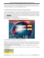
1.3 Examples of applications
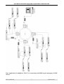
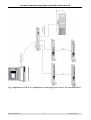
Figures 1, 2 and 3 show the examples of topologies of networks managing the domains of
LANEX devices.
IOA-LANWIN-1H
2
February 2006
SOFTWARE FOR MONITORING AND CONFIGURING LANEX DEVICES
USER’S MANUAL
Fig.1 Application of multiplexer TM-47.1-1 cooperating with SDH ring for managing LANEX
devices
IOA-LANWIN-1H
3
February 2006
SOFTWARE FOR MONITORING AND CONFIGURING LANEX DEVICES
USER’S MANUAL
W AN network
10BASE - T
Management station
Hub
10BASE - T
10BASE - T
IP 10.1.0.1
RS - 232
DCE
2 . RXD
3. TXD
5. SG
ZA SILA NIE
TM - 4 7 .1 -1
M U LTIP LE KSE R 8 xR S - 2 3 2 / ET H E RN ET 1 0 B AS E - T
TM-47.1-1
. .
. .
TERM INAL
IP 10.1.0.2
10 B A S E - T
ZA SILA NI E
M ID I-X
RC V
LINK
TM -4 7 .1- 1
M U LTIP LE KSE R 8 xR S - 2 3 2 / E TH E RN ET 1 0 B A SE - T
TM-47.1-1
8 x RS 232
. . . . .
RS - 2 32
DCE
2 . R XD
3. TXD
5. SG
TER MI NAL
1 0B A SE - T
M ID I- X
RC V
LINK
8 x RS 232
Other devices
TM44/ TM 49/ TM 60/ TM61/ TM71
MODEM O W IA TLOW ODOW Y
E3/G.703
TM -61
TM-61
TM -60
TM-71
.
.
.
.
TM-72
.
. . . . .
TM-60
TM -60
Other devices
Fig. 2 Application of TM-47.1-1 multiplexer for managing Lanex devices via WAN
IOA-LANWIN-1H
4
February 2006
SOFTWARE FOR MONITORING AND CONFIGURING LANEX DEVICES
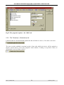
Management station
USER’S MANUAL
Fig.3 Application of TM-47.1-1 multiplexer for managing Lanex devices via serial link RS232
IOA-LANWIN-1H
5
February 2006
SOFTWARE FOR MONITORING AND CONFIGURING LANEX DEVICES
USER’S MANUAL
1.4 Installation and first run
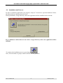
In order to install the application, run program “setup.exe” located on a provided medium. Follow
the hints which are displayed on the screen.
During installation, a target directory where the application will be installed can be selected.
Fig. 4 Window in which the user can select a target directory where the application will be
installed
.
To continue the installation process, press button
Next, select the name of group to which software will be qualified.
IOA-LANWIN-1H
6
February 2006
SOFTWARE FOR MONITORING AND CONFIGURING LANEX DEVICES
USER’S MANUAL
Fig.5. Window in which the user can select LANwin application affiliation to a selected group
of programs
After selecting a target directory and group name, files are copied to a selected directory and
components are registered in a system register. During installation, copied files may be news than
the files used in the system and it may be necessary to restart the computer. In such a case, after
loading the operating system to the memory, repeat the installation process.
Fig.6. Window in which the user is informed on the course of installation process
IOA-LANWIN-1H
7
February 2006
SOFTWARE FOR MONITORING AND CONFIGURING LANEX DEVICES
USER’S MANUAL
Fig.7. Window in which the user is informed on the result of installation process
After installing the software in a directory selected by the user, in the system menu, the group consisting of a shortcut to the execution file and to help files is added. After the first run of the application, the shortcut to the executable program will be created on the system desktop.
The program’s main window will be displayed on the screen.
Fig.8. The application’s main window after its first run
IOA-LANWIN-1H
8
February 2006
SOFTWARE FOR MONITORING AND CONFIGURING LANEX DEVICES
USER’S MANUAL
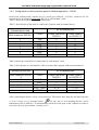
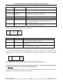
1.4.1 Configuration of communication ports for LANwin application - LOCAL
In the local working mode, with the use of a serial port (LANwin – LOCAL), connect to PC an
external device by means of plain cable RS-232 or “null modem” cable.
Table 1 shows the required list of cable connections.
Table 1. Specification of the cable to connect the computer with an external device
PC or terminal end
External device end
Male connector DSUB-9
2
3
7
8
4
6
5
Circuit
TxD
RxD
RTS
CTS
DTR
DSR
SGND
Female connector
DSUB-9
2
3
7
8
4
6
5
Female connector DSUB-25
3
2
4
5
20
6
7
Table 2 shows the required list of connections of “null modem” cable.
Table 2. Specification of “null modem” cable to connect the computer with an external device
PC or terminal end
External device end
Male connector DSUB9
2
3
5
Circuit
TxD
RxD
RTS – CTS
DTR – DSR
SGND
Female connector
DSUB-9
2
3
7–8
4–6
5
Female connector DSUB-25
3
2
4–5
6 – 20
7
After connecting the device, select a free serial port. This can be done from the sub-menu Options
⇒ Port settings or by pressing button
. In the case of free-standing devices, select
transmission rate of 9600 bps. To automatically search all serial ports in the computer in order to
seek active devices, press button “autodetection”.
IOA-LANWIN-1H
9
February 2006
SOFTWARE FOR MONITORING AND CONFIGURING LANEX DEVICES
USER’S MANUAL
Fig. 9. Window for setting serial port’s settings
After establishing a correct connection, in the window of active devices, the connected device
should be automatically detected.
Fig.10. Window in which detected devices are displayed
IOA-LANWIN-1H
10
February 2006
SOFTWARE FOR MONITORING AND CONFIGURING LANEX DEVICES
USER’S MANUAL
Additionally, to accelarate the search process, press button
.
If you click on a selected device, the window associated with a given type of device will open.
To initialise the system, press button
and the search process will begin again.
, and all windows of the devices will be closed
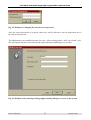
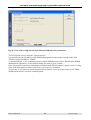
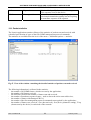
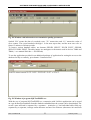
1.4.2 Configuration of communication ports for LANwin application - NET
If the program works in a network mode via a wide area netowork with the use of TCP/IP protocol,
enter IP addresses of multiplexers TM-47 and provide affiliation to a region.
To do this, press button
. The window displays information on a selected IP address, connection
status, name granted by a user and selected region.
Fig.11. Window for configuring parameters of connection via IP network
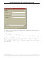
With the use of the configuration window, new connections can be added (button "Add" ) or deleted
(button "Delete" ).
Fig.12. Window for adding a new connection
IOA-LANWIN-1H
11
February 2006
SOFTWARE FOR MONITORING AND CONFIGURING LANEX DEVICES
USER’S MANUAL
In field "IP address", enter the address of TM-47 multiplexer or remote computer, in field "name",
enter any name identifying a given device.
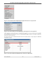
The set configuration can be saved to a file. To do this, open the context menu (by clicking the
mouse’s right button within a main box).
Fig.13. The method of configuration saving to or reading from a file
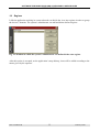
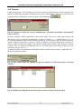
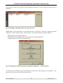
1.5 Access codes
The LANwin (NET) network application requires access codes to be entered. This option is
available from the main menu.
For the LANwin application operating in the network mode using the TCP/IP protocol, support of
all LANEX hardware is enabled. Only the maximum number of detected devices is limited. The
updated status is displayed in the right part of the window. The access code is printed on the cover
of the supplied CD.
IOA-LANWIN-1H
12
February 2006
SOFTWARE FOR MONITORING AND CONFIGURING LANEX DEVICES
USER’S MANUAL
Fig.14. Window of LANwin application working in a local mode where the user can enter access codes
When you enter the access code and press the Add button, the maximum number of supported
devices will be updated.
The application does not inform you that more devices that can be processed by the program
are connected to the managing station.
IOA-LANWIN-1H
13
February 2006
SOFTWARE FOR MONITORING AND CONFIGURING LANEX DEVICES
USER’S MANUAL
2 Basic program’s functions
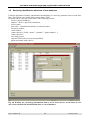
2.1 Options of application’s main window
2.1.1 The “List” tab
The application’s main window includes two tabs. In the first tab, the list of all connected
devices is displayed.
Fig.15. The program’s main window displaying the list of devices
In column "type", the device’s type and icon symbolizing its status (⇒ “Description of
graphic symbols”) are displayed. Column "name" includes a name which the user can
change, at his/her discretion, in order to easily identify a selected device. In column "address", a four-byte address unequivocally identifying each device in the network is displayed.
Column “status” specifies the location of a selected device in the network with respect to the
managing station. In the case of devices installed in a rack, column "slot number " includes
information on the adapter’s location in a rack. In the case of devices equipped with the
IOA-LANWIN-1H
14
February 2006
SOFTWARE FOR MONITORING AND CONFIGURING LANEX DEVICES
USER’S MANUAL
working mode switch – “Software/hardware configuration”, in column "configuration”, current method of adapter’s configuration is displayed.
In the case of the application working in a network mode, the following columns can also be
displayed:
-
IP address – the device’s affiliation to IP address of TM-47 multiplexer;
Region - TM-47 – the region (geographical area) defined by the system’s administrator to
which TM-47 multiplexer has been atributed;
Port no – the number of RS232 port of TM-47 multiplexer to which the device is
connected.
The elements displayed in the “List” tab can be selected, at the user’s discretion, from the
program’s options sub-menu (⇒ “Program’s configuration”).
The working status of devices is signalled by a proper colour of an icon (⇒ “Description of
graphic symbols”). Additionally, by clicking the mouse’s right button, the user can dropdown the context menu to check the device’s working status. All information on alerts occurring in all devices is additionally saved to file alarmy.txt (global file) in sub-directory
“Alarm”, in the directory where the application has been installed. In files alarmy_xx.txt
(files associated with individual devices), where xx is the device’s physical address, reports
related to only the device of a given address are recorded.
Fig.16. Window including basic information on the device
Sending information on alerts to external systems, sending SMSes, TRAP SNMP, and
saving to text files in “Alarm” directory takes place only after information on all devices
in the system is gathered. The progress bar located in the program’s main window
informs on the duration of data downloading. The duration of data gathering depends
on the number of devices detected in the system.
IOA-LANWIN-1H
15
February 2006
SOFTWARE FOR MONITORING AND CONFIGURING LANEX DEVICES
USER’S MANUAL
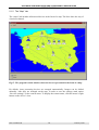
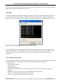
2.1.2 The “Map” tab
The “mapa” tab includes all detected devices in the form of a map. The lines show the way of
a business channel.
Fig.17. The program’s main window where devices are presented in the form of a map
By default, icons presenting devices are arranged automatically. Images can be shifted
manually. After they are arranged on the map, in order to save the settings, mark option
“Save the settings” on the context menu. To display the context menu, click the mouse’s right
button on the device’s icon.
IOA-LANWIN-1H
16
February 2006
SOFTWARE FOR MONITORING AND CONFIGURING LANEX DEVICES
USER’S MANUAL
From this point you can check the working status of a selected device by selecting option
“Properties”.
The size of displayed icons can be changed. Three sizes are accessible; namely, small,
medium and large.
2.1.3 Logical maps
With the use of the software, you can create logical maps which are freely defined and associated with the account of the logged user. To open the window with logical maps, press butin the bar. After pressing the button, the following box will open:
ton
IOA-LANWIN-1H
17
February 2006
SOFTWARE FOR MONITORING AND CONFIGURING LANEX DEVICES
USER’S MANUAL
Three following elements are accessible in this box:
Adding a new tab with the user’s map
Deleting the tab with the map created by the user
Changing the name of the tab with the map
Deleting an object from the map
To add an element in the map, use the drag and drop method and simultaneously press
button CTRL or ALT. By selecting an object in which you are interested and which is included on the devices’ list or located on a selected physical map of devices, by means of the
dragging method, the object can be added to a selected tab with network’s logical map.
2.1.4 Macro-commands
The software includes the added possibility of recording and reading macrocommands registered by the user. In this way, the configuration progress of a selected device’s type can be
and to read, press button
. If you press the
automatised. To record macro, press button
button for recording macrocommands, all information sent to the device (if the current user
has the rights to save) will be registered in file “tmx.mac”, where x is the device’s type. For
example, in the case of TM60 multiplexer, macro file name will be “tm60.mac”.
Macro files are associated with a device’s type not with a specific device.
IOA-LANWIN-1H
18
February 2006
SOFTWARE FOR MONITORING AND CONFIGURING LANEX DEVICES
USER’S MANUAL
2.1.5 Archiving of maps
In the application, existing graphic maps can be saved and read. To save the map, press button
, to read the saved configuration, press button
.
In the software, two types of files are created depending on a version. In the case of a network version (net), network topology is saved in file “klient.urz”, in the case of application
working in a local mode (local) – in file “normal.urz”.
2.2 Program’s configuration
2.2.1 The “Program” tab
With the use of the application, the following parameters can be configured:
-
Automatically open the window of active devices. If this option is marked, after the device is
detected in the network, the window of a detected device will open automatically.
-
Require confirmation when exiting the program. If this option is marked, each time the
application is closed, the message demanding confirmation will be displayed.
-
Hide column descriptions in the device list. After marking and accepting this option,
information in the column headers of the program’s main window such as type, name, address,
status etc. will be hidden.
-
Mark the whole line in the devices’ list. If this option is marked, in the program’s main window,
for a selected device, the whole line will be highlighted.
-
Show progress bar when updating parameters. Updating parameters in the device lasts several
seconds. If this option is marked, during saving the values provided by the user, the progress bar
informing on the saving process will be displayed.
-
Maximal number of open windows. The user can set the maximal number of windows which
will be displayed in the application. If the next window is opened, the older opened window will
be automatically closed or a message will be displayed, depending on the option selected by the
user.
In device TM-44, TM-60 and TM-61, alerts can be confirmed remotely (equivalence of pressing
button ALACK located on the device’s front panel). To do this, it is necessary:
- to have a correctly configured e-mail box (email) and installed Microsoft e-mail client (e.g.
Outlook Express);
- to have permanent access to the Internet;
- to enter, in the e-mail subject, the physical address or name of the device in which we want to
confirm the alert;
IOA-LANWIN-1H
19
February 2006
SOFTWARE FOR MONITORING AND CONFIGURING LANEX DEVICES
USER’S MANUAL
-
to include word “ack” (Acknowledge) in the mail message.
The user can set the e-mail box checking interval. If option “Option active” is marked, new
messages will be checked automatically according to a set interval.
Fig.18. The program’s options – the “Program” tab
2.2.2 The “Rack” tab
In the RACK tab, the following check boxes are accesible:
-
“Delay in reporting by devices” establishes a time window of a single adapter in a rack. By
default, the parameter value is 30 ms. If all the adapters in the system are not detected, the value
can be increased only at the cost of shortening the time of adapter’s refreshing parameters;
-
“Interval of detecting devices in the network” specifies the frequency of automatic searching of
new adapters in the network;
-
“Time period after which the device is deemed as inactive” means the number of unconfirmed
packages sent to a given adapter. The parameter’s value should be selected empirically,
depending on the number of installed adapters. Default value of 15 is recommended;
IOA-LANWIN-1H
20
February 2006
SOFTWARE FOR MONITORING AND CONFIGURING LANEX DEVICES
USER’S MANUAL
-
“Interval of checking adapter’s parameteres” specifies the time intervals in which the
application will send queries to adapters;
-
if option “close the adapter’s window by doubleclicking” is marked, the window of adapter
MD71 can be closed by doubleclicking any graphic element;
Fig.19. The program’s options – the “Rack” tab
2.2.3 The “View” tab
By means of the application, information displayed in the main window can be configured. The user
can display or hide such elements as: device name and physical address, status (local or remote
device), slot no. (for rack devices), configuration (software or hardware configuration for devices
equipped with such an option), and vendor’s number granted during manufacturing.
IOA-LANWIN-1H
21
February 2006
SOFTWARE FOR MONITORING AND CONFIGURING LANEX DEVICES
USER’S MANUAL
Fig.20. The program’s options – the “View” tab
2.2.4 The “Shortcuts” tab
From active program, shortcuts can be created on a system desktop. The user can create the shortcut
to:
- Application working in a basic mode (with the use of serial interface RS-232);
- Application working in a demonstration mode. In this mode, the user can watch the devices’
windows and the device does not have to be physically connected.
Fig.21. The program’s options– the “Shortcuts” tab
IOA-LANWIN-1H
22
February 2006
SOFTWARE FOR MONITORING AND CONFIGURING LANEX DEVICES
USER’S MANUAL
2.2.5 The “SMS” tab
In LANwin application, if a failure is detected in a device, a text message can be sent to cellular
phones. Subscribers have to activate the service of receiving SMSes from the Internet gates.
In field “SMS gate”, enter the name in the following form “@xxx.xxx.x”. The list of current and
operational gates can be downloaded from the Internet.
In field “phone no or account name”, enter phone number in the following form: 48yyyxxxxxx. In
this place, you can also enter the name of mail account; in such a case, messages will be sent not to
a cellular phone but to a selected e-mail box.
The user can configure the text of sent information. Such information can include the device’s type
and name, physical address, date and time of alert occurrence, and alert type and its description.
To check if performed entries and sent text message are correct, press button
IOA-LANWIN-1H
23
.
February 2006
SOFTWARE FOR MONITORING AND CONFIGURING LANEX DEVICES
USER’S MANUAL
Fig.22. The program’s options – the “SMS” tab
2.2.6 The “Parametry” {Parameters} tab
LANwin software can automatically update the date and time in a device, if its value is incorrect.
The user can also establish a maximal period of time after which the device will be marked as
inactive on the devices’ list in the program’s main window, if during a set period of time, no
information is received from a device.
IOA-LANWIN-1H
24
February 2006
SOFTWARE FOR MONITORING AND CONFIGURING LANEX DEVICES
USER’S MANUAL
Fig. 23. The program’s options – the “Parametry” tab
To urgent and non-urgent alerts you can attribute a sound file which will be generated each time an
alert in the system is detected. To select a sound file, press button
, and to listen to a selected
file, press button
.
IOA-LANWIN-1H
25
February 2006
SOFTWARE FOR MONITORING AND CONFIGURING LANEX DEVICES
USER’S MANUAL
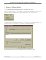
3 Program’s additional options
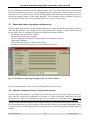
3.1 Protecting the program by a password and adding new users
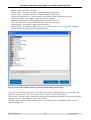
After the program is installed, it works with full access rights in the administrator’s mode. The administrator can protect the application by a password. This can be done in the main menu:
The window includes information on current users. With the use of the configuration window, you
can add or delete a user, check the user’s access rights, and change the password.
Fig. 24. Window in which the system’s administrator can grant rights to users
IOA-LANWIN-1H
26
February 2006
SOFTWARE FOR MONITORING AND CONFIGURING LANEX DEVICES
USER’S MANUAL
Fig. 25. Window for changing the current access password
After the selected password is accepted, other users will be allowed to run the application only if
they know the password.
The administrator can establish accounts for users. After pressing button “Add”, the wizard’s window will appear and the wizard will provide support during establishing a new account.
Fig. 26. Window of the wizard providing support during adding a new user to the system
IOA-LANWIN-1H
27
February 2006
SOFTWARE FOR MONITORING AND CONFIGURING LANEX DEVICES
USER’S MANUAL
IOA-LANWIN-1H
28
February 2006
SOFTWARE FOR MONITORING AND CONFIGURING LANEX DEVICES
USER’S MANUAL
IOA-LANWIN-1H
29
February 2006
SOFTWARE FOR MONITORING AND CONFIGURING LANEX DEVICES
USER’S MANUAL
During a normal work, the administrator can change the parameters of a selected account.
Fig. 27. Window by which the administrator can change the rights of individual users
IOA-LANWIN-1H
30
February 2006
SOFTWARE FOR MONITORING AND CONFIGURING LANEX DEVICES
USER’S MANUAL
With the use of “properties” , the administrator can establish the location of raport’s file (log),
where information on running and closing application and unauthorised attempts to enter the system
will be recorded.
Fig. 28. The window “Properties” by which the system’s administrator can change the location of the raport’s file
3.2 Security device access password
Device access security against unauthorized users has been added starting from the software version
3.01 on. In order to gain access to a given device access password assigned by the
operator is necessary . Default password is inactive.
The older versions of the Lanwin software allow only for the reading of device parameters,
however, changing their configuration is not possible.
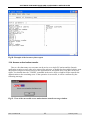
Assigning an access password or a change (or its removal) is available in the context menu in the
device list window.
IOA-LANWIN-1H
31
February 2006
SOFTWARE FOR MONITORING AND CONFIGURING LANEX DEVICES
USER’S MANUAL
Fig.29. Context menu used for displaying the input of the device access password
Fig.30. View of the window used for inputting or removing device access password.
After inputting a password the user is automatically logged out. Access to the device is possible
after inputting access password. The user is automatically logged out after 10 seconds of inactivity
on the level of a given device.
The login status may be checked from the device list context menu or map using the “additional
information” option.
Fig.31. View of the window informing the user of the device login status
IOA-LANWIN-1H
32
February 2006
SOFTWARE FOR MONITORING AND CONFIGURING LANEX DEVICES
USER’S MANUAL
3.3 Regions
LANwin application working in a network mode can divide the view into regions in order to group
the devices’ domains. The system’s administrator can add and delete defined regions.
Fig. 32. Window in which the system’s administrator can define his/her own regions
After this option is accepted, on the application’s map desktop, icons will be added according to the
names given by the operator.
IOA-LANWIN-1H
33
February 2006
SOFTWARE FOR MONITORING AND CONFIGURING LANEX DEVICES
USER’S MANUAL
Fig. 33. Window with the regions defined by the operator
When TM-47 multiplexers are added to the system, they should be allocated to one of defined
regions. This can be done also when the application is operating.
Fig. 34. Allocating TM-47 multiplexer to a region
Each device appearing in the system should be allocated to an actual region. (⇒ chapter
“Identification data”)
IOA-LANWIN-1H
34
February 2006
SOFTWARE FOR MONITORING AND CONFIGURING LANEX DEVICES
USER’S MANUAL
When the administrator creates the users’ profiles, he/she can choose regions and devices’ groups
which a selected user can access.
Fig. 35. Defining regions to which a user has access
3.4 Identification data
To each device, additional identification data gathered in a local database can be allocated. They
include:
Field
“Address”
“Contact person 1”
“Accessing person”
„Inventory no”
Description
Device localisation
Name
Surname
Stationary phone no
Cellular phone no
Name
Surname
Stationary phone no
Cellular phone no
Cellular phone no
Number given by an operator
“Serial no”
Number given by an operator
“Region”
Device’s association with a selected region in the country
“Photos” (files’ names)
Room’s diagram
General view
Other view
“Contact person 2”
IOA-LANWIN-1H
35
February 2006
SOFTWARE FOR MONITORING AND CONFIGURING LANEX DEVICES
USER’S MANUAL
Fig. 36. Window including identification data of a selected device
To walk between consecutive devices from a list, press buttons
.
For fields “region” and “photo” , you can press additional buttons to select elements from a disk
(photo) or a list (regions) for authorised users.
Fig. 37. Window for selecting graphics files
To display the window including the contents of a graphics file located in the application’s
directory in sub-directory “Graph\”, press buttons
The object can be displayed in
the scale of 1:1 or its size can be adjusted to the window’s size (option “Scale”).
IOA-LANWIN-1H
36
February 2006
SOFTWARE FOR MONITORING AND CONFIGURING LANEX DEVICES
USER’S MANUAL
Fig. 38. Window including the user’s graphics file
3.5 Port identification
The operator can assign to each port an identification number and name of a customer using a current channel. This option is accessible from the context menu “Port name”.
Fig. 39. Window with the information on device’s data transmission port
To quickly walk between devices located on the list, press buttons
. A channel leased to a
selected customer can be easily identified by means of an identification number and customer name.
IOA-LANWIN-1H
37
February 2006
SOFTWARE FOR MONITORING AND CONFIGURING LANEX DEVICES
USER’S MANUAL
3.6 Retrieving identification data from a local database
LANwin application includes implemented mechanisms for retrieving elements from a local database. This option is accessible from context menu “Find”.
Elements can be retrieved on the basis of the following criteria:
- device’s physical address;
- address – device’s physical localisation;
- device name;
- port name – identification number or customer name;
- inventory number;
- serial number;
- contact person 1 (fields: “name”, “surname”, “phone number” );
- contact person 2;
- accessing person;
- region to which a device has been qualified;
- photo associated with a device.
Fig. 40. Window for retrievieng information from a set of active devices on the basis of various criteria included in identification data of a local database
IOA-LANWIN-1H
38
February 2006
SOFTWARE FOR MONITORING AND CONFIGURING LANEX DEVICES
USER’S MANUAL
Devices fulfilling retrieval criteria are displayed on the list. If you click on the device located on the
list of found elements, the device will be highlighted in the application’s main window. From this
point, the device on the map can be found and the window associated with a selected device can be
opened. By marking option “In the whole database”, a local database can be searched on the basis
of a selected criterion irrespective of whether the device is active in the system.
3.7 Export and import of program configurations
LANwin application includes an implemented function of export and import of program configurations. By this function, user settings can be easily transferred to another computer and the system
does not have to be re-configured. Exported and imported elements include:
- all graphics files in directory \Graph\;
- all sound files in directory \Sound\;
- all files of reports about alerts occurring in devices in directory \Alarm\;
- application’s database;
- information on locations of objects on the maps;
- all entries to the system register associated with the application;
Fig. 41. Window for exporting configurations of LANwin software
Option of export/import can be accessed in the application’s main menu.
3.8 Interface of export of alerts to an external system
LANwin application listens to, on TCP/IP port selected by the user, the queries from external systems. After the connection is established, in real time, i.e. after receiving the TRAP order from connected devices, orders are transmitted in the form of packages on a configured port. Data on detected alerts are sent to an external system after the data from connected devices are completed. The
duration of this operation depends on the number of devices introduced to the system. The progress
bar located under the list in the program’s main window informs on the data downloading status.
For the purposes of communication with an external system, the following data exchange format is
applied:
IOA-LANWIN-1H
39
February 2006
SOFTWARE FOR MONITORING AND CONFIGURING LANEX DEVICES
USER’S MANUAL
Start flag
Type
Address
Date
Alert type
Alerts
...
Field
Start flag
Type
Address
Date
Alert type
Alerts
End flag
End flag
...
Value
E.g. ~ [0x7E]
Description
Character starting the sequence related to one device, start
flag value will be defined by the user
TM60, TM44 Type of device from which information on alert is received
E.g. 20709377 Physical address unequivocally identifying a device in the
network
2001-10-05
Date and time of alert occurrence
13:22.07
UAL, NUAL, UAL – urgent alert;
UL, TE, BA
NUAL – non-urgent alert;
UL – loss of communication with a device;
TE – informs on activation of a pseudo-random sequence
generator or activity of test loops;
BA – no alerts or have been confirmed by the operator.
LOSS, LOF, LOSS – loss of optical signal;
E103, E106,
LOF – loss of frame synchronisation;
LDF, RAL,
E103 – exceeding error rate E-10-3;
E106 – exceeding error rate E-10-6;
ZSS1 –
ZSS16
LDF – transmitter power fading;
RAL – alert to a remote device;
ZSS1-16 – component signal fading 1 – 16.
E.g. [0x7F]
Character ending a sequence, value defined by the user. It
has to differ from the start flag
Individual fields are separated by separators defined by the user e.g. „;”
Separator’s value, and start and end flag cannot appear in the data field.
Start flag, end flag, separator, and port number can be defined by the system’s administrator. This is
accessible in the program’s main configuration in the “Program” tab under button
Fig. 42. Window for working configuration of interface to an external system
IOA-LANWIN-1H
40
February 2006
SOFTWARE FOR MONITORING AND CONFIGURING LANEX DEVICES
USER’S MANUAL
3.9 Interface of export of data on hardware configuration to an external system
LANwin software waits for establishing a connection via the network with the use of TCP/IP protocol on a port selected by the operator. After the connection is established, the application sends information only after it receives a demand from an external system. After the demand is received, the
application sends the information about addresses of all devices in the network or information about
the devices selected by the operator.
The format of responses returned by LANwin application:
Start
flag
Type
...
Address
Accessing person
Name
Vendor’s
no
Node
no.
Inventory number
Field
Start flag
Value
E.g. ~ [0x7E]
Type
TM60, TM44
Address
E.g. 20709377
Name
Vendor’s no
Node no
TM-60_LUBLIN_2
E.g. 1234
1,2,3 etc.
Channels’ activity
E.g. 65280
Port ID
Customer
000123
Kowalski
Address
Diamentowa 2
Data of person Stanisław;
1
Nowak;123456;0607
123456
Data of person Stanisław;
2
Nowak;123456;0607
123456
IOA-LANWIN-1H
Channel
activity
Names of diagram files
with photos
...
Port’s
ID
Region
Customer
...
Serial number
Address
Data on
person 1
Data on
person 2
Previous node
End flag
Description
Character starting the sequence related to one device, start
flag value will be defined by the user
Type of device from which information on configuration
is received
Physical address unequivocally identifying a device in the
network
Device name given by the user
Number given during production – read-only value
On the basis of the field, the device’s location in the network with respect to the managing station can be identified; 1- local device, 2- remote device etc.
Number converted in the form of a character string informing on the activity of component channels in the device – in this case, channels 16 to 9 are on and channels 8
to 1 are off.
Number attributed to port G.703 of device TM44 or TM60
Customer using a selected channel.
Field “port ID” and “customer” will appear depending on
the device type: for TM44 – 4, for TM60-16 (number of
accessible ports)
Device’s localisation
Name, surname, stationary phone number, cellular phone
number of person 1
Data separated by separators
Name, surname, stationary phone number, cellular phone
number of person 1
Data separated by separators
41
February 2006
...
SOFTWARE FOR MONITORING AND CONFIGURING LANEX DEVICES
USER’S MANUAL
Accessing person
Inventory
number
Names of diagram files with
photos
Region
Serial number
Previous node
End flag
0607123456
Accessing person’s cellular phone no
121212
Inventory number given by the operator
Bitmapa1, bitmapa2,
bitmapa3
Room diagram, general view, other view – names of
graphics files separated by separators
Lublin
1234
20709378
Region to which the device is attributed
Serial number given by the system’s administrator
Physical address of previous device in the network. On the
basis of this information, network topology can be unequivocally specified.
Character ending the sequence, value defined by the user.
It has to differ from the start flag
E.g. [0x7F]
Format of a query generated by an external system:
Start
flag
Address
End
flag
Field
Start flag
Value
E.g. ~ [0x7E]
Address
E.g. 20709377
End flag
E.g. [0x7F]
Description
Character starting the sequence related to one device, start
flag value will be defined by the user
Physical address unequivocally identifying a device in the
network *)
Character ending the sequence, value defined by the user. It
has to differ from the start flag
*) – If non-zero value is entered in field “address” , the response related only to a selected device
will be generated. If the device of a set address does not exist, the response of the following format
is sent:
Start
flag
0
End
flag
Individual fields will be separated by separators defined by the user e.g. „;”
If, in the query sent by an external system, in field “address” }, value 0 is entered, information
on addresses of all devices in the system will be returned.
To preview the status of connection of external systems using the application, press the mouse’s
right button on the status bar of network connection.
IOA-LANWIN-1H
42
February 2006
SOFTWARE FOR MONITORING AND CONFIGURING LANEX DEVICES
USER’S MANUAL
Fig. 43. The context menu for opening the preview window of the status of connection with
external systems
Fig. 44. Window in which the status of connection with external systems can be checked
3.10 TRAP SNMP
The Lanwin application v.2.70 has been enriched by a module generating TRAP SNMP
version 1 commands to external systems supporting this protocol. As the default setting, the alarm
option is inactive. You can access the interface parameters from the level of global program options
-> "TRAP SNMP" tab.
IOA-LANWIN-1H
43
February 2006
SOFTWARE FOR MONITORING AND CONFIGURING LANEX DEVICES
USER’S MANUAL
Fig.45. View of the set-up window with TRAP-SNMP interface parameters
You activate the service using the "Option activity".
You should enter the IP address of the SNMP administrator located in the network in the field
"TRAP recipient IP address" SNMP.
"CommunityName" is the community name by which SNMP packets will be filtered in the SNMP
administrator application. As the default setting, the name is set to "public".
If the "Descriptive form of the information contained in the TRAP contents" option is active, a long
form of the description of alarm events from a given device is attached.
You use the "Test" button to test the program set-up options. If you press the button, a test TRAP
SNMP packet will be sent to an external system.
IOA-LANWIN-1H
44
February 2006
SOFTWARE FOR MONITORING AND CONFIGURING LANEX DEVICES
USER’S MANUAL
Fig.46. Format of the TRAP commands generated by the Lanwin application
The following information is contained in the TRAP command descriptive field:
- type of device, e.g. TM-79;
- unique device address assigned during production;
- short or long information on the device event type (Table 3);
- name of device, e.g. TM-79.1;
The available information in the long and short forms is presented in Table 3.
Table 3. Interpretation of the short and long form of information contained in the TRAP command
contents
Short information Long information
UL
Loss of
communication
BA
No alarms
NL
TE
IOA-LANWIN-1H
Communication
established
Tests
Description
Loss of communication with a device
A device is active and no alarm criteria exist in
the device or they have been confirmed by
the operator
Connection with a device has been restored
Device tests are in progress (internal PRBS
generator is on or at least one test loop is active)
45
February 2006
SOFTWARE FOR MONITORING AND CONFIGURING LANEX DEVICES
USER’S MANUAL
UAL
Urgent alarm
NUAL
Non-urgent alarm
Criteria which qualify for an immediate response
of the operator occur in the device.
A device has detected criteria proving e.g.
deteriorated transmission quality but not requiring
an immediate response of the operator
3.11 Packet statistics
The Lanwin application contains a library of the statistics of packets sent and received with
a detailed specification of types of the firm LNMP management protocol commands.
The statistics are available from the level of the menu -> additional options -> statistics.
Fig.47. View of the window containing the detailed statistics of packets sent and received
The following information is collected in the statistics:
- the number of all LNMP frames, which were sent by the application;
- the number of all frames received;
- the difference between the number of frames sent and received;
- the number of broadcast-response frames – used to detect the active network devices;
- the number of frames with damaged CRC16;
- the number of the firm management protocol commands unrecognised by the application ;
- the number of frames sent, received, -Get (data retrieval), -Set (device parameter setting), -Trap
(alarms sent by the device) in each node of the network.
IOA-LANWIN-1H
46
February 2006
SOFTWARE FOR MONITORING AND CONFIGURING LANEX DEVICES
USER’S MANUAL
The data is collected in the program from the moment the application is activated. If you switch the
program on and off, the counters are set to zero.
3.12 Ping
The Lanwin application contains a module to test the connection to a selected node on the network an equivalent of the system "ping" command. The option is available by clicking the right mouse
button on the selected network element and by selecting the "Properties" option and the "ping" tab.
Fig.48. View of the communication testing module window
You use the "Ping" button to start the communication testing procedure and to test response time
from a selected device. 10 commands are sent to a device. When the procedure is finished, a report
regarding response time, quantities of packets received and average device response time is
generated.
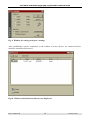
3.13 Inventory data report
The managing application is equipped with a module to generate a report containing the information
regarding the device inventory data. The report contains the following information:
- type of device;
- device physical address;
- name of device;
- manufacturing number;
- node number (device location on the managed device network in relation to the managing
station);
- channel activity (refers to devices, in which channels can be disabled);
- port ID – the number assigned to device port (ports);
- client – name of the client using a given device port;
IOA-LANWIN-1H
47
February 2006
SOFTWARE FOR MONITORING AND CONFIGURING LANEX DEVICES
USER’S MANUAL
-
address – physical device location;
person 1 data – forename, surname, telephone number of person 1;
person 2 data – forename, surname, telephone number of person 2;
person performing access – phone number of the person supervising a given device;
inventory number – the number assigned by device operator;
names of diagram files including photographs matched to devices;
area – the name of the area, to which the device has been assigned;
serial number – the number assigned by the operator;
previous node – the physical address of a device, which is the previous node of the managed
device network in relation to the managing station;
Fig.49. View of the windows used to generate the inventory data report
The user can select information to be included in the report. Additionally, the user can filtrate the
report for a given device type. You use the "Device types" field for this purpose.
You use the "Generate report" button to start the report generation procedure. You can view the last
generated report by pressing the "Last report" button.
The input format of the inventory data report is a standard text file. An example of the report is
shown in Figure 47.
IOA-LANWIN-1H
48
February 2006
SOFTWARE FOR MONITORING AND CONFIGURING LANEX DEVICES
USER’S MANUAL
Fig.50. Example of the inventory data report
3.14 Access authorization transfer
Due to a fact that many user accounts can be active on a single PC station and the Lanwin
application requires access codes to be entered for each user, a module has been added, which, upon
an operator's request, activates access to the application for all system users, who have all access
rights. You should enter the "CODES" command in the active device window field to transfer the
authorizations to the remaining users. If the operation is successful, it will be confirmed by the
following message:
Fig.51. View of the successful access authorization transfer message window
IOA-LANWIN-1H
49
February 2006
SOFTWARE FOR MONITORING AND CONFIGURING LANEX DEVICES
USER’S MANUAL
3.15 Terminal
LANwin application - NET working in a network mode can maintain up to 6 remote terminal. The
number of maintained terminal is defined by the system’s administrator. This is accessible from the
program’s main configuration, in the “Program” tab under button
.
Fig. 52. Window in which the system’s administrator can define the number of maintained
remote consoles
In order to launch LANwin application in the console mode, it has to be called with parameter /k.
This can be done by using the command line (⇒ Start ⇒ Launch ⇒ “...\lanwin-klient.exe /k”) or
by creating a shortcut on the system desktop with the use of the system wizard. In order to correctly
connect with the base station, we have to define IP address of LANwin application to which we
want to connect and the port number. The system’s administrator allocates port numbers to remote
consoles. They are addresses starting with 1010 i.e. the first console can connect on port 1010, the
second one on port 1011 etc.
To check the status of connection of individual remote consoles, click the mouse’s right button on
the bar of system port status.
Fig. 53. The context menu for opening the preview window of connection status of external
consoles
Fig. 54. Window in which the connection status of remote consoles can be checked
IOA-LANWIN-1H
50
February 2006
SOFTWARE FOR MONITORING AND CONFIGURING LANEX DEVICES
USER’S MANUAL
In order to correctly connect to the main managing station, the administrator has to create the user’s
profile by granting the user the access rights and the rights to preview all or selected regions. (⇒
“Protecting the program by a password and adding new users”).
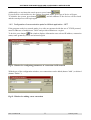
3.16 SQL interface of export of transmission quality parameters
By means of the application you can gather the data on transmission quality of individual interfaces
of devices. Such information is gathered in a local database. Such data can be made accessible to
remote systems. For this purpose, socket TCP in LANwin application is used. By default, this option is inaccessible. On the customer’s request, the application activating this option is provided.
After installing a specially provided package in a directory where LANwin application is installed,
the following two programs are added:
SQL_Activity.exe – to activate the option;
SQLTestESSES.exe – to test added functionality locally or remotely.
Fig. 55. Window of the program activating SQL interface
With the use of program “SQL_Activity.exe” you can switch on or off the interface of export of
quality data to an external system and select the number of TCP port performing the connection. By
default, port number 30000 is selected. After parameters are changed, operation of LANwin application should be shut down and started again.
After activating the option in LANwin application (only net version), additional tabs and menu
commands appear.
On the status bar in the context menu (clicking the mouse’s right button), you can see command
“SQL interface” .
IOA-LANWIN-1H
51
February 2006
SOFTWARE FOR MONITORING AND CONFIGURING LANEX DEVICES
USER’S MANUAL
If this option is chosen, the window with information on the list of users connected to the system is
displayed.
Fig. 56. Window with information on connected users
Additionally, if the information on any detected device in devices’ network is displayed (option
“Properties” in the context menu), “SQL interface” tab with the following options appears:
-
displaying the list of connected users;
browsing the local database where quality data are collected (ES/SES);
testing connection of TCP/IP with the system.
Fig. 57. Window in which the program’s options are gathered – “ SQL interface”
To check the data collected in the local database, press button “Browsing the local database”. The
data relate only to the device indicated by the user.
IOA-LANWIN-1H
52
February 2006
SOFTWARE FOR MONITORING AND CONFIGURING LANEX DEVICES
USER’S MANUAL
Fig. 58. Window with information on transmission quality parameters
Symbol “Dx” means the date of recorded event, “Tx” means time and “Cx” means the value of
error counter. The record marked with digit 1 is the most up-to-date, and the next ones refer to
future 15-minute or 24-hour periods.
To browse various database tables, use buttons SES15R, SES15T, ES15R, ES15T, SES24R,
SES24T, ES24R, ES24T. The table names are analogous to the names used in devices TM60 and
TM44 (-> see manual IO60.doc -> ES/SES tab)
To run the application provided in an additional package of application for testing the access to the
database locally or remotely, press button “Connection test” .
Fig. 59. Window of program SQLTestESSES.exe
With the use of program SQLTestESSES.exe, connection with LANwin application can be tested
on a pre-defined port and data from the database embedded into the system can be downloaded. The
record’s start and end is separated by a separator – semicolon (;), and individual table fields are
separated by a separator; carriage return character and new line character (characters 0xA and 0xD
IOA-LANWIN-1H
53
February 2006
SOFTWARE FOR MONITORING AND CONFIGURING LANEX DEVICES
USER’S MANUAL
ASCII). In the case of an error (incorrect formulation of SQL query), a response with error description is generated. In the information about an error, separator characters are not used.
3.17 Description of graphic symbols
The working status of a connected device is signalled by an icon’s colour:
- device’s normal working status;
- red circle means urgent alert in the device;
- yellow circle means non-urgent alert in the device;
- grey cross means loss of communication with a selected device;
- green circle means actvity of loop or test in the device;
- detection of a device not maintained by the software current version.
In such a situation, check whether the access code for a given device type has been entered correctly
and whether the application’s current version maintaines a given device’s type.
Fig.60. Window with information on devices maintained by the software current version
IOA-LANWIN-1H
54
February 2006
SOFTWARE FOR MONITORING AND CONFIGURING LANEX DEVICES
USER’S MANUAL
3.18 Confirming alerts via electronic mail
In devices TM-44, TM-60 and TM-61, alerts can be confirmed remotely (equivalence of pressing
button PKAL located on the device’s front panel). To do this, it is necessary:
- to have a configured mail box (email) and installed Microsoft mail client (e.g. Outlook Express);
- to have permanent access to the Internet;
- to include, in the e-mail subject, the physical address or name of the device in which the alert is to
be confirmed;
- include, in the e-mail, word “ack” (Acknowledge);
After reading the contents of a selected e-mail box, the alert in an adressed device will be
automatically confirmed.
3.19 Remote configuration of TM-47 multiplexer
LANwin application can remotely configure serial ports of TM-47 device. Access to the option can
be reached from the context menu by clicking the icon showing TM-47 multiplexer.
Fig. 61. The context menu from which the remote configuration window can be called
Each port RS232 of TM-47 multiplexer can work in one of three working modes: LANEX, TERMINAL and TRANSMITTER. To select a mode, select a proper item from check boxes located in
column “Device’s type” on Figure 59.
IOA-LANWIN-1H
55
February 2006
SOFTWARE FOR MONITORING AND CONFIGURING LANEX DEVICES
USER’S MANUAL
Fig. 62. The window of configuration of parameters of channels RS232 of device TM47.1-1
“LANEX” working mode is a basic and default working mode of channel RS232. It is used for
managing LANEX devices. In this mode, the values of ports RS232 settings are default so that the
cooperation with LANEX devices was correct.
Two other working modes; “TERMINAL” and “RELAY”, extend the scope of functions of
LANwin application. Due to the “TERMINAL” mode, other vendors’ devices with the function of
configuration from terminal RS232 can be managed. In the “RELAY” mode, alert connector status
of devices equipped with an alert transmitter can be transmitted. An alert (short-cut of transmitter’s
connectors) is registered and signalled by “LANWIN” application.
In both modes, field “Device’s address” (Fig. 59) should be configured. Such an address is treated
as a hardware address (MAC) granted to all LANEX devices due to which devices managed in the
network can be unequivocally identified. Additionally, such addresses make it possible to automatically recognise the network’s topology by LANwin application. The system will function correctly
only if each managed device has a unique hardware address. In the case of devices, this requirement is fulfilled during the production phase, however, in the case of channels RS232 in TM47
device simulating the presence of managed devices “TERMINAL” and “TRANSMITTER”, the
user has to take care of numbers which are unique in the whole management network by himself/herself (last column in Fig. 59). The address consists of 4 bytes, but for the security purposes,
only a given pool of possible addresses has been allocated, ranging from XXXX0000 to
XXXXFFFF, where XXXX refers to the “TERMINAL” mode equalling 0001, and in the case of
IOA-LANWIN-1H
56
February 2006
SOFTWARE FOR MONITORING AND CONFIGURING LANEX DEVICES
USER’S MANUAL
“TRANSMITTER” mode equalling 0002. In the field “Device’s address” user can enter four characters from the left side. The rest of characters are granted by the configuration program depending
on the working mode.
Moreover, in the “TERMINAL” mode, it is possible to configure the parameters of ports RS232
such as flowability ranging from 2,400 to 57,600 bps (column “Flowability}, Fig. 59), number of
stop bits (column “Stop bits” , Fig. 59) and occurrence and type of parity bit (column “Parity” ,
Fig.59).
The configuration application, upon detecting a device, automatically reads its configuration so that
the program could show the configuration of a given device. After configuration is changed, you
can save it by pressing button “Save and setting” demonstrated on Fig.60.
Fig. 63. Buttons to save device’s configurations and exit the program
After operation “Save configuration” is performed, the whole configuration is saved to the device,
and the fact is confirmed by the window as demonstrated on Fig. 61.
Fig. 64. Window confirming that the operation of saving the configuration to the device has
been completed
{pop-up message}: Configuration has been saved.
For detailed information on TM-47 multiplexer and configuring software, refer to manuals “Multiplexer 8xRS232 / Ethernet 10BaseT” and “Configuring the program for multiplexer 8xRS232
/Ethernet 10BaseT”.
3.20 Troubleshooting
If the computer on which we want to run LANwin application does not have an Outlook Express
mail client installed, problems with port opening may occurr. In such a case, (if, after the
application is run, there are problems with its configuration), launch the program with parameter
/MapiOff. It can be done using the command line or you can create a shortcut on the system
desktop with initial parameter.
IOA-LANWIN-1H
57
February 2006
SOFTWARE FOR MONITORING AND CONFIGURING LANEX DEVICES
USER’S MANUAL
To switch off the welcome screen, run the application with parameter /IntroOff.
To run the program in the demonstration mode, use shortcut /demo.
LANwin application has a defined keyboard shortcut. After pressing shortcut Alt + Z from any
point of the system, the application’s window will be activated.
Sending information on alerts to external systems, sending SMSes and saving to text files in
directory “Alarm” takes place only after information on all devices in the system is gathered.
The progress bar located in the program’s main window informs on the duration of data
downloading. The duration of data gathering depends on the number of devices detected in
the system.
IOA-LANWIN-1H
58
February 2006
SOFTWARE FOR MONITORING AND CONFIGURING LANEX DEVICES
USER’S MANUAL
Made by:
Lanex S.A.
8 Ceramiczna Street
20-150 Lublin POLAND
phone no.: +48 81 444-10-11
fax no.: +48 81 740-35-70
e-mail: [email protected]
web: www.lanex.pl
Contact with the Service:
Phone no. +48 81 4439-639
Lanex S.A. 2006
IOA-LANWIN-1H
59
February 2006