1
LANEX S.A.
8 Ceramiczna Street
20-150 Lublin
POLAND
tel. +48 81444 10 11
tel/fax. +48 81 740 35 70
TM-77, MD-77 MULTIPLEXER
OPERATING MANUAL
LANEX S.A., 8 Ceramiczna Street , 20-150 Lublin
POLAND
IOA77-1G
August 2009
Service: phone +48 81 443 96 39
4XE1/G.703 PLESIOCHRONOUS MULTIPLEXER
OPERATING MANUAL
Table of contents
1
OVERALL CHARACTERISTICS .....................................................................................1
1.1
1.2
1.3
1.4
2
CONNECTORS AND INDICATORS ................................................................................5
2.1
2.2
2.3
3
INTRODUCTION .................................................................................................................5
TM-77 MULTIPLEXER.......................................................................................................5
MD-77 MULTIPLEXER ......................................................................................................7
FUNCTIONAL DESCRIPTION .........................................................................................8
3.1
3.2
3.3
3.4
3.5
3.6
3.7
4
APPLICATION....................................................................................................................1
BASIC FEATURES ..............................................................................................................1
EXAMPLES OF APPLICATION .............................................................................................2
SYMBOLS AND AVAILABLE VERSIONS...............................................................................3
DIAGNOSTIC AND SIGNALING SYSTEMS ............................................................................8
ADDITIONAL CHANNELS ...................................................................................................9
TEST LOOPS ....................................................................................................................10
CLOCK TRANSFER...........................................................................................................10
EVENT LOG .....................................................................................................................11
MONITORED QUALITATIVE .............................................................................................12
MONITORED QUALITATIVE PARAMETERS OF E2 OPTICAL INTERFACE .............................13
INSTALLATION AND OPERATION .............................................................................14
4.1
OPERATING CONDITIONS ................................................................................................14
4.2
INSTALLATION................................................................................................................14
4.3
POWER SUPPLY ...............................................................................................................15
4.4
E1/G.703 LINEAR SIGNAL CONNECTION .........................................................................16
4.4.1
TM-77 and MD-77 ................................................................................................16
4.5
CONNECTION TO VT100 TERMINAL OR COMPUTER WITH INSTALLED LANWIN
MANAGEMENT SOFTWARE ..........................................................................................................17
4.6
FIBER OPTIC LINE CONNECTION ......................................................................................18
5
OPERATION WITH VT100 TERMINAL.......................................................................20
5.1
APPLICATION..................................................................................................................20
5.2
HARDWARE REQUIREMENTS ...........................................................................................20
5.3
INSTALLATION AND START-UP ........................................................................................21
5.4
BEGINNING THE TERMINAL OPERATION ..........................................................................21
5.5
MAIN MENU....................................................................................................................23
5.5.1
System....................................................................................................................24
5.5.2
Interfaces-selection ...............................................................................................25
5.5.2.1 Interfaces-options ..............................................................................................26
5.5.2.2 Set-up ................................................................................................................27
5.5.2.3 15-minute and 24-hour registers .......................................................................28
5.5.3
Time periods..........................................................................................................29
5.5.4
Event log................................................................................................................30
5.5.5
Monitoring.............................................................................................................31
5.5.6
Loops .....................................................................................................................32
6
DEVICE SET-UP USING LANWIN PROGRAM ..........................................................33
6.1
GLOBAL SET-UP ..............................................................................................................33
IOA77-1G
I
August 2009
4XE1/G.703 PLESIOCHRONOUS MULTIPLEXER
OPERATING MANUAL
6.1.1
Device name ..........................................................................................................34
6.1.2
Setting date and time .............................................................................................34
6.1.3
Additional information ..........................................................................................35
6.2
CHANNEL ACTIVITY .......................................................................................................36
6.3
G.826 STATISTICS ..........................................................................................................36
6.3.1
Alarm severity level...............................................................................................38
6.3.2
Alarm thresholds ...................................................................................................39
6.4
TEST LOOPS ....................................................................................................................40
6.5
MONITORING ..................................................................................................................41
6.6
LOG ................................................................................................................................42
6.6.1
Event log................................................................................................................42
6.6.2
Event log filter.......................................................................................................42
7
TECHNICAL SPECIFICATION......................................................................................44
7.7
ELECTRICAL CHARACTERISTICS OF E1/G.703 INTERFACE ..............................................44
7.2
OPTICAL INTERFACE CHARACTERISTICS .........................................................................44
7.3
MECHANICAL PARAMETERS ...........................................................................................46
7.4
ENVIRONMENTAL REQUIREMENTS ..................................................................................46
7.4.1
Operation ..............................................................................................................46
7.4.2
Transport...............................................................................................................46
7.4.3
Storage ..................................................................................................................47
7.5
ELECTROMAGNETIC COMPATIBILITY ..............................................................................47
7.6
POWER SUPPLY ...............................................................................................................47
8
COMPLETE PRODUCT ...................................................................................................48
IOA77-1G
II
August 2009
4XE1/G.703 PLESIOCHRONOUS MULTIPLEXER
OPERATING MANUAL
List of figures
FIGURE 1.
FIGURE 2.
TM-77.1 MULTIPLEXERS USED IN TELEPHONE NETWORKS .......................................2
MD-77 MULTIPLEXERS USED TO CONNECT TELEPHONE SWITCHES AND COMPUTER
NETWORKS USING SDH NETWORK ...........................................................................................2
FIGURE 3.
VIEW AND DESCRIPTION OF TM-77 FRONT PANEL ....................................................5
FIGURE 4.
VIEW AND DESCRIPTION OF DEVICE REAR PANEL......................................................6
FIGURE 5.
VIEW OF TM-77.1 FRONT AND REAR PANELS ...........................................................7
LOOPS ....................................................................................................................10
FIGURE 6.
FIGURE 7.
DEVICE INSTALLATION IN FORM OF MD-72 TELECOMMUNICATION RACK CARD,
FRONT VIEW. ..........................................................................................................................14
FIGURE 8.
DEVICE INSTALLATION IN FORM OF MD-72 TELECOMMUNICATION RACK CARD,
REAR VIEW .............................................................................................................................15
DEVICE INSTALLATION IN FORM MD-72 TELECOMMUNICATION RACK CARD,
FIGURE 9.
SECTIONAL VIEW. ...................................................................................................................15
FIGURE 10.
PASSWORD ENTRY PANEL ...................................................................................22
FIGURE 11.
MAIN MENU........................................................................................................23
FIGURE 12.
TERMINAL WINDOW EXAMPLE............................................................................24
FIGURE 13.
SYSTEM PANEL ...................................................................................................25
FIGURE 14.
INTERFACES-SELECTION .....................................................................................26
FIGURE 15.
INTERFACES-OPTIONS .........................................................................................26
FIGURE 16.
INTERFACES - SET-UP .........................................................................................27
24-HOUR REGISTERS ...........................................................................................29
FIGURE 17.
FIGURE 18.
TIME PERIODS .....................................................................................................29
FIGURE 19.
EVENT LOG .........................................................................................................30
FIGURE 20.
MONITORING ......................................................................................................31
FIGURE 21.
LOOPS ................................................................................................................32
FIGURE 22.
GLOBAL SET-UP ..................................................................................................33
FIGURE 23.
DEVICE NAME.....................................................................................................34
SETTING DATE AND TIME . ..................................................................................34
FIGURE 24.
FIGURE 25.
ADDITIONAL INFORMATION................................................................................35
CHANNEL ACTIVITY ...........................................................................................36
FIGURE 26.
FIGURE 27.
G.826 STATISTICS ..............................................................................................37
FIGURE 28.
G.826 STATISTICS, ALARM SEVERITY LEVEL .....................................................38
G.826 STATISTICS, ALARM THRESHOLDS ...........................................................39
FIGURE 29.
FIGURE 30.
TEST LOOPS ........................................................................................................40
FIGURE 31.
MONITORING ......................................................................................................41
LOG ....................................................................................................................42
FIGURE 32.
FIGURE 33.
EVENT LOG FILTER .............................................................................................43
IOA77-1G
III
August 2009
4XE1/G.703 PLESIOCHRONOUS MULTIPLEXER
OPERATING MANUAL
List of abbreviations
AACK
ACK
AIS
AISL
AISR
BBE
ES
ES15
ES24
ESFE
ETSI
GND
ITU-T
LDF
LOESx
LOF
LOOS
LOS
NUAL
NUALA
UALA
RAL
SES
SES15
SES24
SESFE
SESFE15
SESFE24
UA
UAL
UAS
VIOL
IOA77-1G
Alarm Acknowledgement
Alarm Acknowledged
Alarm Inhibition Signal
AIS from Local interface
AIS from Remote device
Background Block Error
Errored Second
15 Minutes Errored Second Counter
24 Hours Errored Second Counter
Errored Second Far End
European Telecommunications Standards Institute
Ground
International Telecommunication Union – Telecommunication Standardization
Sector
Laser Diode Failure
Loss of Electrical Signal
Loss of Frame
Loss of Optical Signal
Loss of Signal
Non-Urgent Alarm
Non-Urgent Alarm Relay
Urgent Alarm Relay Urgent
Remote Alarm
Severely Errored Second
15 Minutes Severely Errored Second Counter
24 Hours Severely Errored Second Counter
Severely Errored Second Far End
15 Minutes Far End Severely Errored Second Counter
24 Hours Far End Severely Errored Second Counter
Urgent Alarm
Urgent Alarm
Unavailability Second
Violation
IV
August 2009
4XE1/G.703 PLESIOCHRONOUS MULTIPLEXER
OPERATING MANUAL
Operating safety
TM-77.1 and MD-77.1 devices have been designed and tested for the operating safety in
accordance with Class I of PN-EN 60950 standard.
The device has no built-in disconnecting system. Such a system should be installed
outside the device.
When the device is supplied from a DC source, an easily accessible disconnecting
system should be mounted into the fixed cabling outside the device.
Radiation transmitted by the laser transmitter is harmful to eyes!
URZĄDZENIE LASEROWE
KLASY 1
CLASS 1 LASER PRODUCT
Never look at the uncovered socket without a plugged-in fiber optic connector.
The Manufacturer is not responsible for the use of the device in a manner non-compliant
with the operating manual.
This Operating Manual is an integral part of the device delivered to the Users.
IOA77-1G
V
August 2009
4XE1/G.703 PLESIOCHRONOUS MULTIPLEXER
OPERATING MANUAL
1 OVERALL CHARACTERISTICS
1.1
Application
TM/MD-77 linear circuit device enables full duplex transmission of four digital signals
at the bit rate of 2.048 Mbit/s in accordance with ITU-T G.703 via a fiber optic line.
TM/MD-77 devices can operate with PCM-30 terminal equipment, telephone switches
or other optional signal sources at the bit rate of 2.048 Mbit/s equipped with the same interface.
The devices are completely transparent for the content of the transmitted signal; it can be
a non-framed or framed signal - provided it complies with the requirements of the G.703
recommendation.
All TM-77, MD-77, TM-76, MD-76 and TM-44 devices can operate with each other if
connected via a fiber optic line. If TM/MD-77 4-channel device is connected to MD-76 or TM76 single-channel device, transmission with the first E1 channel is possible.
The optical signal can be transmitted via a couple of single-mode or gradient optical fibers
depending on the version of the device.
Transmission via SM fiber can be realized with devices equipped with LASER type
transmitter.
Transmission via MM fiber can be realized only with devices equipped with both LED
and LASER type transmitters.
1.2
Basic features
Table 1.
Basic features of the devices
Symbol
Electrical ports
MD-77
TM-77
4 ports conforming
to ITU-T-G.703,
2.048 Mbit/s,
DSUB-25
connector
IOA77-1G
Optical ports
2x SC
Version
card to TM-72
telecommunication rack
desktop version
1
Management
MD-91
supervision
module in TM72 rack
RJ-45
connector
Power supply
18÷60V DC
36÷60V DC
230V AC
August 2009
4XE1/G.703 PLESIOCHRONOUS MULTIPLEXER
OPERATING MANUAL
1.3
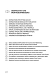
Examples of application
Fiber optic line
TELEPHONE SWITCH
E1 / G.703
E1 / G.703
TELPHONE SWITCH
Figure 1. TM-77.1 multiplexers used in telephone networks
ETHERNET
ROUTER
G.703
TELEPHONE SWITCH
MD-76.1
MD-76.1
LOES
Fiber optic line
LOES
L DF
-3
10
LOOS
RAL
A CK
NUA
-3
LOOS
-6
10
LOF
RAL
UA
A CK
NUA
AC K
ALACK
-6
10
L OF
UA
LD F
10
MD-77
A CK
ALACK
MD-77
4 x E1 / G.703
RING SDH
TRANSFER TERMINAL EQUIPMENT
TRANSFER TERMINAL EQUIPMENT
ETHERNET
4 x E1 / G.703
G.703
MD-76.1
ROUTER
LOES
LDF
LOOS
-3
MD-76.1
TELEPHONE SWITCH
-6
10
10
LOF
RAL
UA
AC K
N UA
ACK
ALACK
Fiber optic line
LOES
G.703
LDF
-3
10
LOF
MD-77
LOOS
-6
10
RAL
A CK
UA
NUA
A CK
ALACK
MD-77
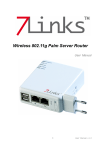
Figure 2. MD-77 multiplexers used to connect telephone switches and computer networks
using SDH network
IOA77-1G
2
August 2009
4XE1/G.703 PLESIOCHRONOUS MULTIPLEXER
OPERATING MANUAL
1.4
Symbols and available versions
TM - 77.1 - X - Y
Haul:
1 - short (SH)
2 - long (LH)
Type of optical transmitter:
3 - 1310 nm SM
4 - 1550 nm SM
5 - WDM 1310/1550 nm SM
6 - WDM 1550/1310 nm SM
Production version
Type of mechanical design:
TM - desktop version
MD - rack version
List of abbreviations:
SH – short haul
LH – long haul
MM – designed for operate with multi-mode fiber
SM - designed for operate with single-mode fiber
WDM – version to operate with single fiber, using WDM (Wavelength Division Multiplexing)
technology
1310 nm - transmitter working with 1310 nm wavelength, receiver working with 1310 nm
wavelength
1550 nm - transmitter working with 1550 nm wavelength, receiver working with 1550 nm
wavelength
1310/1550 nm - transmitter working with 1310 nm wavelength, receiver working with 1550 nm
wavelength
1550/1310 nm - transmitter working with 1550 nm wavelength, receiver working with 1310 nm
wavelength
E1 multiplexer is available in two versions:
• as a desktop version in a metal casing, symbol TM-77.
• as a card installed in TM-72 telecommunication rack to cooperate with another TM-72 or
MD-77 card.
Symbol example:
TM-77.1-3 – a desktop multiplexer equipped with a laser transmitter of 1310 nm wave
length.
IOA77-1G
3
August 2009
4XE1/G.703 PLESIOCHRONOUS MULTIPLEXER
OPERATING MANUAL
Note:
IOA77-1G
1. Each time a symbol containing the letter "X" instead of its corresponding
digit is used in the Manual, it means that the feature specified in this part
of the symbol is insignificant concerning the discussed parameter and may
be equal to any value from the above-mentioned range. However,
the device symbol indicated in a sales order must contain only digits
following the manufacturer symbol "TM" or "MD" (all features of the
ordered device must be specified).
4
August 2009
4XE1/G.703 PLESIOCHRONOUS MULTIPLEXER
OPERATING MANUAL
2 CONNECTORS AND INDICATORS
2.1
Introduction
Device versions differ from each other with the type of the used optical elements. There
are no differences in the mechanical structure.
3
TM-77.1
RS-232
4-SG
5-Rx
6-Tx
MULTIPLEXER 4xE1
1
2.2
LOES
2
4
LOOS 10 RAL ACK ACK
1
LDF 10
3
-6
-3
AACK
LOF UA NUA
4
2
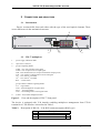
TM-77 multiplexer
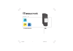
1-
power supply indication diode
2-
supervision connector
3-
group of signaling diodes:
LOES – loss of E1 interface input signal
LOOS – loss of optical receiver input signal
LDF– laser diode failure (loss of optical transmitter output power)
LOF – loss of frame synchronization of received signal
10-3 – error rate 10-3 exceeded
10-6 – error rate 10-6 exceeded
RAL – remote alarm
group of alarm condition signaling diodes:
UA – urgent alarm
ACK – acknowledgement of urgent alarm
NUA – non-urgent alarm
ACK – acknowledgement of non-urgent alarm
4-
AACK – alarm acknowledgment button
Figure 3. View and description of TM-77 front panel
The device is equipped with V.28 interface enabling multiplexer management from VT100
terminal level. The interface is described in Table 2.
Table 2.
Description of RS-232 / V.28 DCE connector outputs (RJ-45 type)
Pin
4
6
5
IOA77-1G
Description
SGND
Tx
Rx
5
OUT
IN
August 2009
4XE1/G.703 PLESIOCHRONOUS MULTIPLEXER
OPERATING MANUAL
RS-232 cable should be used to connect TM-77 multiplexer to the terminal. Table 3 specifies
the required list of cable connections.
Table 3.
PC computer (terminal) to TM-77 connecting cable specification
PC computer or terminal side
TM-77.1 multiplexer side
Pin symbol
DSUB-9 female connector
DSUB-25 female
connector
6
Tx
2
3
5
Rx
RTS – CTS
DTR - DSR
SGND
3
7–8
4–6
5
2
4–5
6 – 20
RJ-45 connector
4
P4
P1
9.22
10.23
P3
P2
7.19
8.20
P2
P3
4.17
5.18
7
P1
P4
2.14
3.15
4xE1 120Ω
3
1
5
2
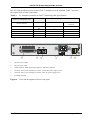
1-
optical receiver output
2-
optical receiver input
3-
120Ω symmetric linear signal inputs/outputs - DSUB-25 connector
4-
connector with a screw mounting to connect 36÷60V DC power supply source
5-
connector with a screw mounting to connect 230V AC power supply source
6-
grounding terminal
4
6
Figure 4. View and description of device rear panel
IOA77-1G
6
August 2009
4XE1/G.703 PLESIOCHRONOUS MULTIPLEXER
OPERATING MANUAL
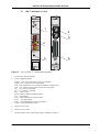
2.3
MD-77 multiplexer (card)
MD-77.1
1
4
5
2
AACK
6
3
MD-77.1
Figure 5. View of TM-77.1 front and rear panels
1 - power supply indication diode
2 - group of signaling diodes:
LOESn – loss of electrical signal coming in n-channel
LOOS – loss of optical receiver input signal
LDF– laser diode failure (loss of optical transmitter output power)
LOF – loss of frame synchronization of the received signal
10-3 – error rate 10-3 exceeded
10-6 – error rate 10-6 exceeded
RAL – remote alarm
group of alarm condition signaling diodes:
UA – urgent alarm
ACK – acknowledgement of urgent alarm
NUA – non-urgent alarm
ACK – acknowledgement of non-urgent alarm
3- AACK – alarm cancellation button
4- optical receiver input
5- optical receiver output
6
120 Ω symmetric linear signal input/output - DSUB-25 connector
IOA77-1G
7
August 2009
4XE1/G.703 PLESIOCHRONOUS MULTIPLEXER
OPERATING MANUAL
3 FUNCTIONAL DESCRIPTION
TM-77 and MD-77 devices perform the following functions:
1. processing of electrical signals at the bit rate of 2.048 Mbit/s in HDB-3 three-level code into
a digital signal in the natural code;
2. multiplexing of four data streams at the bit rate of 2.048 Mbit/s according to the G.742
recommendation;
3. encoding in 5B/6B code;
4. processing an electrical signal into an optical one;
5. receiving of an optical signal and processing it into an electrical signal;
6. decoding of a data stream encoded in 5B/6B code;
7. demultiplexing of four data streams at the bit rate of 2.048 Mbit/s;
8. encoding of a data stream at the bit rate of 2.048 Mbit/s in HDB-3 code;
9. control and signaling of the basic parameters of the multiplexer operation and generation
of alarms in the event of failures.
3.1
Diagnostic and signaling systems
TM-77 and MD-77 type devices automatically control the parameters of E1/G.703 local
interface and linear optical signal, and detect and signalize the following conditions and values:
•
•
•
•
G.703 E1 local interface
loss of interface input signal
receiving of AIS signal coming from E1 interface
receiving of AIS signal coming from demultiplexer
HDB3 code violation
•
•
•
•
Linear optical interface:
loss of linear input signal
loss of frame synchronization of the received signal
block error rates 1x10⁻³ and 1x10⁻⁶ exceeded
receiving of the AIS bit in G.742 frame signaling a remote alarm
•
•
•
An alarm condition is indicated as follows:
appropriate local interface LED is switched on: LOES
appropriate optical interface LED is switched on: LOOS, LOF, 10-3, 10-6, RAL, LDF
shorting of UALA, NUALA alarm relay terminals in TM-72 telecommunication rack.
When a failure is detected, a "non-urgent" alarm – NUA (indicating a failure condition,
which does not interrupt transmission) or an "urgent" alarm – UA (meaning a transmission
interruption - an immediate operator's response is necessary) is generated.
MD-77 device card signalizes generation of an urgent or non-urgent alarm by sending
a signal to activate the alarm relays in TM-72 rack. The urgent and non-urgent alarm signaling
relay contacts in the telecommunication rack are connected to DSUB- 9 female socket.
The detected failure conditions and actions taken are shown in Table 1.
IOA77-1G
8
August 2009
4XE1/G.703 PLESIOCHRONOUS MULTIPLEXER
OPERATING MANUAL
Table 4.
Detected failure conditions and accompanying actions.
Actions taken
Rela
y 1)
UA
Error rate
> 10-3
UA
Linear optical
interface
Error rate
> 10-6
Transmitter
failure
;
;
;
;
NUA
C O
AIS signals are
transmitted to all E1
interfaces
;
C O
AIS signals are
transmitted to all E1
interfaces
;
O C
AIS signals are
transmitted to all E1
interfaces
;
C O
---
;
UA
--;
Remote alarm
G.742
frame
bit
AIS
Loss of frame
synchronization
E1 channel signal
LDF
RAL
LOES
UA
NUA
UA
10-6
Loss of signal
Failed
element
LOOS
LOF
10-3
Failure
condition
Alarm
LED diode
---
Local
interface
E1
G.703,
G.704
Loss of signal
UA
C O
AIS signal is transmitted
via E1 channel to
multiplexer
Entire device
Loss of power
supply
UA
C C
;
; – LED diode is on
1)
– alarm relay, an activated alarm is indicated by closed relay contacts (C – closed contacts,
O – open contacts). TM-77.1 version is not equipped with alarm relays.
3.2
Additional channels
A frame is generated in the multiplexing system. The frame includes two bits, which
are used to generate two additional synchronous bidirectional data transmission channels
at the speed of 10 kbit/s each.
The first of the bits – Alarm Indication Signal Bit - is used to transmit an alarm signal
to a remote device.
The other bit - National Bit - is used for communication between the supervision systems of
a local and remote device.
IOA77-1G
9
August 2009
4XE1/G.703 PLESIOCHRONOUS MULTIPLEXER
OPERATING MANUAL
3.3
Test loops
TM-77.1 and MD-77.1 device software enables closing a loop on E1 electric interface
and optical interface in the direction to and from the device. Concerning E1 interface, both loops
are closed at the same time. The figure below shows possible loops. A loop number is consistent
with the number used in the device software.
1
E1 port
Mux
E1 port
Optical por t
E1 port
Demux
E1 port
Figure 6. Loops
3.4
Clock transfer
TM-77 and MD-77 devices are based on a plesiochronous multiplexer compliant with ITUT G.742 standard. 2Mbit/s signals received on G.703 E1 electric interfaces are transmitted
separately. E2 linear optical interface collective signal clock is also separate from the clock
signals generated in E1 interface. The requirement is that the clock signal frequency restored on
E1 interface must be in accordance with ITU-T G.703 recommendation (2048 MHz ± 50ppm).
IOA77-1G
10
August 2009
4XE1/G.703 PLESIOCHRONOUS MULTIPLEXER
OPERATING MANUAL
3.5
Event log
TM-77 and MD-77 devices can record the time and date of an event of a specified
criterion. The devices record the following types of events:
•
•
•
•
•
•
•
•
•
•
•
•
•
•
an appearance or loss of power supply voltage,
an appearance or loss of G.703 E1 interface input signal,
an appearance or loss of AIS signal transmitted from a unit connected to E1 interface or
connected to E1 channel with E2 collective signal,
an appearance or loss of E2 optical interface input signal,
a gain or loss of G.742 frame synchronization on E2 optical interface,
exceeding or going below 10-3 error rate threshold on E2 optical interface,
exceeding or going below 10-6 error rate threshold on E2 optical interface,
exceeding or going below a user-defined ES 15-minute errored second counter (ES15)
threshold – there is a separate counter for each interface,
exceeding or going below a user-defined ES 24-hour errored second counter (ES24)
threshold – there is a separate counter for each interface,
exceeding or going below a user-defined SES 15-minute severely errored second counter
(SES15) threshold – there is a separate counter for each interface,
exceeding or going below a user-defined SES 24-hour severely errored second counter
(SES24) threshold – there is a separate counter for each interface,
activation or deactivation of test loops,
approval of a device set-up modification,
an attempt of unauthorized access to the device set-up system using VT100 terminal
emulator, if the system is password-protected.
Reviewing and deleting the event log as well as defining maximum and minimum
threshold values for ES15,24 and SES15,24 counters of E1 and E2 interfaces is possible with
the Lanwin application or VT100 terminal emulator described in sections 5.5.4 Event log
and 6.6.1 Event log.
IOA77-1G
11
August 2009
4XE1/G.703 PLESIOCHRONOUS MULTIPLEXER
OPERATING MANUAL
3.6
Monitored qualitative parameters of G.703 E1 interface
TM-77 and MD-77 devices are provided with a function of qualitative parameter monitoring.
The devices automatically monitor the interface signal parameters and detect, count and signalize
the following conditions and parameters:
•
•
•
•
LOES
VIOL
AISL
AISR
-
•
•
•
•
ES15
SES15
ES24
SES24
-
Indicators:
loss of electrical signal
HDB3 code violation on G.703 E1 optical interface
AIS signal detection on G.703 E1 interface
AIS signal detection in E1 flux demultiplexed from E2 collective
channel.
exceeding a 15-minute errored second counter threshold
exceeding a 15-minute severely errored second counter threshold
exceeding a 24-hour errored second counter threshold
exceeding a 24-hour severely errored second counter threshold
-
Counters:
15-minute errored second counter
15-minute severely errored second counter
24-hour errored second counter
24-hour severely errored second counter
15-minute background block error counter
24-hour background block error counter
15-minute unavailability second counter
24-hour unavailability second counter
•
•
•
•
•
•
•
•
ES15
SES15
ES24
SES24
BBE15
BBE24
UAS15
UAS24
IOA77-1G
12
August 2009
4XE1/G.703 PLESIOCHRONOUS MULTIPLEXER
OPERATING MANUAL
3.7
Monitored qualitative parameters of E2 optical interface
TM-77 and MD-77 devices are provided with a function of qualitative parameter monitoring.
The devices automatically monitor the linear interface signal parameters and detect, count
and signalize the following conditions and parameters:
•
•
•
•
•
•
LOOS
LDF
LOF
10E-3
10E-6
RAL
-
•
•
•
•
•
ES15
SES15
ES24
SES24
SESFE15
-
•
SESFE24
-
Indicators:
loss of optical signal
laser diode failure
loss of frame synchronization
error rate 10-3 exceeded
error rate 10-6 exceeded
remote device alarm indicating a remote device connection failure
(between a local and remote device)
exceeding a 15-minute errored second counter threshold
exceeding a 15-minute severely errored second counter threshold
exceeding a 24-hour errored second counter threshold
exceeding a 24-hour severely errored second counter threshold
exceeding a 15-minute severely errored second far end counter
threshold
exceeding a 24-hour severely errored second far end counter threshold
-
Counters:
15-minute errored second counter
15-minute severely errored second counter
24-hour errored second counter
24-hour severely errored second counter
15-minute severely errored second far end counter
24-hour severely errored second far end counter
15-minute background block error counter
24-hour background block error counter
15-minute unavailability second counter
24-hour unavailability second counter
•
•
•
•
•
•
•
•
•
•
ES15
SES15
ES24
SES24
SESFE15
SESFE24
BBE15
BBE24
UAS15
UAS24
IOA77-1G
13
August 2009
4XE1/G.703 PLESIOCHRONOUS MULTIPLEXER
OPERATING MANUAL
4 INSTALLATION AND OPERATION
4.1
Operating conditions
The devices can operate continuously in closed rooms and in conditions according
to paragraph 7.4.1 of this Operating Manual. The devices should not be directly exposed
to sunlight. Ventilation slots must not be plugged. We do not recommend to put the devices on
heat sources, although they can be placed on another device of the same type or installed in
a rack together with other devices. However, such an arrangement requires a free air flow or,
if necessary, forced ventilation.
4.2
Installation
TM-77 is a desktop device; MD-77 is installed in MD-72 telecommunication rack.
MD-77 device comprises a digital card and an interface card. The digital card is installed in
the front part of the rack in slots 1÷16 and the interface card is installed in their corresponding
slots in the rear part of the rack. The cards are equipped with pullers for easy assembly
and disassembly in TM-72 rack. The cards can be installed in the rack without a need to turn off
the power supply. There is no specific sequence of assembly of the digital card and interface
card.
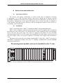
The figures below show the rack with the installed MD-77 card (slot 1), MD-77 card (slot 2)
and MD-91 management module card (slot 17) enabling communication with the Lanwin
management application.
The management module card can be installed in slot 17 only.
Figure 7. Device installation in form of MD-72 telecommunication rack card, front view.
IOA77-1G
14
August 2009
5
E1 120W
2
7
S
4XE1/G.703 PLESIOCHRONOUS MULTIPLEXER
OPERATING MANUAL
MD-76.1 MD-77.1
Figure 8. Device installation in form of MD-72 telecommunication rack card, rear view.
Figure 9. Installation of the devices in the form of a card in MD-72 telecommunication rack,
sectional view.
4.3
Power supply
TM-77 multiplexer can be supplied with 36÷60V DC voltage or 230V AC voltage. MD-77
card is supplied with 18÷60V DC voltage from TM-72 telecommunication rack. Power supply
connection is described in TM-72 rack operating manual. Power supply voltage parameters are
given in paragraph 7.6.
The correct power supply of the device is signalized by a light indicator
on the front panel.
36÷60V power supply unit voltage should be connected to the socket with external screw
connections. There is no requirement concerning polarity of power supply voltage.
The grounding should be connected to the grounding terminal on the casing. The grounding
cable should have low impedance for high frequencies.
Note. The device has no built-in disconnecting system, thus an easily accessible
disconnecting system should be mounted into the fixed cabling.
IOA77-1G
15
August 2009
4XE1/G.703 PLESIOCHRONOUS MULTIPLEXER
OPERATING MANUAL
4.4
E1/G.703 linear signal connection
4.4.1 TM-77 and MD-77
E1/G.703 interface input and output signals of TM-77 and MD-77 devices are transmitted
via two screened symmetric cables of 120 Ω impedance or one double screened cable of the
same impedance.
The following rules should be observed to meet the requirements concerning noise
emissions. Symmetric cables should be connected using DSUB-25 plug equipped with a metal or
metalized casing (shield) and the cable screen should be connected to the casing over the whole
circumference. It is insufficient just to connect the screen to the "structural earth" terminals on
the E1/G.703 120Ω interface socket.
The E1/G.703 120 Ωlinear module socket outputs are described in Table 5.
Table 5.
IOA77-1G
Description of TM-77 and MD-77 E1/G.703 120Ω interface outputs
Pin
No.
Description of outputs
1
2
3
4
5
6
7
8
9
10
11
12
13
14
15
16
17
18
19
20
21
22
23
24
25
GND
RX_B4
TX_B4
RX_A3
TX_A3
GND
RX_B2
TX_B2
RX_A1
TX_A1
GND
GND
Not connected
RX_A4
TX_A4
GND
RX_B3
TX_B3
RX_A2
TX_A2
GND
RX_B1
TX_B1
GND
Not connected
16
August 2009
4XE1/G.703 PLESIOCHRONOUS MULTIPLEXER
OPERATING MANUAL
4.5
Connection to VT100 terminal or a computer with the installed Lanwin
management software.
TM-77 device is equipped with RS-232 interface enabling multiplexer management from
the level of VT100 terminal or using the Lanwin software. The interface is described in Table 6.
Table 6.
Description of RS-232 / V.28 DCE connector outputs (RJ-45 type)
Pin
Description
4
6
5
SGND
Tx
Rx
OUT
IN
RS-232 cable should be used to connect TM-77 multiplexer to the terminal. Table 7 specifies the
required list of cable connections.
Table 7.
TM-77 - computer connecting cable specification
PC computer or terminal side
TM-77.1 multiplexer side
RJ-45 connector
6
5
4
Pin symbol
DSUB-9
female connector
2
3
7–8
4–6
5
Tx
Rx
RTS – CTS
DTR - DSR
SGND
DSUB-25 female
connector
3
2
4–5
6 – 20
7
MD-76 and MD-77 cards in TM-72 rack can be managed with the Lanwin software
installed on a PC computer. TM-72 rack must be equipped with MD-91 management card.
The managing computer should be connected to the rack with the cable specified in the table
below.
Table 8.
TM-72 - computer connecting cable specification.
TM-72 rack MD-91 card
side
DSUB-9 connector
(female)
2
3
4
casing
IOA77-1G
PC computer or terminal side
Pin symbol
DSUB-9
female connector
2
3
7–8
4–6
5
casing
Tx
Rx
RTS – CTS
DTR - DSR
SGND
17
DSUB-25 female
connector
3
2
4–5
6 – 20
7
casing
August 2009
4XE1/G.703 PLESIOCHRONOUS MULTIPLEXER
OPERATING MANUAL
4.6
Fiber optic line connection
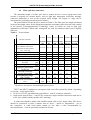
The maximum length of a fiber optic line to connect devices is not a unequivocal value
because it depends on external factors, such as light pipe attenuation coefficient, throughconnector attenuation as well as the accepted safety margin. The length, i.e. range can be
determined by performing an optical power balance.
The power balance for the devices is shown in Table 9. The fiber optic line length calculated
in the are maximum values for the adopted assumptions (maximum values from the cable catalog
of the Optical Telecommunications Technology Center in Lublin are used as light pipe
attenuation coefficients). When other assumption are used, the obtained values can be slightly
different.
Table 9.
Power balance
77.1-3-1 77.1-3-1 77.1-3-2 77.1-4-1 77.1-5/6-1 77.1-5/6-2
Device version
LASER LASER LASER LASER WDM
WDM
1310 nm 1310 nm 1310 nm 1550 1310/1550 1310/1550
SH
SH
LH
nm SH nm SH
nm LH
Wave length
1
(for WDM have been done
calculation for unfavourable
case - 1310 nm)
2 Type of optical fiber
3 Transmitter power level [dBm]
Receiver sensitivity [dBm]
4
Power budget (3-4) [dBm]
5
6
7
8
9
10
11
1)
Power margin for
devices
[dB]
Power margin for cable [dB]
Light pipe attenuation
coefficient
[dB/km]
Through-connector
average attenuation
[dB]
Transmission range
(5-6-7)/(8+9)
[km]
Minimum line attenuation
[dB]
1310 nm 1310 nm 1310 nm 1550 nm 1310 nm
1)
1310 nm
SM
-15
-35
20
MM
-15
-35
20
SM
-5
-36
31
SM
-5
-35
30
SM
-14
-31
20
SM
-8
-34
26
4
2
4
2
4
3
4
3
4
2
4
3
0,4
1
0,4
0,2
0,4
0,4
0,1
0,2
0,1
0,1
0,1
0,1
28
12
48
77
22
38
0 dB
0 dB
0 dB
0 dB
0 dB
0 dB
The device can operate with multimode optical fibers.
TM-77 and MD-77 multiplexers can operate with a two-fiber optical line based - depending
on version - on the optical fibers:
• 50/125 or 62.5/125 µm multimode optical fibers - with SC connector terminals;
• single-mode optical fibers - with SC/PC connectors (angle terminal connectors must not be
used - their symbol usually includes APC marking).
A connection should be made with a double station cable or two single cables. The device
should be positioned in such a manner that no forces - lateral or longitudinal - act on
the connectors. A cable bend radius cannot be less than a value recommended by
the manufacturer - it can be practically assumed as 50 mm.
IOA77-1G
18
August 2009
4XE1/G.703 PLESIOCHRONOUS MULTIPLEXER
OPERATING MANUAL
Optical fiber connectors - particularly single-mode ones - are very precise components. That
is why they should be handled with care, with no excessive forces when connecting
and disconnecting them. Also the socket and the plug "ferrule" should be kept ideally clean.
If dirty, the socket can be blown with clean compressed air, while the ferrule can be cleaned with
isopropyl or ethyl alcohol (denatured alcohol must not be used). A piece of cloth, which does not
leave fibers, should be used for this purpose.
The diameter of the single-mode optical fiber core is only 9 µm. Thus any contamination
particles of similar size may cause significant signal attenuation and completely disable
transmission.
If no optical fiber plugs are connected to the device, the sockets should be always secured
with protective caps to avoid dust penetration.
The following steps should be performed to make a connection:
•
remove the protective caps from the socket and the plug ferrule;
•
put the ferrule into the socket end caring of accurate alignment of the socket and plug axes
- any attempts of pushing the plug "obliquely" can damage the connector. Pay attention to place
the key located on the plug circumference (outside the ferrule) in the notch in the socket;
•
tighten the connector nut until slight resistance is felt.
Please remember that the fiber optic line connected from one side to the optical transmitter should be connected to the receiver from the other side. This fact will be indicated by the red
diode "LOOS", which will go out. A reverse connection is not harmful but of course the devices
will not function ("LOOS" diodes in both multiplexers will be on and AIS signal will be sent to
E1/G.703 interfaces).
Any manipulations of fiber optic connectors may be performed when the power supply is on.
The optical transmitter may be connected to the receiver of the same multiplexer with a short
section of an optical cable in order to close the "local loop" and take measurements.
NOTE !
Radiation transmitted by the laser transmitter is harmful to eyes! It is indicated
by the following symbol placed on the device:
Never look at the uncovered socket without a plugged-in fiber optic connector. The transmitter
emits full power always when the device is on - with or without a signal connected
to the electrical input.
IOA77-1G
19
August 2009
4XE1/G.703 PLESIOCHRONOUS MULTIPLEXER
OPERATING MANUAL
5 OPERATION WITH VT100 TERMINAL
5.1
Application
The supervision software is adapted to support VT100 terminal; it is used to set up
and monitor the functions of TM-77 multiplexer. MD-77 device is installed in the rack
and it does not have a contact enabling terminal connection.
The software provides the following features:
Activation / deactivation of component channels;
Installation of test loops in a local device
ES, SES, UAS and BBE monitoring
Monitoring the following events:
Loss of optical signal
Transmitter failure
Loss of frame synchronization
Alarm from a remote device
Loss of signal component
Exceeding 10-3 error rate;
Exceeding 10-6 error rate;
HDB3 code violation in a component channel
AIS signal detection on E1 interface
AIS signal detection in E1 flux demultiplexed from E2 collective
channel
Alarm status monitoring:
Active;
Inactive;
Generation of event logs
5.2
Hardware requirements
There are many programs enabling VT100 terminal emulation, which operate on
various hardware platforms and support various operating systems. The most popular are
TERM95 included in Norton Commander package supporting DOS environment or
HYPERTERMINAL supporting Windows (both for PC-class computers).
IOA77-1G
20
August 2009
4XE1/G.703 PLESIOCHRONOUS MULTIPLEXER
OPERATING MANUAL
5.3
Installation and start-up
In order to start up the supervision software, VT100 terminal or a VT100 terminal
emulation program should be correctly set up.
The tables below show examples of TERM95 and HYPERTERMINAL setup. If another
program is used, the user should set the appropriate parameters based on the user manual
of the program:
Transmission speed
Data bits
Parity
Stop bits
Flow control
Emulation
9600
8
none
1
none
VT100
Table 10. VT100 terminal settings for "TERM95" program
TERM95
Speed
number of data bits
number of stop bits
flow control
local echo
terminal type
9600
8
1
none
none
VT100
Table 11. VT100 terminal settings for "HYPER TERMINAL" program
HYPERTERMINAL
bits per second
Data bits
Parity
Stop bits
flow control
Font
local echo of entered characters
5.4
9600
8
none
1
none
terminal
none
Beginning the terminal operation
After the device is started up and RS-232 interfaces are connected, enter the START command
and press the ENTER button. The command may be entered in small or capital letters.
When the command is identified, TM-77 opens the first window specifying the device type
and its address. Then the password entry window opens. It allows the user to enter the password
protecting from unauthorized access to the device. If the password is not active, it is sufficient
to press ENTER.
IOA77-1G
21
August 2009
4XE1/G.703 PLESIOCHRONOUS MULTIPLEXER
OPERATING MANUAL
Figure 10. Password entry panel
EMERGENCY PASSWORD REMOVAL!!
If the user forgets the password, he/she can remove it by performing an emergency
procedure.
To do this, the user - instead of the password - should enter %code01. Then, the program
will generate an 8-digit string, which should be submitted to the LANEX service. Based on
the string, an emergency password will be generated enabling 12-hour access to the device.
Within a period of 12 hours, the password allows the user to delete the old password
and enter a new one.
IOA77-1G
22
August 2009
4XE1/G.703 PLESIOCHRONOUS MULTIPLEXER
OPERATING MANUAL
5.5
Main menu
The main menu is the entry window to all remaining panels and submenus.
Submenus are selected with the ARROWS and ENTER keys.
From its level, you can access the following panels:
• System
• Interfaces
• Event log
• Monitoring
• Loops
• About the program
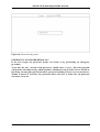
Figure 11. The Main menu
The operation needs only the ARROWS, BACKSPACE, SPACE, ENTER keys
and a combination of some other keys, e.g. CTRL+X. The user is forced to "manually" exchange
information with the terminal only when really necessary (entry and modification of clock,
password, device name).
IOA77-1G
23
August 2009
4XE1/G.703 PLESIOCHRONOUS MULTIPLEXER
OPERATING MANUAL
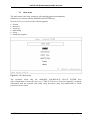
Each of the available panels comprises three fields (common to all panels). These are:
• panel name and date bar,
• device name and address bar,
• key shortcut bar.
1.
2.
3.
Figure 12. A terminal window example
1. active panel name and current date and system clock bar
2. device name and address bar
3. key shortcut bar indicating operations available in a given panel
5.5.1
•
•
•
•
•
System
The System panel allows the user to:
modify the device name,
activate the password and enter a new one (you will be prompted to give the password during
the terminal start-up)
modify the system time and date,
set the full or reduced laser power,
specify the counting base time in 15-minute and 24-hour periods
IOA77-1G
24
August 2009
4XE1/G.703 PLESIOCHRONOUS MULTIPLEXER
OPERATING MANUAL
Figure 13. The System panel
The parameters set up in the System panel are listed in Table 12.
Table 12. Device set-up registers. The values in the gray fields in the table are given
in the phase of production. Any subsequent modification by the user is impossible.
Parameter name
Allowed status
Default
value
Device type
Software version
Hardware version
Device address
TM – 77
-------
---------
Serial No.
---
---
Device name
16 – character text
TM – 77.1
Access password
8 – character text
---
System time
Digits for individual
elements of date and time
---
Language
Laser
Polish or English
Full power
Polish
---
Counting start
Two digits for hour and
minute
00:00
5.5.2
Description
Type of configured device
Device software version number
Device hardware version
Device address given in production
Number given to the device in
production
Any device name given by the user
Password protecting from
unauthorized access to the device
System clock arrangement:
Date – yyyy,mm,dd
Time – hh,mm,ss
Language selection
Laser transmitter operation status
Hour and minute of count start for ES
and SES registers in the following
arrangement: hh,mm
Interfaces-selection
This panel allows the user to select the interface to set up and monitor the quality
parameters of the interface and its activation.
IOA77-1G
25
August 2009
4XE1/G.703 PLESIOCHRONOUS MULTIPLEXER
OPERATING MANUAL
Figure 14. Interfaces-selection
5.5.2.1
Interfaces-options
The Interfaces-options panel is used to select the following panels:
• interface set-up,
• viewing 15-minut and 24-hour ES, SES, BBE, UAS, ESFE, SESFE registers,
• viewing the objects related to quality monitoring in the set periods
Figure 15. Interfaces-options
IOA77-1G
26
August 2009
4XE1/G.703 PLESIOCHRONOUS MULTIPLEXER
OPERATING MANUAL
5.5.2.2 Set-up
The Set-up panel is used to:
• set up alarm severity levels when exceeding the quality thresholds in 15-minute
and 24-hour periods, set up alarm switch-on and switch-off thresholds when exceeding
the quality thresholds in 15-minute and 24-hour periods,
• set up alarm switch-on and switch-off thresholds when exceeding the quality thresholds
in 15-minute and 24-hour periods
Figure 16. Interfaces - set-up
Alarm severity levels when exceeding the switch-on threshold can be as follows:
UAL – urgent alarm,
NUAL – non-urgent alarm
NONE – no alarm is generated
A switch-on threshold defines the number of seconds, after exceeding of which an alarm
specified by a severity level is activated.
A switch-off threshold defines the number of seconds, which specifies deactivation
of an alarm specified by a severity level, if the counted number of seconds is less or equal
to the threshold at the end of a given period.
The table below shows allowable alarm statuses (severity levels) and allowable values
of alarm switch-on and switch-off thresholds when exceeding ES and SES threshold values.
•
•
•
IOA77-1G
27
August 2009
4XE1/G.703 PLESIOCHRONOUS MULTIPLEXER
OPERATING MANUAL
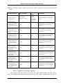
Table 13. Interface set-up – alarm severity level values, switch-on and switch-off threshold
values.
Parameter name
ES/SES threshold
exceeding alarm
Threshold value of
switching on an urgent
alarm after SES was
exceeded in a 15-minute
period
Threshold value of
switching off an urgent
alarm after SES was
exceeded in a 15-minute
period
Threshold value of
switching on an urgent
alarm after SES was
exceeded in a 24-hour
period.
Threshold value of
switching off an urgent
alarm after SES was
exceeded in a 24-hour
period
Threshold value of
switching on a nonurgent alarm after ES
was exceeded in a 15minute period
Threshold value of
switching off a nonurgent alarm after ES
was exceeded in a 15minute period.
Threshold value of
switching on a nonurgent alarm after ES
was exceeded in a 24hour period
Threshold value of
switching off a nonurgent alarm after SES
was exceeded in a 24hour period
Allowed status
Default
value
Description
Urgent alarm
Non-urgent alarm
None
Urgent alarm
for SES
counters
Non-urgent
alarm for ES
counters
ES/SES threshold exceeding alarm
activity
0..900
15
Value for SES in a 15-minute period,
above which an urgent alarm is
switched on
0..900
0
Value for SES in a 15-minute period,
below which an urgent alarm is
switched off.
0..86400
1440
Value for SES in a 24-hour period,
above which an urgent alarm is
switched on
0..86400
0
Value for SES in a 24-hour period,
below which an urgent alarm is
switched off
0..900
120
Value for ES in a 15-minute period,
above which a non-urgent alarm is
switched on
0..900
0
Value for ES in a 15-minute period,
below which a non-urgent alarm is
switched off.
0..86400
11520
Value for ES in a 24-hour period,
above which a non-urgent alarm is
switched on
0..86400
0
Value for ES in a 24-hour period,
below which a non-urgent alarm is
switched off
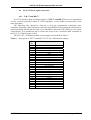
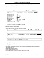
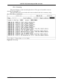
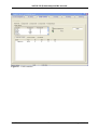
5.5.2.3 15-minute and 24-hour registers
These panels allow the operator to monitor ES, SES, SESFE, BBE and UAS counter
values in 15-minute and 24-hour periods, respectively. The "alarm" columns show the type of
IOA77-1G
28
August 2009
4XE1/G.703 PLESIOCHRONOUS MULTIPLEXER
OPERATING MANUAL
an alarm generated by exceeding an appropriate switch-on threshold (which is set up in
the Set-up panel). The device stores 16 records of 15-minute counters for each interface and
2 records of 24-hour counters for each interface. Data is recorded only for non-zero counter
values.
Figure 17. 24-hour registers
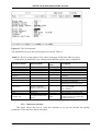
5.5.3
Time periods
This panel is used to monitor ES, SES, BBE rates in any two time periods specified
by the operator.
Figure 18. Time periods
IOA77-1G
29
August 2009
4XE1/G.703 PLESIOCHRONOUS MULTIPLEXER
OPERATING MANUAL
5.5.4
Event log
This panel displays events concerning the device. The types of recorded events are
described in paragraph 3.6.
This panel allows the user to delete all events recorded in the device memory using
the CTRL+R key combination.
Figure 19. Event log
IOA77-1G
30
August 2009
4XE1/G.703 PLESIOCHRONOUS MULTIPLEXER
OPERATING MANUAL
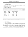
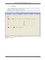
5.5.5
Monitoring
This panel displays parameters, which represent the current status of E1 and E2 interfaces:
• interface defect and anomaly monitoring points,
• transmission quality monitoring objects related to individual interfaces. The meaning
of individual indicators is described in paragraph 3.6.
Figure 20. Monitoring
IOA77-1G
31
August 2009
4XE1/G.703 PLESIOCHRONOUS MULTIPLEXER
OPERATING MANUAL
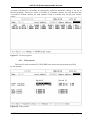
5.5.6 Loops
TM-77 multiplexer terminal is capable of activating test loops from the side of E1 and E2
interfaces. The test loops are described in paragraph 3.3 Test loops.
Figure 21. Loops
IOA77-1G
32
August 2009
4XE1/G.703 PLESIOCHRONOUS MULTIPLEXER
OPERATING MANUAL
6 DEVICE SET-UP USING LANWIN PROGRAM
The Lanwin application in a local version enables the user to supervise and monitor TM-77
in a desktop version and TM-72 racks equipped with MD-77 multiplexer cards. The description
of computer connection is given in paragraph 4.5 Connection to VT100 terminal or computer
equipped with LanWin management software.
6.1
Global set-up
This tab allows the user to enter the name of the device, to set the system date and time and
to view additional device information.
Figure 22. Global set-up
IOA77-1G
33
August 2009
4XE1/G.703 PLESIOCHRONOUS MULTIPLEXER
OPERATING MANUAL
6.1.1
Device name
By pressing the "Device name" button you will opens a window, in which you can enter its
name. During the operation, the entered name will appear in the active device window
and in the window of the device, whose name was modified.
Figure 23. Device name
6.1.2
Setting date and time
If you press the "Setting time and date" button, the following window will open.
Figure 24. Setting date and timeAfter you make any modifications and press the "OK" key,
the system time and date parameters of the device will be updated.
IOA77-1G
34
August 2009
4XE1/G.703 PLESIOCHRONOUS MULTIPLEXER
OPERATING MANUAL
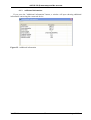
6.1.3
Additional information
If you press the "Additional information" button, a window will open showing additional
information concerning the connected device.
Figure 25. Additional information
IOA77-1G
35
August 2009
4XE1/G.703 PLESIOCHRONOUS MULTIPLEXER
OPERATING MANUAL
6.2
Channel activity
The "Channel activity" tab allows the user to switch on and off a single E1 transmission
channel. If you switch off a channel, it will block transmission in the channel and deactivate all
alarm criteria associated with the channel.
Figure 26. Channel activity
6.3
G.826 statistics
This tab enables the user to monitor the following numbers in 15-minut and 24-hour
periods:
• ES errored seconds,
• SES severely errored seconds,
• EB errored bloks,
• UAS unavailability seconds,
Additionally, you can set threshold values for switching on and off the alarms for SES15,
SES24, ES15, ES24, SESFE15, SESFE24 counters, based on which event log entries and alarms
are generated. Each counter has an associated alarm severity level identifying the type
of a generated alarm.
The user can set the following alarm severity levels:
• urgent alarm,
• non-urgent alarm,
• no alarm.
IOA77-1G
36
August 2009
4XE1/G.703 PLESIOCHRONOUS MULTIPLEXER
OPERATING MANUAL
Figure 27. G.826 statistics
IOA77-1G
37
August 2009
4XE1/G.703 PLESIOCHRONOUS MULTIPLEXER
OPERATING MANUAL
6.3.1
Alarm severity level
The window shown below allows you to set an alarm severity level. The window will open
if you select the "Alarm severity level" option from the Menu.
Figure 28. G.826 statistics, Alarm severity level
IOA77-1G
38
August 2009
4XE1/G.703 PLESIOCHRONOUS MULTIPLEXER
OPERATING MANUAL
6.3.2
Alarm thresholds
The window shown below allows you to set an alarm switch-on and switch-off threshold.
The window will open if you select the "Threshold set-up" option from the Menu.
Figure 29. G.826 statistics, Alarm thresholds
IOA77-1G
39
August 2009
4XE1/G.703 PLESIOCHRONOUS MULTIPLEXER
OPERATING MANUAL
6.4
Test loops
The tab "TM-77 test loops" allows you to activate the test loops from the side of E1 and E2
interfaces. The test loops are described in paragraph 3.3 Test loops.
Figure 30. Test loops
IOA77-1G
40
August 2009
4XE1/G.703 PLESIOCHRONOUS MULTIPLEXER
OPERATING MANUAL
6.5
Monitoring
This panel displays parameters, which represent the current status of E1 and E2 interfaces:
• interface defect and anomaly monitoring points,
• transmission quality monitoring objects related to individual interfaces. The meaning
of individual indicators is described in paragraph 3.7.
Figure 31. Monitoring
IOA77-1G
41
August 2009
4XE1/G.703 PLESIOCHRONOUS MULTIPLEXER
OPERATING MANUAL
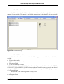
6.6
6.6.1
Log
Event log
The "Event log" tab displays the recorded events concerning the multiplexer. The types
of recorded events are described in paragraph 3.5. This tab allows you to delete the complete list
of recorded events. You can do this by clicking the right mouse button (when the cursor is placed
in this window) and selecting the "Delete the log" command.
Figure 32. Log
6.6.2
Event log filter
This tab is divided into two parts. The top part of the tab displays events, which are the result
of the filtering of all recorded events (displayed in the "Event log" tab).
The left bottom part of the window shows three component tabs. They allow you to select
the event filtering criteria.
List of filtering criteria tabs
• Events
It allows you to select and display only events of one type from the above
list of recorded events.
• Date
IOA77-1G
42
August 2009
4XE1/G.703 PLESIOCHRONOUS MULTIPLEXER
OPERATING MANUAL
•
It allows you to select an event filtering time criterion. This tab enables you to
select the start and end date and time of this criterion.
UAL/NUAL
It allows you to select criteria of the displayed events analogous to the ones specified
for:
• Urgent alarm criteria (paragraph 3.1),
• Non-urgent alarm criteria (paragraph 3.1),
• other criteria (not included in the urgent and non-urgent alarm criteria).
The following two buttons are displayed in the right part of the window:
• "Filter" - it displays events of the type and value such as in the tab on the left.
"OR" - it displays events using the criteria from all tabs.
Figure 33. Event log filter
IOA77-1G
43
August 2009
4XE1/G.703 PLESIOCHRONOUS MULTIPLEXER
OPERATING MANUAL
7 TECHNICAL SPECIFICATION
7.1
Electrical characteristics of E1/G.703 interface
Parameter
or feature
Parameter value
or feature description
Electrical compatibility
ITU-T G.703
standard
Rated binary bit rate
2.048 Mbit/s ±50 ppm
AIS signal binary bit rate
2.048 Mbit/s ±50 ppm
Input and output impedance
120Ω - symmetric connector
Maximum cable attenuation
6 dB
coefficient for 1024kHz
frequency
Linear code
HDB-3
1)
Error rate
≤10-9
Connector type
DSUB-25
1)
at the power level at the receiver input not lower than the value specified in paragraph 7.2
as "receiver sensitivity"
IOA77-1G
44
August 2009
4XE1/G.703 PLESIOCHRONOUS MULTIPLEXER
OPERATING MANUAL
7.2
Optical interface characteristics
Parameter
or feature
Linear code
Optical signal modulation speed
Optical transmitter type
Level of power optical transmitter
Receiver sensitivity
(minimum value for error rate ≤ 10-9 )
Types of fiber optic connectors
IOA77-1G
Version
Symbol
TM 77.1-X
MD 77.1-X
TM 77.1-X
MD 77.1-X
TM 77.1-3-X
MD 77.1-3-X
TM 77.1-4-X
MD 77.1-4-X
TM 77.1-5-X
MD 77.1-5-X
TM 77.1-6-X
MD 77.1-6-X
TM 77.1-3-1
MD 77.1-3-1
TM 77.1-3-2
MD 77.1-3-2
TM 77.1-4-1
MD 77.1-4-1
TM 77.1-5-1
MD 77.1-5-1
TM 77.1-5-2
MD 77.1-5-2
TM 77.1-6-1
MD 77.1-6-1
TM 77.1-6-2
MD 77.1-6-2
TM 77.1-3-1
MD 77.1-3-1
TM 77.1-3-2
MD 77.1-3-2
TM 77.1-4-1
MD 77.1-4-1
TM 77.1-5-1
MD 77.1-5-1
TM 77.1-5-2
MD 77.1-5-2
TM 77.1-6-1
MD 77.1-6-1
TM 77.1-6-2
MD 77.1-6-2
TM 77.1-X
MD 77.1-X
45
Parameter value
or feature description
5B-6B
10.1376 Mbod
Laser diode 1310 nm
Laser diode 1550 nm
Laser diode 1310 nm
Laser diode 1550 nm
-15 dBm
-5 dBm
-5 dBm
-14 dBm
-8 dBm
-14 dBm
-8 dBm
-35 dBm1)
-36 dBm1)
-35 dBm1)
-31 dBm1)
-34 dBm1)
-31 dBm1)
-34 dBm1)
SC/PC
August 2009
4XE1/G.703 PLESIOCHRONOUS MULTIPLEXER
OPERATING MANUAL
7.3
Mechanical parameters
Symbol
TM-77.1
7.4.1
Value
224.5 mm
52.5 mm (incl. feet)
238
1.3 kg
Digital card
Interface card
20.5 mm
20.5 mm
130.5 mm
130.5 mm
147 mm
148 mm
0.16 kg
0.17 kg
Width
Height
Depth
Weight
MD-77.1
7.4
Feature
Width
Height
Depth
Weight
Environmental requirements
Operation
The devices may operate in unevenly heated closed rooms in the following environmental
conditions:
Environmental
Parameter
Ambient temperature
Air relative humidity
7.4.2
Allowable
value
+5 ÷ +40OC
≤ 80% at +20OC
Transport
The devices should be transported in the original packaging in the following conditions:
Environmental
Parameter
Ambient temperature
Temperature change rate
Maximum air humidity
Atmospheric pressure
Multiple surges
IOA77-1G
Allowable
value
-25 ÷ +40OC
≤ 10OC/h
95%
700 ÷ 1060 hPa
5 ÷ 15 g in time of 10 ms
46
August 2009
4XE1/G.703 PLESIOCHRONOUS MULTIPLEXER
OPERATING MANUAL
7.4.3
Storage
The devices should be stored in closed rooms in the following environmental conditions:
Environmental
Parameter
Ambient temperature
Humidity
Vibrations
Degree of contamination
7.5
Allowable
value
-25 ÷ +55OC
5% up to 90% below +40OC
frequency: 10 Hz up to 55 Hz, amplitude: 0.15 mm
duration: 10 cycles in three planes
typical home or office environment
Electromagnetic compatibility
The devices comply with the requirements for class B equipment concerning radioelectric
disturbance emissions, set out in PN-EN 55022 standard, provided that they are installed
in accordance with this Manual.
7.6
Power supply
Parameter
or feature
Rated power supply voltage for
device with typical power supply unit
Version
Symbol
Parameter value
or feature description
TM-77.1
50 ÷ 60 Hz; 230 V
Rated power supply voltage
TM-77.1
0 Hz; 18 ÷ 60 V
Input current at 230 V/AC voltage
Input current at 36 V/DC voltage
Input current at 60 V/DC voltage
Input current at 18 V/DC voltage
Input current at 60 V/DC voltage
TM-77.1
TM-77.1
TM-77.1
MD-77.1
MD-77.1
Types of connectors
TM-77.1
40 mA
145 mA
90 mA
220 mA
65 mA
double (screw) clamp connector
to connect 36-60V DC power
supply source
IEC320 / EN 60320 standard
device connector to connect 230V
AC power supply source
IOA77-1G
47
August 2009
4XE1/G.703 PLESIOCHRONOUS MULTIPLEXER
OPERATING MANUAL
8 COMPLETE PRODUCT
The complete set of the TM-77 desktop multiplexer supplied to
the customer includes the following components:
1. TM-77 multiplexer
2. RS-232 cable, DSUB-9
RJ-45
3. IOA-77x Operating Manual
4. Guarantee card
1 pce.
1 pce.
1 pce.
1 pce.
for MD-77 rack card:
1. MD-77 multiplexer (digital card + interface card)
2. IOA-77x Operating Manual
3. Guarantee card
1 pce.
1 pce.
1 pce.
IOA77-1G
48
August 2009
Manufacturer:
Lanex S.A.
8 Ceramiczna Street
20-150 Lublin POLAND
phone: +48 81 444-10-11
fax: +48 81 740-35-70
e-mail: [email protected]
web: www.lanex.pl
Service contact:
phone +48 81 443-96-39
Lanex S.A. 2007