1
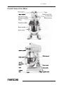
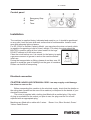
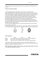
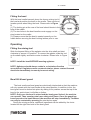
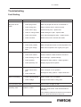
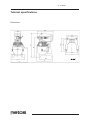
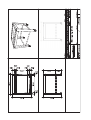
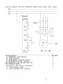
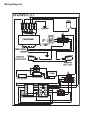
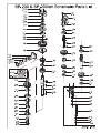
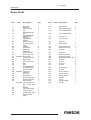
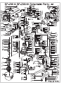
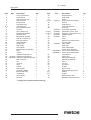
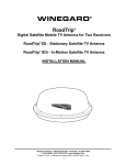
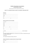
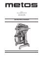
Mixer Metos Marine SP-200X 220-230/1/60 Hz fixed bowl guard Instruction manual Contents Read before you operate the machine .............................................................. 3 Overall View of the Mixer .................................................................................... 4 Control panel 5 Installation............................................................................................................ 5 Electrical connection 5 Installation 6 Operating instructions ........................................................................................ 6 Before using the mixer 6 Safety at work 6 Correct use of the mixer 7 Tool selection 7 Fitting the bowl 8 Operating ............................................................................................................. 8 Fitting the mixing tool 8 Bowl lift & bowl guard 8 Controls 9 Timed operation 9 Untimed operation 9 Speed selection 9 Attachments ......................................................................................................... 10 Cleaning Instructions .......................................................................................... 11 Care of the mixer 11 Maintenance ......................................................................................................... 11 On regular bases 11 On an annual bases 12 Gear oil renewal 12 Gearbox lubricant 12 Planetary unit lubricant 12 Troubleshoting..................................................................................................... 13 Fault finding 13 Teknical spesifications ....................................................................................... 14 Wiring Diagram .................................................................................................... 17 Spare Parts........................................................................................................... 19 31.12.2009 Read before you operate the machine It is important to read this manual before operatating the machine. This mixer is designed as a safe and efficient food processing appliance as long as it is used in accordance with the instructions in this manual and is properly maintained. Tek the following precautions in order to operate the mixer safely. l All operators should be at least 18 years old and adequately trained and supervised. Also, they should read and fully understood the instructions in this manual. l Owner should not let customes, visitors or other unauthorized people come in contact with this machine. l Do not wear loose clothes or rings while operating, and keep hands, hair and clothing away from the moving parts. l NEVER use an extension cord to connect electrical power. l Make sure the safety guard is closed and the bowl is lifted to right the position before operating. l NEVER reach into the bowl when the mixer is running. l NEVER place your hand or any kitchen utensil in the bowl whilst the mixer is in operation. l When mixing product always follow the recommended agitator and speed settings according to the capacity chart. l STOP the mixer before changing speed. l STOP the mixer before removing or installing attachments into the hub. l NEVER put your hand and finger into the feed chute when using any mixer attachment, including VH-12 Meat Mincer and V99S Vegetable Slicer. Always use the pusher plate with attachment. l Always UNPLUG before cleaning or doing any maintenance operations. l DO NOT hose down or pressure wash any part of the mixer. l NEVER bypass, alter or modify this machine. Doing so may create hazard and will void warranty. 3 31.12.2009 Overall View of the Mixer 4 31.12.2009 Control panel A B C Emergency Stop Start Timer Installation The machine is supplied factory lubricated and ready to run. It should be positioned on any solid, level and non-skid work surface that is nonflammable. Install in work area with adequate light and space. For SP- 200HI or Smaller Capacity Model, you may place the mixer on bench which is capable of supporting a load of mixer’s weight. For safety, the mixer should be BOLTED in position using all four holes located in the legs. DO NOT attempt to lift the mixer alone. Clean the mixer before use. It is normal for the factory to apply a generous amount of grease in and on the machine before initial use. During the transportation or fitting, please do not lean over 35 degree to avoid the gear oil leaking from the gear oil container. Please use forklift to transporting. Electrical connection CAUTION: NEVER USE EXTENSION CORD. Low amp supply could damage the mixer or cause a fire. Before connecting this machine to the electrical supply, check that the details on the rating plate (located on the rear of the machine) correspond to the details of your electrical connection. The mixer is supplied with a trailing lead fitted with a molded plug. If the style of plug is unsuitable for the socket you plan to use, the plug must be cut off and replaced with an appropriate plug. Machines are fitted with a cable with 3 wires: Yellow: Earth/Ground Brown: Live, Blue: Neutral, Green/ 5 31.12.2009 Installation The mixer should be plugged into a switched socket which isolates all poles and has a minimum contact clearance of 3mm and located close to the mixer for use in an emergency and to facilitate servicing. The machine must be incorporated into a potential equalization system. The leakage current for this appliance is no greater than 1 mA/KW. If the electrical supply cable to the machine becomes damaged, it must be replaced by a specifi cation or higher and suitable for the Mixer’s motor load. The ground wire is fi xed to the machine and this connection must be kept intact. CAUTION: The mixer MUST be grounded. The minimum requirement for all electrical equipment is correct operation between air temperature of +5 °C and +40°C. Electrical equipment is capable of operating correctly when the relative humidity does not exceeding 95% at a maximum temperature of +40°C. Electrical equipment is capable of operating correctly at altitude up to 1000m. Electrical equipment is designed to withstand to protected against the effects of transportation, and storage temperature within a range of -25°C to +55°C and for short periods not exceeding 24h at up to +70°C. Protection class IP54. Operating instructions Before using the mixer Before using the mixer, ensure that all users are familiar with the correct operation of the machine. In particular, care should be taken to ensure that the bowl and mixing tools are correctly fi tted and that the bowl guard is in position prior to starting the machine. Safety at work NEVER place your hand or any kitchen utensil in the bowl whilst the mixer is in operation. Keep hands, hair and clothing away from moving parts. Isolate the machine from the electrical supply by removing the plug from the socket before cleaning, servicing or adjusting any parts or attachments. 6 31.12.2009 Certain operator notice advising about the safe use of this mixer is attached to the machine. Correct use of the mixer It is the responsibility of the operators to use the mixer correctly within the recommended limitations. Always follow the instructions on the side of the machine when changing gear. If the motor labors, please stop the machine and reduce the size of the mix immediately. Damage resulting from improper use is will void the warranty. For operator safety, the machine is fitted with a bowl guard which is electrically interlocked to ensure that the mixer cannot operate unless the guard is correctly positioned and the bowl is raised. Excessive force used to open and close the bowl guard may damage the electrically interlocker, and will void the warranty. For additional safety, the mixer has a no volt release feature which means that in the event of a power failure, the machine will only restart after the control button has been pressed again. This arrangement ensures that when the supply is restored, the machine cannot restart on its own. Careful handling of bagged products by minimizing the height above the bowl base from which they are poured. Careful slitting of bags in the lower part of the bowl to allow dust free discharge of flour. Use temporary bowl covers to minimize openings through which flour many escape. Tool selection Beater: Dough Whisk: Beater Hook Whisk Firm mixes such as light pastry, cakes, biscuits, icings, fillings etc. Hook: Heavy mixes such as dough, pie pastry etc. Light mixes such as whipped cream, mayonnaise, egg whites etc. The beater, whisk and spiral dough hook are tools for the work implied by their names. Do not use the beater for dough making or the whisk for anything other than whisking, aerating or mixing light mixtures. NOTE: Always wash agitator with mild soap and apply light quantity of mineral oil to planetary shaft after cleaning. 7 31.12.2009 Fitting the bowl With the bowl cradle lowered, place the chosen mixing tool in the bowl and position the bowl on the cradle. There are three location points when fitting the bowl. Please refer to Figure 2: (1) The locking pin at the rear of the bowl should locate in the hole of the cradle. (2) The two holes in the bowl handles must engage on the pins located on the cradle. (3) Please ensure that the bowl is seated correctly on the cradle before securing the bowl locking latches prior to use. Operating Fitting the mixing tool Slide the bayonet fitting of the agitator onto the drive shaft and twist clockwise to secure it in position. To remove the agitator, slide the tool up the shaft slightly and twist counter clockwise. Please refer to Figure 3. NOTE: Install the bowl BEFORE inserting agitators. NOTE: Agitators should always rotate in a clockwise direction around bowl. If agitators move counterclockwise, please contact licensed electrician immediately to remedy incorrect wiring. Bowl lift & bowl guard The bowl cradle and bowl guard are electrically interlocked so that the machine will only operate with the bowl cradle at the raised position. In addition to this, the bowl guard must be locked into place by sliding it into position across the top of the bowl to the point where it will slide no further. NOTE: Only once the bowl is raised and the bowl guard locked, the machine can operate. Thus ensuring total user safety at all times. Once the guard has been opened or the bowl lowered, the machine will stop immediately. The Mixer can only be restarted by pressing the start button again. During the mixing process, additional ingredients can be added by the chute located on the right hand side of the bowl guard 8 31.12.2009 . Controls The Timer (C) is arranged to automatically stop the machine after the selected interval. An untimed position is provided for manually controlled mixing cycles. Before starting the mixer it is necessary to set the mixing duration or select the manual position – the mixer will not operate in the 0 position. Timed operation For timed operation turn the Timer Knob (C) to the desired time (duration is marked from 1 to 15 in graduations of one minute) and then press the Green Start Button (B) to start the mixer. After the timed period you set, the mixer will stop automatically. If it is necessary to stop the mixer before the end of the timed period, press the Red Stop Button (A). Untimed operation If you wish to manually control a mix, select the untimed mode by moving the Timer Knob anti-clockwise until it stops. Speed selection Before changing speeds, the mixer must always be STOPPED first. The necessary speed can then be selected before restarting the machine by pressing the Green Start Button. The speed selected depends largely on the quantity and consistency of the ha always started at the lowest speed and product. It is recommended t t mixing is 9 31.12.2009 progressively increased to the desired se"ng . In an emergency situa'on always use the Red Emergency Stop Bu-on to stop the machine . IMPO RTA NT: W he n mixi ng prod ucts a lways fo llow t he reco mme nded agitato r a nd s peed seL ng . The mixer is equipped with a motor overload protec'on . If the mixer shuts off during opera'on reduce the batch size and wait 2 mi nutes . Press t he sto p buYo n t he n press t he , sta rt buYo n. For heavier loads the mixer should not run longer than 15 minutes without pausing for a , cool down period of at last 15 minutes or more before resuming mixer. For lighter loads the mixer should not run longer than 30 minutes without pausing for a cool down period of at last 30 minutes or more before resuming mixer. Attachments The ranges of a-achments that can be operated from the A-achment Hu b are listed below. When using an a-achment lu bricate , the Drive St ud ( D) using a food quality grease or oil . To fix to the mixer refer to Fig ure 4 . Release the T humbsc rew (G) and slide the shal of the a-achment into the hu b ensuring that the Drive St ud ( D) engages in the socket within the hu b. Rotate the a-achment to line up the Locaoo n Peg ( E) with its ma'ng hole in the hu b and push firmly Fig ure 4 home . Tighten thum bscrew to secure . CAUT IO N: O nly fit aYac hme nts w he n t he mixe r is staoo na ry a nd neve r w he n it is o pe rao ng . Do not use aYac hme nts w he n mixi ng . The recommended speed range for the a-achments availa ble is shown in ta ble below. 10 31.12.2009 NOT E: Make sure the bowl is up and the bowl guard is closed, otherwise the mixer will not funcon . Care of the mixer CAUT IO N: A LWAYS DISCO NNECT O R UNPLUG T HE ELECT RICA L POW ER FRO M T HE MIX ER BEFO RE C LEA NING . The mixer is designed for simple maintenance carried out by operators . It may be necessary from me to me to apply a li³le Vaseline and oil to the rods on which the bowl cradle slides . If so, use a li³le food quality lu bricant, ensuring that there is no excess oil that could contaminate the food mix . Clean the mixer thoroughly a·er use . A·er isolang the machine from the electricity supply, the body should be wiped down with a damp cloth . Do not s pray t he mac hi ne wit h o r i mme rse it i n wate r. Do not forget to clean the rear of the machine and do not a llow t he rea r ve nts to beco me bloc ked as t his may res ult i n ove rheaÎ ng . Pay parcular a³enon to the bowl pins and any surrounding areas of the cradle to prevent the accumulaon of mix, as this could prevent correct locaon of the bowl . For the same reason ensure that the beater sha· and each of the sockets on the tools are cleaned thoroughly. The bowl and tools should be washed in hot soapy water, rinsed and dried before being put into storage . Do not was h t he agitato rs i n a dis hwas he r, as t he po lis hed fi nis h wi ll be adve rse ly affected by t he dis hwas hi ng c he mica ls . It is recommended that any service or maintenance work must be carried out by a trained technician or electrician . CAUT IO N: A LWAYS DISCO NNECT O R UNPLUG T HE ELECT RICA L POW ER FRO M T HE MIX ER BEFO RE DO ING MA INT ENA NC E. Regular maintenance is necessary on all machines if they are to remain in good working d con ion . It is strongly recommended that all maintenance must be carried out by trained technicians from an appointed distri butor. On regular bases Clean the machine thoroughly a·er use and lu bricate the rods with Vaseline or lu bricaon oil which the bowl cradle slides . A·er cleaning the beater sha·, please wipe and lightly lu bricate the beater sha· with Vaseline to prevent rusng . (S EE CA RE O N YO UR MIX ER) 11 31.12.2009 On an annual bases • • • • • Check that all bolts are tight and bowl guard secure. Carry out on a more frequent basis if machine is arduously used. After replacing the parts by technicians, please screw back tightly with anti-leaking coat to avoid the gear oil leaking after replacement. Do not insert any object into the air vent of motor or into the bowl. Please unplug while not using the mixer. Gear oil renewal Please unscrew and leak the oil from the indicated oil leaking hole . Aóer finishing the ï leaking, re screw back ÷ghtly with the an÷ leaking coat on the screw. Fill the gear oil to the ï ï indicated re fill oil hole . We recommended that this service or maintenance work must be ï carried out by trained technicians. Gearbox lubricant In terms of the rest model from S P 00 to S P 0 HI, please refill the lu bricant inside the ï1 ï6 gear box every 5 years . We recommended that this servicing or maintenance work must be carried out by trained technicians . CAUTION: Please use either Mobil lubricant “XHP 222” or Brugarolas “GRASA AGUILA PLEX 2-BOLSA” Planetary unit lubricant Please add only 2 pumps of grease to the planetary grease fi ng once a year. In case there is a strange noise coming from the planetary unit, please reapply grease to the planetary unit by using the grease gun . We recommended that this servicing or maintenance work must be carried out by trained technicians . CAUTION: Please use TACBECON grease “GL$210” to lubricate the pla neta ry unit. 12 31.12.2009 Troubleshoting Fault finding Fault Check Possible reson and action required No power to the mixer 1. Check plug socket Mixer not pluged into alive or not switched on 2. Check wiring plug Plug incorrectly wired - rewire correctly 3. Check fuse in plug Possible faulty fuse - replace fuse 4. Check or change cable Cable damaged or split - replace cable 5. Check microswitch Limit switch damaged or faulty - replace switch 6. Check overload Reduce load, wait 2 minutes and restart 1. Check bowl guard/lift Mixer will not operate with guard open 2. Check timer position Mixer will operate on timer or manual position only 3. Check gear change lever Mixer will not operate if out of gear-put in gear Mixer falls to operate Mixer becomes noisy 1. Check bowl and tools Mixer loses power Ensure that bowl and tool are correctly seated 2. Check work surface Uneven surfaces create excessive resonance 3. Check bearing for wear Worn bearings - replace bearings 4. Check gearbox Damaged or faulty gearbox - replace gearbox 5. Check planetary unit Reapply high-pressure grease 1. Check capacity Overload - reduce the load 2. Check transmission gear Gear damaged or worn gearbox Damaged or faulty gearbox - replace shaft bias 3. Check shaft bias Motor overheating 1. Check capacity/speed Refer to table 2 and 3 for details 2. Check voltage Voltage should relate to rating plate Oil on planetary shaft Check oil seal Worn oil seal - change oil seal Mixing tool stuck on planetary shaft Planetary shaft twisted or bent - change the shaft Check planetary shaft bent, unclean or rusted Planetary shaft rusted - clean with descaler for derusting Turn planetary shaft anti-clockwise to meet square groove, gently knock down mixing tools 13 31.12.2009 Teknical spesifications Dimentions 14 Wiring Diagram 31.12.2009 Spare parts Spare Parts Item 3 4 69 70 71 72 90 91 92 93 94 95 96 97 98 99 100 101 102 103 104 105 106 107 108 109 110 111 112 113 114 115 Part Description level drive gear:35T washer-thrust ball bearing:#6201Z ball bearing:#6203Z retainer-twin bearing cap-bearing retainer lead-in oil pad to guard gainst busk roll pillar spring slice gear-slow speed:46T gear-bevel:46T gear-clutch:29T 5510035 busk-clutch level key:6x6x27 busk-clutch gear-clutch:38T heel ball bearing:#6205Z oil ring:28x22x3 guard-oil busk 5510075 seal-oil:TC 35x52x10 nut-stop shaft-driven level key:6x6x45 level key:5x5x27 sleeve-clutch 5510038 yoke-shifter assy. incl. 111-116, 212213 nut-stop rod-shifter guide retainer-spring spring-shifter yoke plunger-shifter yoke Qty Item 1 Part Description Qty 116 yoke-shifter 1 2 2 117 118 ball bearing:#6201 worm wheel 50HZ 2 1 1 118 worm wheel 60HZ 1 1 119 as item 117 1 120 c-ring:stw-19 2 1 1 121 122 gear:24T spacer-busk 1 1 8 8 1 123 124 125 level key:5x5x15 shaft-master:15T nut-stop 1 1 1 1 1 1 1 1 1 1 1 126 127 128 129 130 131 132 133 gear:32T level key:5x5x10 level key:5x5x10 sheft-transmission:15T nut-stop screws nut-stop screws 1 1 1 1 1 6 2 3 2 1 1 182 183 210 ball bearing oil seal anti-oil spacer 1 1 1 2 1 1 2 1 1 211 212 213 214 215 263 anti-oil spacer spring washer washer c-ring spring washer spacer 1 1 1 1 1 1 1 1 2 2 2 19 31.12.2009 Spare parts Item 1 2 3 4 5 6 6_1 7 8 9 10 11 12 13 14 15 20 21 22 23 24 25 26 26 28 29 31 32 33 34 35 36 37 38 39 Part Description cover-transmission control panel evel drive gear:35T washer-thrust thumb screw hub-attachment anti-oil spacer plug-attachemnt hole nut-stop pinion-beater:19T ball bearing:#6203Z planetary hole ball bearing: #6204Z seal-oil:TC 25x47x10 level key:5x5x20 shaft-planetary steady hook bowl cradle escort plank behind interlock guarding base screws Capacitor 230/1/50 Hz 5510002 Capacitor 230/1/60 Hz 5510005 Contactor (Ue230-380-440) wire connector net nut-stop sring washer pillar-middle pin-spring (3MM) Bowl lift rod assy: rod-bowl lift arm-bowl lift pin:5x30 Qty 1 1 1 2 1 1 1 1 1 1 1 1 1 1 1 1 2 1 2 1 1 4 1 1 1 1 1 2 1 3 1 1 1 1 1 Item 40 43 44 45-48 45 46 47 48 49-49_1 50-50_1 51 52 53 54 55 57 58 59 60 61 62 63 64 65 66 67 73 74 75 75_1 75_2 76 78 Part Description height adjuster touch shaft spring 5510010 Gear shift level assembly wrench shaft-wrench cover-transmission shaft-bias 5510038 york shifter assembly 5510020 start button, green, assy 5510025 emergency stop button assy 5510030 platinium switch 5510034 clutch cover behind cover-transmission engrave plate 5510056 micro switch fixed seat case transmission spring shock absorber 200062H-B motor compl. 230/1/50Hz 200062H-X motor compl. 230/1/60Hz motor shaft ** motor coil ** ball bearing #6203Z ball bearing #6203Z worm ** nut-stop pin-spring oil-plug above cover safety guard spring lock washer screws plastic slide sheath planetary internal gear:63T ** voltage to be indicated when ordering 21 Qty 1 1 1 1 1 1 1 1 1 1 1 1 1 1 1 1 2 1 1 1 1 1 1 1 1 1 1 1 1 1 1 1 2 2 1 1 31.12.2009 Spare parts Item 79 80 81 82 83 85 86 87 88 119 134 134 135 135 136 137 138 139 140 141 142 143 144 145 146 148 149 150 151 152 153 154 155 156 157 158 160 Part 5510056 5510065 5510070 3434278 Description fixed slice pin front interlock guarding screws screws micro switch screws dowel screw nut-stop ball bearing #6201Z transformer 24V 60 Hz transformer ** overload relay 60 Hz overload relay ** fuse 1A fuse fixture front feet rubber mats back feet rubber mats spring washer screws screws cover for cradle washer washer spring nut screws spring washer screws screws anti-water spacer nut sleeve pin S/S ball spring spring washer Qty 1 1 1 6 6 1 2 2 2 1 1 1 1 1 1 1 2 2 4 4 2 1 2 2 2 2 6 6 4 4 1 4 2 1 2 2 4 Item 161 162 163 164 165 167 168 169 171 172 173 174 175 176 177 178 179 180 181 182 183 184 185 186 187 188 189 190 191 192 193 195 196 197 198 Part Description nut nut spring washer plastic tube nut screws screws nut screws spring washer screws screws 5510052 timer assy.w/knob 60 Hz incl. 175,176,177,178 timer ** screws spacer connection screws screws screws ball bearing oil seal upper cover for column screws washer barcket for micro switch knob for bowl clamp washer touch mass (L type) cover plate bowl lift cam power line circular washer /whip screws spring washer mounting plate Qty 4 2 1 1 2 12 4 4 2 4 4 4 1 1 4 1 1 4 1 1 1 1 1 2 4 1 2 8 1 1 1 1 1 5 1 1 ** voltage to be indicated when ordering 23 31.12.2009 Spare parts Item 199 200 201 202 203 204 205 206 207 208 209 216 217 218 219 220 221 222 223 224 225 226 227 228 229 230 231 233 236 237 238 239 240 241 242 243 Part Description anti-oil spacer screws knob for gear shift level level key spring washer screws net screws spring washer nut washer grease fitting grease tube washer strain relief nail cable line cable line cable line cable line nut strain relief screws nut nut screws fixture for capacitor pin fixure fixure fixure pin plastic washer screws screws screws Qty 1 4 2 2 2 2 1 4 4 2 2 1 1 4 1 2 1 1 1 1 2 2 3 2 1 1 1 2 1 1 1 1 1 1 1 2 Item 244 245 246 247 249 250 251 252 253 254 255 256 257 259 260 264 Part Description nut screws nut screws washer rubber o-ring pin washer nut nut washer screws tetragon washer anti-oil spacer cover rubber o-ring Qty 8 1 1 9 1...5 2 2 1...5 2 1 1 1 4 1 1 1 ** voltage to be indicated when ordering 25