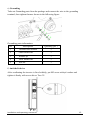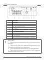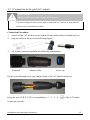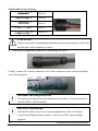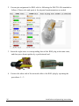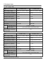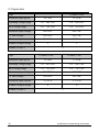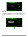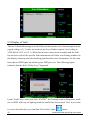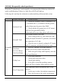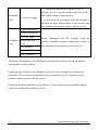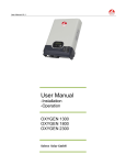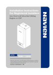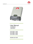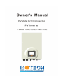
1
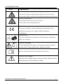
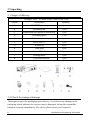
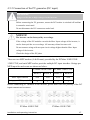
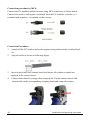
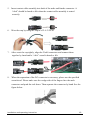
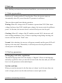
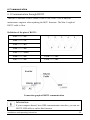
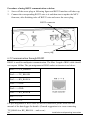
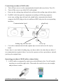
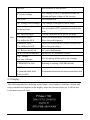
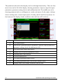
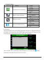
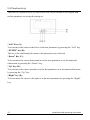
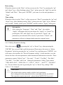
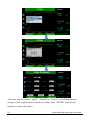
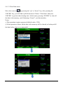
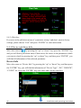
Table of Contents 1 About this instruction .................................................................................. 4 1.1 Validity ........................................................................................... 4 1.2 Target group ................................................................................... 4 1.3 Retention of the instruction............................................................. 4 1.4 Index of installation and startup ..................................................... 4 1.5 Regulations ..................................................................................... 5 1.6 Safety rules ..................................................................................... 5 2 Safety instructions and regulations ............................................................ 6 2.1 Technical rules ................................................................................ 6 2.2 Intended use.................................................................................... 6 2.3 Accident prevention regulations...................................................... 6 2.4 Symbols Used .................................................................................. 7 3 Unpacking ..................................................................................................... 8 3.1 Scope of delivery ............................................................................. 8 3.2 Check for transport damage ........................................................... 8 4 Installation .................................................................................................... 9 4.1 Select an appropriate place ............................................................. 9 4.2 Ambient conditions ......................................................................... 9 4.3 Mounting position ..........................................................................11 4.4 Installation procedure ....................................................................11 4.5 Electrical connection ......................................................................14 4.5.1 Connection to the grid (AC output) ............................................................15 4.5.2 Connection of the PV generator (DC input) ...............................................17 Installation and operating instruction 1 5 Start-up ....................................................................................................... 21 5.1 Start-up procedure ........................................................................21 5.2 Set key parameters.........................................................................21 5.3 Automatic shutdown / startup ........................................................22 6 Communication .......................................................................................... 23 6.1 Communication through RS232 .....................................................23 6.2 Communication through RS485 .....................................................24 6.3 USB................................................................................................27 7 Safety protection ........................................................................................ 28 8 Technical data ............................................................................................ 29 8.1 AC output data ..............................................................................29 8.2 Input data ......................................................................................30 8.3 General data ..................................................................................31 8.4 Cable requirement .........................................................................32 9 Operating .................................................................................................... 33 9.1 Overview ........................................................................................33 9.2 LEDs ..............................................................................................34 9.3 Display ...........................................................................................35 9.4 Function keys .................................................................................38 9.4.1 Check parameters of the generated energy .................................................39 9.4.2 Check parameters at AC and DC side ........................................................40 9.4.3 Parameter setting ........................................................................................42 9.4.4 Device and Error Info .................................................................................46 9.5 Display of fault...............................................................................48 10 FAQ (Frequently asked questions) ......................................................... 49 2 Installation and operating instruction 11 Service and maintenance ......................................................................... 51 12 Contact ...................................................................................................... 52 Installation and operating instruction 3 1 About this instruction General notes Thank you for choosing a MOTECH inverter! MOTECH inverter converts the direct current from your solar system into grid-compliant alternating current. When you choose MOTECH inverter, you opt for reliable and powerful technology. 1.1 Validity This instruction describes the installation, startup and maintenance of MOTECH PVMate 10NE/12NE/15NE/17NE. 1.2 Target group The inverter can only be installed by qualified electricians who will register you with the utility company and have your photovoltaic installation approved by the grid operator. If you encounter any problems, read this instruction at first before calling the service. 1.3 Retention of the instruction All documentation and accessories must be kept and available at all times. 1.4 Index of installation and startup 1. Safety instructions and regulations: see 1.1, 1.2, 2.1, 2.2, 2.3 2. All the included accessories: see 3.1 3. Inspection of transport damage: see 3.2 4. Installation preparation: see 4.1, 4.2, 4.3 5. Installing procedure: see 4.4 6. Connection to the grid: see 4.5.1 7. Connection to PV generator: see 4.5.2 8. Startup: see 5.1 9. Key parameter setting: see 5.2 10. Communication by RS485: see 6.2 4 Installation and operating instruction 1.5 Regulations Type Normative reference VDE 0126-1-1, VDE-AR-N 4105, BDEW, PVMate 10NE/12NE/15NE/17NE G59/2, G83/1, RD 1663, ENEL Guide, EN 50438, AS4777.2/.3, EN 62109-1 1.6 Safety rules The safety precautions and general information as follows are used in this instruction: DANGER! Failure to observe a warning indicated in this instruction will result in serious injury or death. Iii WARNING! Failure to observe a warning indicated in this instruction may result in serious injury or death. CAUTION! Failure to observe a warning indicated in this instruction may result in minor or moderate injury. NOTICE! Failure to observe a warning indicated in this instruction may result in property damage. Information Information provides tips which are valuable for the optimal installation and operation of the inverter. Installation and operating instruction 5 2 Safety instructions and regulations 2.1 Technical rules Installation must be suited to the on-site conditions and comply with local regulations and technical rules. 2.2 Intended use The inverter is designed according to the safety rules. However, improper use, move, personal maintenance or modification may result in injury, death and property damage. MOTECH is not responsible for the loss and invalidate these warranty claims. 2.3 Accident prevention regulations 1. Only qualified electricians who have read and fully understood all safety information contained in the instructions can install, maintenance and repair the inverter. 2. The inverter must only be operated with PV generator. Do not connect any other source of energy to it. 3. Be sure that the inverters connect to the ground in order to protect property and personnel safety. 4. Before opening the housing, the inverter must be disconnected with the grid and PV generator; while you must wait at least five minutes to allow the energy stored in capacitors to be fully discharged. 5. It is not possible to ground any of the terminals of the PV modules. However, it is compulsory to ground all conductive materials, e.g. the mounting system to comply with the general codes for electrical installations. 6. Password protection is given for protection function U >, (According to VDE 4105, cl. 6.3). 6 Installation and operating instruction 2.4 Symbols Used Icon Explanation Beware of high electrical voltage and high operating current. The inverter operates at high voltage and current. All work on the inverter must only be carried out by skilled and authorized electricians. Beware of hot housing. The housing of the inverter may become hot. Avoid contact with it during operation. CE mark. The inverter complies with the fundamental requirements of the Guideline Governing Low-Voltage and Electromagnetic Compatibility. Certified safety The inverter fulfills the requirements of the Equipment and Product Safety Act in Europe. Capacitor discharge. Do not disconnect DC input or AC output connectors until 5 minutes after the disconnection of all power sources. Refer to the instruction which accompanies the inverter. Caution, risk of danger Important information, failure to observe them indicated in this instruction may result in injury or death. Installation and operating instruction 7 3 Unpacking 3.1 Scope of delivery Fittings List of PVMate 10NE/12NE/15NE/17NE Object Description Quantity A MOTECH inverter 1 pcs B Mounting rail 1 pcs C Installation and operation instruction 1 pcs D Grounding parts 1 Set E AC female connector 1 pcs F Screw M5×12 1 pcs G Washer φ6 6 pcs H Wall plug 5 pcs I Screw ST6×50 5 pcs J Sealing insert 3 pcs K Cord end terminal 5 pcs 3.2 Check for transport damage Thoroughly inspect the packaging upon delivery, if you detect any damage to the packaging which indicates the inverter may be damaged, inform the responsible transport company immediately. We will be glad to assist you if required. 8 Installation and operating instruction 4 Installation 4.1 Select an appropriate place DANGER! Danger to life due to fire or explosion. Despite careful construction, electrical equipment may cause fire. Do not mount the inverter on flammable materials. Do not install the inverter in areas where there store highly flammable materials. Do not install the inverter in areas where there is a risk of explosion. CAUTION! The housing may become hot during operation. Risk of burns! Mount the inverter in areas where it cannot be touched unintentionally. Wait approx. 30 minutes until the housing has cooled down before proceed to disassembly the inverter. 4.2 Ambient conditions 1. The area where the inverter mounted is as dry as possible. 2. Ensure good access to the inverter for installation and possible service purposes. 3. Be sure that inverter is out of the children’s reach. 4. Provide better ventilation for the inverter to ensure that heat is dissipated quickly. 5. Ensure the following minimum clearance around it: Direction Minimum clearance(mm) above 200 below 500 sides 300 ambient dimensions of one inverter Installation and operating instruction 9 ambient dimensions of a series of inverters 6. When installing the inverter on the wall of a building, please ensure the wall is a concrete wall and not wooden wall. In the event that inverter must be mounted on wooden wall, please add the heat insulation material between the inverter and the wooden wall. 7. If you have to install the inverter on the wooden wall, we don’t recommend self-tapping screws and wall plugs; instead, please use the M6 bolt, nut, spring washer each 5pcs. The bolt should be 10mm longer than thickness of wooden board for nut fixing. The wooden board should be above 15mm and of log material to meet the strength requirement when hanging. 8. Do not expose the inverter to direct sunlight, in order to avoid power reduction caused by excessive heating. The ambient temperature keeps below 45℃ will guarantee the inverter working in optimal status. 9. Don’t put any things on the inverter. Do not cover the inverter. 10. Before cleaning, disconnect the inverter separately with the grid by cutting off the AC breaker and with the PV generator by cutting off the DC breaker in order to exclude the danger of electric shock. Using a soft, dry cloth to clean it. Never use corrosive, solvent-containing or abrasive cleaners or polishes. 10 Installation and operating instruction 4.3 Mounting position 1. Mount the inverter vertically or tilted backward by Max. 15°. 2. Never mount the inverter forwards. 3. Never mount the inverter horizontally. 4. Never install the inverter with a sideways tilt. 5. Mount at eye level to makes it easier to operate and read the display. 6. The electrical connection area must point downwards. 4.4 Installation procedure a) Drilling holes Drill five holes (φ10) at the selected installation position. The space of the holes is shown as following figure. Keep drill vertical to the wall, and don’t shake the drill to avoid holes tilt. The depth of the holes must be the same and in the range of 55 ~ 60mm. After removing dust in the five holes, measure the net depth. WARNING! Risk of injury due to the incorrect mounting holes. Before inserting wall plugs, measure the depth and distance of the holes. If the measure values don’t meet the installation requirement, redrill the holes. Installation and operating instruction 11 b) Mounting bracket After drilling holes in the wall, place five wall plugs into the holes vertically. Put washers through the self-tapping screws that came with the inverter, and then attach the mounting rail to the wall. c) Hanging the inverter Hang the four holes of the inverter onto the four hooks of the mounting rail downwards slightly as following figure. d) Positioning check After the inverter is hung on the mounting rail, check whether the four holes of the inverter match the four hooks of the mounting rail reliably. If there is anything wrong, please dismount the inverter and relocate. 12 Installation and operating instruction e) Grounding Take out Grounding parts from the package and connect the wire to the grounding terminal, then tighten them as shown in the following figure. Grounding parts information: No Description Quantity( pcs ) 1 Serrated lock washer 1 2 Cable socket M5 1 3 Washer φ5 1 4 Lock washer M5 1 5 Nut M5 1 f) Anti-theft device After confirming the inverter is fixed reliably, put M5 screw with φ6 washer and tighten it firmly with screw-driver Torx 25. Installation and operating instruction 13 4.5 Electrical connection component Description A DC-switch B DC Input terminal of route A C DC Input terminal of route B D Grounding E USB interface (only for updating PCU firmware) F Grid connection interface G Ethernet interface H RS485 interface I RS232 interface (only for updating MCU firmware) Information: 1. After the inverter has been mounted firmly, the electrical connection can begin. 2. Make sure Max. Open circuit voltage and short circuit current of the PV modules accord with input spec of the inverter. 3. Choose the appropriate cable model; see “8.4 Cable requirements”. 4. Before doing the electrical connection, both AC and DC end must be disconnected with all power sources. 14 Installation and operating instruction 4.5.1 Connection to the grid (AC output) DANGER! Danger to life due to high voltages in the inverter. You must safeguard each inverter with an individual AC breaker in order that the inverter can be disconnected safely. Connection Procedure: 1. Switch off the AC breaker secure against being inadvertently switched back on. 2. Strip the cable as shown in the following figure: 3. AC female connector includes the following components: Terminals adapter body screw cap Put the wires through screw cap, adapter body of the AC female connector. Keep the wire N, R,S, T, PE corresponding to 1、2、3、4、 of the AC female connector correctly. Installation and operating instruction 15 Match table of wire & hole: 1 N Wire N 2 R Wire R 3 S Wire S 4 T Wire T PE Wire PE CAUTION! Please ensure the corresponding relationship between the polarity of the wire and the hole of the terminal is correct. 4. Screw these components tightly after connecting the wires. Finally, connect AC female connector to AC male connector on the inverter and then screw them together. Residual current protection Residual current detection and monitoring unit inside, it’s not necessary to install a RCD or RCM outside Risk of DC injection high Pull the PE and N wires to the corresponding holes of the AC female connector and tighten them reliably, or the error of DC injection high happens. 16 Installation and operating instruction 4.5.2 Connection of the PV generator (DC input) DANGER! Danger to life due to high voltages in the inverter. Before connecting the PV generator, ensure the DC breaker is switched off and that it cannot be reactivated. Do not disconnect the DC connectors under load. NOTICE! The inverter can be destroyed by overvoltage. If the voltage of the PV modules exceeds the Max. Input voltage of the inverter, it can be destroyed due to overvoltage. All warranty claims become void. Do not connect strings with an open circuit voltage higher than the Max. Input voltage of the inverter. Check the design of the PV plant. There are two MPP trackers (A & B route) provided by the PVMate 10NE/12NE/ 15NE/17NE, and each MPP tracker provides multiple DC input interface. Strings per MPP input for each route are shown as below. PVMate 10NE/12NE PVMate 15NE/17NE Route A Route B Route A Route B Max. input current 22A 11A 22A 22A Strings per MPP input (A/B) 4 1 3 3 Before connecting PV modules to the inverter, please make sure the polarity of the DC input connectors is correct. PVMate 10NE/12NE Installation and operating instruction PVMate 15NE/17NE 17 Connection procedure by MC4: Connect the PV modules and the inverter using MC4 connectors as shown below. Connect the positive and negative terminals from the PV modules to positive (+) terminals and negative (-) terminals on the inverter. Connection Procedure: 1. Switch off the DC breaker and secure against being inadvertently switched back on. 2. 3. Strip the cable as shown in following figure. Insert striped cable into contact barrel and insure all conductor strands are captured in the contact barrel. 4. Crimp contact barrel by using a hex crimping die. Put the contact barrel with striped cable in the corresponding crimping notch and crimp the contact. 18 Installation and operating instruction 5. Insert contact cable assembly into back of the male and female connector. A “click” should be heard or felt when the contact cable assembly is seated correctly. 6. Wrest the cap by using the torque of 2.6~2.9N.m. 7. After wrest the cap tightly, align the 2 half connectors and connect them together by hand until a “click” sound is heard or felt. 8. When the separation of the DC connector is necessary, please use the specified wrench tool. Please make sure the wedge side of the fingers face the male connector and push the tool down. Then separate the connector by hand. See the figure below. Installation and operating instruction 19 9. If input connector is not enough, adopt“ Y ”connector ( optional ) just as below: 10. Please use sealing caps for tight sealing of unplugged PV connectors. If using H4 connector, the operating procedure is similar to that of MC4 connector. DANGER! DANGER to life due to potential fire or electric shock. NEVER connect or disconnect the DC connectors under load. 20 Installation and operating instruction 5 Start-up After finishing mechanical and electrical installation, you can start up the inverter. 5.1 Start-up procedure Switch on AC breaker and the PV-load breaker. Then, the inverter starts up automatically when DC power from the PV generator is sufficient. There are three normal states during operation: Waiting: When DC voltage of the PV modules is greater than 250V (Min. input voltage) but lower than 300V (initial input voltage), the inverter waits for sufficient power. At this time, the inverter doesn’t work and feed power into the grid. Checking: When DC voltage of the PV modules exceeds 300V, the inverter will check feeding conditions at once. If there is anything wrong during checking, the inverter will turn into the “Fault” state. Normal: After checking, the inverter will operate normally and the green LED will light up at the same time. Meanwhile, it will feed power into the grid and show current power on the display. 5.2 Set key parameters Set language and safety regulations The default language showed on the display is “English”. Please set the language and safety regulations when you start the inverter for the first time and you will find how to set the parameters in the ninth chapter. Set date and time When you start the inverter for the first time or it doesn’t work for more than one week or longer, please reset the date and time to ensure right records. Installation and operating instruction 21 5.3 Automatic shutdown / startup When sunlight weakens gradually, DC voltage of the PV modules is less than shutdown voltage(220V), the inverter itself will stop working and won’t feed power into the grid; when sunlight strengthens gradually, DC voltage of the PV modules exceeds 250V, the inverter will automatically startup with the following steps “waiting, checking, normal”. Normally, the inverters will start-up in the morning and shutdown at the evening. Information: If the inverter is in “Fault” state, refer to the FAQ part in the tenth chapter. 22 Installation and operating instruction 6 Communication 6.1 Communication through RS232 The RS232 interface of the PVMate 10/NE/12NE/15NE/17NE is only for maintenance engineer when updating the MCU firmware. The Max. Length of RS232 cable is 10m. Definition of the pins of RS232: Pin1--------NC Pin2--------TX Pin3--------RX Pin4--------NC Pin5--------GND Pin6--------NC Pin8--------NC Pin7--------NC Pin9--------NC Connection graph of RS232 communication Information: If your computer doesn’t have DB9 communication interface, you can use RS232-USB cable to realize this function. Installation and operating instruction 23 Procedure of using RS232 communication as below: 1. Screw off the screw plug as following figure and RS232 interface will show up; 2. Connect the corresponding RS232 wire to it and then start to update the MCU firmware; after finishing, take off RS232 wire and screw the screw plug; RS232 connector screw plug 6.2 Communication through RS485 RS485 is used for multipoint communication. The Max. Length of RJ45 cable should not surpass 1000m. The pin assignment of RJ45 socket on inverter is as below: Pin1------- TX_RS485A Pin2-------TX_RS485B Pin3-------RX_RS485A Pin4-------GND Pin5-------GND Pin6-------RX_RS485B Pin7-------+7V Pin8-------+7V For pin assignment of RJ45 cable for RS485 connection, please check the user manual of the data logger for details. (General suggestion is to cross connecting TX_RS485A to RX_RS485A….and so on.) 24 Installation and operating instruction Connection procedure of RJ45 cable: a. Take off 8pcs screws on the communication board with screw driver Torx 20; b. Twist off the screw cap of the M12 cable gland; c. Eject out the sealing ring without hole, and insert the sealing ring with one hole; d. Put RJ45 cable through the components according to following sequence: screw cap, sealing ring with one hole, gland body, communication board; compress the RJ45 plug on the site and insert RJ45 plug into the corresponding interface; Communication board Sealing ring with one hole e. gland body screw cap Cover the communication board, tighten 8pcs screws and screw the cap by hand; Notes: there’re two kinds of sealing ring, one has no hole, the other has one hole; if no communication required, there’s no need to operate as above procedures; instead, just keep the original state. Operating procedure of RJ45 cable as shown below: 1. A RJ45 cable is composed by eight wires with different color. Cut off outside envelope to reveal the eight wires. Then make the end of every wire straight, and put them in order. Installation and operating instruction 25 2. Current pin assignment for RJ45 cable is following the EIA/TIA 586 standard as follows. Please refer and apply it for physical implementation as needed. 3. Insert the eight wires to corresponding slots of the RJ45 plug at the same time, and then press them together by a professional tool. 4. Connect the other end of the network cable to the RJ45 plug by repeating the procedures 1~3. 26 Installation and operating instruction 6.3 USB USB interface is specially designed for maintenance engineer to burn and update of PCU firmware. Operation procedure is as below: 1. Twist off the screw plug; 2. Connect USB cable; 3. Dial switch downwards; 4. Press reset button; 5. Dial switch upwards; 6. Start to update the PCU firmware; 7. Pull out USB cable; 8. Re-press reset button; 9. Twist on the screw plug; toggle switch USB interface reset button screw plug Installation and operating instruction 27 7 Safety protection We provide the following safety protection for you: 1) Overvoltage, undervoltage protection; 2) Overfrequency, underfrequency protection; 3) Over temperature monitoring; 4) Residual current monitoring; 5) Isolation fault detection; 6) Anti-islanding protection; 7) DC injection monitoring; 28 Installation and operating instruction 8 Technical data 8.1 AC output data PVMate 10NE PVMate 12NE Main voltage / range 400 V x 3 / 320 V ~ 460 V 400 V x 3 / 320 V ~ 460 V Grid frequency, nominal 50 Hz 50 Hz Main frequency / range 50 / 45~55; 60 / 55~65 50 / 45~55; 60/ 55~65 Nominal output power 10kW 12kW Maximum AC apparent 10 kW 12 kW Maximum output current 16 A 19.2 A Waveform True sine True sine Type power Power VDE-AR-N 4105 factor Other safety 0.85ind - 0.85cap >0.97 at 20% load, >0.99 at 100% load Total harmonic distortion < 4% at 100% load PVMate 15NE Type PVMate 17NE Main voltage / range 400 V x 3 / 320 V ~ 460 V 400 V x 3 / 320 V ~ 460 V Grid frequency, nominal 50 Hz 50 Hz Main frequency / range 50 / 45~55; 60 / 55~65 50 / 45~55; 60 / 55~65 Nominal output power 15 kW 17 kW Maximum AC apparent 15 kW 17 kW Maximum output current 24 A 25.8 A Waveform True sine True sine power Power VDE-AR-N 4105 factor Other safety Total harmonic distortion 0.85ind - 0.85cap >0.97 at 20% load, >0.99 at 100% load < 4% at 100% load Installation and operating instruction 29 8.2 Input data PVMate 10NE PVMate 12NE Maximum input power 10.3 kW 12.5 kW Operating voltage range 270 ~ 900 VDC 270 ~ 900 VDC MPP voltage range 270 ~ 780 VDC 270 ~ 780 VDC Maximum input voltage 900 VDC 900 VDC PV start voltage 290 VDC 290 VDC Maximum input current 22 A/11A 22/11 A Number of input strings 5 5 Type Number of MPPT Type 2 PVMate 15NE PVMate 17NE Maximum input power 15.5 kW 17.6 kW Operating voltage range 270 ~ 900 VDC 270 ~ 900 VDC MPP voltage range 270 ~ 780 VDC 270 ~ 780 VDC Maximum input voltage 900 VDC 900 VDC PV start voltage 290 VDC 290 VDC Maximum input current 2 × 22 A 2 × 22 A Number of input strings 6 6 Number of MPPT 30 2 Installation and operating instruction 8.3 General data Efficiency Maximum efficiency European efficiency Operating (standby) consumption Night consumption Environment Operating temperature range Maximum full power operating temperature without derating Relative humidity Maximum operating altitude above mean sea Mechanical data Electronics protection rating Cooling Inverter weight Noise level Dimensions (H × W × D) Features Topology Communication USB Built-in DC disconnect Display Certifications PVMate 10NE/12NE/15NE/17NE 97.8% 97.4% < 25W < 0.6 W -20°C ~ +60°C 45°C Maximum 98% 2000 m IP65 Controlled forced ventilation 50 kg < 50 dB(A) 760 × 500 × 180 mm TL RS485 no yes 5.9” LCD VDE 0126-1-1, VDE-AR-N 4105, G59/2, G83/1, EN 50438, AS4777.2/.3, EN 62109-1 Warranty Installation and operating instruction 5 years 31 8.4 Cable requirement Object PVMate 10NE Wire(R, S, T, N) AC conductor Max. recommended cable length (cables cross-section area power loss of 1% rated output power) 2 27.4m 2 38.4m 2 4 mm 6 mm PVMate 12NE 4 mm 22.8m Wire(R, S, T, N) 6 mm2 32m PVMate 15NE 4 mm2 18.3m Wire(R, S, T, N) 2 6 mm 25.6m PVMate 17NE 4 mm2 17.9m Wire(R, S, T, N) 6 mm2 25.1m PE at least as phase cables For AC cable, make sure the inside wire must be flexible and the each cross-section not less than above 6mm2. Avoiding too much power loss due to inappropriate cable model of DC input, please Choose AWG12 (4mm2, 4.75Ω/km) or AWG10 (6mm2, 3.39Ω/km). MC4 connector is compatible with 4mm2/6mm2 wires. 32 Installation and operating instruction 9 Operating Info provided here mainly includes LEDs, display, function keys and display fault etc. 9.1 Overview Object Description A Working normally (Green LED) B Fault (Red LED) C Communication (Yellow LED) D LCD display E Up (Function key) F Right (Function key) G Left (Function key) H ENTER (Function key) I Down (Function key) All function including parameter review, setting, and malfunction info etc. can be realized at this interface. 9.2 LEDs The inverter is equipped with three LEDs including “green”, “yellow” and “red” which provide information on the operating status of this device. Green LED: The green LED lighting indicates that the inverter is active and working normally. Normally, this LED begins to light up in the morning when the sunshine intensity is enough and goes out when it gets dark. Yellow LED: The yellow LED blinks during the inverter communicating with other devices such as PC through RJ45 and goes out after the communication finishes. The yellow LED keeps on lighting during updating the firmware. Red LED: The red LED lighting indicates the inverter has stopped feeding power into the grid because of fault, and the corresponding faulty information will be shown on the display at the same time. The faults in the following table will activate the red LED. LED Red 34 Display messages Detailed message GFCI Failure The GFCI detection circuit is abnormal. AC HCT Failure The AC output sensor is abnormal. Consistent Fault: DC inj. differs for M-S Different measurements between Master and Slave for DC output current Consistent Fault: Ground I differs for M-S Different measurements between Master and Slave for GFCI High DC Bus DC Bus voltage is too High Utility Loss No grid voltage detected Ground I Fault Residual current is too high Over Temperature in The temperature inside exceeds the Installation and operating instruction Red Inverter specification of this inverter. PV Over Voltage The voltage of the PV modules exceeds the Maximum Input voltage of the inverter. Fan Lock Fan malfunction AC Voltage Out of Range The voltage of the grid is out of range. Isolation Fault The resistance of PV generator to earth is too low. DC Injection High The DC injection to the grid is too high Consistent Fault: Fac differs for M-S Different measurements between Master and Slave for grid frequency Consistent Fault: Vac differs for M-S Different measurements between Master and Slave for grid voltage AC Relay-Check Fail AC relay malfunction M-S Version Unmatched Different CPU firmware version Fac Failure: Fac Out of Range The frequency of the grid is out of range. EEPROM R/W Fail Reading or writing of EEPROM fails SPI Failure: Communication Fails Communication between microcontrollers fails between M-S 9.3 Display The following interface including model name, serial number, firmware version and safety standard will appear on the display when the inverter starts up; it will switch to the main screen 5s later. The parameters showed on the display can be set through function key. There are four menu icons on the left of the display, showing parameters of power, input & output parameters, parameter setting, device and malfunction info. The middle area is for showing parameter info or oscillogram etc. under each menu. On the right, it always shows working state, current output power, E-today, and E-total from top down. At the bottom of the display, brand, certificate, date and time will be shown. Object Description A The current menu B Main menu: generated power parameters, input & output parameters, parameter setting, device & malfunction info 36 C Pull-down menu under main menu D Display area of specific parameters, curve E Working state of the inverter F Current output power G The energy generated today (kWh) H The energy generated since the inverter started (kWh) I Display field of the brand, certificate, date & time Installation and operating instruction Content of menu Menu icons Function Generated power parameters Input & output parameters Parameter setting Device & malfunction info Content E-Now E-Today E-Month E-Year Exit AC Parameter DC Parameter Exit Language and Time Safety Parameters Clear Data Exit Device Info Error Info Exit Fault display: When fault happens, the specific faulty information will show in a floating window on the display. At the same time, the red LED lights up and the green LED goes out. The following figure indicates that the fault “Utility Loss” happened. After you click “OK”, the floating window disappears. If you enter into information of the latest 20 pieces can be reviewed. , faulty 9.4 Function keys There are five function keys, by which users can choose menus on the display and realize parameter reviewing & setting etc. “Left” Key (A): You can move the cursor to the left or to the last parameter by pressing the “Left” key. “ENTER” key (B): The key is for confirming the menu or the parameters you selected. “Down” Key (C): You can move the cursor downwards or to the next parameter or to do numerical subtraction by pressing the “Down” key. “Up” key (D): You can move the cursor upwards or to the last parameter or to do numerical increase by pressing the “Up” key. “Right” key (E): You can move the cursor to the right or to the next parameter by pressing the “Right” key. 38 Installation and operating instruction 9.4.1 Check parameters of the generated energy Move the cursor to by pressing the “up” or “down” key; press the “ENTER” key, and then you will find a pull-down menu. Please move the cursor to “E-Now” by pressing the “up” or “down” key, then press “ENTER”, the relevant information will be shown. (E-Now is default state) Using the same operating procedures, you can check “E-today”, “E-Month”, and “E-Year” and so on. You can also choose “Exit” in the pull-down menu, and you will exit this interface. 9.4.2 Check parameters at AC and DC side Move the cursor to by pressing the “up” or “down” key; press the “ENTER” key, and then you will find a pull-down menu. Please move the cursor to “AC Parameters” by pressing the “up” or “down” key, and then press “ENTER”, the related information at AC side will be shown. If you press “ENTER” once more, you can exit this interface. Both “phase” and “Cos(phi)” indicate the corresponding value if “BDEW” was selected as the installation location. “Cos(phi)” indicates power factor, “phase” indicates the phase difference between voltage and current. While failing to meet BDEW regulation, “Cos(phi)” shows 1.00, and “phase” value is unavailable PVMate 10NE/12NE/15NE/17NE complies with regulations of BDEW and EEG. 40 Installation and operating instruction Move the cursor to by pressing the “up” or “down” key, press the “ENTER” key, and then you will find a pull-down menu. Please move the cursor to “DC Parameters” by pressing the “up” or “down” key, and then press “ENTER”, the relevant information at DC side will be shown, including input voltage & current of route A and B. If you press “ENTER” once more, you can exit this interface. If you want to exit “input & output parameter” menu, please choose “Exit” in pull-down menu. 9.4.3 Parameter setting 9.4.3.1 Language and Time Move the cursor to by pressing the “up” or “down” key; press the “ENTER” key, and then you will find a pull-down menu. Please move the cursor to “Language and Time” by pressing the “up” or “down” key, and then press “ENTER”; you can set the language, date and time. Language setting When the cursor is at the “Language” column, you can choose “Chinese”, “English” or “German” etc. Then press “ENTER”, you come to set the next parameter ---“Date”. 42 Installation and operating instruction Date setting When the cursor is at the “Date”, at first you can set the “Year” by pressing the “up” and “down” keys. After finishing setting “Year”, please press the “right” key and set “Month” and “Date”. Then, press “ENTER”, you come to set the next parameter ---“Time”. Time setting When the cursor is at the “Time”, at first you can set “Hour” by pressing the “up” and “down” keys. After finishing setting “Hour”, please press the “right” key to “Minute” and “second”. Finally, please press “ENTER” and the window “Apply” will appear. Information: After setting the “Language”, “Date” and “Time”, the window “Apply” will appear and you can choose the “Apply” or “Cancel” by pressing the “left” and “right” keys. If you choose “Apply”, the parameters just selected will be saved; if you choose “Cancel”, the parameters will not be changed and remain the original status. 9.4.3.2 Safety Parameters Setting Move the cursor to by pressing the “up” or “down” key; when pressing the “ENTER” key, you will find a pull-down menu. Please move the cursor to “Safety Parameters” menu by pressing the “up” or down” key, and then press “ENTER”, you will come to the interface for “Device Parameter setting”. At this interface, you can choose the last or the next parameter, and do numerical subtraction or increase. These parameters contain “Safety Type”, “Vpv-start”, “T-start”, “Fac-Min”, “Fac-Max”, “Vac-Min”, “Vac-Max” and so on. Among the parameters, Safety Type contain “VDE-AR-N 4105”, “VDE 0126-1-1”, “G59/2”, “G83/1” , “AS4777” , “EN50438” etc. You can choose any one by pressing the “up” or “down” key, taking “VDE 0126-1-1” for example。 NOTICE! The default safety settings comply with the local regulations. Don’t change the safety parameters before consulting with the local DNO! This operation requires password,please inform MOTECH if you need. After that, you can choose “Apply”, “Default” or “Cancel” to confirm parameter change, restore original data or cancel the setting. Press “ENTER” and exit this interface to enter main menu. 44 Installation and operating instruction 9.4.3.3 Clear Data menu Move the cursor to by pressing the “up” or “down” key; after pressing the “ENTER” key, you will find a pull-down menu. Choose “Clear Data” and press “ENTER” to get into data clearing state. In this menu, pressing “ENTER” to clear all the data in the memory, and if choosing “Cancel”, exit this interface. Notes: ①This operation requires password (default value: 1234). ②If this operation is done, all the data in the memory will be cleared, so backup of all the data before clear is recommended. 9.4.3.4 Exit key If you are at the pull-down menu of “parameter setting” and don’t want to do any settings, please choose “Exit” and press “ENTER” to enter main menu. 9.4.4 Device and Error Info Move the cursor to by pressing the “up” or “down” key, press the “ENTER” key and you will find a pull-down menu. Please move the cursor to the parameters which you want to check by pressing the “up” or down” key, and then press “ENTER”, you will find all information of the selected parameter. Device Info Move the cursor to “Device Info” by pressing the “up” or “down” key, and then press the “ENTER” key, you will find the information of “Device Type”, “SN”, “HMI/SW”, “CU/SW” etc. Press the “ENTER” key once more and exit this interface. 46 Installation and operating instruction Error Info Move the cursor to “Error Info” by pressing the “up” or “down” key, then press the “ENTER” key, you will find the Error information column, including the time when fault happened and fault info. Press the “ENTER” key once more and exit this interface. “Error Info” contains Error information of the latest 20 times. 9.5 Display of fault The last 5 dated failure reports on the NS protection can be read. An interruption in the supply voltage of ≤ 3s does not result in any loss of failure reports. (According to VDE-AR-N 4105, cl. 6.5.1) .When the inverter cannot work normally and the fault has not been solved, the specific fault information will show in a floating window on the display, showing when the fault happened and the error information. At the same time, the red LED lights up and the green LED goes out. The following figure indicates that the fault “Utility Loss” happened. Under “Fault”state, when you click “ENTER”, the floating window disappears; while the red LED will keep on lighting until the trouble has been solved. Now if you want to review the fault info, you can find “Error Info” under 48 menu. Installation and operating instruction 10 FAQ (Frequently asked questions) When the PV plant doesn’t work normally, we recommend the following solutions for quick troubleshooting. If there is a fault, the red LED will light up. Following info can help the technician to understand the problem and take action. Display messages Possible actions 1. Check the resistance of the PV generator’s PV (+) terminals & PV (-) terminals with the ground, Isolation Fault both of them must be greater than 2M. 2. Check whether the ground wire of AC output cable has been grounded reliably. If this fault still occurs often, please call service. The residual current is too high. 1. Ground I Fault After cutting off the AC end connection, and unplug the inputs from the PV generator, then check the connection of AC side. 2. After the cause is cleared, re-plug the PV inputs and AC connector, and check the inverter state. Resumable Fault Grid Fault Fac Over Range Vac Over Range Utility Loss 1. Wait for 5 minutes, if the grid returns to normal, the inverter restarts automatically. 2. Make sure grid voltage and frequency meet the local specifications. 1. Grid is not connected. 2. Check grid connection cables. 3. Check grid usability. 4. If the grid is ok and the problem remains, maybe the fuse is broken, please call the service. The temperature inside exceeds the Spec. of the Over Temperature inverter. 1. Find a way to reduce the ambient temperature. 2. Move the inverter to the cooler environment. 1. Check the open circuit voltage of the PV modules; see if it is greater than or too close to the Resumable Fault PV over Voltage Max. Input voltage of the inverter. 2. If the open circuit voltage of the PV modules is less than the Max. Input voltage of the inverter, and the problem still remains, please call the service. Consistent Fault Relay-Check Fail DC INJ High Permanent EEPROM R/W Fault Fail SCI Failure Firstly, disconnect the PV modules with the inverter; secondly, reconnect them after a while. If the problems remain, please call the service. AC HCT Fault GFCI Failure The safety information in this instruction must be fully observed in the installation and operation of this product. During periods of little or no sunlight, the inverter may continuously startup and shutdown. This is due to insufficient power generated by the PV generator. If the problem remains, please call the service. Except the frequent problems as stated above, if you still have any problems which cannot be solved, please call the service. 50 Installation and operating instruction 11 Service and maintenance MOTECH grants a warranty of 60 months as standard, starting from the date of the purchase invoice date marked. MOTECH will only perform warranty services when the faulty unit is returned back together with a copy of the invoice and warranty card which were issued by the dealer to the user. And the unit should be returned in its original or equivalent packaging, please preserve the original packaging. The cost for new packaging and shipment is paid by the customer. In addition, the S/N label on the unit must be fully legible. If these requirements are not fulfilled, MOTECH reserves the right to deny warranty services. Warranty claims are excluded for direct or indirect damages due to: 1. Beyond warranty date, without warranty card or serial number; 2. Improper use, operation and refitting; 3. Transport damage; 4. Non-observance to the relevant safety instruction and work in the severe environment out of the recommended ones in this instruction; 5. Beyond installation and use areas of the relevant international standards; 6. Influence of abnormal environment disaster and force majeure (earthquake, fire, flood etc.). 12 Contact If you have any technical problems about our product, you can contact us via: ADD: 6F,No.248,Sec.3,Bei-Shen Rd.,Shen-Keng Dist., New Taipei City 222,Taiwan TEL: +886-2-26625093 +886-2-266-25194 FAX: +886-2-26625097 E-mail: [email protected] Web site: www.motechsolar.com 52 Installation and operating instruction