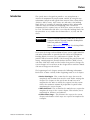
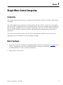
1
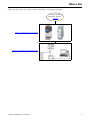
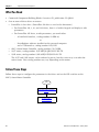
Simple Motor Control Connected
Components Building Block
Quick Start
Important User Information
Solid state equipment has operational characteristics differing from those of electromechanical equipment. Safety Guidelines
for the Application, Installation and Maintenance of Solid State Controls (publication SGI-1.1 available from your local
Rockwell Automation sales office or online at http://literature.rockwellautomation.com) describes some important differences
between solid state equipment and hard-wired electromechanical devices. Because of this difference, and also because of the
wide variety of uses for solid state equipment, all persons responsible for applying this equipment must satisfy themselves
that each intended application of this equipment is acceptable.
In no event will Rockwell Automation, Inc. be responsible or liable for indirect or consequential damages resulting from the
use or application of this equipment.
The examples and diagrams in this manual are included solely for illustrative purposes. Because of the many variables and
requirements associated with any particular installation, Rockwell Automation, Inc. cannot assume responsibility or liability
for actual use based on the examples and diagrams.
No patent liability is assumed by Rockwell Automation, Inc. with respect to use of information, circuits, equipment, or
software described in this manual.
Reproduction of the contents of this manual, in whole or in part, without written permission of Rockwell Automation, Inc., is
prohibited.
Throughout this manual, when necessary, we use notes to make you aware of safety considerations.
WARNING
IMPORTANT
Identifies information about practices or circumstances that can cause an explosion in a hazardous environment, which may
lead to personal injury or death, property damage, or economic loss.
Identifies information that is critical for successful application and understanding of the product.
ATTENTION
Identifies information about practices or circumstances that can lead to personal injury or death, property damage, or economic
loss. Attentions help you identify a hazard, avoid a hazard, and recognize the consequence.
SHOCK HAZARD
Labels may be on or inside the equipment, for example, a drive or motor, to alert people that dangerous voltage may be present.
BURN HAZARD
Labels may be on or inside the equipment, for example, a drive or motor, to alert people that surfaces may reach dangerous
temperatures.
Allen-Bradley, MicroLogix, PanelView, PanelView Component, PowerFlex, SMC, SMC-3, TechConnect, and Rockwell Automation are trademarks of Rockwell Automation, Inc.
Trademarks not belonging to Rockwell Automation are property of their respective companies.
Where to Start
Follow the path below for simple starting, controlling, and monitoring motors.
Connected Components
Building Blocks, publication
CC-QS001
Chapter 1 Simple Motor Control Integration
Chapter 2 System Validation and Application Tips
3Publication CC-QS006A-EN-P - January 2009
3
Where to Start
Notes:
4
Publication CC-QS006A-EN-P - January 2009
Table of Contents
Preface
Introduction . . . . . . . . . . . . . . . . . . . . . . . . . . . . . . . . . . . . 7
Conventions Used in This Manual . . . . . . . . . . . . . . . . . . . . 8
Additional Resources . . . . . . . . . . . . . . . . . . . . . . . . . . . . . . 9
Chapter 1
Simple Motor Control Integration
Introduction . . . . . . . . . . . . . .
Before You Begin . . . . . . . . . .
What You Need. . . . . . . . . . . .
Follow These Steps . . . . . . . . .
Set up the PowerFlex 4M Drive
Set up the SMC-3 Controller . . .
.
.
.
.
.
.
.
.
.
.
.
.
.
.
.
.
.
.
.
.
.
.
.
.
.
.
.
.
.
.
.
.
.
.
.
.
.
.
.
.
.
.
.
.
.
.
.
.
.
.
.
.
.
.
.
.
.
.
.
.
.
.
.
.
.
.
.
.
.
.
.
.
.
.
.
.
.
.
.
.
.
.
.
.
.
.
.
.
.
.
.
.
.
.
.
.
.
.
.
.
.
.
.
.
.
.
.
.
.
.
.
.
.
.
.
.
.
.
.
.
.
.
.
.
.
.
.
.
.
.
.
.
11
11
12
12
13
16
Chapter 2
System Validation and Application Introduction . . . . . . . . . . . . . . . . . . . . . . . . . . . . . . . . . . . . 19
Before You Begin . . . . . . . . . . . . . . . . . . . . . . . . . . . . . . . . 19
Tips
What You Need. . . . . . . . . . . . . . . . . . . . . . . . . .
Follow These Steps . . . . . . . . . . . . . . . . . . . . . . .
Connect PVc Terminal to Personal Computer . . . .
Configure PVc Terminal to MicroLogix Controller
Communication . . . . . . . . . . . . . . . . . . . . . . .
Navigating the Starters Overview Page . . . . . .
Test the Simple Starting Application Functionality .
Navigating the Simple Starting Screen . . . . . . .
Understanding Faults . . . . . . . . . . . . . . . . . . .
Test the SMC-3 Controller . . . . . . . . . . . . . . .
Testing Other Drives and Starters . . . . . . . . . .
Publication CC-QS006A-EN-P - January 2009
. . . . . . . . 20
. . . . . . . . 20
. . . . . . . . 21
.
.
.
.
.
.
.
.
.
.
.
.
.
.
.
.
.
.
.
.
.
.
.
.
.
.
.
.
.
.
.
.
.
.
.
.
.
.
.
.
.
.
.
.
.
.
.
.
.
.
.
.
.
.
.
.
22
24
25
25
28
29
30
5
Table of Contents
Notes:
6
Publication CC-QS006A-EN-P - January 2009
Preface
Introduction
This Quick Start is designed to provide a way to implement a
connected component for simple motor control. By using discrete
information (simple on-off signals from contacts) from a PowerFlex
4M drive, SMC-3 starter, 103T starter, or 190E starter, this building
block shows an example of extracting important basic information
about the status of a motor and displaying it on a PanelView
Component (PVc) terminal. Any or all of these starters or drives can
be used. The PowerFlex 4M drive is used for this building block, but
the procedure is very similar for the PowerFlex 4, 40, 40P, and 400
drives.
IMPORTANT
Use this Connected Components Building Block Quick Start in
conjunction with the Connected Components Building Blocks
Quick Start, publication CC-QS001.
Refer to Additional Resources on page 9 for a listing of Quick
Start documents.
To assist in the design and installation of your system, application files
and other information are provided on the Connected Component
Building Blocks Overview CD, publication CC-QR001. The CD
provides bills of materials (BOM), CAD drawings for panel layout and
wiring, control programs, Human Machine Interface (HMI) screens,
and more. With these tools and the built-in best-practices design, the
system designer is free to focus on the design of their machine control
and not on design overhead tasks.
The beginning of each chapter contains the following information.
Read these sections carefully before beginning work in each chapter:
• Before You Begin - This section lists the steps that must be
completed and decisions that must be made before starting that
chapter. The chapters in this quick start do not have to be
completed in the order in which they appear, but this section
defines the minimum amount of preparation required before
completing the current chapter.
• What You Need - This section lists the tools that are required to
complete the steps in the current chapter. This includes, but is
not limited to, hardware and software.
• Follow These Steps - This illustrates the steps in the current
chapter and identifies which steps are required to complete the
examples.
Publication CC-QS006A-EN-P - January 2009
7
Preface
Conventions Used in This
Manual
This manual uses the following conventions.
Convention
Meaning
Example
Click
Click the left mouse button once.
Click Edit.
Type
What you type on the keyboard.
Type the IP address.
Right-click
Click the right mouse button once while the cursor is positioned
on object or selection.
Right-click the 1768 Bus icon.
Select
Using the mouse to highlight a specific option.
Select the application name.
Press
Pressing a specific key on the keyboard or the PowerFlex 4M
keypad.
Press Enter.
Touch
Touching a specific button on the PanelView Component (PVc)
terminal.
Touch the Start button.
8
Publication CC-QS006A-EN-P - January 2009
Preface
Additional Resources
Resource
Description
Connected Components Building Blocks Quick Start, Provides information on how to select products and gain access to panel and wiring
publication CC-QS001
information.
Connected Component Building Blocks Overview
CD, publication CC-QR001
Provides files for the Connected Component Building Blocks.
Bulletin 150 SMC-3 (1-37A)/SMC-Delta (1-32A)
Soft Starter Connecting Modules 41053-173-01 (1)
Provides information on the connecting modules with the SMC-3.
Bulletin 150 SMC-3 Soft Starter (3-37A) 41053-167- Provides information on installation and settings of the SMC-3.
01 (5)
Bulletin 193 E1 Plus Overload Relay 41053-358-01
(3)
Provides information on the installation and settings of the overload.
Motor Protection Circuit Breakers / Motor Circuit
Protectors 21-301-951-01
Provides installation instructions for the MPCB and the MCP.
Position Control Connected Components Building
Block Quick Start, publication CC-QS003
Provides information on installing and setting up the PowerFlex 40P drive
parameters with the pre-configured RSLogix 500 program that controls your base
system including application tips, as well as implementing the drive parameter
backup and restore functionality.
MicroLogix 1100 Programmable Controllers User
Manual, publication 1763-UM001
Provides information on using the MicroLogix 1100 Programmable Controller.
MicroLogix 1400 User Manual, publication 1766UM001
Provides information on using the MicroLogix 1400 Programmable Controller.
PanelView Component Quick Start Manual,
publication 2711C-QS001A
Provides information on using the PanelView component.
PanelView Component Operator Terminals User
Manual, publication 2711C-UM001
Provides information on using the PanelView Component HMI Terminals.
PowerFlex 4M User Manual, publication 22FUM001
Provides information on installing the PowerFlex 4M Adjustable Frequency AC Drive
including wiring and parameter setup.
PowerFlex 4 User Manual, publication 22A-UM001
Provides information on installing the PowerFlex 4 Adjustable Frequency AC Drive
including wiring and parameter setup.
PowerFlex 40 User Manual, publication 22B-UM001 Provides information on installing the PowerFlex 40 Adjustable Frequency AC Drive
including wiring and parameter setup.
PowerFlex 40P User Manual, publication 22DUM001
Provides information on installing the PowerFlex 40P Adjustable Frequency AC Drive
including wiring and parameter setup.
PowerFlex 400 User Manual, publication 22CUM001
Provides information on installing the PowerFlex 400 Adjustable Frequency AC Drive
including wiring and parameter setup.
http://www.ab.com/drives/driveexplorer
Provides access to DriveExplorerLite software.
http://www.ab.com
Provides access to the Allen-Bradley website.
http://rockwellautomation.com/knowledgebase
Provides access to self-service support.
http://www.rockwellautomation.com/components/
connected
Provides access to the Connected Components website.
Publication CC-QS006A-EN-P - January 2009
9
Preface
Notes:
10
Publication CC-QS006A-EN-P - January 2009
Chapter
1
Simple Motor Control Integration
Introduction
This chapter provides instructions to configure the PowerFlex 4M drive and SMC-3 Smart Motor
Controller.
You will configure two parameters in the PowerFlex 4M drive. These are the basic parameters
that need to be changed from the factory default settings in order to establish proper feedback to
the MicroLogix controllers. For your machine application, there may be other drive parameters
that need to be adjusted. Consult your drive documentation for information on other drive
parameters.
You will also set the DIP switches on the SMC-3 Smart Motor Controller necessary to send
appropriate discrete feedback to the MicroLogix controller.
Before You Begin
•
Review the Connected Components Building Blocks Quick Start, publication CC-QS001, in its
entirety, verifying that you have completed hardware design and installation
recommendations as well as software installation.
•
Apply power to your drive.
Publication CC-QS006A-EN-P - January 2009
11
Chapter 1
Simple Motor Control Integration
What You Need
•
Connected Component Building Blocks Overview CD, publication CC-QR001.
•
One or more of these drives or starters:
– PowerFlex 4-class drive. (PowerFlex 4M drive is used in this document.)
• For PowerFlex 4M, 4, 40, and 400 drives, there is a built-in keypad and display to edit
parameters.
• For PowerFlex 40P drive, to edit parameters, you need either:
-
A hand-held interface, catalog number 22-HIM-A3
or
–
–
–
DriveExplorer software installed on the personal computer
and a USB interface, catalog number 1203-USB
SMC-3 Smart Motor Controller, catalog number 150-C3NBR.
103T starter, catalog number 103T-AWDJ4-QB25S-E1C-KN-TE.
190E starter, catalog number 190E-ANEJ2-CB25S-KN-S10-TE.
The 103T and 190E starters can be ordered in pieces, but the easiest way is to order the
entire starter. Your catalog number may vary depending on the motor.
Follow These Steps
Follow these steps to configure the parameters in the drives and set the DIP switches on the
SMC-3 Smart Motor Controller.
Start
Set up the PowerFlex 4M Drive,
page 13
Set up the SMC-3
Controller, page 16
12
Publication CC-QS006A-EN-P - January 2009
Simple Motor Control Integration
Chapter 1
Set up the PowerFlex 4M Drive
Factory-default parameter values allow the drive to be controlled from the integral keypad. No
programming is required to start, stop, change direction, and control speed directly from the
integral keypad.
However, for this building block, you will set parameter P106 [Start Source] for 2-wire control. In
the example for this building block, the PF 4M drive is used in a 2-wire SRC Control (internal
sourcing) Non-Reversing mode. SRC is the default for a new drive. If your drive has been used
previously, make sure the SNK/SRC (Sink/Source) switch under the front cover of the PF 4M
drive is set to SRC. See the PF 4M drive user manual for your specific needs other than shown in
this example.
In addition, you will change parameter t221 [Relay Out Sel] to display ‘MotorRunning’ since this
building block uses the ‘MotorRunning’ setting of parameter t221 to indicate the motor is
receiving power from the drive. See Testing Other Drives and Starters, page 30 for details.
Follow this procedure to change parameters P106 [Start Source] and t221 [Relay Out Sel] using the
PowerFlex 4M keypad explained below.
PowerFlex 4M Keypad
Key
Key Name
Escape
Select
Description
• Go back one step in Program mode.
• Cancel a change to a parameter value and exit Program mode.
• Advance one step in the programming menu.
• Select a digit when viewing a parameter value.
Up arrow
• Scroll through groups and parameters.
• Increase and decrease the value of a flashing digit.
Down arrow
Enter
Publication CC-QS006A-EN-P - January 2009
• Advance one step in the programming menu.
• Save a change to a parameter value.
13
Chapter 1
Simple Motor Control Integration
Stop the drive before changing parameter P106.
1. Press Esc until ‘0.0’ is displayed.
2. Press Sel until the leftmost character is flashing.
3. Press the Down arrow until the leftmost character displayed is a flashing 'P'.
4. Press Enter.
The 'P' stops flashing and the rightmost numeric key is flashing.
By default, the first 'P' parameter, P101, is displayed. Pressing the Up arrow increases and
pressing the Down arrow decreases the value of the 'P' parameters.
5. Press the Up arrow five times to display P106.
The current value of parameter P106 is displayed, ‘0’ in this case.
6. Press Enter.
The ‘0’ flashes.
7. Press the Up arrow twice to adjust the value to ‘2’.
8. Press Enter.
The value is accepted.
The ‘2’ should not be flashing any longer. Notice that the green status indicator next to the
green Start button is now off.
9. Press Esc.
P106 should be displayed with the ‘6’ flashing.
10. Press Esc until the 'P' is flashing on the leftmost alphanumeric character.
11. Press the Up arrow or Down arrow to scroll through the group menu to 't'.
12. Press Enter.
The ‘1’ flashes.
14
Publication CC-QS006A-EN-P - January 2009
Simple Motor Control Integration
Chapter 1
13. Press and hold down the up arrow until you reach ‘221’.
If you go past it, push the down arrow until you return to ‘221’.
14. Press Enter twice so that ‘0’ is flashing.
15. Press the up arrow to move to the value ‘2’.
16. Press Enter.
The value is accepted. The ‘2’ should not be flashing any longer. Notice that the green status
indicator next to the green Start button is now off.
17. Press Esc.
Parameter t221 should now be displayed with the ‘1’ flashing.
18. Press Esc until ‘0.0’ is displayed.
19. Power the drive off until the display goes blank and then power it back on.
Your drive is now configured to be controlled by push buttons and communication
commands initiated from the MicroLogix controller.
As with all building blocks, these are examples of getting information back discretely from a
product. You can change parameter t221 or other settings of the starters and drives to suit your
application.
Publication CC-QS006A-EN-P - January 2009
15
Chapter 1
Simple Motor Control Integration
Set up the SMC-3 Controller
The SMC-3 Smart Motor Controller needs to be set up for the isolation contactor and for the
appropriate settings for the motor. Below are the DIP switch settings used by the SMC-3
controller and the steps to change them.
TIP
16
The 140M MPCB specified in the BOM for this building block has a trip class of 10. However, if you
would like to use the overload trip class settings on the SMC-3 controller, you can change out the
140M MPCB with the 140M MCP.
Publication CC-QS006A-EN-P - January 2009
Simple Motor Control Integration
Chapter 1
1. Set the DIP switch settings to the starting needs of your motor using the chart below.
Publication CC-QS006A-EN-P - January 2009
17
Chapter 1
Simple Motor Control Integration
2. Be sure that DIP switch 14 is set to Normal (off).
This will bring in the isolation contactor when the SMC-3 has received the input signal. DIP
switch 14 will also close the side-mounted N.O. aux contact when the starter comes up to
speed. The closure of this aux contact will send the signal back to the MicroLogix controller.
3. If changing to an MCP, set DIP switches 11 and 12 to the appropriate overload trip class.
IMPORTANT
The 103T starter uses a 140M MCP (Motor Circuit Protector), which uses a separate overload, E1 Plus,
which must be set according to your system needs.
The 190E starter, the SMC-3 starter, and the PF 4M drive must have the overload dial set on the 140M
MPCB (Motor Protection Circuit Breakers).
Additional Resources
Refer to page 9 for a listing of product and information resources.
18
Publication CC-QS006A-EN-P - January 2009
Chapter
2
System Validation and Application Tips
Introduction
In this chapter, you validate that communication is occurring as intended between the MicroLogix
controller and the individual discrete starters, as well as between the MicroLogix controller and
the PanelView Component (PVc) terminal. Starting and stopping using the PVc terminal entails
having the external HOA switch in Auto position. In Hand mode, the PVc terminal can still read
status of the starters and drives, but will not have start/stop capabilities.
Before You Begin
•
Review the Connected Components Building Blocks Quick Start, publication CC-QS001, in its
entirety, verifying that you have completed all of the steps in Chapter 3 of that document.
•
Verify that you have completed all of the steps in Chapter 1 of this document.
•
Verify that all the devices are connected per the Simple Motor Control CAD wiring diagram on
the Connected Component Building Blocks Overview CD, publication CC-QR001.
•
Verify that the MicroLogix controller, PowerFlex drive, and PVc terminal have power applied
to them.
19Publication CC-QS006A-EN-P - January 2009
19
Chapter 2
System Validation and Application Tips
What You Need
•
Connected Component Building Blocks Overview CD, publication CC-QR001.
•
Personal computer with either Internet Explorer 7 or Firefox web browser.
•
PanelView Component terminal.
•
One or more of these drives or starters:
•
PowerFlex 4M drive.
•
SMC-3 Smart Motor Controller, catalog number 150-C3NBR.
•
103T starter, catalog number 103T-AWDJ4-QB25S-E1C-KN-TE.
•
190E starter, catalog number 190E-ANEJ2-CB25S-KN-S10-TE.
The 103T and 190E starters can be ordered in pieces, but the easiest way is to order the
entire starter. Your catalog number may vary depending on the motor.
•
MicroLogix 1100 or 1400 controller.
•
Serial cable, catalog number 1761-CBL-PM02.
•
USB cable, catalog number 2711C-CBL-UU02 or comparable.
Follow These Steps
Follow these steps to verify that communication is occurring between your devices and to test the
system.
Start
Connect PVc Terminal to
Personal Computer, page 21
Configure PVc Terminal to
MicroLogix Controller
Communication, page 22
Test the Simple Starting
Application Functionality, page 25
20
Publication CC-QS006A-EN-P - January 2009
System Validation and Application Tips
Chapter 2
Connect PVc Terminal to Personal Computer
The PanelView Explorer design-time environment is accessed through a web browser by
connecting your computer to the PVc terminal with a USB connection. Before connecting your
computer to the USB port of the PVc terminal, you must first install the PanelView USB RNDIS
Device driver on a computer with Windows XP or Vista operating system. After installing the
driver, you can connect the PVc terminal to your computer. For details on how to install the
driver, refer to the PanelView Component Terminal User Manual, publication 2711C-UM001
PVc Terminal USB Connections
PanelView Explorer
Startup Window
USB port
USB port
USB cable, 2711C-CBL-UU02
All PanelView Component terminals support a USB port connection and require a computer with
Windows XP or Vista operating system, and with the PanelView USB RNDIS Device driver
installed. The driver cannot be installed on a computer with Windows 2000 operating system.
1. Connect one end of a USB cable to the miniUSB device port on your PVc terminal.
2. Connect the other end of the USB cable to a
USB port on your personal computer.
3. Power up the PVc terminal and the personal
computer.
Publication CC-QS006A-EN-P - January 2009
USB port
USB port
USB cable, 2711C-CBL-UU02
21
Chapter 2
System Validation and Application Tips
Configure PVc Terminal to MicroLogix Controller Communication
The 3-inch monochrome touch screen PanelView Component (PVc) terminal communicates with
the MicroLogix controller over the DF1 network. The PVc application reads from and writes to
the data table of the MicroLogix controller. When the PVc application writes to the MicroLogix
controller, the controller program detects the value change and writes that new value to the
appropriate drive, soft starter, or discrete starter.
1. Connect the personal computer to the PVc terminal using a USB cable.
USB port
USB port
USB cable, 2711C-CBL-UU02
1761-CBL-PM02
MicroLogix controller
2. Connect the PVc terminal to MicroLogix controller using the 1761-CBL-PM02 serial cable.
3. Start either Internet Explorer 7 or Firefox 2.0.
4. In the address bar of your browser, type the IP address 169.254.254.2. (This is a fixed IP
address that the USB port uses.)
5. Press Enter to connect your personal computer to the PVc terminal.
22
Publication CC-QS006A-EN-P - January 2009
System Validation and Application Tips
Chapter 2
6. Select the application name in the PVc dashboard dialog box and then click Edit.
7. In the Edit dialog box, click the Communication tab.
The following dialog box appears.
Validate button
8. Click Serial under Protocol and select DF1 from the pull-down list.
9. Under PanelView Component Settings, verify the Station Address is 2.
Publication CC-QS006A-EN-P - January 2009
23
Chapter 2
System Validation and Application Tips
10. Under Controller Settings:
a. Accept the default name ‘PLC-1’.
b. Select MicroLogix from the Controller Type field.
c. In the Address field, type 1.
11. Click Validate.
12. Click Save.
13. Click Switch to PanelView Explorer Startup.
14. In the Application Dashboard window, select the Simple Starting Building Block application.
15. Click Run to run the application.
Navigating the Starters Overview Page
When the PVc application is running, any drive or starter that is enabled is shown on the Starters
Overview screen as being ‘140M On’, ‘Running’ or ‘Fault’. To ease the use of this program by the
OEM, the header for the starter is left generic for the ability to change starters without the need to
change the PVc first page. To change the buttons themselves, please see the PanelView
Component HMI Terminals user manual.
•
‘M1’ is designated for the SMC-3 controller.
•
‘M2’ is designated for the 103T starter.
•
‘M3’ is designated for the PF 4M drive.
•
‘M4’ is designated for the 190E starter.
24
Publication CC-QS006A-EN-P - January 2009
System Validation and Application Tips
Chapter 2
•
Stopped indicates the starter is stopped.
•
140M On indicates that the 140M overload is in the ‘On’ position for the specific drive or
starter.
•
Starting (not shown) indicates the starter or drive is starting.
•
Running indicates that motor is running based on feedback from the starter or drive.
•
Fault indicates that there is an overload, short circuit, or other fault the starter has detected.
Touching anywhere on Stopped, 140M On, Running, Fault or M# takes you to the individual
starter screens regardless of the status shown..
TIP
At this point, you may choose to edit the Starters Overview screen and delete any buttons and
status displays that are associated with non-existing starters or drives.
Test the Simple Starting Application Functionality
Now that the PVc terminal is successfully communicating with the MicroLogix controller, you are
ready to test the Simple Starting functionality.
Navigating the Simple Starting Screen
Touch any of the MTR# or M# buttons on the Starters Overview screen to get to each individual
starter screen such as these for the SMC-3 and VFD starter screens.
Publication CC-QS006A-EN-P - January 2009
25
Chapter 2
System Validation and Application Tips
The
in the top-right corner exits the application and goes to the PVc Terminal Starters
Overview screen.
The 190E and 103T screens are similar to that for the SMC-3 controller, with the exception of the
fault button on the starter screen.
The SMC-3 screen shows the following states.
The right column of the starter screen indicates the following:
•
Start is a momentary start button which appears when the starter/drive is in Auto and the
140M is Ready. Touching this button starts the starter or drive.
•
Stop is also a momentary button. Touching this button stops the starter/drive.
If the HOA (Hand Off Auto), is not in Auto, the Start and Stop buttons will not appear, nor
will they appear without a 3 Ph On signal. In this building block, a signal of ‘1’ back to the
PLC indicates an Auto position, a signal of ‘0’ back indicates a hand or off position. You can
add an additional contact block to the HOA for the hand position and feedback to the PLC to
give that status also.
The center column of the SMC-3 starter screen indicates the following:
•
3 Ph On indicates that the 140M overload is in the ‘On’ position for the specific drive or
starter.
•
3 Ph Off indicates that the 140M overload is in the ‘Off’ position.
•
Stopped indicates the SMC-3 controller is stopped.
•
Starting indicates the motor is starting.
•
At Speed indicates the motor is running and is at speed.
•
Start Fail indicates the starter or drive received a start signal but did not start within the time
set in the RSLogix program.
Causes/Remedies When getting a Start Fail indication, check the starter, drive, and/or motor
for wiring issues or damage. In addition, the Start Fail indication may occur due to too short a
time for the Timer On Delay in the ladder program in the Micrologix controller. See Timer On
Delay below.
Reset procedure To reset the Start Fail on the PVc terminal when using the SMC-3 controller or
the 103T or 190E starters, turn the front knob on the 140M MPCB or MCP to off, and then
back to on to clear the indication. To clear this indication on the drive, press the stop button
on the either on the PVc terminal in Auto mode, or press the stop button in Hand mode.
26
Publication CC-QS006A-EN-P - January 2009
System Validation and Application Tips
Chapter 2
Timer On Delay The timer is started when the Start signal is sent to the starter or drive. At the
end of the timing, a comparison is done to see if the motor has actually started. The time
duration for the Timer On Delay is fully adjustable in the ladder program in the Micrologix
controller. For this building block, the timers are set to 35 seconds for the SMC-3 controller
and the PF 4M drive and 5 seconds for the 103T and 190E starters. Check rung 3 or 4 of the
default program for the timer.
The left column of the starter screen indicates the following:
•
Fault indicates that the starter has detected a fault.
Not all starters have this capability.
The SMC-3 controller and the PF 4M drive can provide this information. When the fault
indication appears on the SMC-3 controller, touching Fault takes you to the listed fault screen
for the controller.
The PF 4M drive VFD screen always has the Fault button displayed. If a fault appears on the
PF 4M drive, the fault code is displayed on the drive. You can press the Fault button on the
PVc terminal to view the fault description. You can scroll through the fault list, just as with the
SMC-3 controller.
The fault indication on the 103T or 190E starter screen does not have this fault screen
functionality since these starters do not provide additional information.
•
OVLD indicates that there is an overload detected by the starter.
•
S.C. indicates that there is a short circuit detected by the starter.
Publication CC-QS006A-EN-P - January 2009
27
Chapter 2
System Validation and Application Tips
Understanding Faults
The Fault button is always present on the ‘VFD’ screen on the PVc terminal. This Fault button on
the ‘VFD’ screen is merely a GoTo button and does not, by itself, indicate a fault condition with
the PF 4M drive. The SMC-3 controller, however, sends a signal back to the PVc terminal
indicating a fault with the controller. The Fault GOTO button is then displayed on the ‘SMC-3’
screen on the PVc terminal. Pressing the Fault button on the ‘VFD’ Fault screen or on the ‘SMC-3’
Fault screen takes you to the individual fault screens where you can scroll through to find the
fault indicated on the PF 4M drive or the SMC-3 controller, and its corresponding description.
’VFD’ Fault Screen (for PF 4M Drive)
‘SMC-3’ Fault Screen
In both cases, look at the fault code on the PF 4M drive or SMC-3 controller.
•
For the PF 4M drive, you must view the fault code on the drive. Press the Fault button on the
‘VFD’ screen on the PVc terminal to view the fault listing. Locate the specific fault for the
drive. To get a deeper description of the fault, consult the user manual for the drive.
•
The SMC-3 Controller will have a flashing LED and you need to count the number of flashes.
Then on the PVc terminal, scroll through the fault listing screen and identify the fault, using
the number of flashes for identification.
The
button in the lower-right corner of the fault listings takes you back to the SMC-3 or
VFD starter screen.
28
Publication CC-QS006A-EN-P - January 2009
System Validation and Application Tips
Chapter 2
Test the SMC-3 Controller
Follow this procedure to test the SMC-3 controller.
1. Make sure the motor is disconnected from the load, for ease of testing in this procedure.
2. Verify that the external HOA is in Auto mode.
3. Verify that the 140M is in the ON position (I).
This enables the 3-phase power to the starter.
4. Verify that there is no Fault, OVLD, or S.C. state. If there
is, check the PVc terminal for the error condition. The
screen should look like this.
5. Verify that the 3 Ph On indicator is present.
6. Verify that the Start and Stop buttons are present.
7. Make sure that the SMC-3 controller has the proper DIP switch setting for your application
(for example, ramp time, current limit, or soft start).
8. Touch the Start button.
9. Verify the following:
•
The isolation contactor pulls in.
•
The motor starts according to the starting method selected for the SMC-3 controller.
•
The Running indication appears when the motor is up to speed.
10. Touch the Stop button to stop the motor.
11. Unplug the 1761-CBL-PM02 serial cable from the PVc terminal going to the MicroLogix
controller.
Publication CC-QS006A-EN-P - January 2009
29
Chapter 2
System Validation and Application Tips
12. Verify these error messages appear on the PVc terminal. There will be multiple errors referring
to:
•
Remote Device PLC-1 Is Not Responding
•
Data Access Error for Allas Starter_4_status_word, Controller PLC-1
•
Data Access Error for Allas Starter_3_status_word, Controller PLC-1
•
Data Access Error for Allas Starter_2_status_word, Controller PLC-1
•
Data Access Error for Allas Starter_1_status_word, Controller PLC-1
13. Press OK on all the pop-up screens.
14. Reinstall the serial cable.
15. Verify that all screens appear normal.
If there is an error on the displays, check the connection from the PVc terminal to the
MicroLogix controller.
Testing Other Drives and Starters
You can use the Test the SMC-3 Controller procedure for the PF 4M drive and the 190E and 103T
starters, since the screens on the PVc terminal are similar to the SMC-3 controller with the
exception of the Fault button on the ‘VFD’ screen. The Fault button on the ‘VFD’ screen is always
present. The reason is that the PF 4M drive has only one form C-type relay out. Therefore, the
information that can be signaled from the relay is selectable by setting parameter t221. This
building block uses the ‘MotorRunning’ setting of parameter t221 [Relay Out Select] to indicate the
motor is receiving power from the drive.
Additional Resources
Refer to page 9 for a listing of product and information resources.
30
Publication CC-QS006A-EN-P - January 2009
Rockwell Automation
Support
Rockwell Automation provides technical information on the Web to assist
you in using its products. At http://support.rockwellautomation.com, you can
find technical manuals, a knowledge base of FAQs, technical and application
notes, sample code and links to software service packs, and a MySupport
feature that you can customize to make the best use of these tools.
For an additional level of technical phone support for installation,
configuration, and troubleshooting, we offer TechConnect Support programs.
For more information, contact your local distributor or Rockwell Automation
representative, or visit http://support.rockwellautomation.com.
Installation Assistance
If you experience a problem with a hardware module within the first 24
hours of installation, please review the information that's contained in this
manual. You can also contact a special Customer Support number for initial
help in getting your module up and running.
United States
1.440.646.3434
Monday – Friday, 8 a.m. – 5 p.m. EST
Outside United
States
Please contact your local Rockwell Automation representative for any
technical support issues.
New Product Satisfaction Return
Rockwell tests all of its products to ensure that they are fully operational
when shipped from the manufacturing facility. However, if your product is
not functioning, it may need to be returned.
United States
Contact your distributor. You must provide a Customer Support case
number (see phone number above to obtain one) to your distributor in
order to complete the return process.
Outside United
States
Please contact your local Rockwell Automation representative for
return procedure.
Publication CC-QS006A-EN-P - January 2009
Copyright © 2009 Rockwell Automation, Inc. All rights reserved. Printed in the U.S.A.