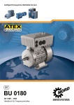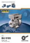
1
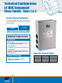
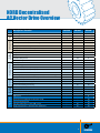
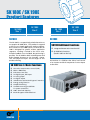
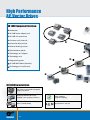
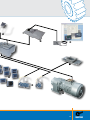
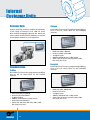
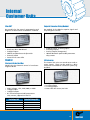
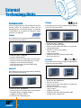
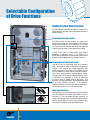
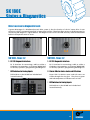
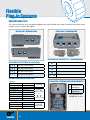
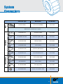
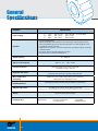
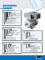
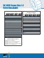
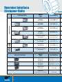
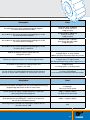
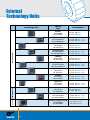
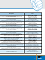
Intelligent Drivesystems SK 180E High Performance AC Vector Drives Innovative Decentralized Drive Technology F3018 Table of Contents Product Series Page SK 180E product series 3 SK 180E Family Overview 4 Flexible Solutions SK 180E Features 6 AS Interface Connection 7 Application Functions 8 NORDCON 9 Flexible Mounting Positions 10 Assembly Diagram 12 Options Internal Customer Units 14 External Technology Units 17 Control Units 21 Drive Function Configuration 22 Status & Diagnostics 23 Flexible Plug-in Systems 24 System Connectors 25 Ordering Information General Specifications 26 Selection Guides 28 Ratings 30 Customer / Technology Unit Overview 32 Braking Resistors 36 Dimensions 38 2 Compact & Decentralized AC Vector Drives AC Vector Drive Series SK 180E NORD, the drive technology specialist, has been developing and producing distributed control AC vector drives for more than 10 years. In 2009, we introduced the very popular SK 200E AC vector drive series, which was designed to mount directly in place of the motor terminal box to create a combined, fully integrated unit for use in the field. The SK 200E line is a distributed control companion to our successful SK 500E series cabinet mount drive. Together, our products offer a continuous range of performance along with optional features to simplify the drive selection process in order to serve a wide variety of applications. Although the original SK 200E series served the full range of drive applications from simple speed control in stand alone units to complex multi drive systems controlled via field bus networks or requiring position control, our customers have encouraged us to expand our product offering even further. NORD now offers a new product that fills the gaps between simple motor starters and complex AC drives. Many applications do not utilize the immense scope of functionality found in modern frequency inverters. This is why NORD has developed the SK 180E. This product focuses on the essential functionality that is necessary for pumps and conveyor technology. The SK180E is extremely energy efficient, cost effective and offers both significant savings as well as outstanding performance. 3 Technical Configuration of 180E Component Class Family - Sizes 1 & 2 SK 180E: Technical Configuration The drives included in this family are best suited for stand alone drives as well as mixers, extruders, pumps and fans. SK 180E SK 190E 0.33 - 3.0 hp (0.25 - 2.2 kW) SK180E Size 1-2 Basic Functions Control Signals 3 Digital Inputs E.G. For left/right release, fixed frequencies or the switching over of parameters. 2 Digital Outputs E.G. Reporting of errors or various limit values. 2 Analog Inputs Connection for voltage setpoint and may be configured for additional digital inputs for the use of sensors, etc. Integrated 24V Power Supply Internal Control Voltage Added without additional connection. "Stand Alone" operation. 4 Input Power/Frame Size Matrix Voltage HP Rating 0.33-0.75 115V ~ 1 0.33-1.5 240V ~ 1 0.33-1.5 240V ~ 3 0.25-3.0 480V ~ 3 Size details on page page 30. Frame Size 1 1&2 1&2 1&2 NORD Decentralised AC Vector Drive Overview SK 180E Description / Function Brake functions Configuration Type Power range Housing / Version Protection SK180E SK200E up to 10 hp up to 3 hp up to 30 hp Reversing, soft start - - - Connection for PTC temperature sensor Uniform parameter structure / error messages Configuration via software parameterisation Configuration via DIP switches and potentiometers Number of I/Os DIN / DOUT / AIN - 2/2/0 3/2/2 4 / 2(1) / 2 Integrated electronic brake rectifier - Integrated brake chopper - m** Internal braking resistor - m** m External braking resistor - m** m SK 100E SK 100E SK 200E Wall-mounting possible Protection class (climate class) IP55 (3k3) Protection class (climate class) IP66 (3k4) m m m ATEX Zone 22-3D m m m EMC rating: Radio interference suppression level (for motor mounting) C1 C1 C2 Leakage current (with active mains filter) Data / Bus interface SK135E Frequency inverter Housing version Functionality SK 190E < 20 mA < 16 mA > 30 mA PTC / I2t / Motor phase monitoring Overvoltage trip / Undervoltage protection Short-circuit / Earthing monitoring - RS 232 PC diagnostic interface Data storage via plug-in EEPROM - - System bus - m m m Interface for bus coupling STO function - - m Connection for incremental encoder (servo mode) - - Posicon positioning mode - - Sensorless current vector control (ISD control) - Energy saving function: "Automatic flux optimisation" - Standard Functions m Optional Functions ** Unavailable from 0 - 1.1 kW 5 SK 180E / SK 190E Product Features SK 180E Size 1 0.33 - 1.5 hp (0.25 - 1.1 kW) SK 180E Size 2 1.0 - 3.0 hp (0.75 - 2.2 kW) SK 180E SK 190E Size 2 SK 190E Size 1 0.33 - 1.5 hp (0.25 - 1.1 kW) 1.0 - 3.0 hp (0.75 - 2.2 kW) SK 190E The SK 180E is a competitively priced alternative to our popular SK 200E drive. This product is targeted at the low cost simple application market segment. Basic features of the 200E remain, however the SK 180E is designed for specific market application segments. Braking is limited to the size 2 units. Encoder feedback is not included. No positioning is possible. The SK 180E has built-in 24VDC power and brake chopper however on size 2 models. Pumps, fans and simple conveyors are the target for this product offering. SK 180E Size 1-2 Basic Functions: Sensorless current vector control (ISD) Mains / EMC Filter PI Process Controller 3x digital input, PTC input 2x analog input 2x digital output Immediate-access RS 232 diagnostic interface Energy saving function Simple field wiring Variable mounting possibilities for system connectors 200% Overload Capacity Brake Chopper + Brake Resistor* 6 SK 190E Additional Functions: Integrated Automation Interface ASi SK 180E basic functions (listed in table to the left) AS interface is a field bus that allows local control of an actuator and local acceptance of sensor inputs at the drive. AS Interface Connection with M12 Plug Connectors Modern automation systems have a wide range of requirements, so that a suitable bus system and drive components must be selected in order to ensure efficient implementation. For simple local control, the AS interface is a cost-effective solution which enables the networking of binary sensors and actuators. The SK 190E, provides an appropriate solution by means of an AS interface, and is available in this price-sensitive offering. The supply voltage (power) is via appropriate terminals according to the rating (1~/3~, 115/230/460V). For the control unit of the AC Vector Drive and the AS interface, the supply is via the (yellow) AS interface cable. This eliminates the need for an additional AUX cable (black). To connect the AS-i cable and any initiators, appropriate M12 plug connectors can be provided ex-works. These are color-coded in order to provide a definite assignment of functionalities in the field. The following versions can be selected as options. AS interface connection • AS interface Power (115V/230V/400V) • Optional M12- plug connector (yellow) for AS-i: SK TIE4-M12-AS1 (Part No. 275274502) AS interface Versions with AS-i on board: AS interface on board SK 190E basic functions Connection for AS interface and initiators SK 190E Size 1 0.33 - 1.5 hp (0.25 - 1.1 kW) SK 190E Size 2 1.0 - 3.0 hp (0.75 - 2.2 kW) • AS interface •Initiators (max. 4 x M12 connections possible, 2 with each digital input that is provided [2]) • Optional M12- plug connector (yellow) for AS-i: SK TIE4-M12-AS1 (Part No. 275274502) • Optional M12 plug connector (black) for I/O: SK TIE4-M12-INI (Part No. 275274503) 7 SK 180E Application Functions Application functions of the SK 180E Energy-saving function • Automatic flux optimisation for pump/fan applications Energy saving Energieeinsparung • Large energy savings possible • Simple setting via inverter parameters Einsatzenergy-efficient von energieeffizientenproducts NORD-Produkten With from NORD Mains EMC - Filter Class C1 (B) EMC Filtering • All 230/400V devices have an integrated mains filter • Also ideal for applications in a domestic environment, due to compliance with Class C1 (for motor mounting), or Class C2 (for wall mounting with motor cables up to 5 meters long) Rectifier • Suitable for personal protection due to low leakage current (<16mA) for operation with universal current FI circuit breakers PI process controller • All SK 180E devices feature 2 integrated analog inputs • P and I component may be set seperately • High precision regulation of application variables 8 NORD CON NORD CON NORD CON is the free operating software for controlling, programming and diagnosis of all NORD AC vector drives. SK180E Interface Connection Connecting a SK180E to a PC/laptop is the most effective way to control your AC Vector drive. Connection is accomplished via the RS232 diagnostic interface on top of the AC Drive. The cable does not come standard with the unit but is available. We can provide a 10 foot sub D to RJ12 connector cable but needs to be ordered seperately. (Part Number 278 910 240) Control The AC vector drive can be manually operated by means of a software window with all of the operating elements of a Controlbox. An enable signal with specification of setpoint values can be given. The parameter settings can be adjusted and read. Parameters (information and error messages) can be viewed. Users therefore have a supporting aid for each commissioning. Programming With a convenient overview, users can view and adjust each available parameter. By means of a print option complete parameter lists or lists of the changed values can be created. The finished data sets can be saved on the PC/laptop and archived for future use. Diagnosis The NORD CON oscilloscope function is a simple but very useful instrument for the optimal adjustment of drive systems. By means of line graphs, all drive characteristics (current, torque, etc.) can be recorded and analysed. With these results, application-relevant settings can be fine-tuned to enable optimum operation. This is useful, e.g. for regulating the brake control or for lifting gear functions. 9 Flexible Mounting Possibilities AC Vector Drive as a Motor or Wall Mount Option Motor Assembly Wall-Mounting (with or without fan) Technology Box on the SK 180E /190E or Wall Mounted Connected Via System Bus Cable OR 10 Motor-integrated SK 180E With Technology Unit Motor-integrated SK 180E With Wall Mounted Technology Unit Connected Via System Bus Cable Wall Mounted Variant of an SK 180E and a Technology Unit Motor Supply Cable (Terminal Box to 3L] Connected Via System Bus Cable (3R to 5L or 5R] 11 High Performance AC Vector Drives SK 180E Component Overview: Gearmotor SK 180E motor adapter unit SK 180E AC vector drive Customer unit (internal) Internal braking resistor External braking resistor Potentiometer option Technology unit adapter Technology units + Programming tools SK 180E Wall-Mount (bracket) Technology unit wall-mount SK 180E Characteristics: Units can be operated with all standard asynchronous motors Generously dimensioned for easy assembly of various system connectors RoHS compliance "Lead free soldering" Motor or wall mounting UL Certification / cUL / CE 12 13 Internal Customer Units Customer Units CANopen Internal customer interfaces enable the expansion of the range of functions of SK 180E AC vector drive without changing the physical size. Users have access to both communication modules, an internal control power module or an I/O expansion. Bus module for the control, programming and diagnosis of the AC vector drive via the CANopen interface. • • • • • Communication Profibus Baud rate: Max.1 MBaud Protocol: DS301 and DS402 2x digital inputs Address and baud rate via dip-switch Status LED: BG status, BG fault, DIN1, DIN2, Bus status, bus fault DeviceNet Bus module for the control, programming and diagnosis of the AC vector drive via the DeviceNet interface. Bus module for the control, programming and diagnosis of the AC vector drive via the Profibus interface. • • • • • • Baud rate: Max. 12 MBaud Protocol: DPV 0 and DPV 1 2x digital inputs Address and baud rate via dip-switch Automatic PPO detection Status LED: BG status, BG fault, DIN1, DIN2, Bus status, Bus fault 14 • • • • • Baud rate: Max. 500 kBaud Protocol: AC-Drive 2x digital inputs Address and baud rate via dip-switch Status LED: BG status, BG fault, DIN1, DIN2, Bus status, Bus fault Internal Customer Units EtherCAT® Setpoint Converter (Relay Module) Bus module for the control, programming and diagnosis of the AC drive via EtherCAT® interface. Bus module for the bipolar setpoint signals and relay changeover contacts. • • • • • Baud rate: Max. 100 MBaud 2x digital inputs Address and baud rate via dip-switch Protocol: DS301 Status LED: 6 status LEDs Control 2x digital inputs, 2x analog inputs 2x analog outputs 2x relay outputs (changeover) 100 mA Maximum permissable permanent relay current I/O Extension Electronic Brake Rectifier Module for the electronic control of an electromagnetic brake. • • • • • • • • Mains Voltage: 115V, 240V, 400V, or 480V. 1x digital input 1x digital output 0.5 A maximum permissable permanent relay current, suppression level C2 Line Voltage (AC) Brake Coil Voltage (DC) 100-120 105 200-240 105 380-420 180 440-480 205 The internal I/O units can record sensor and actuator signals. These can be used for a drive function or forwarded to a host bus system (e.g. Profibus). • • • • 2x digital inputs 2x analog inputs 1x analog output Status LEDs: Bus status, Bus fault 15 Internal Customer Units Operation Potentiometer Adapter With the Potentiometer Adapter a robust unit with switching (right-off-left) and a potentiometer may be integrated. This only changes the physical size by the size of the control elements. Connection is achieved with the use of an internal 24V control power module. Internal Customer Units Ordering Info Profibus Interface SK CU4-PBR (Part. No. 275 271 000 (Part. No. 275 271 500 IP55) IP66) CANopen Interface SK CU4-CAO (Part. No. 275 271 001 (Part. No. 275 271 501 IP55) IP66) DeviceNET Interface SK CU4-DEV (Part. No. 275 710 002 (Part. No. 275 710 502 IP55) IP66) EtherCAT Interface SK CU4-ECT • SK CU4-POT : Part Number - 275 271 207 • Additional option with analog input required for SK1X0E. Robust Switches for Potentiometers This is an upgrade to the standard Potentiometer box. There are more durable dials that are utilized and are available for both digital and analog input. (Part. No. 275 271 017 (Part. No. 275 271 517 IP55) IP66) Setpoint Converter (Relay Module) SK CU4-REL (Part. No. 275 271 011 (Part. No. 275 271 511 IP55) IP66) Electronic Brake Rectifier SK CU4-MBR (Part. No. 275 271 010 (Part. No. 275 271 510 IP55) IP66) I/O Extension SK CU4-IOE (Part. No. 275 271 006 (Part. No. 275 271 506 IP55) IP66) Potentiometer Adapter SK CU4-POT • SK TIE4-SWT : Part Number - 275 274 701 • Connection to digital inputs. • SK TIE4-POT : Part Number - 275 274 700 16 (Part. No. 275 271 207 (Part. No. 275 271 707 IP55) IP66) Robust Switches / Potentiometer SK TIE4-SWT (Part. No. 275 274 701) Connection to digital inputs SK TIE4-POT (Part. No. 275 274 700) External Customer Units Variable Mounting For the distributed control SK 180E AC vector drives, optional technology units are available. These units may be mounted directly on the device or separately on the machine frame or plant component. Communication systems both with & without connection facilities for sensors, actuators and control modules are available for most current applications. Tunneling of Parameter Data Via the System BUS The bus Technology units of the SK 180E provide economical and user-friendly configuration of the drive systems in the field. With the system bus, up to 4 AC vector drives and the bus technology unit can be linked via the system bus, which is integrated as standard. Therefore the connection to the host bus system is made at a single point. However, all data sets can be accessed by tunneling of the parameter data. Both the technology units and the data sets of each of the connected SK 180E devices can be accessed via the RS 232 interface. Field bus (e.g. Profibus) Technology unit mounted directly on the AC Vector Drive System bus Technology units for wall mounting 17 External Technology Units Communication CANopen External technology units are available for communication within an automation system and for recording sensor and actuator signals. Connection is either direct to a terminal or with M12 system connectors as required. Bus module for the control, programming and diagnosis of the AC vector drive. Profibus Bus module for the control, programming and diagnosis of the AC vector drive. • • • • • • Baud rate: Max. 12 MBaud Protocol: DPV 0 & DPV 1 Access of up to 4 AC vector drives via system bus Provision of I/Os on the Profibus: 4x In / 2x Out Diagnosis via RS 232 (RJ12 Interface) Status LED: BG status, BG fault, DIN1, DIN2, Bus status, Bus fault • • • • • • • Baud rate: Max. 1 MBaud Protocol: DS 301 and DS 402 Access of up to 4 AC vector drives via system bus Electrically isolated Provision of I/Os on the CANbus: -4x In / 2x Out Diagnosis via RS 232 Status LED: B6 status, B6 fault, DIN1, DIN2, Bus status, Bus fault DeviceNet DeviceNet Bus module for the control, programming and diagnosis of the AC vector drive. Ethernet IP Bus module for the control, programming and diagnosis of the AC vector drive. • • • • • Baud rate: Max. 100 MBaud Access of up to 4 AC vector drives via system bus 8x Digital inputs / 2x Digital outputs Diagnosis via UDP or TCP/IP Status LEDs for operating status 18 • • • • • • • Baud rate: Max. 500 kBaud Protocol: AC-Drive Access of up to 4 AC vector drives via system bus Electrically Isolated Provision of I/Os on the CANbus: -4x In / 2x Out Diagnosis via RS 232 Status LED: B6 status, B6 fault, DIN1, DIN2, module status, module fault EtherCAT An Ethernet based bus module for the control, programming and diagnosis of the AC vector drive. • • • • • • Baud rate: Max. 100 MBaud Protocol: CoE Access of up to 8 AC vector drives via system bus Provision of I/Os on the Profibus: 8x In / 2x Out Diagnosis via RS 232 Status LED: BG status, BG fault, DIN1, DIN2, Bus status, Bus fault Control I/O Extension With an external I/O Extension actuator signals may be included in distributed drive structures. These are transferred to the AC vector drive via the system bus and may be used as a drive function or forwarded to a host bus system (e.g. Profibus). One type of external I/O expansion provides a direct connection of four digital inputs (sensors) and two digital outputs (actuators). Because the design does not use connectors, the module is suitable for harsh environments. With the M12 I/O extension, there are M12 plug connectors in the front of the module that allow for quick replacement of connected sensors and actuators. ProfiNET An Ethernet ProfINET based bus module for the control, programming and diagnosis of the AC vector drive. Equipped with a RJ45 based connector that conforms to AIDA specification. • • • • • • Connection via system bus 4x digital inputs 2x digital outputs 2x analog inputs 1x analog output Status LEDs Maintenance Switch • • • • • • Baud rate: Max. 100 MBaud Protocol: ProfiNET IO Conformance class B Access of up to 8 AC vector drives via system bus Provision of I/Os on the Profibus: 8x In / 2x Out Diagnosis via RS 232 Status LED: BG status, BG fault, DIN1, DIN2, Bus status, Bus fault With this unit, you may switch off the supply of power or motor voltage to a drive and secure that drive against switching back on. This is very important when you are servicing or repairing a drive. 19 External Technology Units External Customer Units Ordering Information Profibus Interface and Adapter + + IP55 unit: SK TU4-PBR (Part. No. 275 281 100) SK TI4-TU-BUS (Part. No. 275 280 000) IP55 unit with M12 Connector: SK TU4-PBR-M12 (Part. No. 275 281 200) SK TI4-TU-BUS (Part. No. 275 280 000) + + IP55 unit: SK TU4-CAO (Part. No. 275 281 101) SK TI4-TU-BUS (Part. No. 275 280 000) IP55 unit with M12 Connector: SK TU4-CAO-M12 (Part. No. 275 281 201) SK TI4-TU-BUS (Part. No. 275 280 000) + + IP55 unit: SK TU4-DEV (Part. No. 275 281 102) SK TI4-TU-BUS (Part. No. 275 280 000) IP55 unit with M12 Connector: SK TU4-DEV-M12 (Part. No. 275 281 202) SK TI4-TU-BUS (Part. No. 275 280 000) + + IP66 unit: SK TU4-PBR-C (Part. No. 275 281 150) SK TI4-TU-BUS-C (Part. No. 275 280 500) IP66 unit with M12 Connector: SK TU4-PBR-M12-C (Part. No. 275 281 250) SK TI4-TU-BUS-C (Part. No. 275 280 500) CANopen Interface and Adapter + + IP66 unit: SK TU4-CAO-C (Part. No. 275 281 151) SK TI4-TU-BUS-C (Part. No. 275 280 500) IP66 unit with M12 Connector: SK TU4-CAO-M12-C (Part. No. 275 281 251) SK TI4-TU-BUS-C (Part. No. 275 280 500) DeviceNet Interface and Adapter + + IP66 unit: SK TU4-DEV-C (Part. No. 275 281 152) SK TI4-TU-BUS-C (Part. No. 275 280 500) IP66 unit with M12 Connector: SK TU4-DEV-M12-C (Part. No. 275 281 252) SK TI4-TU-BUS-C (Part. No. 275 280 500) EtherCAT Interface and Adapter IP55 unit (M12): SK TU4-ECT + SK TI4-TU-BUS (Part. No. 275 281 117) (Part. No. 275 280 000) IP66 unit (M12): SK TU4-ECT-C + SK TI4-TU-BUS-C (Part. No. 275 281 167) (Part. No. 275 280 500) PROFINET Interface and Adapter IP55 unit (RJ45): SK TU4-PNT + SK TI4-TU-BUS (Part. No. 275 281 115) (Part. No. 275 280 000) IP66 unit (RJ45): SK TU4-PNT-C + SK TI4-TU-BUS-C (Part. No. 275 281 165) (Part. No. 275 280 500) Ethernet IP IP55 unit (M12): SK TU4-EIP + SK TI4-TU-BUS (Part. No. 275 281 119) (Part. No. 275 280 000) IP66 unit (M12): SK TU4-EIP-C + SK TI4-TU-BUS-C (Part. No. 275 281 169) (Part. No. 275 280 500) I/O Extension Interface and Adapter + + IP55 unit: SK TU4-IOE (Part. No. 275 281 106) SK TI4-TU-BUS (Part. No. 275 280 000) IP55 unit with M12 Connector: SK TU4-IOE-M12 (Part. No. 275 281 206) SK TI4-TU-BUS (Part. No. 275 280 000) + + IP66 unit: SK TU4-IOE-C (Part. No. 275 281 156) SK TI4-TU-BUS-C (Part. No. 275 280 500) IP66 unit with M12 Connector: SK TU4-IOE-M12-C (Part. No. 275 281 256) SK TI4-TU-BUS-C (Part. No. 275 280 500) Maintenance Switch IP55 unit: SK TU4-MSW + SK TI4-TU-BUS (Part. No. 275 281 123) (Part. No. 275 280 200) IP66 unit: SK TU4-MSW-C + SK TI4-TU-BUS-C (Part. No. 275 281 173) (Part. No. 275 280 700) Control Units Operation, Display & Diagnostics According to the application, there are various methods of controlling, programming or troubleshooting a SK 180E AC vector drive. • Parameter Box • Simple Box • Setpoint Box • Potentiometer Adapter • PC/laptop with NORDCON software •Dip-switches Control panel with 4-digit 7-segment display for rapid and direct programming and diagnosis. Setpoint Box Parameter Box SK PAR-3H (Handheld) (275 281 014) SK PAR-3E (Cabinet Mount) (275 281 414) Simple Box SK CSX-3H (Handheld) (275 281 013) SK CSX-3E (Cabinet Mount) (275 281 413) Setpoint Box (275 281 513) Potentiometer Adapter SK CU4-POT Control panel and plain text display for textcontrolled commissioning, programming and control of the AC vector drive. 5 data sets can be stored. Direct connection to a PC is possible via USB. This option is available as a handheld or panel mount version. Simple Box Control Units Ordering Info SK SSX-3A Parameter Box Control panel with 4-digit 7-segment display for rapid and direct programming and diagnosis. Used for local operation and may be installed permanently. Potentiometer Adapter As an addition to the main unit, the Potentiometer Box provides robust control elements for right-hand/left-hand operation & a setpoint potentiometer. This version allows direct operation of the device. (275 271 207) Direct control via right/left switch and potentiometer External Potentiometer Unit 115/230V unit: SK CU4-24V-123-B (Part. No. 275 271 108) + SK POT1-1 (Part. No. 278 910 120) (Standard IP66) 460V unit: SK CU4-24V-140-B (Part. No. 275 271 109) + SK POT1-1 (Part. No. 278 910 120) Side Mounted Switches / Potentiometers + + 115/230V unit: SK TIE4-SWT (Part. No. 278 274 701) SK TIE4-POT (Part. No. 278 274 700) SK CU4-24V-123-B (Part. No. 275 271 108) (Standard IP66) 460V unit: SK TIE4-SWT (Part. No. 278 274 701) + SK TIE4-POT (Part. No. 278 274 700) + SK CU4-24V-140-B (Part. No. 275 271 109) 21 Selectable Configuration of Drive Functions Configuring Your Drive Functions The SK 180E provides the possibility of setting the required drive functions from parameters by means of dip-switches. Programming with dip-switches The direct access to dip-switches for setting the functions provides two advantages. If the storage module for the device is not available on site, the AC vector drive can also be operated with reduced functionality by means of the dip-switch setting. If only a low level of functionality with simple handling is required, there is no need for a parameter storage device. The settings can be made directly, without programming accessories/tools. Programming with the terminal strip OFF ON ON OFF 22 The drive can be operated from the terminal strip. You need to order or provide local operator controls. PLC outputs can supply operation and speed command if you prefer or a field bus option may be added to allow remote filed bus control. The control terminal block includes digital inputs, analog inputs, PTC inputs and digital outputs. Push in terminals are provided in order to eliminate the use of tools to attach wires to the block. The terminals are programmable and preprogrammed for the most common functions. If the terminal function definitions need to be adjusted, Nordcon, or an external control unit will be required. Power network setting The filtering of the AC vector drive may be selected with this jumper. This makes it possible to use the inverter in a non grounded voltage network, or under low leakage current operation (ground-fault circuit). This setting is for use on power sources that are not firmly referenced to ground potential. SK 180E Status & Diagnostics Direct-access to diagnostic tools A great advantage of a distributed control drive system is that the location of the AC vector drive is near the motor, which is extremely beneficial in large plant facilities. Therefore direct access to the drivesystem for monitoring and diagnosis is a great benefit. The diagnostic tools for the SK 180E are easily visible and accessible behind a transparent screw-on cover. 1 1&2 SK 180E - Sizes 1-2 SK 190E - Sizes 1-2 1 . RS 232 diagnostic interface 1 . RS 232 diagnostic interface RJ 12 interface for connecting a cable to either a SimpleBox, ParameterBox or PC/laptop (NORDCON) for control, operation, programming and diagnosis. RJ 12 interface for connecting a cable to either a SimpleBox, ParameterBox or PC/laptop (NORDCON) for control, operation, programming and diagnosis. * DIP Switches for Analog Inputs 2 . Status-LEDs for device status and ASI status Status LEDs for device status and ASI status are visible through the site glass. They have a green and red component to indicate status or fault. DIP Switches on the SK180E are included and located internally. * DIP Switches for Analog Inputs DIP Switches on the SK190E are included and located internally. 23 Flexible Plug-in Systems System Connecters The screw connections on the respective adapter unit may be fitted with system connectors for power, motor output, control as well as bus signals. Connection / Technology Unit Adapter Unit / AC Vector Drive Option Slots for the SK TI4-TU-... Technology Units Option Slots for SK TI4 Units or Power Plugs M16 Screw Connection or M25 Screw Connections M16 Screw Connection or M25 Screw Connection M16 Screw Connection or M16 Screw Connection M16 Screw Connection or M16 Screw Connection or System Connectors for Option Slots Connection / Customer Unit & Brake Resistor Operation SK TIE4-POT Potentiometer SK TIE4-SWT Switch L-O-R or Bus System SK TIE4-M12-AS1 AS Interface SK TIE4-M12-ASI-AUX AS Interface SK TIE4-M12-CAO CANopen SK TIE4-M12-PBR Profibus SK TIE4-M12-SYSM System Bus Master (Connection Unit) System Bus Slave SK TIE4-M12-SYSS or (Adapter Unit) or - Control Signals SK TIE4-M12-ANA Analog Value SK TIE4-M12-INI Initiator SK TIE4-M12-POW 24V Supply 24 M20 Screw Connection or (Adapter Unit) Customer Unit Mounting* Brake Resistor Mounting* * Only available for SK180E size 2 units Control Signals Bus System Power System Connectors Connector Type Description Part Number SK TIE4-HAN-Q5 Power in/out (HANQ5) 275 274 110 Other versions available upon request SK TIE4-M12-AS1 AS interface (M12) 275 274 502 SK TIE4-M12-ASI-AUX AS interface (M12, AUX) 275 274 513 SK TIE4-M12-CAO CANopen (M12) 275 274 501 SK TIE4-M12-PBR Profibus (M12) 275 274 500 SK TIE4-M12-SYSM System Bus (M12) Master 275 274 505 SK TIE4-M12-SYSS System Bus (M12) Slave 275 274 506 SK TIE4-M12-ANA Analog Value (M12) 275 274 508 SK TIE4-M12-INI Initiator (M12) 275 274 503 SK TIE4-M12-POW 24V Supply (M12) 275 274 407 SK TIE4-M12-M16 Extension from M12 to M16 275 274 510 25 General Specifications Function Specification Power / Voltage 1~ 115 V 1/3~ 240 V 3~ 480 V 0.33 - 0.75 hp 0.33 - 1.5 hp 0.25 - 3.0 hp 0.25 – 0.75 kW 0.25 – 1.1 kW 0.25 – 2.2 kW (no mains filter) • Integrated mains filter Class C1 (residential environment) for motor mounting of the frequency inverter, Class C2 (industrial areas) for wall-mounting with motor cable length up to 5m • Low leakage current (< 16 mA) • Adaptation for operation on IT network by means of jumpers (change of leakage current possible) • Consistent and user-friendly parameter structure • Automatic motor parameter identification Standard Output frequency 0.0 ... 400.0 Hz Typical overload capacity 200% for 3.5 s Overtemperature, short circuit, earth fault, over/under-voltage, overload Protective Indicators Regulation and control Motor temperature monitoring Standard interfaces Ambient temperature 150% for 60 s Sensorless current vector control (ISD), linear V/f characteristic curve, automatic flux optimisation (energy-saving function) Temperature sensor (PTC), temperature monitor (bimetal), temperature sensor (KTY84) I2t motor RS 485 (USS), RS 232 (commissioning and diagnosis), system bus -25 - 50°C for size 1 units, -25°C - 40°C for size 2 units (please refer to user manual BU0180 for more specific information regarding duty cycle & mounting style) Version Motor mounted, wall mounted Protection class 26 IP66 measures: IP55 optional IP66 • Powder coated housing • Low pressure test • Coated PCBs • Membrane valve Nomenclature Examples Frequency Inverter -Basic Device SK 180E – 370 – 323 – A – (-C) IP protection Class: standard = IP55, C = "Coated" IP66 Radio Interference Filter: O = Without, A = Class A1, B = Class B1 Mains Voltage: x12 = 115, x23 = 230V, x40 = 400/460V Number of Mains Phases : 1xx = 1~phase, 3xx 3~phase Digits before decimal point for power: 0 = 0.xx, 1 = 0x.x0, 2 = 0xx.0 Device nominal power: 250 = 0.25kW, 370 = 0.37kW, 221 = 2.2kW Device Series: SK 180E or SK 190E Adapter Unit - Frequency Inverter SK TIE4 – 1 – 190 – 1 – (–C–WMK–1) Wall Mounting Kit: -1 = SI + II, -2 = SIII IP protection Class: standard = IP55, C = "Coated" IP66 Mains Connection: 1 - 1~115/230V*, 3 = 3~230/460V* Suitable device types: SK 180E, SK 190E Size: 1= SI, 2 = SII, 3 = SIII Device Series: SK TI4 = Adapter unit SK TI4 * The voltage depends on the AC vector drive used. For Dynamic Braking Resistor SK BRI4 – 1 – 200 – 100 Continuous Rating Resistance (Ω) Energy Consumption (kWs) Option Series: BRI4 =Internal Customer Unit BRE4 = External Technology Unit Adapter Unit - Technology Unit For Bus Module or I/O Extension SK TI4 – TU – BUS – (–C–WMK–TU) SK TU4 – CAO – (–C–M12) Wall Mounting Kit: -1 = SI + II, -2 = SIII IP protection Class: Standard = IP55, C = "Coated" IP66 Suitable Device Types: NET = Optional net module BUS = Optional bus module Group: TU = Technology Unit Device Series: SK TI4 = Adapter unit SK TI4 M12 System Connector IP protection Class standard = IP55, C = "Coated" IP66 Option Type: CAO = CANopen, PBR = Profibus, ECT = EtherCAT®, DEV = DeviceNET, IOE = I/O Erweiterung Option Series: TU4 = External Technology Unit CU4 = Internal Customer Unit 27 SK 180E Frame Size 1-2 Selection Guide AC Vector Drive Selection Series SK kW Ratings E- Input Voltage - (if required) Fieldbus/IOE Option Series Customer Unit Selection Protection Class M12 Connection Option SK CU4 190: Basic + AS Interface PBR: Profibus Interface kW Rating 250: 0.25 kW (0.33 hp) Protection Class Fieldbus, I/O Extension Module 180: Basic 180E-Specific Option CAO: CANopen Interface ECT: EtherCat Interface DEV: DeviceNet Interface 370: 0.37 kW (0.50 hp) IOE: I/O Extension 550: 0.55 kW (0.75 hp) 750: 0.75 kW (1 hp) 111: 1.11 kW (1.50 hp) Blank: Not Required 151: 1.5 kW (2 hp) M12 Connectors for Module I/O M12: M12 Connector Required 221: 2.2 kW (3 hp) Input Voltage 112-O: 100-120V, 1-phase (0.25 - 0.75 kW) 123-B: 200-240V, 1-phase (0.25 - 1.1 kW) MBR: Internal Brake Rectifier/Control (See note on brake coil volt.) REL: Bipolar Signal Conditioning (-10...+10V) and 2x Relay Outputs 323-B: 200-240V, 3-phase (0.25 - 1.1 kW) 340-B: 380-480V, 3-phase (0.25 - 2.2 kW) Blank: IP55 Protection Class Blank: IP55 -C: IP66 (if required) Programmer/Operation Device SK CSX-3H: Simple Box (LED Display) SK PAR-3H: Parameter Box (LCD Plain Language Display) SK CSX-3E: Panel Mount Simple Box (LED Display) SK PAR-3E: Panel Mount Parameter Box (LCD Plain Lang Disp.) RJ12-SUB/D: PC Cable for NORDCON software 28 180E-Specific Option -C: IP66 Protection Class (if required) (If required) Technology Unit-Specific Option Selection TU-Specific Option Assembly Adapter for TU4* Brake Resistor Rating SK SK TU4 - Dynamic Braking Resistor Selection Protection Class* * Applies only to external "TU4" units Fieldbus, I/O Extension module PBR: Profibus Interface Dynamic Braking Resistor Location (only on Frame size 2) BRI4: Internal BRE4: External CAO: CANopen Interface BRI4 Internal Dynamic Braking Resistor Rating ECT: EtherCat Interface 1-200-100: 200-240V: 3-phase (0.75-1.1 kW) DEV: DeviceNet Interface 1-400-100: 380-480V: 3-phase (1.5-2.2 kW) EIP: EtherNet Interface BRE4 External Dynamic Braking Resistor Rating PNT: ProfiNet Interface 1-100-100: 200-240V: 1-phase & 200-240V, 1-phase (all ratings) MSW: Maintenance Switch 1-200-100: 200-240V: 3-phase (0.75-1.1 kW) IOE: I/O Extension (If required) REL: Bipolar Signal Conditioning (-10...+10V) and 2x Relay Outputs Wall Mount Adapter Protection Class Selection Code for Adapter Blank: IP55 SK TIE4-WMK- -C: IP66 Wall Mount Adapter Code (Required for all "SK TU-XXX" modules) Technology Unit Adapter Selection Assembly Adapter for TU4* SK TI4-TU- 1: For drive frame sizes 1 & 2** ** See box 5 for frame sizes Protection Class* * Applies only to external "TU4" units Assembly Adapter for TU4 Technology Units BUS: For all PBR, CAO, DEV, IOE, PNT, ECT & EIP Tech. Units MSW: For the MSW Technology Unit (If required) Local Potentiometer Operator SK CU4-POT: Local Speed Pot and L/OFF/R Selector Switch Notes • Motor Adapter is required for all drives. • Only 1 Internal CU4 customer unit may be installed per drive (with the exception of the SK CU4-POT). • Only one External TU4 technology unit (or SK CU4-POT) may be installed per drive. • Drive utilizes an internal 24Vdc power supply in order to operate. External 24dc power supplies must not be used with the SK2X0E series. • Required brake coil voltage if SKCU4-MBR is selected. Line Voltage (AC) Brake Coil Voltage (DC) 100-120 105 200-240 105 380-420 180 440-480 205 29 SK 180E AC Vector Drive Ratings 3~380 ... 480V 1 or 3 ~ 200 ... 240V 1 ~ 100V ... 120V AC Vector Drive type SK 1xxE... SK 180E SK 190E -250-112-O (-C) -370-112-O (-C) -550-112-O (-C) -750-112-O (-C) -250-323-B (-C) -370-323-B (-C) -550-323-B (-C) -750-323-B (-C) -111-323-B (-C) -250-340-B (-C) -370-340-B (-C) -550-340-B (-C) -750-340-B (-C) -111-340-B (-C) -151-340-B (-C) -221-340-B (-C) Standard - IP55 30 (-C) - IP66 Mains voltage Output voltage 1 ~ 100...120V -/+10% 47...63Hz 3 ~ AC 0V up to twice the mains voltage 3 ~ 200...240V -/+10% 47...63Hz 3 ~ AC 0V up to the mains voltage 3 ~ 380...480V - 20% / +10% 47...63Hz 3 ~ AC 0V up to the mains voltage - Available Nominal motor power Typical input current Nominal output current [kW] [hp] 1 ~ rms [A] 3 ~ rms [A] rms [A] 0.25 0.33 7.6 - 1.7 0.37 0.50 11.0 - 2.1 0.55 0.75 14.3 - 3.0 0.75 1.0 18.0 - 4.0 0.25 0.33 4.5 3.2 1.7 0.37 0.50 5.7 3.8 2.2 0.55 0.75 7.2 4.8 3.0 0.75 1.0 10.6 7.0 4.0 1.1 1.50 14.0 9.2 5.5 0.25 0.33 - 2.0 1.2 0.37 0.50 - 2.3 1.5 0.55 0.75 - 2.6 1.7 0.75 1.0 - 3.2 2.3 1.1 1.50 - 4.1 3.1 1.5 2.0 - 6.0 4.0 2.2 3.0 - 7.0 5.5 31 Operator Interface Customer Units I/O Poti- extenAdapter sion Communication Customer Units Operator Interface 32 Option Type Part Numbers ProfiBus SK CU4-PBR 275 271 000 (IP55) 275 271 500 (IP66) DeviceNET SK CU4-DEV 275 271 002 (IP55) 275 271 502 (IP66) CANopen SK CU4-CAO 275 271 001 (IP55) 275 271 501 (IP66) EtherCAT SK CU4-ECT 275 271 017 (IP55) 275 271 517 (IP66) Setpoint Converter SK CU4-REL 275 271 011 (IP55) 275 271 511 (IP66) Electronic Brake Rectifer SK CU4-MBR 275 271 010 (IP55) 275 271 510 (IP66) I/O extension SK CU4-IOE 275 271 006 (IP55) 275 271 506 (IP66) Potentiometer Adapter SK CU4-POT 275 271 207 (IP55) 275 271 707 (IP66) Option Type Part Numbers ParameterBox SK PAR-3H SK PAR-3E 275 281 014 (Handheld) 275 281 414 (Panel Mount) SimpleBox SK CSX-3H SK CSX-3E 275 281 013 (Handheld) 275 281 413 (Panel Mount) Setpoint Box SK SSX-3A 275 281 513 Adapter Kit SK TIE4-SSX-3A ADAPTERKIT 275 274 910 C Description Data Bus module for the control, programming and diagnosis of the AC vector drive via ProfiBus. Baud rate: Max. 12 MBaud Protocol: DPV 0 and DPV 1 2x digital inputs Bus module for the control, programming and diagnosis of the AC vector drive via DeviceNET. Baud rate: Max. 500 kBaud Protocol: AC-Drive 2x digital inputs Bus module for the control, programming and diagnosis of the AC vector drive via CANopen. Baud rate: Max. 1 MBaud Protocol: DS 301 and DS 402 2x digital inputs Bus module for the control, programming and diagnosis of the AC vector drive via EtherCAT Module for bipolar setpoint signals and relay changeover contacts. 2x analog inputs / 2x analog outputs 2x digital inputs, 2x relay outputs 100mA (≤30 VDC) Max permissable relay current Module for electronic control of an electromagnetic brake. Mains Voltage 230V/460 1x Digital input, 1x Digital output 0.5A Max permissable relay current, suppression Lv. 2 I/O module for the provision of digital inputs and outputs in the field. 2x digital inputs 2x analog inputs / 1x analog output For the inclusion of switching/potentiometer control elements directly to the SK 180E. Connection to internal 24V mains unit 1x switch, Left/Off/Right 1x continuously variable potentiometer 0-100% Description Data Control panel and plain text display for text-controlled commissioning, programming and control of the AC vector drive. Plain text display 6 languages 5 data sets can be stored Control panel with 4-digit 7-segment display for rapid and direct programming and diagnosis. 4-digit, 7-segment display No data sets can be stored Control panel with 4-digit 7 segment display for rapid and direct programming and diagnosis. Used for local operation and may be installed permanently. 4-digit, 7-segment display Mounting Bracket and cable for Installing the setpoint box on the side of the SK 180E. N/A 33 External Technology Units Technology Units Option Type Profibus SK TU4-PBR SK TU4-PBR-C ProfiBus M12 SK TU4-PBR-M12 SK TU4-PBR-M12-C DeviceNET SK TU4-DEV SK TU4-DEV-C Communication DeviceNET M12 SK TU4-DEV-M12 SK TU4-DEV-M12-C I/O Extension CANopen SK TU4-CAO SK TU4-CAO-C Disconnect 275 281 100 (IP55) 275 281 150 (IP66) 275 281 200 (IP55 - M12) 275 281 250 (IP66 - M12) 275 281 102 (IP55) 275 281 152 (IP66) 275 281 202 (IP55 - M12) 275 281 252 (IP66 - M12) 275 281 101 (IP55) 275 281 151 (IP66) CANopen M12 SK TU4-CAO-M12 SK TU4-CAO-M12-C 275 281 201 (IP55 - M12) 275 281 251 (IP66 - M12) EtherCAT SK TU4-ECT SK TU4-ECT-C 275 281 117 (IP55 - M12) 275 281 167 (IP66 - M12) ProfiNET SK TU4-PNT SK TU4-PNT-C 275 281 115 (IP55 - RJ45) 275 281 165 (IP66 - RJ45) EtherNET IP SK TU4-EIP SK TU4-EIP-C 275 281 119 (IP55 - M12) 275 281 169 (IP66 - M12) I/O Extension SK TU4-IOE SK TU4-IOE-C 275 281 106 (IP55) 275 281 156 (IP66) I/O extension with M12 SK TU4-IOE-M12 SK TU4-IOE-M12-C Disconnect (Maint. Switch) SK TU4-MSW SK TU4-MSW-C 34 Part Numbers I/O I/O 275 281 206 (IP55 - M12) 275 281 256 (IP66 - M12) 275 281 123 (IP55) 275 281 173 (IP66) Description Data Bus module for the control, programming and diagnosis of the AC vector drive via ProfiBus. Baud rate: Max. 12 MBaud Protocol: DPV 0 and DPV 1 4x digital In, 2x digital Out Bus module for the control, programming and diagnosis of the AC vector drive via ProfiBus. M12 plug connector for connecting sensors and actuators. Baud rate: Max. 12 MBaud Protocol: DPV 0 and DPV 1 4x digital In, 2x digital Out to M12 Bus module for the control, programming and diagnosis of the AC vector drive via DeviceNET. Baud rate: Max. 500 kBaud Protocol: AC-Drive 4x digital In, 2x digital Out Bus module for the control, programming and diagnosis of the AC vector drive via DeviceNET. M12 plug connector for connecting sensors and actuators. Baud rate: Max. 500 kBaud Protocol: AC-Drive 4x digital In, 2x digital Out to M12 Bus module for the control, programming and diagnosis of the AC vector drive via CANopen. Baud rate: Max. 1 MBaud Protocol: DS 301 and DS 402 4x digital In, 2x digital Out Bus module for the control, programming and diagnosis of the AC vector drive via CANopen. M12 plug connector for connecting sensors and actuators. Baud rate: Max. 1 MBaud Protocol: DS 301 and DS 402 4x digital In, 2x digital Out to M12 Ethernet Based Bus module for the control, programming and diagnosis of the AC vector drive via EtherCAT Baud Rate: Max 100MBaud Supported Profiles: CoE 8x digital in, 2x digital out Ethernet Based Bus module for the control, programming and diagnosis of the AC vector drive via ProfiNET. RJ45 connector to AIDA specifications. Baud Rate: 100MBaud Protocol: ProfiNET IO conformance class B 8x digital in, 2x digital out Ethernet Based Bus module for the control, programming and diagnosis of the AC vector drive via EtherNET IP. M12 plug connector for connecting sensors and actuators. Baud Rate: 100MBaud Protocol: EtherNET IP 8x digital in, 2x digital out O module for the provision of digital inputs and outputs in the field. Connection via system bus 4x digital inputs / 2x digital outputs 2x analog inputs / 1x analog output O module for the provision of digital inputs and outputs in the field. Connection via system bus M12 plug connector for connecting sensors and actuators. 4x digital inputs / 2x digital outputs 2x analog inputs / 1x analog output to M12 Lockable Service/Repair Switch 3 LEDs for Active Phases 16Amps Max permissable current 35 Internal & External Brake Resistors Internal brake resistors Part number … -750-323-A to … -111-323-A SK BRI 4- 1-200-100 275 272 008 … -151-340-A to … -221-340-A SK BRI 4- 1-400-100 275 272 012 Resistor type Part number 1~ 240V … -750-323-A to … -111-323-A SK BRE 4- 1-100-100 275 273 005 … -151-340-A to … -221-340-A SK BRE 4- 1-200-100 275 273 008 3~480V 3~240V Resistor type 3~ 240V Inverter type SK 1x0E... External brake resistors Inverter type SK 1x0E Overvoltage Filters Inverter ID Resistor type SK 1X0E-250-323-A - SK 1X0E-111-323-A* SK CIF-323-20 (alternatively SK CIF-323-40) SK 1X0E-250-340-A - SK 1X0E-221-340-A SK CIF-340-30 (alternatively SK CIF-340-60) * Only when used with a suitable mains choke. 36 Co Internal brake resistor External brake resistor Resistance Continuous rating [W] Energy consumption*) [kWs] 200 100 1.0 400 100 1.0 [Ω] *) Permissible max. once within 120 seconds Resistance Continuous rating [W] Energy consumption*) [kWs] 100 100 2.2 200 100 2.2 [Ω] *) Permissible max. once within 120 seconds ontinuous Current Part Number Data Sheet 20 (40) 276 997 070 (276 997 071) TI 030 276997070 (TI 030 276997071) 30 (60) 276 997 080 (276 997 081) TI 030 276997080 (TI 030 276997081) 37 Dimensions Motor Dimensions with SK 180E Motor Mounted AC Vector Drive TL AB1 TW L AC Vector Motor Drive Size Size 1 Size 2 P Width Length P TW [in] [in] Weight L TL [in] [in] 8.43 AB1 (no motor) [in] [lbs] 71S/L 5.71 80S/L 6.50 90S/L 7.20 10.87 6.95 80S/L 6.50 9.29 7.74 90S/L 7.20 100L/LA 7.91 6.06 6.50 9.29 10.87 12.05 * Includes additional adapter and seal (additional 18mm) part # 275119050 38 6.99* 8.70 10.04 6.75 7.93 8.37 4.41 7.28 g2 d SK 180E Wall Mount Dimensions p2 p2 e g2 g2 d d Device Type Part Number Wall Mounting Size Total Weight SKTIE4 WMK-1 Approx. g2 d e Ø [lb] 275 274 000 4.45 7.087 2.52 0.217 5.73 Size 2 SK TIE4-WMK-1 275 274 000 4.55 7.087 2.52 0.217 8.60 e e Size 1 SK TIE4-WMK-1 SK 180E External Brake Resistor Dimensions (only available for size 2 drive) D D e ø B B e ø A C C A Resistor Type SK BRE4-1-100-100 SK BRE4-1-200-100 Fixing Dimensions Size A B C D e Ø Size 1 5.91 7.09 2.36 3.27 1.26 0.17 39 Product Overview UNICASE ™ SPEED REDUCERS UNICASE ™ SPEED REDUCERS HELICAL IN-LINE - Foot or Flange Mount - Torque up to 205,000 lb-in - Gear ratios – 1.82:1 to over 300,000:1 MINICASE™ RIGHT ANGLE WORM - Foot, Flange or Shaft Mount - Torque up to 3,540 lb-in - Gear ratios – 5:1 to 500:1 NORDBLOC®.1 HELICAL IN-LINE - Foot or Flange Mount - Torque up to 26,550 lb-in - Gear ratios – 1.88:1 to over 370:1 FLEXBLOC™ WORM - Modular bolt-on options - Torque up to 4,683 lb-in - Gear ratios – 5:1 to 3,000:1 PARALLEL HELICAL CLINCHER™ - Shaft, Flange or Foot Mount - Torque up to 797,000 lb-in - Gear ratios – 4.26:1 to over 300,000:1 MAXXDRIVE™ LARGE INDUSTRIAL GEAR UNITS PARALLEL HELICAL - Modular bolt-on options - Torque up to 2,027,000 lb-in - Gear ratios – 5:1 to 1,600:1 SCP SCREW CONVEYOR PACKAGE - Shaft, or Flange Mount - Torque up to 53,100 lb-in - Gear ratios – 4.32:1 to over 1500:1 MAXXDRIVE™ LARGE INDUSTRIAL GEAR UNITS HELICAL-BEVEL - Modular bolt-on options - Torque up to 2,027,000 lb-in - Gear ratios – 5:1 to 1,600:1 RIGHT ANGLE HELICAL-BEVEL 2-STAGE - Foot, Flange or Shaft Mount - Torque up to 5,840 lb-in - Gear ratios – 4.1:1 to 70:1 NORDAC AC VECTOR DRIVES RIGHT ANGLE HELICAL-BEVEL - Foot, Flange or Shaft Mount - Torque up to 283,000 lb-in - Gear ratios – 8.04:1 to over 300,000:1 RIGHT ANGLE HELICAL-WORM - Foot, Flange or Shaft Mount - Torque up to 27,585 lb-in - Gear ratios – 4.40:1 to over 300,000:1 HIGH PERFORMANCE MOTORS & BRAKEMOTORS National Customer Service Toll-Free: 888.314.6673 [email protected] MIDWEST Waunakee, WI (Madison) Phone: 608.849.7300 EAST Charlotte, NC Phone: 608.849.0140 NORD Gear Limited Toll-Free in Canada: 800.668.4378 [email protected] CANADA Brampton, ON (Toronto) Phone: 905.796.3606 100200118/0914 NORD Gear Corporation WEST Corona, CA (Los Angeles) Phone: 608.849.0190 SK200E FAMILY - Distributed, high performance - 380-480V, 3-phase to 30 hp - 200-240V, 3-phase to 15 hp - 200-240V, 1-phase to 1.5 hp - 100-120V, 1-phase to 1 hp SK500E FAMILY - Compact, cabinet mount, high performance - 380-480V, 3-phase, to 125 hp - 200-240V, 3-phase, to 25 hp - 200-240V, 1-phase, to 3 hp - 100-120V, 1-phase, to 1.5 hp INVERTER/VECTOR DUTY - Standard or Energy Efficient - Integral, NEMA or Metric IEC - 1/6 to 250 hp www.nord.com SK180E FAMILY - Distributed, simple speed control - 380-480V, 3-phase to 3.0 hp - 200-240V, 3-phase to 1.5 hp - 200-240V, 1-phase to 1.5 hp - 100-120V, 1-phase to 0.75 hp