1
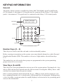
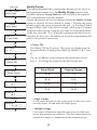
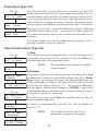
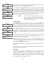
Galaxy 3-144, 3-144C, 3-520, 3-520C User Guide Honeywell Security Table of Contents Table of Contents .............................................................................. iii Compliance and Approvals ............................................................. vii Introduction ...................................................................................... vii KEYPAD INFORMATION ..................................................................... 1 General ................................................................................................................ 1 Number Keys (0 – 9) ............................................................................................. 1 View Keys (A and B) ............................................................................................ 1 Enter Key (ent) ..................................................................................................... 2 Escape Key (esc) .................................................................................................. 2 Hash Key (#) ......................................................................................................... 2 Star Key (*) ........................................................................................................... 2 Power LED ........................................................................................................... 2 Banner .................................................................................................................. 2 User Codes ........................................................................................................... 2 SETTING THE SYSTEM ...................................................................... 3 Before Setting ...................................................................................................... 3 Entering A Pin - User Type 2.1 - 2.2 .................................................................... 3 Entering A Pin - User Type 2.3 - 3.6 .................................................................... 3 Setting groups ..................................................................................................... 3 Exit time ............................................................................................................... 3 Sounder ................................................................................................................ 4 Zones Open .......................................................................................................... 4 Final Door/Terminator ......................................................................................... 4 System Set ........................................................................................................... 4 Part Setting .......................................................................................................... 4 Cancelling The Setting ....................................................................................... 4 Group Name ......................................................................................................... 4 MAX SETTING OPTIONS .................................................................... 5 Setting with User Cards/Tags/Fobs .................................................................... 5 Dual Focus ........................................................................................................... 5 Keyprox ................................................................................................................ 5 UNSETTING THE SYSTEM ................................................................ 6 Normal Entry ........................................................................................................ 6 Straying From the Entry Route ........................................................................... 6 Slow Entry ............................................................................................................ 6 Cancelling Alarms ............................................................................................... 6 Manager Reset ..................................................................................................... 6 Engineer Reset .................................................................................................... 6 Unsetting with the MAX Cards ............................................................................ 6 iii ALERT CONDITIONS .......................................................................... 7 MENU OPTIONS ................................................................................. 8 Full Menu ............................................................................................................. 8 Quick Menu .......................................................................................................... 8 Accessing The Menu ........................................................................................... 9 Full Menu ............................................................................................................. 9 Quick Menu .......................................................................................................... 9 Omit Zones (User Type 2.3 and Above) ............................................................ 10 Purpose ........................................................................................................................ 10 Selecting Omit Zones .................................................................................................. 10 Viewing Eligible Zones ................................................................................................ 10 Omitting Zones ............................................................................................................. 10 Setting With Omitted Zones ......................................................................................... 10 Vibration Zones ............................................................................................................ 10 Atm 1/2/3/4 Zones ........................................................................................................ 11 Forced Set (User Type 2.3 and Above) ............................................................. 11 Purpose ........................................................................................................................ 11 Selecting Forced Set .................................................................................................... 11 Non-omittable Zones ................................................................................................... 11 Chime (User Type 2.3 and Above) .................................................................... 12 Purpose ........................................................................................................................ 12 Selecting Chime .......................................................................................................... 12 Chime In Operation ...................................................................................................... 12 Display Zones (User Type 2.4 and Above) ........................................................ 12 Purpose ........................................................................................................................ 12 Selecting Display Zones .............................................................................................. 12 Address ........................................................................................................................ 12 Function ........................................................................................................................ 12 Status ........................................................................................................................... 13 Description ................................................................................................................... 13 Selecting And Viewing ................................................................................................. 13 Escape ......................................................................................................................... 13 Display Log (User Type 2.4 and Above) .......................................................... 13 Purpose ........................................................................................................................ 13 Selecting Display Log .................................................................................................. 13 Events ........................................................................................................................... 13 Selecting a Date ........................................................................................................... 13 Viewing Each Event ...................................................................................................... 13 Additional Information .................................................................................................. 14 Printing ......................................................................................................................... 14 Print (User Type 2.4 and Above) ....................................................................... 14 Purpose ........................................................................................................................ 14 Selecting Print .............................................................................................................. 14 Codes ........................................................................................................................... 14 Zones ........................................................................................................................... 14 Log ............................................................................................................................... 14 All .................................................................................................................................. 14 Help Message .............................................................................................................. 14 iv Walk Test (User Type 2.5 and Above) ............................................................... 15 Purpose ........................................................................................................................ 15 Selecting Walk Test ...................................................................................................... 15 All Zones ...................................................................................................................... 15 Selected Zones ............................................................................................................ 15 Ending Walk Test ......................................................................................................... 15 Time/Date (User Type 3.6) ................................................................................. 16 Purpose ........................................................................................................................ 16 Selecting Time/Date .................................................................................................... 16 Changing Time ............................................................................................................ 16 Changing Date ............................................................................................................. 16 Advance and Retard ..................................................................................................... 16 Codes (User Type 3.6) ....................................................................................... 17 Purpose ........................................................................................................................ 17 Manager Code ............................................................................................................. 17 Selecting Codes .......................................................................................................... 18 User Codes .................................................................................................................. 18 Modify Pin ..................................................................................................................... 18 Modify Type ................................................................................................................... 19 Modify Name ................................................................................................................ 20 Time Zone .................................................................................................................... 20 Temporary Codes ........................................................................................................ 21 Pin Change .................................................................................................................. 21 Modify Groups .............................................................................................................. 22 Max Number ................................................................................................................. 23 Max Function ................................................................................................................ 24 Max Keypad .................................................................................................................. 24 Forgive Antipassback ................................................................................................... 24 Pin Warning .................................................................................................................. 25 Summer (User Type 3.6) .................................................................................... 25 Trace (User Type 3.6) ......................................................................................... 26 Timer Control (User Type 3.6) ........................................................................... 26 Group Omit (User Type 3.6) ............................................................................... 29 Remote Access (User Type 3.6) ......................................................................... 30 Authorisation Access (User Type 3.6) ............................................................... 31 AVOIDING FALSE ALARMS ............................................................. 32 ZONE REFERENCE TABLES .......................................................... 33 ALARM AND HELP MESSAGES ...................................................... 34 Alarm In Progress ........................................................................................................ 34 Pa Reset Required ...................................................................................................... 34 Manager Reset Required ............................................................................................ 34 Engineer Reset Required ............................................................................................ 34 No Entries .................................................................................................................... 34 Invalid Selection ........................................................................................................... 34 Invalid Code ................................................................................................................. 34 Technistore Reset ........................................................................................................ 34 No Modules Added ....................................................................................................... 34 INSTALLER DETAILS ....................................................................... 35 v vi INTRODUCTION The Galaxy 3 Series alarm system is a microprocessor controlled system which has been designed using the latest software and hardware technology. First and foremost, the Galaxy 3 Series meets all your security needs. The engineer will program and commission the system to your own exacting requirements. Warning: There are no user serviceable parts inside. Please refer all servicing to a qualified installer. Compliance and Approvals Public Switched Telephone Network (PSTN) approval The equipment has been approved to Council Decision 98/482/EC for Pan -European single terminal connection to the Public Switched Telephone Network (PSTN). However due to differences between the individual PSTNs provided in different countries the approval does not, of itself, give an unconditional assurance of successful operation on every PSTN network termination point. In the event of problems contact the equipment supplier in the first instance. The Galaxy is designed to interwork with the following networks: Austria France Italy Norway Belgium Greece Liechtenstein Portugal Denmark Iceland Finland IrelandThe Netherlands Switzerland United Kingdom Luxembourg Spain * Germany Sweden * May have interworking difficulties. NOTE: listed. Contact the equipment supplier before using the Galaxy on any network not vii KEYPAD INFORMATION General The Galaxy Alarm system is controlled by Galaxy Mk7 Full Alpha Liquid Crystal Display (LCD) keypads. A maximum of 16 keypads may be connected to the Galaxy 3-144 control panels. A maximum of 32 keypads may be connected to the Galaxy 3-520 control panels. GALAXY 520 V5.00 08:58 TUE 22 NOV LCD Display Number Keys 1 2 3 A 4 5 6 B 7 8 9 ent Enter Key * 0 # esc Escape Key View keys Star Key Hash Key Power LED Number Keys (0 – 9) These keys are used to enter the code and to select and modify options. Before carrying out operations on the system, users must identify themselves with a Personal Identification Number (PIN). This number is at least a 4 digit number selected from keys 0 - 9. The number keys are also used where groups are programmed on the system permitting groups (areas) to be set or unset. View Keys (A and B) These keys have been programmed to activate one of the system options. Pressing the A > key after a valid code has been entered starts the full set routine. Pressing the < B key after a valid code has been entered starts the part set routine. Once a system option has been selected, the A > or < B keys can be used to operate as view keys, stepping forwards (A >) or backwards (< B) through lists of information. Holding down a view key while viewing an option list, rapidly displays each item in the list, permitting quick access to the information. 1 Enter Key (ent) The ent key accepts and processes entered data. Valid actions are performed and the next option is accessed. Escape Key (esc) The esc key aborts the current option to return to the previous option level. Any option modification made prior to the option being aborted is erased. Successive pressing of the esc key returns the user to the start display (known as the BANNER). The esc key also aborts the setting routine if pressed during the exit time. Hash Key (#) The # key is used to display additional choices for certain options, e.g. ADVANCE/RETARD the time in the Time/Date option. This key is also used as the user duress key (by pressing twice following a valid code entry). Star Key (*) The * key is used to provide additional features for certain options, e.g. printing the event log or deleting entries. Power LED The green power LED remains lit whenever the keypad is connected to a mains power supply. A mains power failure is indicated by the LED flashing slowly. The LED flashes rapidly if the battery voltage falls below the minimum threshold or if one of the fuses on the control panel PCB blows. Banner The banner is the display shown on the keypad, e.g. Galaxy 520 V5.00 (with the time and date on the bottom line). This is shown at all times when the system is unset, unless the menu is being accessed or an alarm or help message is on the display. The banner can be changed by the engineer. In the set condition the banner is normally blank. User Codes The user code is a unique PIN (Personal Identification Number) of at least 5 digits in length. The PIN identifies the user to the Galaxy Alarm panel and allows operation of the system. 2 SETTING THE SYSTEM Before Setting Code + A Code + ent TIMED SET 120 Before setting the system ensure all doors and windows are secured and areas protected by movement detectors are free from obstruction. Entering A Pin - User Type 2.1 - 2.2 As each digit is entered the keypad responds with a bleep and displays a *. When all the digits are entered, press the ent or A > key to start the setting routine. Entering A Pin - User Type 2.3 - 3.6 As each digit is entered the keypad responds with a bleep and displays a *. When all the digits are entered press the A > key to start the setting routine. Code + A Setting groups SET Groups A12345678 UUU----- 1 SET Groups A12345678 SUU----- Where group choice has been assigned to the PIN, select which groups have to set as part of the setting routine. The set status of each group is displayed on the keypad screen. Possible status options are :R = Ready (Groups is unset, and all zones are closed) F = Faulted (Group is unset, and at least one zone is open) S = Set (Group is set) ent L = Lockout (Group is locked out, and cannot be unset) TIMED SET 120 Code + A SET Groups A12345678 USS----- A Key SET Groups B12345678 USS----ent TIMED SET 60 Select which groups have to be to set by entering the number of the group. For example, to set groups 2 and 3 press keys 2 and 3 . The display changes to indicate the groups selected for setting. Pressing the ent key starts the setting routine for the specified groups. The Galaxy 3-520 has more than 8 groups. If the user has group choice, the available groups will be displayed at the keypad following a valid code + A >. The groups will be displayed showing A1 to A8. Use both A > and < B keys to scroll to the various sets of groups. If the user does not have group choice, entering the PIN and A > will cause all groups assigned to the user to set. Exit time If all the system zones are closed when the setting routine is started, the display indicates the remaining time, in seconds, to vacate the premises. Exit the building using the agreed route. 3 Sounder During the setting period the sounder emits a continuous tone if all of the zones are closed. If a zone is opened during the setting period, the sounder begins to pulse. The sounder also pulses during the last 25% of the setting time to indicate time running short. Zones Open The exit time will reset should any zones be open or opened during setting. The display will indicate the number of zones open and invite viewing. Closing the zones will restart the exit time. An alarm will be generated if setting is not completed before the Fail to Set period expires. (Fail to Set; programmed by engineer). 3 zones open [<] [>] to view Note: Before closing the open zone, press esc to abort the setting routine. The ESC TO ABORT message will flash as a reminder. Final Door/Terminator The setting procedure can be manually completed by either closing the FINAL door or by pressing the TERMINATOR button. System Set When time has expired or a manual termination is made, the system waits four seconds before setting. The sounders emit two long tones to confirm that the system is set. The keypad briefly displays the message SYSTEM SET, before returning to the banner. Part Setting PIN + B PART SET 120 To Part Set the system press the < B key after the PIN. Only the zones which have the PART attribute enabled are set. All other setting features are the same. Cancelling The Setting The setting routine can be aborted by pressing the esc key before the system sets. SET Groups * A12345678 RRRRRRRR +# A1 OFFICE AREA R [<] [>] #=CHANGE Group Name Press * and # keys simultaneously when groups are displayed on the keypad (when setting for example), will display the name of the group . The group name should be programmed by the installation engineer. Press the * and # keys to return to the group display. 4 MAX SETTING OPTIONS Setting with User Cards/Tags/Fobs MAX user cards/tags/fobs can be used to set the system. This is done by assigning a MAX user card (tag or fob) with one of the setting options. When the MAX card is held against a MAX module for five seconds, the MAX function is activated. For example, if the MAX function assigned is 13 = Part Set, then activating the card held function results in the system being part set. If a user is assigned group choice, then a keypad will have to be accessed to select the group for setting after swiping the card. Dual Focus If a # is assigned to a particular users pin and their max card number, then the user will have dual focus operation. This means that they will have to enter their pin first, before setting with the max card and vice versa. Keyprox A keyprox is a keypad that has a card reader built in. They are normally installed on systems where dual focus setting and unsetting are used. Keyproxes are used as a keypad and MAX as detailed above, but the card is held against the lower right corner of the keypad as shown in the following diagram: GALAXY 520 V5.00 08:58 TUE 22 NOV 1 2 3 A 4 5 6 B 7 8 9 ent * 0 # esc 5 UNSETTING THE SYSTEM Normal Entry PIN + ent Galaxy 520 V5.00 15.49 MON 18 Nov Unsetting starts immediately when the FINAL door is opened or an ENTRY zone is activated. The sounder pulses slowly and the user must go directly to the keypad and enter a valid PIN, followed by A>, <B or ent. Users with group choice, will access the UNSET screen following PIN entry. This permits the user to unset specific groups. To return to the SET screen press ent. Straying From the Entry Route Go directly to the keypad when entering the building. If the user strays into a protected area and activates a zone, an alarm will occur. The police may be called out and the system will have to be reset. Slow Entry Enter a valid PIN before the entry time expires. If the entry time expires before a valid PIN is entered, then an alarm will occur. The sounder begins to pulse quickly when 75% of the entry time has elapsed indicating time is running short. Cancelling Alarms PIN + ent 4 ALARMS [<] [>] to View CALL MANAGER RESET REQUIRED CALL ENGINEER RESET REQUIRED To cancel an alarm, enter a valid PIN followed by ent at the keypad. The keypad displays details of the zone activated. When more than one zone is activated, details can be viewed using A > or < B. Press ent to return to the banner. Certain types of alarms, once cancelled, require a code with the appropriate reset authorisation to be entered. The system prompts for a valid reset code by displaying Manager Reset Required or Engineer Reset Required on the keypad. Manager Reset Entering a manager type PIN followed by ent, resets the system following an alarm activation. Engineer Reset Certain types of alarm require an engineer to visit the site and, after investigation, reset the system. In such cases, the system cannot be reset until the engineer reset has been carried out. Unsetting with the MAX Cards If any of the groups assigned to the MAX are set, then swiping the MAX module with a card unsets the groups. Group choice and dual focus operation, where implemented will apply as per setting instructions. 6 ALERT CONDITIONS When a fault condition occurs in the unset state, an alert condition is activated. This consists of an intermittent beep at the keypad and/or a visual alert on the keypad. A user should enter their code at the keypad and press ent.The fault or faults will be shown. Use the A>and <B keys to scroll through multiple faults. 7 MENU OPTIONS The Galaxy 3 Series provides various menu options for modifying the functional performance of the system. There are two menu structures: Full Menu Only accessed by authorised users including the master manager code and by the engineer. Quick Menu A selection of options from the full menu. The quick menu is the default menu access for all user codes (type 2.3 and above) except the master manager and engineer. Full Menu User Type Quick Menu Type 2.3 Type 2.4 Type 2.5 Type 3.6 2.3 0 = Omit Zones 10 = Setting 20 = Display 30 = Test 40 = Modify 2.3 1 = Forced S et 11 = Omit Zones 21 = Display Zones 31 = Walk Test 41 = Time/Date 2.4 2 = Chime 12 = Timed Set 22 = Display Log 32 = Outputs 42 = Codes 2.4 3 = Display Zones 13 = Part Set 23 = System 43 = Summer 2.4 4 = Display Log 14 = Forced Set 24 = Print 44 = Trace 2.4 5 = Print 15 = Chime 25 = Access Doors 45 = Timer Control 2.5 6 = Walk Test 16 = Instant Set 46 = Group Omit 3.6 7= Time/Date 17 = Instant Part 47 = Remote Access 3.6 8 = C o d es 18 = Home Set 48 = Access Authorisation 3.6 9 = Summer 19 = All set Table 1. Menu Options 8 Accessing The Menu To access the menu enter a valid code and press the ent key. If there are any outstanding system faults, these will be displayed first. Where there is more than one fault a > symbol will be displayed and the scroll keys can be used to view them. Pressing the ent key again takes the display into the menu. The Full Menu or Quick Menu is accessed, depending on the user type. Note: 1. If the user does not have group choice, all groups assigned to the user code must be unset. 2. If the user has group choice, only the group that the FINAL or ENTRY zone is assigned to in unset. 3. If there are no groups, then the system must be unset. Full Menu The Full Menu has a hierarchy of four structures contained within it. Each structure is accessible by an increased user code type. Quick Menu The Quick Menu offers users type 2.3 and above a selection of up to 10 options, numbered 0 – 9. The required option is selected by entering the option number (0 – 9) or by using the A > or < B keys to display each option. The menu options (as with all Galaxy lists) are circular, therefore menu option 9 is followed by menu option 0. The following Quick Menu options are the factory default settings. Each option is described in the following pages. 9 Omit Zones (User Type 2.3 and Above) Purpose This option allows the user to omit zones before setting the system. Zones must be eligible for omission otherwise they will not be displayed. PIN + ent 0 = OMIT ZONES [ent] to select ent 1003 A1 INTRUDER #=OMIT ENT=SET >A 1004 SECURITY #=OMIT ENT=SET # 1004 SECURITY OMITTED ENT=SET Note: Selecting Omit Zones Enter the QUICK MENU. The 0=OMIT ZONES option is displayed. Press the ent key to select this option. Viewing Eligible Zones When the Omit Zones option is selected the first zone eligible for omission is displayed. The eligible zones can be viewed by pressing the A> or <B keys. The zones eligible for omission can be rapidly viewed by holding down either of these keys. Omitting Zones Once the zone to be omitted is shown on the display, press the # key. The display indicates that the zone is omitted. A> and <B keys can then be used to select other zones to be omitted using the same method. Note: ent 1 OMITTED 120 esc ZONES OMITTED 14:35 TUE 17 DEC Zones remain omitted for one set period only. A zone is omitted from the system as soon as the # key is pressed. The system does not have to be set. Setting With Omitted Zones When the list of omitted zones is complete the setting routine is started by pressing the ent key. The system starts to set and the display indicates how many zones have been omitted. Alternatively the esc key can be used to return to the menu options. Zones that have been omitted remain omitted even after using the esc key. Note: All zones omitted are recorded in the log against the user. Vibration Zones If the omitted zone is a vibration zone, then all zones of this type (in all groups) will be block omitted. The vibration zones remain omitted until manually reinstated. Unsetting the system does not reinstate vibration detectors. 10 ATM PIN + ent [ent] to Select 1=ATM-1 >A [ent] to Select 2=ATM-2 ent DELAY ACCESS ATM-2 12 mins ACCESS TIMEOUT ATM-2 10 mins Atm 1/2/3/4 Zones ATM zones are omitted by entering one of the ten ATM codes (last 10 users). To select this option enter an ATM code followed by the ent key. Use the A> key to scroll through the four ATM zone options (ATM1 to ATM4) and select by pressing the ent key. A preprogrammed ATM delay time will expire before omitting all ATM zones with the selected ATM zone type. The zones will be omitted for the duration of the ATM time-out period and the remaining time in minutes will be displayed on the initiating keypad. A warning is given ten and five minutes before the zones are reinstated. The ATM Time-out period can be extended by entering an ATM code and selecting 1=Reset Access. To manually reinstate ATM zones, enter an ATM code and select 2=Abort Access. ATM PIN + ent 1=RESET ACCESS 2=ABORT ACCESS 1 Forced Set (User Type 2.3 and Above) ATM PIN + ent 0 = OMIT ZONES [ent] to Select 1 1 = FORCED SET [ent] to Select ent 3 OMITTED 120 Purpose When enabled, the Forced Set option allows the user to automatically omit zones, eligible for omission, which are open when the system setting routine is started. Zones omitted in this way remain omitted for one set period only. Selecting Forced Set Access the QUICK MENU. Press key 1 followed by the ent key. The display indicates how many zones have been omitted and the number of seconds left before setting. Non-omittable Zones Some open zones may not be eligible for omission from the system. In this case the display indicates which zones are open and the exit time is reset. These zones must be closed before setting can continue. 2 zones open [<] [>] to View 11 Chime (User Type 2.3 and Above) PIN + ent 0 = OMIT ZONES [ent] to Select 2 2 = CHIME [ent] to Select ent CHIME MODE 0 = OFF >A CHIME MODE 1 = ON ent Purpose The Chime mode is switched on and off by this option. When the Chime mode is on, any zones that have been programmed by the engineer for chime will activate momentarily when opened. Note: Your system may not require any zones of this type. Selecting Chime Enter the QUICK MENU. Press key 2 followed by the ent key. The display shows the ON/OFF status of the Chime mode. Press the >A key to toggle between the states and press the ent key to accept the selection. Note: Keys 1 AND 0 can also be used to select ON and OFF respectively. Chime In Operation When switched ON, the Chime mode remains active until switched OFF again. Zones that have been programmed with the chime attribute by the engineer continue to chime when they are activated. Note: The Chime mode is suspended while the system is set or during an alarm. Display Zones (User Type 2.4 and Above) PIN + ent 0 = OMIT ZONES [ent] to Select 3 3 = DISPLAY ZONES [ent] to Select ent 1001 INTRUDER COMPUTER ROOM Purpose This menu option provides the user with a method of accessing the Display Zones mode and checking each zone for its description and current status. Selecting Display Zones Enter the QUICK MENU. Press key 3 followed by the ent key. Details of the first zone (1001) are displayed. Address The zone address provides a unique four digit address number used for identification and selection, e.g. 1026 - line 1, RIO 02, zone 6. Function The zone function is displayed and identifies the operation of the zone, e.g. INTRUDER, FIRE. 12 Status The current status of the zone is displayed as circuit information, e.g. Open or Closed. This information alternates with function information. Description The zone description, if programmed, is displayed on the bottom line of the display. The descriptor is assembled from alpha-numeric text and describes the zone in detail, e.g. West Office Door. 1001 INTRUDER COMPUTER ROOM 2+1 1021 SECURITY CASHIER DOOR esc Selecting And Viewing Selecting the Display Zones option displays the first zone address available on the system. Other zones can be viewed sequentially by using the >A or <B keys. Zones can also be displayed by entering the address of the zone: enter the line, RIO and zone number (4 digits). Press the # key to display the circuit resistance in ohms and RIO voltage (if hardwired). Escape The esc key aborts the option and returns to the option menu. Display Log (User Type 2.4 and Above) PIN + ent 0 = OMIT ZONES [ent] to Select Purpose The Display Log option provides the user with a means of viewing the system history. Events are recorded in detail and stored in the nonvolatile memory. 4 4 = DISPLAY LOG [ent] to Select ent LOG Groups A12345678 NN-----1+2 LOG Groups A12345678 YY-----ent 08:53 TUE 22 NOV AC FAIL-RIO108 B (hold) MON 21 NOV 1999 MON 20 NOV 1999 Selecting Display Log Enter the QUICK MENU. Press key 4 followed by the ent key. Details of the most recent event to be logged are displayed. Events The events available for display include details of setting, unsetting and alarms. Each event is timed and date stamped. Selecting a Date Hold down one of the view keys, the dates held in the log are rapidly stepped through. The A> key moves forward through the dates and the <B moves backwards. Stopping at the required date reveals the first event for that date. Viewing Each Event The entire events of any one date can be viewed by progressively stepping through the events using the A> and <B view keys. * If the user has group choice enabled, the groups will display. Events for each group can be displayed by entering the group number. release B 13 release <B 16:31 SUN 20 NOV FULL SET USR 98 * # 16:31 SUN 20 NOV KOO L6 A1------esc Additional Information The # key can be used to reveal additional information on some types of events. This information is displayed on the bottom line. The information includes details such as zone descriptors, user types and which keypad was used. Printing If a serial printer is connected to the system, a system history can be printed by pressing the * key. The system will print from the event on display until the most recent event. Print Print (User Type 2.4 and Above) PIN + ent 0 = OMIT ZONES [ent] to Select 5 5 = PRINT [ent] to Select ent 1=CODES 2=ZONES 3=LOG 4=ALL Purpose The Print option gives the user the opportunity to get a hard copy print-out of the system details. This option requires a serial printer to be connected to the system. Selecting Print Enter the QUICK MENU. Press key 5 followed by the ent key. The system print options are displayed. Pressing the esc key aborts the PRINT option. Codes Press key 1 to start the print-out of all the codes, giving the user number, name, level and length of code. 1 PRINTING CODES ESC to abort 2 PRINTING ZONES ESC to abort 3 PRINTING LOG ESC to abort 4 PRINTING ALL ESC to abort PRINTER off-line ESC to abort Zones Select the Zones option to print-out the details of each zone in the system. The zone address, function, and descriptor is printed. Press key 2 to select this option. Log The entire LOG can be printed out by selecting key 3. The print-out consists of up to 1000 events depending on panel type, and details the time and date of setting, unsetting and alarms. All All the options (CODES , ZONES, and LOG) can be printed out by selecting the ALL option. Pressing key 4 delivers a print-out starting with user codes. Help Message If a print-out is started without a printer being connected and on-line, the display indicates that the printer is off-line. 14 Walk Test (User Type 2.5 and Above) PIN + ent 0 = OMIT ZONES [ent] to Select 6 6 = Walk Test ent to select ent 1=TEST ALL ZONES 2=SELECTED ZONES 1 WALK TEST ACTIVE ESC to abort Purpose The Walk Test option provides a method of testing the zones to ensure that they are operating correctly. There are two options available: 1. All zones can be tested 2. Selected zones can be tested In both cases the sounder indicates an open zone. The test is recorded in the log. Wire-free zones also show the received signal strength as a percentage Selecting Walk Test Enter the QUICK MENU. Press the key 6 followed by the ent key. When Walk Test is selected, Test All Zones or Selected Zones displays. All Zones Choosing All Zones (press key 1) starts the test immediately. No selection is necessary as all valid zones are included in the test. The sounder operates whenever a zone is opened and stops when all zones are closed. NO ENTRIES Note: 2 1001 FINAL #=TEST ENT=START >A 1002 EXIT #=TEST ENT=START Selected Zones Choosing the Selected Zones option by pressing key 2 displays the first zone on the system. Each zone is displayed in turn by using the >A or <B keys. When the zone to be included in the test is displayed, press the # key. Other zones can be included in the test in the same manner. When all of the required zones have been selected, press the ent key to start the Walk Test. Note: # 1002 EXIT TEST ENT=START The Test All Zones option only tests zones which can be omitted from the system. The Selected Zones option includes non-omittable zones. Ending Walk Test To abort the walk test option press the esc key, otherwise the walk test option remains active for 20 minutes after the last key press. ent 15 Time/Date (User Type 3.6) PIN + ent 0 = OMIT ZONES [ent] to Select 7 7 = TIME/DATE [ent] to Select ent 15:25 01/03/05 A=TIME B=DATE A> <B NEW TIME --:-HH:MM enter time NEW DATE --/--/-- DD/MM/YY enter date 15:25 01/03/05 A=TIME B=Date # Purpose The Time/Date option allows the user to modify both the time (hours/ minutes) and the date (day/month/year). Selecting Time/Date Enter the QUICK MENU. Press key 7 followed by the ent key. Once the Time/Date option has been selected, the time or date can be selected by pressing the A> or <B key. Changing Time To change the time press the A> key. The display prompts for a New Time in hours and minutes (HH:MM). When the new time is entered, the display immediately returns to the time or date selection screen. The system does not accept invalid times (greater than 23 hours, greater than 59 minutes). Pressing the esc key aborts the entry. Changing Date To change the date press the < B The display prompts for a New Date in days, months and years (DD/MM/YY). When the new date is entered, the display momentarily shows the day of the week, before returning to the time or date selection screen. The system does not accept invalid dates (e.g. 32/13/99). Pressing the esc key aborts the entry. Advance and Retard It is possible to advance and retard the time to compensate for any variations in clock speed. Press the # key when in the time/date mode to select the clock speed adjustment. The range is 0 to 120 seconds per week. Pressing the * key will retard the time. Adjustment/week 010 (0-120) secs * (press the * key to retard time) 16 Codes (User Type 3.6) PIN + ent 0 = OMIT ZONES [ent] to Select 8 8 = CODES [ent] to Select ent CODES 1 = User Codes >A CODES 2 = PIN Warning Purpose The Codes menu option enables the managers, (user type 3.6), to assign, modify and delete the codes that allow users to operate and access the system. The codes option is divided into two sub–menus: 1. User Codes Sub divided into 10 menus (depending on whether the group and MAX Mode options are enabled) that determine all of the access information for users with Personal Identification Numbers (PINs). This menu also assigns MAX details to user numbers. 2. Pin Warning This option determines the warning period given to users prior to the programmed Pin Change date. Note: The valid period for Pin Change codes is programmed by the installation engineer. Manager Code The manager code is authorised to: • Program the USER CODES option for each of the user codes. • Allocate other codes to manager type 3.6. • Modify the manager PIN (the manager PIN cannot be deleted) • Assign the MAX features to the code. The manager code defaults to group choice when groups are enabled. The manager is able to toggle the group choice option on and off (using the * key) as required. The manager code defaults to accessing the quick menu. Note: The MAX is the Proximity Access Reader which can be connected to the Galaxy system. This also refers to the MAX3, the enhanced version of the MAX. 17 PIN + ent 0 = OMIT ZONES [ent] to Select 8 8 = CODES [ent] to Select ent CODES 1 = User Codes ent 001 USER L3 ent [ent] to Select 1 = Modify PIN ent 001 PIN > 5678 ent 001 PIN > #5678 Indicates Dual Code 001 USER L3 Selecting Codes Enter the QUICK MENU. Press key 8 followed by the ent key. User Codes When the Codes option has been selected, press key 1 to access User Codes. Display each of the user numbers using key A>. Each user number offers options for PIN, level, name and where applicable time zones and groups. When the user number to be modified is displayed, press the ent key to access the Modify Pin option. Modify Pin The Modify Pin option allows a pin to be assigned to a user or an existing PIN to be modified. The PIN must be a four, five or six digit number that is unique to the system. If a duplicate PIN is assigned, the message Duplicate Entry is displayed. As each digit is entered it appears on the bottom line of the display. Pressing the * key erases the last digit displayed. Continued pressing of the *key will erase all of the digits. When the correct PIN has been assigned press the ent key to accept the programming and return to the previous menu level. When a PIN has been assigned to a user number, a solid box () is displayed on the line of the user number details screen. • Deleting a Pin Existing PIN entries can be completely erased using the * key instead of a digit entry. When there is no PIN assigned to a user number a hollow square () is displayed in the top line of the users details screen. • Assigning Dual Codes To program a user code as a Dual Code press the # key while theModify PIN option is selected. The # displays at the start of the assigned user PIN e.g. #5678. When a PIN has been assigned as a dual code two solid boxes () are displayed in the top line of the users details screen. • Dual Codes Operation Entry of a single dual code cannot gain access to the menu, set or unset the system. The message NO ACCESS – ADDITIONAL CODE is displayed. A second dual code must be entered within 60 seconds to access the menu, set or unset the system. Dual codes can be of different levels. The highest level code entered determines the access level to the system. A single entry of a dual code, without a second dual code entry within 60 seconds, results in an Illegal Code record in the EventLog. All outputs programmed as Illegal Code are activated. 18 PIN + ent 0 = OMIT ZONES [ent] to Select 8 8 = CODES [ent] to Select ent CODES 1 = User Codes ent 001 USER L3 Modify Type Each user is assigned an access type which determines the menu options available to the user (see p.7, Table 1. Menu Options). On selecting this option, enter the type to be assigned to the user and press the ent key to accept the programming and return to the previous menu level. See Table 2. User Access Levels, for access availability. EN50131-1 L evel Type Access Availability 1 1.0† Guard 2 2.1† Cleaner Entered into event memory – no other option Can only set the system 2 2.2† Caretaker Can only set and unset the system 2 2.3 Users Menu options 11 - 19 2 2.4 Users Menu options 11 - 29 2 2.5 Users Menu options 11 - 39 2 3.6‡ Manager Menu options 11 - 49 3 3.7‡ Engineer Menu options 11 - 71 3 3.8‡ Remote Menu options 11 - 71 † ‡ No access to menu functions The manager, engineer and remote codes (the last three codes on the system) have fixed types which cannot be reprogrammed. ent Table 2. User Access Levels [ent] to Select 1 = Modify PIN >A [ent] to Select 2 = Modify Level ent 001 Level >_3 • Duress Code If the # key is pressed while Modify Level is accessed, then the current code is assigned as a Duress Code. There is no limit to the number of codes which can be assigned as Duress. Entering a duress code at any time activates outputs programmed as Duress or PA. Any valid PIN followed by # # ent (the ent key can be replaced by either the A> or <B key) can be used as a Duress Code. ent 19 PIN + ent 0 = OMIT ZONES [ent] to Select 8 8 = CODES [ent] to Select ent CODES 1 = User Codes ent 001 USER L3 A1_______ ent [ent] to Select 3 = Modify PIN 3 [ent] to Select 3 = Modify Name >A ent 001 NAME USER_ EFG HIJKLMNØö0 P ent • Quick Menu All user codes default to the quick menu. This menu is made up of a selection of ten options (0 – 9) from the menu options 11 – 49. The user code type controls access to the quick menu. Any user can be upgraded from the quick menu to the full menu by assigning a * to the user while the Modify Level option is accessed. Therefore a user with a type *2.5 would have access to the full menu from options 11 – 32. No code can access both menus. Note: The master manager code defaults to the full menu. Modify Name This allows a name to be assigned to the user (maximum 6 characters). Each of the user codes default to the name USER and the manager defaults to MGR. The manager name cannot be changed. On selecting the Modify Name option, a section of the alpha-numeric that can be assigned to the user name is displayed on the bottom line of the keypad; the cursor flashes on the letter L. Press * to erase the letters of the default or previous name. When the previous name has been erased, use the A> or <B keys to move the cursor to the first letter of the name and press the ent key. The selected character appears on the top line, continue this process until the name is completed. The # key toggles between upper and lower case characters and the system library. Press esc to save the name and exit. Time Zone Managers can allocate time zones to user PINs when TIMERS have been programmed by the engineer. Time zones are used to disable the user PIN during the times (ON to OFF) programmed in TIMER A and B. When 4 = TIME ZONE displays, press the ent key . Using the A> key select the time zones option to be allocated to the PIN. The following time zones options are available: [ent] to Select 4 = Time Zone ent [ent] to Select 0 = OFF Use the A key to step through the four time zone options. ent 0=OFF 1=TIMER A 2=TIMER B 3=TIMER A+B The times assigned to Timer A and Timer B can be viewed using option 45 Timer Control. No access will be granted if a code, assigned to 1=Timer A, 2=Timer B or 3= Timer A+B is entered out with the assigned times, an Illegal Code event is recorded in the log and any outputs programmed as Illegal Code are activated. 20 Temporary Codes Temporary Codes allow a PIN to be temporarily allocated to a user. On selecting this option, enter the number of days (0 – 99) that the code is to remain active. The default setting of 0 indicates that the code is permanent. A temporary code expires and is removed from the codes list at midnight after the assigned number of days. A code that has been assigned as a Temporary Code is indicated on the user code display by a ^ between the user number and the user name, e.g. 001^ USER. PIN + ent 0 = OMIT ZONES [ent] to Select 8 8 = CODES [ent] to Select ent Note: CODES 1 = User Codes The manager, rngineer or remote codes cannot be as signed as a Temporary Code. Pin Change To program a user code as a PIN Change code, select the Temporary Codes option and press the * key instead of a number of days for a temporary code. Press the ent key to accept the programming and return to the previous menu level. A code assigned as a PIN Change code is indicated on the user code display by a * between the user number and the user name, e.g. 001 * USER. If a user is assigned the PIN Change feature in the Temporary Code option, the user must assign a new PIN after a predetermined period of time otherwise the PIN expires and is no longer operational. A notification (1 – 28 days) that the PIN requires to be changed can be assigned using the PIN Warning option. This prompts the user to assign a new code whenever the expiring code is entered during the PIN Warning period (except during system unsetting). The new PIN must be four to six digits long and must be different from any current PIN. The new PIN must be re-entered and if confirmed, returns the user to the banner. If the esc key is pressed or the new PIN entered is invalid, the user may continue to use the panel as normal. The next PIN entry will prompt the PIN change. ent 001 USER L3 ent [ent] to Select 1 = Modify PIN 5 [ent] to Select 5 = Temp Code ent Temp Code 00 (0-99) days 2+5 Note: Temp Code 25 (0-99) days If the user has not entered a new PIN by the end of the PIN Warning period, then the PIN is erased on the next unsetting of the system. ent * Temp Code (0-99) days PIN Change Code ent 21 PIN + ent 0 = OMIT ZONES [ent] to Select 8 8 = CODES [ent] to Select ent CODES 1 = User Codes ent 001 USER L3 A ________ Modify Groups This option determines the system groups that the user has access to and operational control over. The Modify Groups option is only available when the Group Mode has been enabled by the engineer. The system defaults to groups disabled. Groups allocated to the user are displayed when the Modify Groups option is selected. All users default to Group 1. Pressing the group number toggles the group assigned to the user. e.g. Pressing 2 and 3 assigns Groups 2 and 3 to the user. Pressing 1 (while group 1 is already assigned) removes group 1 from the user code. To assign group choice to the user, press the * key. When the required groups have been assigned to the user, press the ent key to accept the programming and return to the previous menu level. • Galaxy 520 The Galaxy 520 has 32 groups. The groups are displayed on the keypad in blocks of eight groups which are labelled A, B, C and D: ent [ent] to Select 1 = Modify PIN Use A> or <B keys to move between the group blocks. Press keys 1 – 8 to assign the groups in each block to the user. 6 [ent] to Select 6 = Modify Groups ent Groups A 1_______ >A 1_______ >A Group Block Physical Groups A1-8 1-8 B1-8 9-16 C1-8 17-24 D1-8 25-32 Groups B 1_______ >B 1_______ 1+2+3 Groups B 1_______ >B _23_____ • Single Groups A user can be assigned to any single group. In this case a user can only access, set and unset the single group. • Multiple Groups Users can be allocated to more than one group in which case access and operation are collective. The user cannot choose to operate on a single or combination of the assigned groups. 22 * Groups B 1_______ >B Ú23_____ ent • Group Choice Users can be allocated to more than one group, but also have the choice of which of the allocated groups to view, set or unset. Pressing * key while assigning groups to the user assigns the group choice feature. Notes: 1.The manager has fixed access to all system groups. This cannot be reprogrammed. 2.The manager is assigned group choice by default, but the feature can be removed. 3.Users authorised to access the Codes option can only assign groups that have been assigned to their user code. A user who does not have access to group 4, cannot assign group 4 to another user code. PIN + ent 0 = OMIT ZONES [ent] to Select 8 8 = CODES [ent] to Select ent CODES 1 = User Codes ent 001 USER L3 A ________ Max Number Each MAX card/tag/fob has a unique 10 digit number laser etched onto it. A MAX card/tag/fob is assigned to a user by entering this number in the Max No option. The number identifies the MAX card/tag/fob to the system and references it to the user it has been assigned to. 1. Enter the unique 10 digit number which is laser etched onto the MAX card or enter the unique RF keyfob button identifier generated by the RF RIO or press the A and 1 keys simultaneously of the KeyProx and present the card/fob to the KeyProx reader within 5 seconds. The decrypted number in the card will be self learned onto the Galaxy panel and is displayed on the KeyProx.. 2. Press the ent key to save the programming and return to the previous menu. ent [ent] to Select 1 = Modify PIN 7 [ent] to Select 7 = MAX No ent MAX No > Enter new MAX number Note: A MAX number can be assigned to a user code that does not have a PIN allocated to it. All other options for this user are valid for the MAX card/tag/fob. It is recommended that MAX numbers should be assigned to users not requiring a PIN at the Max Users menu option. When a MAX number has been assigned to a user number, a lower case (m) is displayed on the top line of the user number details screen. A # assigned to the max number makes the max function dual focus, ie it needs the pin entered first. A star * assigned to the max number makes the card dual access, ie it needs another card to open doors. ent 23 PIN + ent 0 = OMIT ZONES [ent] to Select Max Function The MAX card can be assigned to a single menu option. The user must be authorised to access the menu option, either by the user level assigned or by having the menu option access type changed by the engineer. 8 8 = CODES [ent] to Select ent CODES 1 = User Codes ent 001 USER L3 A ________ ent [ent] to Select 1 = Modify PIN 9 8 [ent] to Select 8 = MAX Function ent MAX Function = NOT USED ** 1+2 (A>) MAX Function 12 = TIMED SET The default option is Not Used. A new option is assigned by scrolling using the A> or <B keys until the required option is displayed or directly entering the option number using the keypad digits. Select the function by pressing the ent key Max Keypad The menu option assigned to the MAX card/tag/fob can be limited to operate on a single keypad. On selecting this option the display shows **, indicating that a keypad has not been specified. To specify a keypad, press the # key. The address of the first keypad on the system is displayed. Use the A> or <B key to select the required keypad and press the ent key to accept the programming. Note: A black flashing square over the first digit of the keypad address indicates the address of the keypad currently being used. • “Card- Held” Max Operation The MAX function is activated when the card is held directly in front of a MAX reader for three seconds. The MAX reader must be assigned a common group to the MAX user. The keypad specified in the Max Keypad option displays the assigned MAX function. ent [ent] to Select 9 = MAX Keypad ent - KEYPAD ** # = Enable # 01 - KEYPAD # = Disable A> 02 - KEYPAD # = Disable ent Note: If the specified keypad is in use, then the option does not display. If the MAX function is an “action” type option, e.g. 12 = Timed Set, then the function is carried out. If no keypad is specified (**), the MAX menu option will operate on all keypads that share the groups of the MAX user. If there is more than one keypad, the message Press any key is displayed on all valid keypads. Press any key to activate the function on that keypad. Press no key within five seconds and the function automatically activates on all keypads. Forgive Antipassback When the Timed Antipassback feature is enabled, it will prevent more than one use of any particular card at a particular reader within a preset time period. The forgive function is available to clear all or particular antipassback restrictions in force. 24 Pin Warning This option determines the number of days notification before the expiry date of any user codes programmed as PIN Change. During the notification period, the user is prompted to enter a new code on entry of the expiring PIN. The default period is 99 days, with a programmable range of 1 – 99. If a user does not assign a new code by the end of the PIN Warning period, then the code is erased on the next unsetting of the system. PIN + ent 0 = OMIT ZONES [ent] to Select 8 8 = CODES [ent] to Select ent CODES 1 = User Codes Note: >A The PIN Warning ends on the last day of the month, the PIN expires on the first day of the following month. CODES 2 = PIN Warning ent PIN Warning 28 (1-28) days Summer (User Type 3.6) PIN + ent On the first day of each year, the British Summer Time (BST) Start date is set to the last Sunday in March and the End date is set to the last Sunday in October. 0 = OMIT ZONES [ent] to Select 9 9 = SUMMER [ent] to Select ent A=START B=END 26 MAR 29 OCT A> B< NEW DATE --/-- 2+3+0+3 DD/MM 2+7+1+0 23 MAR 29 OCT A=START B=END esc The operation of the Summer option is as follows: At 01 : 00 hours on the Start date, the system clock advances to 02 : 00 hours. At 02 : 00 hours on the End date, the system clock goes back to 01 : 00 hours . Note:The time always changes with reference to GMT. For example, Italy which is + 1 hour would be: Last Sunday in March - 02.00 to 03.00 Last Sunday in October - 03.00 to 02.00 The Start and End dates can be reprogrammed by authorised user codes. Press the A> key to modify the Start date or the <B key to select the End date. The new date must be a valid four digit number in the day month format (dd/mm). 26 MAR 27 OCT A=START B=END esc 25 Trace (User Type 3.6) PIN + ent 44 = TRACE [ent] to Select 01:04 1064 Sun 01 Jan Intruder 09:30 UNSET Sun 01 Jan MGR This option provides a record of the most recent alarm activation. The Trace option records the details of the setting and unsetting of the system immediately before and after the alarm activation and the first 5 events occurring during the alarm activation. This information is maintained in the trace until the next alarm activation. On entering the option pressing the A and B keys steps through each of the 7 trace entries. Pressing the # key while viewing the Trace option displays additional information about certain events — user events reveal the keypad, user level and current group; alarm events reveal the zone descriptor if programmed. The currentt display trace can be printed out by pressing the pressing the esc key aborts the print-out. key; Timer Control (User Type 3.6) PIN + ent 45 = TIMER CONTROL [ent] to Select 1=View This function allows the programmed times in each of the timers to be viewed and switched on and off as required. Use the A and B keys to scroll through each of the programmed times. NOTE: [ent] to 1=View The programmed times cannot be modified using this option. Select [ent] to Select 1=TIMER A A MON ON 19:30 TUE OFF 07:30 PIN + ent 45 = TIMER CONTROL [ent] to Select [ent] to Select 2=Holidays [ent] to Select 1=Modify Dates 2=Holidays This function allows up to 10 holiday periods to be allocated. A Start and End date is entered for each holiday period using the 1=Modify Dates option. On selecting this option, the Start and End dates for holiday period 01are displayed. If no dates have been entered for this period, then the display will show **/**. To program the Start date, press the ent key; the date display changes to >DD/MM< ; enter a valid 4 digit number and press the ent key to accept the selection. The year is not required, only the day and month. Press the # key to move to the End date and follow the procedure for programming the Start date. To remove a programmed date, press the * key. The date display returns to **/**. NOTE: The holiday periods can only be programmed by managers and engineers 01:START >DD/MM 01: END DD/MM 26 PIN + ent 45 = TIMER CONTROL [ent] to Select [ent] to Select 2=Holidays [ent] to Select 2=Assign groups STATUS A12345678 Groups YNYYYYYN PIN + ent 45 = TIMER CONTROL [ent] to Select [ent] to Select 3=Early Open [ent] to Select 1=Early Times Early Open HH:MM The groups that are affected by the programmed holiday period are assigned using the 2=Assign groups function. On selecting the Assign Groups option, the groups currently assigned to the programmed holiday periods are indicated by a Y below the group; an N is displayed below the unassigned groups. All groups default to Y. Pressing the group number toggles the group status. When the required groups have been assigned to the holidays, press the ent key to accept the programming and return to the previous menu level. NOTE: The Galaxy 3-520 has more than 8 groups; these are displayed on the keypad in blocks of eight groups. Press A or B keys to display each of the group blocks. 3=Early Open If the Early Open option (45.3.2) is enabled, the Lockout OFF time for the following day is brought forward by the number of minutes (0 – 240) programmed by the engineer. This allows the system to be manually unset earlier than normal. There are 2 functions within this option: The 1=Early Times function displays the time that the system can be manually unset on the following day; this time is the Lockout OFF Time minus the Early Open period and is displayed in the 24 hour format. If groups have been enabled, the early opening time for each of the groups enabled for early opening in the Early Open option can be viewed by pressing the A or B keys This function only displays the early time if the Early Open option is enabled; if this option is disabled or if no groups have been enabled, the message NO ENTRIES is displayed. The 2=Early Open function permits early opening to be disabled or enabled. If groups have been enabled, then the groups can be individually enabled to permit early opening. 4=Timers This option allows Timer A and Timer B to be switched on and off as required. If a Timer is set to off, the operation of the Timer is suspended; this option cannot be used to alter the programmed times. Both timers default to 0 = Off. To switch the timers on, select the required timer and change the setting to 1 =On. 27 5=Late Work The Late Work option authorises an Autoset Extension in advance of the prewarning period. PIN + ent 45 = TIMER CONTROL [ent] to Select 6=Weekend Work The Weekend Work option unsets the system at the weekend. If the Weekend Day is programmed other than 0 = OFF (default), on the next occurrence of the programmed Weekend Day, the Timers adopt the times they have on the assigned Pattern day. For example, this allows a Sunday to use the Autoset and Lockout Timers of a Monday. NOTE: [ent] to Select 6=Weekend Work [ent] to Select 1=Program Days [ent] to Select 1=Weekend Day [ent] to Select 1=SAT A to view Parameter 41 = Weekend Work must be enabled (default is Disabled) to allow the Weekend Day to be selected by the user. On selecting the 1=Weekend Day option the programmed Weekend Day is displayed; the default is 0 = OFF. Use the A or B keys to select the required day or days and press the ent key to accept the programming and return to the previous menu level: 0 1 2 3 = = = = OFF SAT SUN BOTH (Saturday and Sunday) The selected Weekend Day remains active for one occurrence only. The Weekend Day returns to the default of OFF immediately following the assigned day. The Weekend Day must be allocated each time the function is required. On selecting the 2=Pattern Day option the user is shown the programmed timers that are effective when the Weekend Day option is selected. The timers of the selected Pattern Day (Mon to Fri) are adopted by the days selected for the weekend work. NOTE: The Pattern Day can only be allocated by the engineer. 28 Group Omit (User Type 3.6) This option allows a type 3.6 type code to block omit all the omittable zones that are open at the end of the confirm time in a group or multiple groups. All zones in the required groups that have the omit attribute enabled are omitted when this option is selected. Groups can be omitted and reinstated without setting and unsetting the system. On selecting the Group Omit Option the groups assigned to the user code and keypad are displayed as well as the omit status of each group (Y below the group indicates that it is omitted, N indicates that it is not omitted). To omit a group, press the required key. The letter beneath the group number changes from N to Y. To reinstate the group press the key to toggle from Y to N. NOTE: The type 3.6 user must have group choice to enter Group Omit. NOTE: The zones in the selected groups are omitted from the system as soon as the group is selected. On returning to the banner the keypad displays the message ZONES OMITTED. Omitted zones remain omitted for one set period only or until they are manually reinstated to the system. 29 Remote Access (User Type 3.6) This menu option allows control of remote servicing connections. Remote servicing is a procedure which allows the installer to service the alarm system remotely via a phone line or similar connection. The 1=Service option enables the user to control the access mode of 47 = REMOTE ACCESS the remote servicing package. There are 4 communication devices available. [ent] to Select PIN + ent [ent] to 1=Service Select [ent] to Select 0=INT TELECOMS [ent] to Select 0=Direct Access PIN + ent 47 = REMOTE ACCESS [ent] to Select [ent] to 1=Service Select [ent] to Select 0= INT TELECOMS [ent] to Select 1=Call back-1 0=INT TELECOMS 1=ISDN 2=ETHERNET 3=EXT TELECOMS Choose the appropriate device as per the system setup. The user has 2 further options to choose from: 0=Direct Access - On selecting this option, a 40 minute access period is enabled on the Galaxy panel; remote servicing software can directly access the system during this period. Once access to the panel has been gained, it can be maintained indefinitely; there is no maximum duration. On terminating the remote servicing connection to the panel, the access period remains valid for an additional 15 minutes. 1=Call back-1-5 When the user selects one of the numbers (1 – 5) followed by the ent key, the Galaxy panel dials out to the preprogrammed telephone number associated with the Call Back number. If the number selected does not have a preprogrammed telephone number, the system prompts for a number 1 to be entered. Enter the required telephone number and press the ent key; the panel then dials out to the telephone number entered. NOTE: The PC that the panel is dialling to must have remote servicing software running in the Waiting for Call-Back mode. C >_ 30 Authorisation Access (User Type 3.6) This option allows access to be authorised to managers in order to add/ delete/change all user codes. This option can only be enabled by the authorisation code (54321 by default). 31 AVOIDING FALSE ALARMS False alarms are inconvenient and may be costly. Police can withhold response from consistent offenders. Here are nine points to help avoid false alarms. 1. Be sure you fully understand how to operate the alarm system. In your absence someone thoroughly instructed, should be available to operate the system. 2. Before leaving the premises ensure that all doors and windows are securely closed. 3. Where passive infra red or movement detectors are installed make sure the areas are kept free from all animals or birds. Particular attention should be paid to swinging signs, fluorescent lights, Christmas decorations, electric fans, heating or ventilating systems. These should be switched off if possible 4. Always follow the exit/entry route procedure agreed with your alarm installer. 5. Treat the alarm components with care to ensure they are not damaged. 6. Consult your alarm installer about changes to your building and its contents if you think they may affect the alarm system or its performance. 7. Always report alarm activation to your alarm installer. If necessary, an engineer will be sent to check the system. 8. If opening or closing times are monitored by a central station be sure you notify them of any variations from the agreed times or password. 9. The system should be fitted with a stand-by battery (not included) which will operate the system for a limited period in the event of a mains failure. Please ensure that the mains is restored as quickly as possible so that the stand-by battery can be recharged. 32 ZONE REFERENCE TABLES Zone Function Description Chime Omit Part 1001 1002 1003 1004 1005 1006 1007 1008 1011 1012 1013 1014 1015 1016 1017 1018 RIO Zone Function Description Chime Omit Part Function Description Chime Omit Part 1 2 3 4 5 6 7 8 RIO Zone 1 2 3 4 5 6 7 8 33 ALARM AND HELP MESSAGES ALARM IN PROGRESS Alarm In Progress The system is currently in alarm condition and must be cancelled by a valid PIN or keyswitch operation. Pa Reset Required PA RESET REQUIRED After a PA (Personal Attack) zone has been activated, the system has to be reset by a high level code (such as a manager or engineer depending on the reset level setting). Manager Reset Required CALL MANAGER RESET REQUIRED Following an alarm activation, the system requires to be reset by a manager level code. This message is displayed when a tamper alarm occurs. Engineer Reset Required CALL ENGINEER RESET REQUIRED The system has been programmed for engineer reset following an alarm activation. The engineer must be called to reset the system before the user can set the alarm.Tamper alarms usually require an engineer to visit the site to check all modules on the system. No Entries NO ENTRIES INVALID OPTION This message appears if a user attempts to view or inspect the log and there is nothing in the log to be viewed or when the omit option is selected and there are no omittable zones on the system. Invalid Selection The option selected or value entered is illegal or out of range. Invalid Code Invalid code The code entered is not a valid code registered in the system memory. Option Not Available Option not available This option is provided by the engineer, where it is specifically required. Attempting to select an option when it has not been provided results in the display of Technistore Reset CALL ALARM CO. QUOTE CODE XXXXX Call the Alarm Monitoring Station and quote the five digit number displayed. Enter the number quoted by the monitoring station to reset the system. No Modules Added NO MODULE ADDED ESC TO CONTINUE When exiting Engineer Mode the panel does not detect the change in the number of modules. Press esc to continue. 34 INSTALLER DETAILS Name: ----------------------------------------------------------------------------------Address: --------------------------------------------------------------------------------------------------------------------------------------------------------------------------------------------------------------------------------------------------------------------------------------------------------------------------------------------------------------Telephone: -----------------------------------------------------------------------------Office Hours: --------------------------------------------------------------------------Other Times: --------------------------------------------------------------------------Account No.: --------------------------------------------------------------------------- 35 © Copyright Honeywell Security IU1-0033 Rev 1 36